1
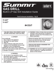
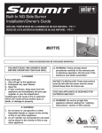
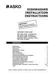
®
SUMMIT
#
42376
BUILT-IN LP SIDE BURNER INSTALLATION/OWNER'S GUIDE
BUILT-IN LP SIDE BURNER INSTALLATION/OWNER'S GUIDE
®
Summit Built-In LP Side Burner
THESE ACCESSORIES MAY BE PURCHASED SEPARATELY.
YOU MUST READ THIS OWNERS GUIDE
BEFORE OPERATING YOUR GAS GRILL
DANGER
If you smell gas:
1. Shut off gas to the appliance.
2. Extinguish any open flames.
3. Open lid.
4. If odor continues, keep away from the
appliance and immediately call your gas
supplier or your fire department.
Leaking gas may cause a fire or explosion
which can cause serious bodily injury or
death, or damage to property.
WARNING
1. Do not store or use gasoline or other
flammable liquids or vapors in the vicinity
of this or any other appliance .
2. An LP cylinder not connected for use shall
not be stored in the vicinity of this or any
other appliance.
WARNING: Follow all leak-check procedures
carefully in this manual prior to barbecue
operation. Do this even if the barbecue was
dealer-assembled.
NOTICE TO INSTALLER: These instructions
must be left with the owner and the owner
should keep them for future use.
THIS GAS APPLIANCE IS DESIGNED FOR
OUTDOOR USE ONLY.
WARNING: Do not try to light this appliance
without reading the “Lighting Instructions”
section of this manual.
42376 US 01/10/06
LP
2
DANGERS & WARNINGS
DANGER
Failure to follow the Dangers, Warnings and Cautions contained in this Owner’s Manual may result in serious bodily
injury or death, or in a fire or an explosion causing damage to property.
WARNINGS
Do not store a spare or disconnected liquid propane cylinder under or near this barbecue.
Improper assembly may be dangerous. Please carefully follow the assembly instructions in this manual.
®
After a period of storage, and/or nonuse, the Weber Built-In side burner should be checked for gas leaks and burner
obstructions before use. See instructions in this manual for correct procedures.
®
Do not operate the Weber Built-In side burner if there is a gas leak present.
Do not use a flame to check for gas leaks.
®
Combustible materials should never be within 24 inches (11 mm) of the top, bottom, back or sides of your Weber
Built-In side burner.
Do not put a barbecue cover or anything flammable on, or in the storage area under the barbecue. Built-In side
burner barbecue should never be used by children. Accessible parts of the barbecue may be very hot. Keep young
children away while it is in use.
®
You should exercise reasonable care when operating your Weber Built-In side burner. It will be hot during cooking
or cleaning and should never be left unattended, or moved while in operation.
Should the burner go out while in operation, turn the gas valve off. Open the lid and wait five minutes before
attempting to relight, using the lighting instructions.
Never lean over open side burner or place hands or fingers on the front edge of the side burner.
Should a grease fire occur, turn off burner and leave lid closed until fire is out.
Do not enlarge valve orifices or burner ports when cleaning the valve or burner.
®
The Weber Built-In side burner should be thoroughly cleaned on a regular basis.
Liquid propane gas is not natural gas. The conversion or attempted use of natural gas in a liquid propane unit or
liquid propane gas in a natural gas unit is dangerous and will void your warranty.
Do not attempt to disconnect any gas fitting while your barbecue is in operation.
Use heat-resistant barbecue mitts or gloves when operating barbecue.
Keep any electrical supply cord and the fuel supply hose away from any heated surfaces.
Combustion byproducts produced when using this product contain chemicals known to the state of California to
cause cancer, birth defects, or other reproductive harm.
Do not use this Built-In side burner unless all parts are in place. The unit must be properly assembled according to
the instructions outlined in the “Assembly Instruction” section of the Owner’s Guide.
LIQUID PROPANE GAS UNITS ONLY:
®
Use the regulator that is supplied with your Weber gas barbecue.
Do not attempt to disconnect the gas regulator or any gas fitting while your barbecue is in operation.
A dented or rusty liquid propane cylinder may be hazardous and should be checked by your liquid propane supplier.
Do not use a liquid propane cylinder with a damaged valve.
Although your liquid propane cylinder may appear to be empty, gas may still be present, and the cylinder should be
transported and stored accordingly.
If you see, smell or hear the hiss of escaping gas from the liquid propane cylinder:
1.
2.
3.
Move away from liquid propane cylinder.
Do not attempt to correct the problem yourself.
Call your fire department.
WARRANTY
WARRANTY
Weber-Stephen Products Co. (Weber) hereby warrants to the ORIGINAL
®
PURCHASER of this Weber gas grill that it will be free of defects in
material and workmanship from the date of purchase as follows:
Stainless Steel Lid,
All Remaining Parts,
10 years
5 years
when assembled and operated in accordance with the printed instructions
accompanying it.
Weber may require reasonable proof of your date of purchase.
THEREFORE, YOU SHOULD RETAIN YOUR SALES SLIP OR INVOICE.
This Limited Warranty shall be limited to the repair or replacement of
parts that prove defective under normal use and service and which on
examination shall indicate, to Weber’s satisfaction, they are defective.
Before returning any parts, contact the Customer service representative in
your region using the contact information sheet provided with your manual.
®
®
If Weber confirms the defect and approves the claim, Weber will elect to
replace such parts without charge. If you are required to return defective
®
parts, transportation charges must be prepaid. Weber will return parts to
the purchaser, freight or postage prepaid.
This Limited Warranty does not cover any failures or operating difficulties
due to accident, abuse, misuse, alteration, misapplication, vandalism,
improper installation or improper maintenance or service, or failure to
perform normal and routine maintenance, including but not limited to
damage caused by insects within the burner tubes, as set out in this owner’s
manual.
Deterioration or damage due to severe weather conditions such as hail,
hurricanes, earthquakes or tornadoes, discoloration due to exposure to
chemicals either directly or in the atmosphere, is not covered by this Limited
Warranty.
There are no other express warrants except as set forth herein and any
applicable implied warranties of merchantability and fitness are limited in
duration to the period of coverage of this express written Limited Warranty.
Some regions do not allow limitation on how long an implied warranty lasts,
so this limitation may not apply to you.
®
Weber is not liable for any special, indirect or consequential damages.
Some regions do not allow the exclusion or limitation of incidental or
consequential damages, so this limitation or exclusion may not apply to you.
®
Weber does not authorize any person or company to assume for it
any other obligation or liability in connection with the sale, installation,
use, removal, return, or replacement of its equipment; and no such
®
representations are binding on Weber .
This Warranty applies only to products sold at retail.
WEBER-STEPHEN PRODUCTS CO.
Customer Service Center
1890 Roselle Road, Suite 308
Schaumburg, IL 60195
USA
www.weber.com®
3
OPERATING
WARNING: Only use this barbecue outdoors in a
well-ventilated area. Do not use in a garage, building,
breezeway or any other enclosed area.
WARNING: Your Summit® Built-In gas barbecue shall
not be used under an unprotected combustible roof or
overhang.
WARNING: Your Summit® Built-In gas barbecue is not
intended to be installed in or on recreational vehicles
and/or boats.
WARNING: Do not use the barbecue within 24 inches
(600 mm) of combustible materials, top, bottom, back
or sides of the grill.
WARNING: The entire cooking box gets hot when in
use. Do not leave unattended.
WARNING: Keep any electrical supply cord and the fuel
supply hose away from any heated surface.
WARNING: Keep the cooking area clear of flammable
vapors and liquids such as gasoline, alcohol, etc., and
combustible materials.
WARNING: Never store an extra (spare) LP cylinder
under or near the Weber® gas barbecue.
WARNING: Keep the ventilation openings of the
cylinder enclosure free and clear of debris.
WARNING: Turn off the gas at the LP gas supply
cylinder when the outdoor cooking gas appliance is not
in use.
WARNING: Never store an outdoor cooking
gas appliance indoors unless the LP cylinder is
disconnected and removed from the outdoor cooking
gas appliance.
WARNING: LP cylinders must be stored outdoors out
of the reach of children and must not be stored in a
building, garage, or any other enclosed area.
STORAGE AND/OR NONUSE
®
• The gas must be turned off at the liquid propane cylinder when the Weber
gas barbecue is not in use.
4
GAS INSTRUCTIONS
LOCATING YOUR BUILT-IN SIDE BURNER
NOTE: If you have questions on what materials are considered
noncombustible, contact you local building supplier or fire department.
BUILT-IN SRUCTURE CUTOUT DIMENSIONS
All dimensions are to finished surfaces.
Any Surface
24 inches min.
for lid clearance
Side
Burner
24 inches
WARNING: The structure, “island” counter tops and
adjacent work areas for the LP Tank Cabinet installation
must be built from noncombustible materials only.
24 inches
CLEARANCE FROM COMBUSTIBLE SURFACES OR
STRUCTURES
WARNING: Clearance from the outside walls of the
sides and back of the LP Tank Cabinet must be a minimum
of 24 inches any surface. Refer to “Typical Gas Supply
Installation” before starting installation.
24 inches Any Surface
Any Surface
When determining a suitable location for your Built-In Side Burner installation,
give attention to concerns such as exposure to wind, proximity to traffic paths,
and keeping any gas supply lines as short as possible. Never locate the Sum®
mit Built-In Side Burner in a garage, breezeway, shed, under an unprotected
overhang, or other enclosed area. Locate the Side Burner and structure so
there is enough room to safely evacuate the area in case of a fire.
Note: For a countertop
treatment: Recommended
3/4 inch overhang. Notch
front edge for frame to
fully slide in.
WARNING: All counter top finished surfaces must be
constructed of a noncombustible material.
A
B
C
Side Burner
Cut out Dimensions Tolerances
+ 1/4" - 1/4"
10 12"
+ 1/4" - 1/4"
3 3/4"
+ 1/4" - 1/4"
16 1/4"
GAS INSTRUCTIONS
BUILT-IN GAS LINE LOCATIONS
GENERAL CONSTRUCTION DETAILS
•
•
®
Summit Built-In side burner unit should be on site before construction
begins.
All dimensions have a tolerance of plus or minus +/- 1/4” inch.
Provide access for a corrugated gas line depending on the location of the
side burner in relation to your main gas supply and regulator position.
Area should be kept clear of sharp, jagged, or extremely abrasive surfaces
to avoid possible damage to gas supply lines. Exercise caution when pulling
gas lines through built-in structure.
5
TEST CONNECTIONS
All connections and joints must be thoroughly tested for leaks in
accordance with local codes and all listed procedures in the latest
edition of ANSI Z223.1/NFPA 54.
DANGER
Do not use an open flame to check for gas leaks. Be
sure there are no sparks or open flames in the area
while you check for gas leaks. This will result in a fire
or explosion which can cause serious bodily injury or
death, and damage to property.
A 3/8 “ inch stainless steel corrugated gas line should be used to connect
the side burner to the regulator accessory coupling.
WARNING: Do not use a rubber gas hose.
3!%STAINLESS
CORRUGATEDGASLINE
4YPICALTANK
CABINETLOCATION
MOUNTING THE SIDE BURNER
Connect the corrugated gas line to the side burner valve located on
the back right hand side of side burner.
Be sure to secure the side burner unit with non corrosive screws
anchored into the finished surface of the “island structure”.
Replace the plastic plug on the front mounting hole to conceal the screw
once side burner is secure.
GAS INSTRUCTIONS
6
TYPICAL BULK PROPANE GAS SUPPLY INSTALLATION
GAS LINE PIPING
We recommend that this installation be done by a LICENSED
professional.
General Specifications for Piping
Note - Contact your local municipality for building codes regulating
outdoor gas grill installations. In absence of Local Codes, you must
conform to the latest edition of the National Fuel Gas Code ANSI Z223.1/
NFPA 54.
•
•
•
•
•
This grill is designed to operate at 10.5 inches of water column
pressure. An LP in line regulator may be necessary for this pressure.
•
CAUTION: If young children are in the area, a
locking valve should be considered.
•
•
•
•
•
Pipe compound should be used which is resistant to the action of
liquid propane gas when gas connections are made.
The gas connections must be firmly attached to rigid, permanent
construction.
•
Refer to the piping chart at the bottom of previous page.
The corrugated gas line from the manifold is 58 inches long. Do not
extend the gas line.
We have provided the means to make an SAE 45° flare connection.
Do not use pipe sealant on this connection.
If the length of line required does not exceed 50 feet, use a 5/8”
O.D. tube. One size larger should be used for lengths greater than
50 feet. Refer to piping chart.
Gas piping may be copper tubing, type K or L; polyethylene plastic
tube, with a minimum wall thickness of .062 inch; or standard weight
(schedule 40) steel or wrought iron pipe.
Copper tubing must be tin-lined if the gas contains more than 0.3
grams of hydrogen sulfide per 100 cubic feet of gas.
Plastic tubing is suitable only for outdoor, underground use.
Gas piping in contact with earth, or any other material which may
corrode the piping, must be protected against corrosion in an
approved manner.
Underground piping must have a minimum of 18” cover.
Note: The information provided in this manual is general for typical
installations. We cannot cover all possible installation ideas. We
recommend, prior to installation, that you contact your municipality
for local building codes and your local fire department for installation
verification.
If you have any questions, contact Customer Service at 1-800-446-1071.
Table
10-1
Maximum Capacity of Pipe in Cubic Feet of Gas per Hour for Gas Pressures of 0.5 psi or Less and a Pressure Drop of 0.3 Inch
Water Column. (Based on a 0.60 Specific Gravity Gas)
Nominal
Iron Pipe
Size
(Inches)
Internal
Diameter
(Inches)
Length of Pipe (Feet)
10
20
30
40
50
60
70
80
90
100
125
150
175
200
1/4
.364
32
22
18
15
14
12
11
11
10
9
8
8
7
6
3/8
.493
72
49
40
34
30
27
25
23
22
21
18
17
15
14
1/2
.622
132
92
73
63
56
50
46
43
40
38
34
31
28
26
3/4
.824
278
190
152
130
115
105
96
90
84
79
72
64
59
55
1
1.049
520
350
285
245
215
195
180
170
160
150
130
120
110
100
1 1/4
1.380
1050
730
590
500
440
400
370
350
320
305
275
250
225
210
1 1/2
1.160
1600
1100
890
760
670
610
560
530
490
460
410
380
350
320
2
2.067
3050
2100
1650
1450
1270
1150
1050
990
930
870
780
710
650
610
2 1/2
2.469
4800
3300
2700
2300
2000
1850
1700
1600
1500
1400
1250
1130
1050
980
3
3.068
8500
5900
4700
4100
3600
3250
3000
2800
2600
2500
2200
2000
1850
1700
4
4.026
17500
12000
9700
8300
7400
6800
6200
5800
5400
5100
4500
4100
3800
3500
©1997 National Fire Protection Association, Inc., and International Approval Services - U.S., Inc. All Rights Reserved.
GAS INSTRUCTIONS
TEST CONNECTIONS
1).
All connections and joints must be thoroughly tested for leaks in accordance
with local codes and all listed procedures in the latest edition of the National
Fuel Gas Code ANSI Z223.1/NFPA 54.
DANGER
Do not use an open flame to check for gas leaks. Be
sure there are no sparks or open flames in the area
while you check for gas leaks. This will result in a fire
or explosion which can cause serious bodily injury or
death, and damage to property.
TYPICAL 20 LP PROPANE GAS SUPPLY INSTALLATION
®
We strongly recommend that you use the Summit Built-In
Tank Cabinet (#21280) for installations using a 20 lb LP cylinder, mounted
remotely in an “island” structure.
®
The Summit Built-In Tank Cabinet is a CSA listed accessory for installing
®
a remote mounted 20 lb LP cylinder, in an “island” structure. Summit BuiltIn Tank Cabinet has a hose and regulator assembly and gas connections,
®
for connecting a remote mounted LP cylinder to the Summit Built-In gas
grill. The hose and regulator is listed as a required part of the CSA listed
®
Summit Built-In gas grill.
®
The Summit Built-In Tank Cabinet also meets the requirements for venting,
tank retention and separation of the LP cylinder from a heat source as
outlined in the ANSI Standard for Outdoor Cooking Gas Appliances, Z21.58/
CSA 1.6 for LP enclosures.
®
The Summit Built-In Tank Cabinet has its own installation guide.
®
If you do not use the Summit Built-In Tank Cabinet, you need to hire
a licensed contractor or licensed plumber and they need to follow the
requirements described in the ANSI Standard for Outdoor Cooking Gas
Appliances, Z21.58/CSA 1.6 for LP enclosures.
The requirements described in the Standard for Outdoor Cooking Gas
Appliances, Z21.58/CSA 1.6. are as follows;
A remote enclosure for an LP gas cylinder shall be ventilated by openings at
both the upper and lower levels of the cylinder. This shall be accomplished
by one of the following:
a).
One side of the remote LP cylinder enclosure shall be completely
open; or
b).
If the remote LP cylinder enclosure is designed to have four sides,
a top and a bottom, ventilation is required for the remote LP cylinder
enclosure;
7
There should be at least two ventilation openings, (a hole or group
of holes, for the purpose of ventilation) in the sidewalls of the island
structure. The openings should be located within 5 inches (127mm) of
the top of the enclosure. The ventilation openings should be equally
sized and spaced at a minimum of 90 degrees, and be unobstructed.
The openings shall have a total free open area of not less than 20
square inches. (This relates to 1 square inch of ventilation area, per
pound of stored fuel capacity).
2). Ventilation openings (a hole or group of holes, for the purpose of
ventilation) should be provided at floor level. The ventilation openings
should have a total free area of not less than 10 square inches. (This
relates to 1/2 square inch of ventilation area, per pound of stored
fuel capacity). There should be at least two ventilation openings
if the ventilation openings at floor level are in the sidewall. The
ventilation openings should be within 5 inches (127mm) of the floor.
The ventilation openings should be of equal size and be spaced at a
minimum of 90 degrees, and should be unobstructed.
3). The minimum size of the ventilation hole (s) should not be less than 1/4
inch.
4). The ventilation openings in the sidewalls should not allow venting into
the empty or “hollow” area of the “island”. If a gas leak should occur
or the LP cylinder should vent in the LP cylinder enclosure, the gas
should not be allowed to vent or migrate into the empty or “hollow” area
of the “island”. Ventilation openings in the sidewalls of the enclosure
should only communicate with the outside of the “island” structure, so
that the gas can dissipate outside of the “island” structure.
c). If the remote LP cylinder enclosure has four sides, a top and a bottom,
and is intended for installation in a built-in “island” enclosure;
1). At least one ventilation opening (a hole or group of holes, for the
purpose of ventilation) needs to be on one side of the enclosure
that communicates with the outside of the “island” structure. If a gas
leak should occur or the LP cylinder should vent in the LP cylinder
enclosure, the gas should not be allowed to vent or migrate into the
empty or “hollow” area of the “island”. Ventilation openings should only
communicate with the outside of the “island” structure, so that the gas
can dissipate outside of the “island” structure. The ventilation opening
should be located within 5 inches (127mm) of the top of the enclosure,
and should have a total free area of 20 square inches. (This relates to
1 square inch of ventilation area, per pound of stored fuel).
2). At least one ventilation opening (a hole or group of holes, for the
purpose of ventilation) needs to be on one side of the enclosure that
communicates with the outside of the “island” structure, at the bottom.
If a gas leak should occur or the LP cylinder should vent in the LP
cylinder enclosure, the gas should not be allowed to vent or migrate
into the empty or “hollow” area of the “island”. Ventilation openings
should only communicate with the outside of the “island” structure,
so that the gas can dissipate outside of the “island” structure. The
ventilation opening should be located within 5 inches (127mm) of the
bottom of the enclosure, and should have a total free area of 10 square
inches. (This relates to 1/4 square inch of ventilation area, per pound
of stored fuel).
GAS INSTRUCTIONS
8
3).
The minimum size of the ventilation hole (s) should not be less than 1/4
inch.
d). The remote LP cylinder enclosure should be constructed with noncombustible materials. The remote LP cylinder enclosure should isolate
the LP cylinder from the burner compartment, so that it provides shielding
from radiation, be a flame barrier and provide protection from foreign
material such as hot drippings.
e). There should be a minimum of 2 inches (50.8mm) between the ground
and the floor of the remote LP cylinder enclosure.
f). The LP cylinder valve should be readily accessible for hand operation.
A door on the remote LP cylinder enclosure to gain access to the LP
cylinder valve is acceptable, provided it is non-locking and can be opened
without the use of tools.
If your licensed contractor or licensed plumber builds an LP cylinder enclosure
following the guidelines in the ANSI Standard for Outdoor Cooking Gas
Appliances,
Z21.58 CSA 1.6, you need to order kit number (#21287), which will contain the
hose and regulator assembly, mounting bracket for the regulator, connection
fittings and LP tank bracket for retaining the LP cylinder that must be used with
®
the Summit Built-In gas grill. The hose and regulator in the kit (#21287) is
®
listed as part of the CSA listed Summit Built-In gas grill.
If you do not follow the DANGER statements exactly, the Warranty on the
®
Summit Built-In gas grill will be voided.
CONNECT GAS SUPPLY
1)
Uncap the flare fitting from the optional side burner connection located
®
inside the Summit Built-In Tank Cabinet (#21280).
®
Note: We strongly recommend that you use the Summit Built-In Tank
Cabinet (#21280) for installations using a 20 lb LP cylinder, mounted
remotely in an “island” structure.
If your, licensed contractor or licensed plumber, builds an LP cylinder
enclosure following the guidelines in the ANSI Standard for Outdoor
Cooking Gas Appliances,
Z21.58 CSA 1.6, you need to order kit number (#21287).
2)
Connect the corrugated gas line to the side burner Connection.
top of
box
90º
fitting
DANGER
Use of any other hose and regulator assembly could be
dangerous, and may not provide adequate gas supply to
®
the Summit Built-In gas grill, and could result in a fire
or an explosion causing serious bodily injury or death,
and damage to property.
DANGER
®
Failure to use the Summit Built-In Tank Cabinet for a
20 lb cylinder or failure to build a LP cylinder enclosure
for a 20 lb cylinder following the requirements for
ventilation, cylinder retention and separation of the LP
cylinder from a heat source, listed in the ANSI Standard
for Outdoor Cooking Gas Appliances, ANSI Z21.58 CSA
1.6, could be dangerous, and could result in a fire or an
explosion causing serious bodily injury or death and
damage to property.
Plug unused hole
with supplied plug.
back of
box
Cap
(Optional
Side Burner)
Connection to
LP Tank
Side View
top of
box
90º
fitting
Plug unused hole
with supplied plug.
back of
box
Connection to
LP Tank
to side burner
Side View
GAS INSTRUCTIONS
TEST CONNECTIONS
All connections and joints must be thoroughly tested for leaks in accordance
with local codes and all listed procedures in the latest edition of AS5601/
AG601.
DANGER
Do not use an open flame to check for gas leaks. Be
sure there are no sparks or open flames in the area
while you check for gas leaks. This will result in a fire
or explosion which can cause serious bodily injury or
death, and damage to property.
FILL LIQUID PROPANE CYLINDER
To fill, take the liquid propane cylinder and filler adapter to an RV center or
look up gas-propane in the phone book for other sources of liquid propane
gas.
WARNING: We recommend that your liquid propane
cylinder be filled at an authorized liquid propane gas
dealer by a qualified attendant, who fills the tank by
weight.
9
CONNECTING THE LIQUID PROPANE CYLINDER
WARNING: Make sure that the LP cylinder valve is
closed. Close by turning valve clockwise.
DANGER
Do not use an open flame to check for gas
leaks. Be sure there are no sparks or open
flames in the area while you check for leaks.
Sparks or flames will result in a fire or
explosion which can cause serious bodily
injury or death, and damage to property.
We utilize various LP tank manufacturers. Some of the tanks have differing
top collar assembles. (The top collar is the metal protective ring around the
valve.) One series of tanks mount with the valve facing front. The other tanks
mount with the valve facing away from the fuel scale. These types of tanks
are illustrated below.
You will need: LP cylinder, a soap and water solution and a rag or brush to
apply it.
1) Turn the LP cylinder so the opening of the valve is either to the front, side
®
or rear of the Weber gas barbecue. Lift and hook the cylinder onto the
fuel gauge.
IMPROPER FILLING IS DANGEROUS.
The liquid propane cylinder must be installed, transported and stored in an
upright position, and should not be dropped or handled roughly.
Never store or transport the liquid propane cylinder where temperatures can
reach 125°F / 51°C (too hot to hold by hand – for example: do not leave the
liquid propane cylinder in a car on a hot day).
For full instructions on safe handling of liquid propane cylinders, see Section
“Operating”.
2)
IMPORTANT LP CYLINDER INFORMATION
Failure to follow these DANGER statements exactly may result in a fire
causing death or serious injury.
DANGER
NEVER store a spare LP cylinder under or near this
barbecue.
NEVER fill the tank beyond 80% full.
WARNING: Only use this grill outdoors in a
well-ventilated area. Do not use in a garage, building,
breezeway or any other enclosed area.
CHECK THAT ALL BURNER VALVES ARE OFF
Valves are shipped in the OFF position, but you should check to be sure that
they are turned OFF. Check by pushing down and turning clockwise. If they
do not turn, they are off. Proceed to the next step. If they do turn,
continue turning them clockwise until they stop, then they are off. Proceed to
the next step.
Loosen the cylinder lock wing nut. Swing the cylinder lock down. Tighten
the wing nut.
10
GAS INSTRUCTIONS
To Connect the hose to the cylinder:
3) Remove the plastic dust cover from the valve.
4) Screw the regulator coupling onto the tank valve, clockwise, or to the
right. Hand-tighten only.
CHECK FOR GAS LEAKS
After a period of nonuse, we recommend that you perform the following
maintenance procedures for your safety.
WARNING: Check the hose before each use of the
grill for nicks, cracking, abrasions or cuts. If the hose
is found to be damaged in any way, do not use the grill.
®
Replace using only Summit authorized replacement
®
hose. Contact the Summit Built-In Customer Service at
1-800-446-1071.
•
•
Note: This connection tightens clockwise and will not allow gas to flow unless
the connection is tight. The connection requires tightening by hand only.
WARNING: Do not use a wrench to tighten the
connection. Using a wrench could damage the
regulator coupling and could cause a leak.
5)
6)
Mix soap and water.
Turn on the cylinder valve.
Inspect the burner for correct flame pattern. Clean if necessary,
following the procedures outlined in the “General Maintenance” section
of this manual.
Check all gas fittings for leaks.
DANGER
Do not use an open flame to check for gas
leaks. Be sure there are no sparks or open
flames in the area while you check for leaks.
Sparks or open flames will result in a fire or
explosion, which can cause serious bodily
injury or death and damage to property.
WARNING: You should check for gas leaks every time
you disconnect and reconnect a gas fitting.
Note - All factory-made connections have been thoroughly checked for gas
leaks. The burners have been flame-tested. As a safety precaution however,
you should recheck all fittings for leaks before using your Weber Gas Barbecue. Shipping and handling may loosen or damage a gas fitting.
WARNING: Perform these leak checks even if your
barbecue was dealer or store assembled.
7)
8)
Check for leaks by wetting the fitting with the soap and water solution
and watching for bubbles. If bubbles form, or if a bubble grows, there is a
leak.
If there is a leak, turn off the gas and tighten the fitting. Turn the gas back
on and recheck with the soap and water solution.
®
If leak does not stop, contact the Summit Built-In Customer Service at
1-800-446-1071. Do not use the barbecue.
When leak checking is complete, turn gas supply OFF at the source and
rinse connections with water.
You will need: a soap and water solution, and a rag or brush to apply it.
Note - Since some leak test solutions, including soap and water, may be
slightly corrosive, all connections should be rinsed with water after checking
for leaks.
Make sure side burner is OFF.
To perform leak checks: open cylinder valve by turning the cylinder valve
hand-wheel counterclockwise.
WARNING: Do not ignite burners when leak checking.
Check for leaks by wetting the connections with the soap and water solution
and watching for bubbles. If bubbles form or if a bubble grows, there is a
leak.
Check:
1) Corregated gas line-to-Accessory “T” Connection
2) Regulator-to-Cylinder connection.
WARNING: If there is a leak at connection (1),
retighten the fitting with a wrench and recheck for
leaks with soap and water solution.
If a leak persists after re-tightening the fitting, turn
OFF the gas. DO NOT OPERATE THE GRILL. Contact
Customer Service 1-800-446-1071.
OPERATING
11
SAFE HANDLING TIPS FOR LIQUID PROPANE GAS CYLINDERS
Check:
3) “T” Connection-to-Hose connections.
4) The hose-to-Regulator connection.
•
WARNING: If there is a leak at connections (2,3, or
4), turn OFF the gas. DO NOT OPERATE THE GRILL.
Contact Customer Service 1-800-446-1071.
When leak checks are complete, turn gas supply OFF at the source and
rinse connections with water.
•
•
•
(1)
Side View
(2)
Liquid Propane (LP) gas is a petroleum product as are gasoline and
natural gas. LP gas is a gas at regular temperatures and pressures. Under
moderate pressure, inside a cylinder, LP gas is a liquid. As the pressure is
released, the liquid readily vaporizes and becomes gas.
LP gas has an odor similar to natural gas. You should be aware of this
odor.
LP gas is heavier than air. Leaking LP gas may collect in low areas and
prevent dispersion.
To fill, take the LP cylinder to an RV center, or look up “gas-propane” in the
phone book for other sources of LP gas.
WARNING: We recommend that your LP cylinder be
filled at an authorized LP gas dealer, by a qualified
attendant, who fills the tank by weight. IMPROPER
FILLING IS DANGEROUS.
WARNING: If you exchange your LP cylinder, make
sure you get a similar tank in return. Your LP cylinder is
equipped with a quick closing coupling or type 1 valve
and an OPD (Overfilling Prevention Device). Other LP
cylinders may not be compatible with your barbecue
connection.
•
Air must be removed from a new LP cylinder before the initial filling. Your
LP dealer is equipped to do this.
• The LP cylinder must be installed, transported and stored in an upright
position. LP cylinders should not be dropped or handled roughly.
• Never store or transport the LP cylinder where temperatures can reach
125° F (51.7° C) (too hot to hold by hand - for example: do not leave the
LP cylinder in a car on a hot day).
Note - A refill will last about 20 hours of cooking time at normal use. The fuel
scale will indicate the propane supply so you can refill before running out. You
do not have to run out before you refill.
• Treat “empty” LP cylinders with the same care as when full. Even when the
LP tank is empty of liquid there still may be gas pressure in the cylinder.
Always close the cylinder valve before disconnecting.
(3)
(4)
Side View
CAUTION: When transporting the LP cylinder make
sure the plastic dust cover is in place over the valve.
This will keep dust and dirt from the threaded portion
of the valve.
•
Do not use a damaged LP cylinder. Dented or rusty LP cylinders or LP
cylinders with a damaged valve may be hazardous and should be replaced
with a new one immediately.
OPERATING
12
LIGHTING THE SIDE BURNER.
LIQUID PROPANE (LP) CYLINDER(S)
•
•
•
The joint where the hose connects to the LP cylinder must be leak tested
each time the LP cylinder is reconnected. For example, test each time the
LP cylinder is refilled.
Be sure the regulator is mounted with the small vent hole pointed
downward so that it will not collect water. This vent should be free of dirt,
grease, bugs etc.
®
The LP cylinder and connections supplied with your Weber gas barbecue
have been designed and tested to meet government, American Gas
Association, and Underwriters Laboratories requirements.
(1)
1)
2)
Open the side burner lid.
Check that the side burner valve is turned OFF. (Push knob in and turn
clockwise to ensure that it in the off position.)
WARNING: The burner control knob must be in the
OFF position before turning on the liquid propane
cylinder valve. If it is not in the OFF position, when
you turn on the LP cylinder valve, the “excess gas
flow control” feature will activate, limiting the flow
of gas from the LP cylinder. If this should occur, turn
OFF the LP tank valve and burner control knobs. Then
start over.
DOT 4BA240
3)
4)
5)
00/02
(2)
Turn the LP tank valve on (turn counter-clockwise).
Push in and turn the side burner control valve to START/HI.
Push igniter button and hold until burner ignites. You will hear the
igniter sparking.
CAUTION: Side burner flame may be difficult to see
on a bright sunny day.
WARNING: If the side burner does not light:
If you have questions about spare LP cylinders contact
Customer Service at 1-800-446-1071.
•
•
•
All LP tank supply systems must include a collar to protect the cylinder
valve.
The LP cylinder must be a 20-lb. size (18 1/4 inches high, 12 1/4 inches in
diameter).
The cylinder should be constructed and marked in accordance with
the Specifications for LP - Gas Cylinders of the U.S. Department of
Transportation (D.O.T.) or the National Standard of Canada,
CAN/CSA-B339, Cylinders, Spheres and Tubes or Transportation of
Dangerous Goods; and Commission, as applicable.
SIDE BURNER LIGHTING INSTRUCTIONS
DANGER
Failure to open the lid while igniting the side
burner, or not waiting 5 minutes to allow the gas
to clear if the side burner does not light, may
result in an explosive flame-up which can cause
serious bodily injury or death.
1) Turn OFF the side burner control valve.
2) Wait 5 minutes to let the gas clear before you try
again or try to light with a match.
TO EXTINGUISH
Push down and turn each burner control knob clockwise to the OFF
position. Turn gas supply OFF at the source.
MAINTENANCE
MANUALLY LIGHTING THE SIDE BURNER
13
®
CROSSOVER IGNITION SYSTEM OPERATIONS
®
DANGER
Failure to open the lid while igniting the side
burner, or not waiting 5 minutes to allow the
gas to clear if the side burner does not light,
may result in an explosive flame-up which can
cause serious bodily injury or death.
If the Crossover ignition system fails to ignite the LEFT burner in a
burner set, light the LEFT burner with a match. If the LEFT burner lights
®
with a match, then check the Crossover ignition system.
•
Check that both ignition wires(1,2) are attached properly.
®
•
Check that the Crossover ignition button is activating.
•
You should hear the igniter sparking.
®
If the Crossover ignition system still fails to light, contact the Customer
Service Representative in your area using the contact information on our
®
web site. Log onto www.weber.com .
REPLACE IGNITER BATTERIES
1)
2)
Open the side burner lid.
Check that the side burner valve is turned OFF. (Push the knob down
and turn clockwise to ensure that it is in the off position.)
WARNING: The burner control knob must be in the
OFF position before turning on the liquid propane
cylinder valve. If it is not in the OFF position, when
you turn on the LP cylinder valve, the “excess gas
flow control” feature will activate, limiting the flow
of gas from the LP cylinder. If this should occur, turn
OFF the LP tank valve and burner control knobs.
Then start over.
3)
4)
5)
6)
Parts required: 1 AA alkaline battery per igniter.
Unscrew igniter button from front of control panel. Remove igniter button and
contact spring. Remove old battery and replace with a new AA
alkaline battery. Positive end (1) of battery faces inward as shown in illustration. Replace spring contact (2) and screw igniter button (3) back onto battery
compartment.
Turn the LP tank valve on (turn counter-clockwise).
Put match in a match holder and strike match.
Push down and turn the side burner control valve to START/HI.
Hold match holder and lit match by right side of side burner.
(2)
(1)
7)
Push igniter button and hold until burner ignites. You will hear the
igniter sparking.
CAUTION: Side burner flame may be difficult to see
on a bright sunny day.
WARNING: If the side burner does not light:
1) Turn OFF the side burner control valve.
2) Wait 5 minutes to let the gas clear before you try
again or try to light with a match.
(3)
SIDE BURNER TROUBLESHOOTING
14
PROBLEM
CHECK
CURE
Side Burner does not light.
Is gas supply off?
Turn supply on.
Flame is low in HIGH position.
Is the fuel hose bent or kinked?
Straighten hose.
Is LP fuel low or empty?
Refill LP cylinder.
The excess flow safety device, which
is part of the barbecue to cylinder
connection, may have activated.
To reset the excess flow safety device turn all burner control
knobs and the cylinder valve OFF. Disconnect the regulator
from the cylinder. Turn burner control knobs to HIGH. Wait at
least 1 minute. Turn burner control knobs OFF. Reconnect the
regulator to the cylinder. Turn cylinder valve on slowly. Refer to
“Lighting Instructions”.
Does burner light with a match?
If match lights burner, check igniter (see below).
Push button ignition does not work.
If problems cannot be corrected by using these methods, please contact the Customer Service Representative in your region using the contact
information sheet provided with your manual.
SIDE BURNER MAINTENANCE
WARNING: All gas controls and supply valves should be
in the OFF position.
1)
2)
Igniter Wire
Burner
(3)
Make sure wire is connected between the igniter and electrode. Spark should
be a white/blue color, not yellow.
Side Burner Grate
Side Burner Cap
Side Burner Ring & Head
Igniter Electrode
Control Knob
Igniter
15
ATTENTION: This product has been safety tested and is only certified for use in a specific country. Refer to
country designation located on outer carton.
These parts may be gas carrying or gas burning components. Please contact Weber-Stephen Products Co., Customer Service Department for
genuine Weber-Stephen Products Co. replacement part(s) information.
WARNING: Do not attempt to make any repair to gas carrying or gas burning components without contacting
Weber-Stephen Products Co., Customer Service Department. Your actions, if you fail to follow this product
Warning, may cause a fire or an explosion resulting in serious personal injury or death and damage to property.
WEBER-STEPHEN PRODUCTS CO.
®
www.weber.com
©2003 The following trademarks are registered in the name of Weber-Stephen Products Co., an Illinois corporation, located at 200 East Daniels Road, Palatine, Illinois 60067 U.S.A.
Australia; Smokey Joe, Weber, Kettle Silhouette , Genesis, Austria; Kettle Silhouette , Smokey Joe, Weber, Benelux; Kettle Silhouette , Smokey Joe, Weber, Compact Grill Configuration, Botswana; Weber, Canada; Smokey Joe, Genesis, China; Kettle Silhouette , Denmark; Kettle Silhouette , Smokey Joe, Weber, Finland; Smokey Joe, France; Kettle Silhouette ,
Smokey Joe, Weber, One-Touch, Germany; Smokey Joe, Weber, One-Touch, Greece; Smokey Joe, Ireland; Kettle Silhouette , Smokey Joe, Italy; Smokey Joe, Weber, Japan; Smokey
Joe, Weber, Korea; Smokey Joe, Weber, New Zealand; Weber, Smokey Joe, Nigeria; Weber, Norway; Smokey Joe, Weber, Portugal; Weber, South Africa: Smokey Joe, Weber, Kettle
Configuration, Spain; Smokey Joe, Weber, Sweden; Kettle Silhouette , Smokey Joe, Switzerland; Kettle Silhouette , Smokey Joe, Weber, United Kingdom; Smokey Joe, Weber, Weber
One-Touch, U.S.A..; Kettle Configuration, Kettle Silhouette , Smokey Joe, Weber, One-Touch, Firespice, Go-Anywhere, U.S.A.;Kettle Configuration, Kettle Silhouette, Genesis, Flavorizer, Crossover, Flamgo, Performer, Rapidfire, Tuck ‘N Carry, Jumbo Joe, Bar-B-Kettle, Master-Touch, Spirit, Grill Out, Summit, Platinum, 1-800-Grill-Out, Ranch, Matchless Flame,
Zimbabwe; Weber, Kettle Configuration, Kettle Silhouette .
®
®
®
®
®
®
®
®
®
®
®