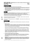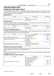
1
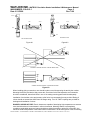
WATLOW IND. WATROD Circulation Heater Installation & Maintenance
I&M NUMBER: 316-42-5-1
Date: 6/11/2008
Manual
Page: 1
Rev: 2.00
________________________________________________________________________________________________________________________________________________________________________________________________________________________
Pre Installation
•
•
Check to make sure that heater received is the same as that ordered.
Watlow heaters are built to comply with UL and CSA dielectric requirements, it may be necessary due to
atmospheric conditions / humidity, to perform a dielectric test prior to startup. (Refer to megohm test
under Installation section)
Safety
Electric heaters are inherently dangerous!! Care should be taken to read and completely understand the
Installation and Maintenance manual before installing and wiring the heater. Any installation and
maintenance performed on the heater shall be done by a qualified electrician, in accordance with the
"National Electric Code" and other electrical codes as they apply. It is the users responsibility to ensure that
the heater being used is properly selected and installed in the application.
!
The Caution Symbol (exclamation point) alerts you to a "CAUTION", a safety or
functional hazard which could affect your equipment or its performance.
The warning symbol (lightning bolt) alerts you to a "WARNING", a safety hazard which
could affect you and the equipment
Installation
Proper heater selection and installation will result in efficient heat transfer, safe operation, and long heater
life.
1. Megohm precheck
During shipping and/or storage, the possibility of moisture absorption by the insulation material within the
element is possible. To ensure proper megohm values a minimum 500 VDC megohm meter (Megger)
should be used to ensure that the megohm reading between the heater terminal and the heater sheath is
more than 10 megohms when the unit is at room temperature.
If several units are interconnected, the megohm of the heater is obtained by taking the reading and
dividing by the number of interconnected elements. This reading should be greater than 10 megohms.
If a low megohm value exists, two alternative methods can be used to remedy the situation. The best
method is to remove all terminal hardware including thermostat if provided, and bake out the heater at no
higher than 250°F (120°C) overnight or until an acceptable reading is reached. The second method is to
energize the unit at low voltage in air until the megohm is at an acceptable reading. Care should be
taken to prevent the heater sheath from exceeding 750°F (398°C) for Incoloy® and steel elements
and 400°F (204°C) for copper elements. Both of these methods should be performed with the heater out
of the tank. The orientation of the heater in relation to the tank should be observed in order to reposition
the heater properly. This is especially important if a high limit thermocouple is provided.
2.
Protection of heater elements from over temperature
The use of temperature controls to regulate heating process and prevent heater over temperature is
highly recommended to ensure safe heater operation. It is the users responsibility to ensure safety of
the installation.
WARNING: Install high temperature control protection in systems where an over temperature
fault condition could present a fire hazard or other hazard. Failure to install temperature control
protection where a potential hazard exists could result in damage to equipment and property,
and injury to personnel.
WATLOW IND.n # 6 INDUSTRIAL LOOP RD. n HANNIBAL MO, 63401n PHONE 573-221-2816 n FAX 573-221-3723
WATLOW IND. WATROD Circulation Heater Installation & Maintenance
I&M NUMBER: 316-42-5-1
Date: 6/11/2008
Manual
Page: 2
Rev: 2.00
________________________________________________________________________________________________________________________________________________________________________________________________________________________
Failure of components in a temperature control loop, such as the sensor, heater control relay or main
temperature control, can result in damage to a product in process, a melt down of a heater, and / or
damaging fire.
To protect against this possibility, over temperature protection must be provided to interrupt or remove
power from the heater circuit. A bulb and capillary thermostat is not recommended for this function
since it may not respond quickly enough to adequately protect the heater. In cases where the
thermostat bulb gets too hot before the system is turned off, the thermostat bulb could rupture.
This could result in the thermostat remaining in the "ON" condition since there is insufficient
fluid to move contacts apart. We recommend the temperature protection have appropriate third party
approval, and be applied in the classification for which it was tested and approved.
In order to help prevent premature failure and a potentially hazardous condition in cases where
consequences of failure may be severe, use an appropriate third party approved liquid level protection
device. The liquid level should be such that the entire heater is fully submerged with enough liquid above
the heater to adequately dissipate heat from itself as under normal operating conditions. Consult your
local authorized sales representative for specific recommendations for your application.
3. Terminal Enclosures
Terminal enclosures should be selected to be compatible with the environment in which the heater will
be located. It is the users responsibility to determine the need for correct rating of the electrical housing.
This should be based on appropriate national and local electrical codes. Failure to use a compatible
enclosure could result in heater damage and personnel danger.
Standard terminal enclosures are designed for general purpose use and are rated NEMA 1. These
enclosures should be applied where there will be no danger of spilled liquids, dampness, dirt, and
gaseous conditions. Enclosures for wet or hazardous locations are also available, but must be installed
at the factory.
Although enclosures are supplied over the terminals, units should be located in an area that will minimize
the chance of being hit by falling or moving objects. The terminals must be protected at all times from
moisture or vapor.
In hazardous locations, (as defined in NFPA 70, NEC, Article 501) explosion resistant housings must be
used.
In order to maintain termination integrity, the terminal enclosure should be kept below 400°F
(204°C).
4. Orientation / Mounting
Furnish adequate space for horizontal or vertical installation. Space should be allowed for immersion
heater removal from tank.
Approved methods for installation of air (gas) and liquid units are shown in Figures # 1 and # 2. Take
careful note of the inlet and outlet locations. Positions other than shown are not recommended.
Figure # 3 shows the preferred position of the circulation heater when pumping liquid from a tank
through the heater. The NPSH (Net Positive Suction Head) is one of the most important factors when
determining the location of the heater.
WATLOW IND.n # 6 INDUSTRIAL LOOP RD. n HANNIBAL MO, 63401n PHONE 573-221-2816 n FAX 573-221-3723
WATLOW IND. WATROD Circulation Heater Installation & Maintenance
I&M NUMBER: 316-42-5-1
Date: 6/11/2008
Manual
Page: 3
Rev: 2.00
________________________________________________________________________________________________________________________________________________________________________________________________________________________
OUTLET
INLET
OUTLET
OUTLET
OUTLET
INLET
INLET
INLET
LIQUID APPLICATION
AIR / GAS APPLICATION
Figure # 1
Figure # 2
NPSH
PUMP
INCORRECT HEATER POSITION - HEATER ABOVE NPSH
NPSH
PUMP
CORRECT HEATER POSITION - HEATER BELOW NPSH
Figure # 3
When installing piping connections, care should be taken to avoid supporting the tank by the nozzles.
Mounting blocks are provided to help prevent this. Provisions for thermal expansion and contraction
should be considered, slotted bolt holes in one of the mating mounting pads would do adequately.
Installation of an isolation valve and pressure relief valve is recommended but not provided. Rating of
valves should not exceed the ANSI class 150 flange rating. Two 1/2" FNPT couplings are provided for
drainage and installation of valves.
DANGER: HAZARD OF FIRE. Electric heaters are capable of developing high temperatures so extreme
care should be taken to locate heaters in safe environments. Mounting heaters in atmospheres
containing combustible gases and vapors should be avoided. According to article 501 of the NEC, the
maximum surface temperature of the heater shall not exceed 80 % of the auto-ignition of the surrounding
WATLOW IND.n # 6 INDUSTRIAL LOOP RD. n HANNIBAL MO, 63401n PHONE 573-221-2816 n FAX 573-221-3723
WATLOW IND. WATROD Circulation Heater Installation & Maintenance
I&M NUMBER: 316-42-5-1
Date: 6/11/2008
Manual
Page: 4
Rev: 2.00
________________________________________________________________________________________________________________________________________________________________________________________________________________________
atmosphere when the heater is continuously energized. Care should also be taken to keep combustible
materials far enough away to be free of the effects of high temperatures.
5. Wiring
WARNING; HAZARD OF ELECTRIC SHOCK. Any installation involving electric heaters must be
grounded to earth to eliminate shock hazard.
Electrical wiring to the heaters must be installed in accordance with the National Electric Code and any
state and local electrical code by qualified personnel.
Consult wiring diagram supplied with the unit for correct feeder or leadwire connections. If wiring
diagram is not supplied, the factory should be consulted for the appropriate wiring diagram. Feeder wire
should be properly selected based on amperage, electrical power rating, ambient temperature, and type
of environment. Feeder wire should also be housed in either rigid or flexible conduit which carries the
same classification as the heater enclosure. It is the users responsibility to properly size and install
feeder wire.
Feeder wire line connections may be made directly to stud terminals or box type compression fittings.
Box type compression fittings will accept a #4 AWG maximum wire while stud terminals will accept a
#10 ring connector(T&B, Amp, etc.). It is essential that these connections be tight. Stud terminals should
be tightened to a maximum torque of 20 in-lbs while the bottom nut is supported. Ground connection
(color coded "green") is supplied inside the housing for ground wire.
Line voltage must be equal to or less than rating stamped on the heater assembly. Some units are
supplied as dual voltage . Example: 240V / 480V, check wiring diagram supplied with the unit to make
sure which scheme was used. In most cases (unless specified by customer) units are wired for the
higher voltage.
Thermostats can be supplied with circulation heaters. Consult the wiring diagram supplied with the
heater for the suggested wiring of thermostats. For safe operation of thermostats, consult Installation and
Maintenance manual for thermostats that is attached.
Thermostats should not be used as an "OFF" device; the use of a disconnect switch or circuit breaker is
recommended. The disconnect switch will allow isolation of the heater when maintenance of the heater
is required.
Start Up
Before energizing the heater the following items should have been checked with the heater power
disconnected:
1. Electrical termination is tight and wiring is per wiring diagram supplied with heater
2. Proper disconnecting means and fusing have been installed
3. The voltage rating of the heater is the same as that being applied
4. Megohm is within acceptable limits
5. Proper temperature controls and safety limiting devices are in place
6. Heater is securely installed in tank header and no leaks are visible
Before energizing heater, correct fluid flow should be maintained over the heater bundle to ensure that
heater elements do not overheat and fail.
After applying power to the heater make sure that the system is being controlled properly before leaving it to
run unattended. Failure to do this could result in overheating resulting in personnel danger and fire.
Thermal cycling may cause the gasket or sealed joints to relax causing a leak. On flange units, tighten bolts
to re-seat gasket. If the leak persists, contact factory for a new gasket. On screw plug units, tighten threaded
WATLOW IND.n # 6 INDUSTRIAL LOOP RD. n HANNIBAL MO, 63401n PHONE 573-221-2816 n FAX 573-221-3723
WATLOW IND. WATROD Circulation Heater Installation & Maintenance
I&M NUMBER: 316-42-5-1
Date: 6/11/2008
Manual
Page: 5
Rev: 2.00
________________________________________________________________________________________________________________________________________________________________________________________________________________________
plug. If leak persists, remove heating unit and add teflon tape or sealing compound to threads and re-install.
Care should be taken to observe the orientation of the flange or plug to its original position.
Troubleshooting
PROBLEM
Cause / Correction
No power available to heater
Check disconnect switch to ensure it is in the "ON" position
and that fuses are not blown. Replace fuses if they are blown
Fuses blowing
Check heater electrical rating. Applied voltage may be wrong
Check fuse rating. Fuses should be at least 25% more than full
load amperage.
Disconnect heater power source. Check the heater resistance
to ground. This should be no less than 1 Megohm. Refer to
Megohm checking.
Not enough power
Check line voltage to ensure it is within specification
Check full line current if voltage is correct. If line current is lower,
the heater may be wired wrong or has open elements
Fluid not heating to desired
temperature
Not enough Kw
Too much heat loss
High limit tripping / alarm
Not enough fluid flow
Too much Kw
Line voltage higher than designed / allowable
Preventative Maintenance
!
CAUTION: HAZARD OF ELECTRIC SHOCK. TURN ALL POWER TO HEATER OFF, USE
APPROPRIATE DISCONNECT LOCKOUTS AND ALLOW SYSTEM/HEATER TO COOL BEFORE
PERFORMING ANY MAINTENANCE
Check line connections to make sure they are tight, free of oxide build-up, and that no dust or dirt build-up is
present. Retighten to 20 in-lbs as necessary.
Check enclosure (inside) for rust, dirt or dust. Remove rust if present, with steel wool (or equal) and
thoroughly blow clean with dry, oil-free air.
If enclosure is moisture resistant, check condition of cover gasket. A replacement can be obtained from the
factory.
Liquid immersed units should be removed from tank and checked periodically for scale build-up. Clean as
required. Scale can cause high sheath temperature and result in inefficiency and shortened life. When the
heater is removed or tightened, take care to orient the heater in the position it was originally
oriented.
Replacement Parts
Reference the Circulation heater part number on the nameplate when ordering replacement parts.
Recommended spare parts would be : an immersion heater, flange gasket, and thermostat (if supplied).
WATLOW IND.n # 6 INDUSTRIAL LOOP RD. n HANNIBAL MO, 63401n PHONE 573-221-2816 n FAX 573-221-3723
WATLOW IND. WATROD Circulation Heater Installation & Maintenance
I&M NUMBER: 316-42-5-1
Date: 6/11/2008
Manual
Page: 6
Rev: 2.00
________________________________________________________________________________________________________________________________________________________________________________________________________________________
Contact your local Watlow distributor for ordering replacement parts. Check the Yellow Pages under
"Electrical Heating Elements" in the largest industrial area nearest you.
Warranty
Watlow warrants its products against defects in material and workmanship for 12 months from the date of
delivery for custom products and 18 months for stock products providing such products are properly applied,
used and maintained. Watlow does not warrant any product against damage from corrosion, contamination,
misapplication, improper specification or operating conditions beyond our control. The terms of this warranty
are the exclusive terms available to any person. No person has authority to bind the Company to
representation or warranty other than this warranty. Watlow is not liable for incidental or consequential
damages resulting from use of the product whether a claim for such damages is based upon warranty,
contract, negligence or other fault. Should any product fail under these warranty conditions it will be repaired
or replaced at no charge. Advanced authorization must be obtained within 30 days of failure.
Return Policy
1.
Call Watlow Industries at 573-221-2816, for a Return Material Authorization (RMA) number before
returning any item for repair or replacement. The following information is needed to process a returned
heater expeditiously:
•
•
•
•
•
•
•
Customer name
•
Customer account number
Contact Name
•
Phone Number
Part number
•
P.O. number
Quantity
Reason for return
Application information
MSDS sheet of material(s) that came in contact with heater, if used.
2. Prior approval and an RMA number is needed when returning any unused product for credit. Make
sure the RMA number is on the outside of the carton, and on all paperwork. Return all material
Freight Prepaid basis.
3. Stock heaters and accessories which have not been used or modified can be returned to the plant
for a 20% restocking charge. Modified stock units can only be returned, if they are not permanently
modified, for a minimum 30% restocking charge.
4. All stock and modified stock must have a date code no later than 2 years from the date of shipment.
WATLOW IND.n # 6 INDUSTRIAL LOOP RD. n HANNIBAL MO, 63401n PHONE 573-221-2816 n FAX 573-221-3723
WATLOW IND. WATROD Circulation Heater Installation & Maintenance
I&M NUMBER: 316-42-5-1
Date: 6/11/2008
Manual
Page: 7
Rev: 2.00
________________________________________________________________________________________________________________________________________________________________________________________________________________________
REVISIONS
LEVEL
1.00
2.00
DESCRIPTION
Created Document
HAN2838
INITIALS
DATE
TBR
06-11-08
WATLOW IND.n # 6 INDUSTRIAL LOOP RD. n HANNIBAL MO, 63401n PHONE 573-221-2816 n FAX 573-221-3723