1
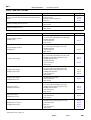
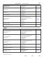
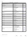
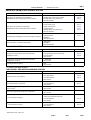
BE–3
BODY ELECTRICAL
–
TROUBLESHOOTING
BE0DD–04
TROUBLESHOOTING
PROBLEM SYMPTOMS TABLE
The table below will be useful for you in troubleshooting these electrical problems. The most likely causes
of the malfunction are shown in the order of their probability. Inspect each part in the order shown, and replace the part when it is found to be faulty.
POWER OUTLET
Symptom
Electric power source cannot be taken out of the power outlet
Suspect Area
See page
1. Battery
2. RR CIG Fuse (Instrument panel J/B)
3. Wire Harness
IGNITION SWITCH:
This system uses the multiplex communication system, so check diagnosis system of the multiplex communication system before you proceed with troubleshooting.
Symptom
Ignition switch is not set to each position.
Suspect Area
See page
1. Ignition switch
2. Power source circuit
BE–33
BE–23
KEY UNLOCK WARNING SWITCH:
This system uses the multiplex communication system, so check diagnosis system of the multiplex communication system before you proceed with troubleshooting.
Symptom
Suspect Area
See page
Key unlock warning system does not operate.
(The buzzer does not sound when the driver’s door is opened with
the ignition OFF and key inserted)
1. Key Unlock Warning Switch
2. Door Courtesy Switch
3. Driver Door ECU
4. Multiplex Communication Circuit
5. Body ECU
6. Wire Harness
BE–33
BE–70
DI–727
DI–838
DI–661
1. Ignition Switch
2. RADIO No.2 Fuse (Instrument Panel J/B)
3. GAUGE Fuse (Instrument Panel J/B)
4. Wire Harness
BE–33
Key unlock warning system does not operate.
(The buzzer sounds when the ignition key is ACC or ON)
HEADLIGHT AND TAILLIGHT SYSTEM:
This system uses the multiplex communication system, so check diagnosis system of the multiplex communication system before you proceed with troubleshooting.
HINT:
To inspect the bulb and light control ECU, replace them with the ones working normally and judge whether
they work normally or not.
(AUTOMATIC LIGHT CONTROL SYSTEM)
Symptom
”Automatic light control system” does not operate.
Suspect Area
See page
1. ECU–IG Fuse (Instrument Panel J/B)
2. DOME Fuse (Engine Room J/B)
3. Automatic Light Control Sensor
4. Light Control Switch
5. Door Courtesy Switch
6. Body ECU
7. Driver Door ECU
8. Wire Harness
BE–38
BE–38
BE–70
DI–661
DI–727
2000 LEXUS LS400 (RM717U)
Author:
Date:
1866
BE–4
BODY ELECTRICAL
–
TROUBLESHOOTING
(AUTO TURN OFF SYSTEM)
Symptom
Suspect Area
See page
Auto turn–off system does not operate when the driver’s door is
opened.
1. Drivers Door Courtesy Switch
2. Driver Door ECU
3. Multiplex Communication Circuit
4. Body ECU
BE–70
DI–727
DI–838
DI–661
Headlight and taillight does not come on.
1. Body ECU
2. Wire Harness
DI–661
Headlight and taillight stays on.
1. Body ECU
2. Wire Harness
DI–661
(USA)
Symptom
Suspect Area
See page
Only one headlight comes on.
(Headlight main)
1. H–LP Fuse (LH–LWR) (Engine Room No.1 R/B)
2. H–LP Fuse (RH–LWR) (Engine Room No.1 R/B)
3. Headlight Main Bulb
4. *Light Control ECU
5. Wire Harness
Only one headlight comes on.
(Headlight sub)
1. H–LP Fuse (LH–UPR) (Engine Room J/B)
2. H–LP Fuse (RH–UPR) (Engine Room J/B)
3. Headlight Sub Bulb
4. *Light Control ECU
5. Wire Harness
”LO–Beam” does not light.
1. H–LP Fuse (LH–LWR) (Engine Room No.1 R/B)
2. H–LP Fuse (RH–LWR) (Engine Room No.1 R/B)
3. Headlight Dimmer Relay (Engine Room J/B)
4. Headlight Dimmer Switch
5. Headlight Main Bulb
6. *Light Control ECU
7. Wire Harness
BE–38
BE–38
”HI–Beam” does not light.
(Headlight main and sub)
1. H–LP Fuse (LH–UPR) (Engine Room J/B)
2. H–LP Fuse (RH–UPR) (Engine Room J/B)
3. Headlight Dimmer Relay (Engine Room J/B)
4. Headlight Dimmer Switch
5. *Light Control ECU
6. Wire Harness
”HI–Beam” does not light.
(Headlight main or sub)
1. Headlight Main or Sub Bulb
2. *Light Control ECU
3. Wire Harness
”Flash” does not light.
(Headlight main and sub)
1. H–LP Fuse (LH–UPR) (Engine Room J/B)
2. H–LP Fuse (RH–UPR) (Engine Room J/B)
3. Headlight Dimmer Relay (Engine Room J/B)
4. Headlight Dimmer Switch
5. *Light Control ECU
6. Wire Harness
”Flash” does not light.
(Headlight main or sub)
1. Headlight Main or Sub Bulb
2. *Light Control ECU
3. Wire Harness
Headlight does not come on.
(Headlight main and sub)
1. Headlight Control Relay (Engine Room J/B)
2. Headlight Dimmer Relay (Engine Room J/B)
3. Light Control Switch
4. Body ECU
5. *Light Control ECU
6. Wire Harness
BE–38
BE–38
BE–38
BE–38
BE–38
BE–38
BE–38
BE–38
BE–38
BE–38
BE–38
BE–38
BE–38
BE–38
DI–661
BE–38
2000 LEXUS LS400 (RM717U)
Author:
Date:
1867
BE–5
BODY ELECTRICAL
–
TROUBLESHOOTING
Headlight does not come on.
(Headlight main or sub)
1. Headlight Main or Sub
2. *Light Control ECU
3. Wire Harness
BE–38
Headlight is flicker.
1. Headlight Main or Sub Bulb
2. Headlight Dimmer Relay (Engine Room J/B)
3. *Light Control ECU
4. Wire Harness
BE–38
BE–38
Headlight is dark.
1. Headlight Main or Sub Bulb
2. *Light control ECU
3. Wire Harness
BE–38
Only one taillight comes on.
1. Taillight Bulb
2. Wire Harness
Taillight does not come on.
(Headlight is normal)
1. TAIL Fuse (Instrument Panel J/B)
2. GAUGE Fuse (Instrument Panel J/B)
3. Taillight Control Relay (Instrument Panel J/B)
4. Light Failure Sensor
5. Light Control Switch
6. Body ECU
7. Wire Harness
Taillight does not come on.
(Headlight does not light)
1. Light Control Switch
2. Wire Harness
BE–38
1. Light Failure Sensor
2. Wire Harness
3. Bulb
BE–76
Rear combination light does not come on.
BE–38
BE–76
BE–38
DI–661
*: HID Type
CANADA:
Symptom
Suspect Area
See page
Only one headlight comes on.
(Headlight main)
1. H–LP Fuse (LH) (Engine Room R/B No.1)
2. H–LP Fuse (RH) (Engine Room R/B No.1)
3. Headlight Main Bulb
4. *Light Control ECU
5. Wire Harness
Only one headlight comes on.
(Headlight sub RH)
1. H–LP Fuse (LH–UPR) (Engine Room J/B)
2. H–LP Fuse (RH–UPR) (Engine Room J/B)
3. Daytime Running Light No.3 Relay
4. Headlight Sub Bulb
5. *Light Control ECU
6. Wire Harness
Only one headlight comes on.
(Headlight sub LH)
1. H–LP Fuse (LH–UPR) (Engine Room J/B)
2. H–LP Fuse (RH–UPR) (Engine Room J/B)
3. Headlight Sub Bulb
4. *Light Control ECU
5. Wire Harness
”LO–Beam” does not light (All).
(Headlight main)
1. Headlight Dimmer Switch
2. *Light Control ECU
3. Wire Harness
”LO–Beam” does not light (One side).
(Headlight main)
1. Headlight Main Bulb
2. *Light Control ECU
3. Wire Harness
”HI–Beam” does not light (All).
(Headlight main)
1. Headlight Dimmer Switch
2. *Light Control ECU
3. Wire Harness
BE–38
BE–38
BE–38
BE–38
BE–38
BE–38
BE–38
BE–38
BE–38
2000 LEXUS LS400 (RM717U)
Author:
Date:
1868
BE–6
BODY ELECTRICAL
–
TROUBLESHOOTING
”HI–Beam” does not light (One side).
(Headlight main)
1. Headlight Main Bulb
2. *Light Control ECU
3. Wire Harness
”Flash” does not light.
(Headlight main)
1. Headlight Dimmer Switch
2. *Light Control ECU
3. Wire Harness
BE–38
BE–38
Headlight does not come on.
(Headlight main)
1. Headlight Control Relay (Engine Room J/B)
2. Daytime Running Light Relay
3. Headlight Dimmer Switch
4. Light Control Switch
5. Body ECU
6. Wire Harness
7. *Light Control ECU
8. Headlight Main Bulb
BE–38
BE–38
BE–38
BE–38
DI–661
Headlight does not come on.
(Headlight sub)
1. Headlight Dimmer Relay (Engine Room J/B)
2. Daytime Running Light Relay
3. Daytime Running Light No.4 Relay
4. *Light Control ECU
5. Wire Harness
BE–38
BE–38
BE–38
BE–38
Headlight does not come on with light control switch in HEAD.
(Headlight main)
1. Light Control Switch
2. Body ECU
3. *Light Control ECU
4. Wire Harness
BE–38
DI–661
BE–38
Headlight does not go out with light control switch in OFF.
(Headlight main
1. Headlight Control Relay (Engine Room J/B)
2. *Light Control ECU
3. Wire Harness
BE–38
BE–38
Headlight is flicker.
1. Headlight Main or sub Bulb
2. Headlight Dimmer Relay (Engine Room J/B)
3. *Light Control ECU
4. Wire Harness
BE–38
BE–38
Headlight is dark.
1. Headlight Main or Sub Bulb
2. *Light control ECU
3. Wire Harness
BE–38
Taillight does not come on with light control switch in TAIL.
(Headlight main)
1. Taillight Control Relay (Instrument Panel J/B)
2. Light Control Switch
3. Wire Harness
BE–38
BE–38
Taillight does not go out with light control switch in OFF.
(Headlight main)
1. Taillight Control Relay (Instrument Panel J/B)
2. Light Control Switch
3. Wire Harness
BE–38
BE–38
Headlight do not come on with engine running and light control
switch in OFF.
(Headlight main)
1. ECU–B Fuse (Engine Room J/B)
2. GAUGE Fuse (Instrument Panel J/B)
3. DRL Fuse (Engine Room R/B No.1)
4. Daytime Running Light Relay
5. Daytime Running Light No.3 and No.4 Relay
6. Body ECU
7. Generator L Terminal
8. Parking Brake Switch
9. Brake Fluid Level Warning Switch
10. *Light Control ECU
11. Wire Harness
BE–38
BE–38
BE–38
BE–38
DI–661
BE–98
BE–98
BE–38
*: HID Type
2000 LEXUS LS400 (RM717U)
Author:
Date:
1869
BE–7
BODY ELECTRICAL
–
TROUBLESHOOTING
HEADLIGHT BEAM LEVEL CONTROL SYSTEM
Symptom
Suspect Area
See page
Beam axis is not controlled. (It is not initialized.)
Headlight Beam Level Control System does not operate.
1. PWR–IG Fuse (Engine Room J/B)
2. Headlight Beam Level Control Actuator
3. Headlight Beam Level Control ECU
4. Wire Harness Side
Beam axis is not controlled. (It is initialized.)
Headlight Beam Level Control System does not operate.
1. Headlight Beam Level Control ECU
2. Power Source Circuit
3. Height Control Sensor
4. Suspension ECU
5. Headlight Beam Level Control ECU
6. Wire Harness Side
BE–52
BE–19
DI–251
IN–32
BE–52
Controlled angle of head light is nnusual. (The angle is controlled.)
1. Height Control Sensor
2. Suspension ECU
3. Headlights
4. Wire Harness Side
DI–251
IN–32
Beam axis position is not stable during driving.
1. ABS System
2. Headlights
3. Wire Harness Side
BE–52
BE–52
FOG LIGHT SYSTEM
Symptom
Suspect Area
Fog light does not light up with light control SW HEAD
(Headlight is normal.)
1. FOG Fuse (Instrument Panel J/B)
2. Fog Light Relay (Instrument Panel J/B)
3. Fog Light Switch
4. Wire Harness
Fog light does not light up with light control SW HEAD
(Headlight does not light).
1. *1 Other Parts
2. Wire Harness
Only one light does not light up.
1. Bulb
2. Wire Harness
See page
BE–56
BE–38
*1: Inspect Headlight System
TURN SIGNAL AND HAZARD WARNING SYSTEM
Symptom
Suspect Area
See page
”Hazard” and ”Turn” do not light up.
1. Hazard Warning Switch
2. Turn Signal Switch
3. Turn Signal Flasher
4. Wire Harness
BE–59
BE–38
BE–59
The flashing frequency is abnormal.
1. Bulb
2. Turn Signal Switch
3. Wire Harness
Hazard warning light does not light up.
(Turn is normal)
1. HAZ Fuse (Engine Room J/B)
2. Wire Harness
Hazard warning light does not light up in one direction.
1. Hazard Warning Switch
2. Wire Harness
BE–59
BE–33
*1 Turn signal does not light up.
1. Ignition Switch
2. TURN Fuse (Instrument Panel J/B)
3. Turn Signal Switch
4. Wire Harness
*2 Turn signal does not light up.
1. TURN Fuse (Instrument Panel J/B)
2. Turn Signal Switch
3. Wire Harness
BE–38
BE–38
BE–38
2000 LEXUS LS400 (RM717U)
Author:
Date:
1870
BE–8
BODY ELECTRICAL
–
TROUBLESHOOTING
Turn signal does not light up in one direction.
1. Turn Signal Switch
2. Wire Harness
Only one bulb does not light up.
1. Bulb
2. Wire Harness
BE–38
*1: Combination Meter, Wiper and Washer do not operate.
*2: Combination Meter, Wiper and Washer are normal.
ILLUMINATION LIGHT SYSTEM
This system uses the multiplex communication system, so check diagnosis system of the multiplex communication system before you proceed with troubleshooting.
Symptom
Suspect Area
See page
Illumination light do not light.
(Taillight is normal)
1. PANEL Fuse (Instrument Panel J/B)
2. Rheostat Light Control
3. Wire Harness
Illumination light do not light.
(Taillight does not light)
1. Taillight Control Relay (Instrument Panel J/B)
2. Taillight System
3. Rheostat Light Control
4. Wire Harness
5. PANEL Fuse (Instrument Panel J/B)
Only one light does not light.
1. Bulb
2. Wire Harness
BE–62
BE–38
BE–38
BE–62
INTERIOR LIGHT SYSTEM
This system uses the multiplex communication system, so check diagnosis system of the multiplex communication system before you proceed with troubleshooting.
Symptom
All the lights do not come ON.
Suspect Area
See page
1. DOME Fuse (Engine Room J/B)
2. DOME Fuse (Engine Room J/B)
3. Body ECU
DI–661
The light does not come ON when the driver’s door is opened.
1. Driver’s Door Courtesy Switch
2. Driver Door ECU
3. Multiplex Communication Circuit
4. Body ECU
5. Wire Harness
BE–70
DI–727
DI–838
DI–661
The light does not come ON when the passenger’s door is
opened.
1. Passenger’s Door Courtesy Switch
2. Front Passenger Door ECU
3. Multiplex Communication Circuit
4. Body ECU
5. Wire Harness
BE–70
DI–760
DI–838
DI–661
The light does not come on when the rear–right door is opened.
1. Rear–Right Door Courtesy Switch
2. Body ECU
3. Wire Harness
BE–70
DI–661
The light does not come on when the rear–left door is opened.
1. Rear–Left Door Courtesy Switch
2. Body ECU
3. Wire Harness
BE–70
DI–661
Only one of the bulbs comes ON.
1. Bulb
The illumination does not fade out when all the doors are closed.
1. Courtesy Switch
2. Driver Door ECU
3. Front Passenger Door ECU
4. Multiplex Communication Circuit
5. Body ECU
6. Wire Harness
BE–70
DI–727
DI–760
DI–838
DI–661
2000 LEXUS LS400 (RM717U)
Author:
Date:
1871
BE–9
BODY ELECTRICAL
–
TROUBLESHOOTING
The illumination does not fade out immediately when the ignition
switch is turned to ACC or ON within 15 seconds after all the
doors are closed.
1. Ignition Switch
2. RADIO NO.2 Fuse (Instrument Panel J/B)
3. GAUGE Fuse (Instrument Panel J/B)
4. Body ECU
5. Wire Harness
BE–33
The illumination does not fade out immediately when all the doors
are locked within 15 seconds after they are closed.
1. Door Unlock Detection Switch
2. Driver Door ECU
3. Front Passenger Door ECU
4. Multiplex Communication Circuit
5. Body ECU
6. Wire Harness
Interior light does not light up.
(in front personal light)
1. Bulb
2. Front Personal Light
3. Wire Harness
BE–70
Front personal light does not light up.
1. Bulb
2. Front Personal Light
3. Wire Harness
BE–70
Rear personal light does not light up.
1. Bulb
2. Rear Personal Light
3. Wire Harness
BE–70
Vanity light does not light up.
1. Bulb
2. Vanity Light
3. Wire Harness
BE–70
Luggage compartment light does not light up.
1. Bulb
2. Luggage Compartment Door Courtesy Switch
3. Wire Harness
BE–70
Courtesy light does not light up.
1. Bulb
2. Door Courtesy Switch
3. Wire Harness
BE–70
DI–661
BE–139
DI–727
DI–760
DI–838
DI–661
STOP LIGHT SYSTEM
Symptom
Suspect Area
Stop light does not light up.
1. STOP Fuse (Instrument Panel J/B)
2. Stop Light Switch
3. Light Failure Sensor
4. Wire Harness
Stop light always lights up.
1. Stop Light Switch
2. Wire Harness
Only one light always lights up.
1. Wire Harness
Only one light does not light up.
1. Bulb
2. Wire Harness
See page
BE–76
BE–76
BE–76
HEADLIGHT CLEANER SYSTEM
Symptom
Suspect Area
See page
”Headlight Cleaner System” does not operate
(Using light control switch)
1. Light control switch
2. Wire Harness
BE–38
”Headlight Cleaner System” does not operate
(When operating ”Running Light System”)
1. Daytime Running Light Relay (Main)
2. Wire Harness
BE–38
2000 LEXUS LS400 (RM717U)
Author:
Date:
1872
BE–10
BODY ELECTRICAL
–
TROUBLESHOOTING
”Headlight Cleaner System” does not operate
(All)
1. AM1 H–Fuse
2. WIPER Fuse
3. Ignition Switch
4. Headlight Cleaner Switch
5. Headlight Cleaner Relay
6. Headlight Cleaner Motor
7. Headlight Cleaner Nozzle and Hose
8. Wire Harness
Washer fluid does not spray
1. Headlight Cleaner Nozzle and Hose
BE–33
BE–79
BE–79
BE–79
WIPER AND WASHER SYSTEM
This system uses the multiplex communication system, so check diagnosis system of the multiplex communication system before you proceed with troubleshooting.
Symptom
Suspect Area
See page
Wiper and washers do not operate.
1. WIPER Fuse (Instrument Panel J/B)
2. Wiper Switch
3. Wiper Motor
4. Body ECU
5. Wire Harness
Wipers do not operate in LO, HI or MIST.
1. Wiper Switch
2. Wiper Motor
3. Wire Harness
BE–82
BE–82
Wipers do not operate in INT.
1. Wiper Switch
2. Wiper Motor
3. Body ECU
4. Wire Harness
BE–82
BE–82
DI–661
Washer motor does not operate.
1. Washer Switch
2. Washer Motor
3. Wire Harness
BE–82
BE–82
Wipers do not operate when washer switch in ON.
1. Washer Motor
2. Body ECU
3. Wire Harness
BE–82
DI–661
Washer fluid does not operate.
1. Washer Hose and Nozzle
When wiper switch is at HI position, the wiper blade is in
contact with the body.
When the wiper switch is OFF, the wiper blade does not
retract or the retract position wrong.
1. Wiper Motor *
2. Wire harness *
3. Body ECU
BE–82
BE–82
DI–661
BE–82
DI–661
*: Inspect wiper arm and blade set position.
COMBINATION METER
Symptom
SRS warning light does not light up.
Hi–beam indicator light does not light up.
Turn indicator light does not light up.
Suspect Area
See page
1. MPX–B Fuse
2. Bulb
3. Meter Circuit Plate
4. Wire Harness
5. Airbag Sensor Assembly
BE–86
DI–574
1. Bulb
2. Meter Circuit Plate
3. Wire Harness
4. Headlight System
BE–86
BE–36
1. Bulb
2. Meter Circuit Plate
3. Wire Harness
4. Turn Signal and Hazard Warning System
BE–86
BE–58
2000 LEXUS LS400 (RM717U)
Author:
Date:
1873
BE–11
BODY ELECTRICAL
ABS warning light does not light up.
TRAC warning light does not light up.
AIRSUS warning light does not light up.
–
TROUBLESHOOTING
1. GAUGE Fuse
2. Bulb
3. Meter Circuit Plate
4. Wire Harness
5. ABS, TRAC and VSC ECU
BE–86
DI–305
1. GAUGE Fuse
2. Bulb
3. Meter Circuit Plate
4. Wire Harness
5. ABS, TRAC and VSC ECU
BE–86
DI–364
1. Bulb
2. Meter Circuit Plate
3. Wire Harness
4. Suspension ECU
BE–86
IN–32
Malfunction indicator light does not light up.
1. Bulb
2. Meter Circuit Plate
3. Wire Harness
4. ECM
Fuel level warning light does not light up.
1. Bulb
2. Fuel level warning switch
3. Meter Circuit Plate
4. Wire Harness
BE–86
BE–98
BE–86
ELECTRIC TENSION REDUCER SYSTEM
Symptom
Suspect Area
Tension Reducer does not operate.
(Driver’s and Passenger’s)
1. PWR–IG Fuse (Instrument Panel J/B)
2. Wire Harness
Tension Reducer does not operate.
(Only one side)
1. Buckle Switch
2. Tension Reducer Solenoid
3. Wire Harness
See page
BE–113
BE–113
DEFOGGER SYSTEM
Symptom
Suspect Area
All defogger systems do not operate.
1. HTR Fuse (Instrument Panel J/B)
2. DEF H–Fuse (Engine Room J/B)
3. Defogger Switch
4. Defogger Relay (Engine Room J/B)
5. Wire Harness
Rear window defogger does not operate.
1. Defogger Wire
2. Wire Harness
Mirror defogger does not operate.
1. MIR–HTR Fuse (Engine Room J/B)
2. Mirror Defogger
3. Wire Harness
See page
BE–116
BE–116
BE–116
BE–116
POWER WINDOW CONTROL SYSTEM
This system uses the multiplex communication system, so check diagnosis system of the multiplex communication system before you proceed with troubleshooting.
Symptom
Suspect Area
See page
All the power windows do not operate.
(Power Door Lock System is normal.)
1. Power Window Master Switch
2. Wire Harness
BE–126
Only the driver’s window does not operate.
1. Power Window Master Switch
2. Power WIndow Switch
3. Power Window Motor
4. Wire Harness
BE–126
BE–126
BE–126
”Window lock function” does not operate.
1. Power Window Master Switch
BE–126
2000 LEXUS LS400 (RM717U)
Author:
Date:
1874
BE–12
BODY ELECTRICAL
–
TROUBLESHOOTING
Window does not operate with power window master switch.
(Manual or Automatic operation can be performed.)
TROUBLESHOOTING NO.1
BE–120
Remove control of all windows (Except driver’s) does not functions with master switch.
(Window operate normally with each of master switch.)
TROUBLESHOOTING NO.2
BE–120
The Key related power window operations does not operate with
driver side door key cylinder.
(Master switch operation is normal.)
TROUBLESHOOTING NO.3
BE–120
Power window does not operate with multi–function transmitter.
(Windows operate normally with master switch.)
TROUBLESHOOTING NO.4
BE–120
Window moves down without being ordered during the up operation.
TROUBLESHOOTING NO.5
BE–120
POWER DOOR LOCK CONTROL SYSTEM
This system uses the multiplex communication system, so check diagnosis system of the multiplex communication system before you proceed with troubleshooting.
Symptom
Suspect Area
See page
All the doors cannot be locked or unlocked.
1. Door Lock Control Switch
2. Driver Door ECU
3. Front Passenger Door ECU
4. Multiplex Communication Circuit
5. Body ECU
6. Wire Harness
BE–139
DI–727
DI–760
DI–838
DI–661
Only driver’s side door lock control does not operate.
1. Driver Door ECU
2. Driver’s Door Lock Motor
3. Wire Harness
DI–727
BE–139
Other doors than the driver’s side door do not operate.
1. Driver Door ECU
2. Multiplex Communication Circuit
3. Body ECU
4. Wire Harness
5. Door Lock Motor
DI–727
DI–838
DI–661
BE–139
Door key related function does not operate.
1. Door Key Lock and Unlock Switch
2. Wire Harness
BE–139
1. Key Unlock Warning Switch
2. Wire Harness
3. Body ECU
BE–33
Key confinement prevention function does not operate.
Luggage compartment door opener function does not operate.
DI–661
1. Luggage Compartment Door Opener Switch
2. Luggage Compartment Door Key Lock and
Unlock Switch
3. Luggage Compartment Door Opener Motor
4. Wire Harness
5. Body ECU
BE–139
BE–139
BE–139
DI–661
2000 LEXUS LS400 (RM717U)
Author:
Date:
1875
BE–13
BODY ELECTRICAL
–
TROUBLESHOOTING
THEFT DETERRENT SYSTEM
This system uses the multiplex communication system, so check diagnosis system of the multiplex communication system before you proceed with troubleshooting.
Symptom
Suspect Area
See page
1. Indicator Light
2. Key Unlock Warning Switch
3. Door Unlock Detection Switch
4. Engine Hood Courtesy Switch
5. Luggage Room Door Courtesy Switch
6. Wire Harness
7. Body ECU
8. Driver Door ECU
9. Multiplex Communication Circuit
10. Transmitter
BE–151
BE–33
BE–139
BE–151
BE–70
The system cannot be canceled when the ignition switch is turned
to ACC with key.
1. Key Unlock Warning Switch
2. Ignition Switch
3. Body ECU
4. RADIO NO.2 Fuse (Instrument panel J/B)
5. Wire Harness
BE–33
BE–33
DI–661
The system cannot be canceled when the luggage compartment
door is unlocked with key.
1. Luggage Room Door Courtesy Switch
2. Body ECU
3. Wire Harness
BE–70
DI–661
The system does not operate when the engine hood is opened.
1. Engine Hood Courtesy Switch
2. Body ECU
3. Wire Harness
BE–151
DI–661
The system does not operate when the door is opened or unlocked without using a key or transmitter.
1. Door Courtesy Switch
2. Driver Door ECU
3. Front Passenger Door ECU
4. Body ECU
5. Multiplex Communication Circuit
6. Door Unlock Detection Switch
7. Wire Harness
8. Transmitter
BE–70
DI–727
DI–760
DI–661
DI–838
BE–139
The system does not operate when the ignition switch is turned to
ACC without using a key or transmitter.
1. Ignition Switch
2. Key Unlock Warning Switch
3. Body ECU
4. Wire Harness
5. Transmitter
BE–33
BE–33
DI–661
Some of the does not operate.
(Headlight does not light up)
1. Headlight System
2. Wire Harness
3. Body ECU
BE–36
Some of the system does not operate.
(Taillight does not light up)
1. Taillight System
2. Wire Harness
3. Body ECU
Some of the system does not operate.
(Theft deterrent horn or horn does not sound)
1. Theft Deterrent Horn
2. Horn
3. Horn Relay
4. HORN Fuse (Engine Room J/B)
5. Wire Harness
6. Body ECU
The system cannot be set.
DI–661
DI–727
DI–838
DI–661
BE–36
DI–661
BE–151
BE–257
BE–257
DI–661
2000 LEXUS LS400 (RM717U)
Author:
Date:
1876
BE–14
BODY ELECTRICAL
–
TROUBLESHOOTING
BE–139
DI–661
While the warning is given, the system cannot be canceled by
unlocking the door with key or transmitter.
1. Door Key Lock and Unlock Switch
2. Body ECU
3. Wire Harness
4. Driver Door ECU
5. Front Passenger Door ECU
6. Multiplex Communication Circuit
7. Transmitter
BE–33
BE–33
While the warning is given, the system cannot be canceled by
turning the ignition switch to ON with key.
1. Ignition Switch
2. Key Unlock Warning Switch
3. RADIO NO.2 Fuse (Instrument Panel J/B)
4. GAUGE Fuse (Instrument Panel J/B)
5. Body ECU
6. Wire Harness
The system operates for more then 60 seconds.
DI–727
DI–760
DI–838
DI–661
1. Body ECU
BE–33
WIRELESS DOOR LOCK CONTROL SYSTEM
This system uses the multiplex communication system, so check diagnosis system of the multiplex communication system before you proceed with troubleshooting.
Whole wireless door lock control system does not operate.
Problem occurs only at a specific locality→ Precheck type I (See page BE–154)
Problem occurs everywhere→ Precheck type II (See page BE–154)
Some functions of wireless door lock control system do not operate.
HINT:
Troubleshooting of the wireless door lock control system is based on the premise that the door lock
control system is operating normally. Accordingly, before troubleshooting the wireless door lock control
system, first make certain that the door lock control system is operating normally.
If the trouble still reappears even though there are no abnormalities in any of the other circuits, then
check and replace the Wireless Door Lock Control Receiver as the last step.
Symptom
Suspect Area
See page
All functions of wireless door lock control system do not operate.
1. Wireless Door Lock Control Receiver
2. Wire Harness
BE–161
Wireless door lock operates, but the buzzer does not sound.
1. Wireless Door Lock Buzzer
2. Wireless Door Lock Control Receiver
3. Wire Harness
BE–161
BE–161
POWER SEAT CONTROL SYSTEM
Symptom
Suspect Area
See page
Power seat does not operate.
(Door lock does not operate.)
1. Wire Harness
2. Power Seat Switch (D)
3. Power Seat Switch (P)
BE–172
BE–172
Power seat does not operate.
(Door lock is normal.)
1. Wire Harness
2. Power Seat Switch (D)
3. Power Seat Switch (P)
BE–172
BE–172
Driver’s seat does not operate.
1. Power Seat Switch (D)
2. Wire Harness
BE–172
Passenger’s seat does not operate.
1. Power Seat Switch (P)
2. Wire Harness
BE–172
”Slide operation” does not operate.
1. Power Seat Switch (D)
2. Power Seat Switch (P)
3. Wire Harness
4. Slide Motor (D, P)
BE–172
BE–172
BE–172
2000 LEXUS LS400 (RM717U)
Author:
Date:
1877
BE–15
BODY ELECTRICAL
”Front Vertical Operation” does not operate.
”Rear Vertical Operation” does not operate.
”Reclining Operation” does not operate.
”Lumbar Support Operation” does not operate.
–
TROUBLESHOOTING
1. Power Seat Switch (D)
2. Power Seat Switch (P)
3. Wire Harness
4. Front Vertical Motor (D, P)
BE–172
BE–172
1. Power Seat Switch (D)
2. Wire Harness
3. Rear Vertical Motor (D, P)
BE–172
1. Power Seat Switch (D)
2. Power Seat Switch (P)
4. Wire Harness
4. Reclining Motor (D, P)
BE–172
BE–172
1. Power Seat Switch (D, P)
2. Wire Harness
3. Lumbar Support Motor (D, P)
BE–172
BE–172
BE–172
BE–172
BE–172
(D): Driver’s Seat
(P): Passenger’s Seat
w/ Memory System:
POWER MIRROR CONTROL SYSTEM
This system uses the multiplex communication system, so check diagnosis system of the multiplex communication system before you proceed with troubleshooting.
Symptom
Suspect Area
See page
Both right and left mirror does not operate.
1. RADIO NO.2 Fuse (Instrument Panel J/B)
2. Mirror Switch
3. Tilt & Telescopic ECU
4. Multiplex Communication Circuit
5. Wire Harness
Only one side of interior does not operate.
1. Driver Door ECU (Left Side Mirror)
2. Front Passenger Door ECU (Right Side Mirror)
3. Mirror Motor
4. Wire Harness
DI–727
DI–760
BE–183
BE–183
The mirror does not return to the memorized position.
1. Driving Position Memory
(Position is not set)
2. Driving Position Switch
3. Driver Door ECU
4. Multiplex Communication Circuit
5. Wire Harness
1. Driving Position Memory
(Position is not set)
2. Wire Harness
DI–727
The memorized position is moved.
BE–183
DI–408
DI–838
BE–183
DI–727
DI–838
w/o Memory System:
POWER MIRROR CONTROL SYSTEM
This system uses the multiplex communication system, so check diagnosis system of the multiplex communication system before you proceed with troubleshooting.
Symptom
Suspect Area
See page
Mirror does not operate.
1. RADIO NO.2 Fuse (Instrument Panel J/B)
2. Mirror Switch
3. Mirror Motor
4. Wire Harness
Mirror operates abnormally.
1. Mirror Switch
2. Mirror Motor
3. Wire Harness
DI–727
DI–727
DI–727
DI–727
2000 LEXUS LS400 (RM717U)
Author:
Date:
1878
BE–16
BODY ELECTRICAL
–
TROUBLESHOOTING
POWER SHOULDER BELT ANCHORAGE SYSTEM
This system uses the multiplex communication system, so check diagnosis system of the multiplex communication system before you proceed with troubleshooting.
Symptom
Suspect Area
See page
Driver’s belt anchor can not be operated manually.
1. Shoulder Belt Adjust Switch (Driver’s)
2. Driver Door ECU
3. Multiplex Communication Circuit
4. Tilt and Telescopic ECU
5. Height Adjustable Anchor Motor
6. Wire Harness
BE–188
DI–727
DI–838
DI–408
BE–188
The anchor does not return to the memorized position.
1. Driving Position Memory and Return Switch
2. Driver Door ECU
3. Multiplex Communication Circuit
4. Tilt and Telescopic ECU
5. Wire Harness
BE–188
DI–727
DI–838
DI–408
The memorized position is moved.
1. Height Adjustable Anchor Sensor
BE–188
Passenger’s belt anchor can not be operated manually.
1. Shoulder Belt Adjust Switch (Passenger’s)
2. Shoulder Belt Anchor Relay
3. Wire Harness
4. Height Adjustable Anchor Motor
BE–188
BE–188
BE–188
ELECTRO CHROMIC MIRROR SYSTEM
Symptom
Suspect Area
See page
Electro Chromic Inner Mirror does not operate.
1. ECU–IG Fuse (Instrument Panel J/B)
2. Elector Chromic Inner Mirror
3. Wire Harness
BE–195
Electro Chromic Outer Mirror does not operate.
1. ECU–IG Fuse (Instrument Panel J/B)
2. Electro Chromic Outer Mirror
3. Elector Chromic Inner Mirror
4. Wire Harness
BE–195
BE–195
SEAT HEATER SYSTEM
Symptom
Seat heaters do not operate.
(Driver’s and Passenger’s)
Suspect Area
See page
1. FR S/HTR Fuse (Engine Room J/B)
2. Engine Main Relay (Engine Room J/B)
3. Seat Heater Switch
4. Wire Harness
5. Seat Heater
BE–198
BE–198
BE–198
Driver’s seat heater does not operate.
1. Seat Heater Switch
2. Wire Harness
BE–198
Passenger’s seat heater does not operate.
1. Seat Heater Switch
2. Wire Harness
BE–198
Seat heater temperature is too hot.
1. Seat Heater
BE–198
FUEL LID OPENER SYSTEM
Symptom
Fuel lid opener system does not operate.
Suspect Area
See page
1. FUEL OPN Fuse (Instrument Panel J/B)
2. Fuel Lid Opener Switch
3. Fuel Lid Opener Solenoid
4. Wire Harness
BE–202
BE–202
2000 LEXUS LS400 (RM717U)
Author:
Date:
1879
BE–17
BODY ELECTRICAL
–
TROUBLESHOOTING
GARAGE DOOR OPENER SYSTEM
Symptom
Suspect Area
See page
The equipment of which code has been registered does not operate.
1. Garage Door Opener
2. Wire Harness
3. *
BE–242
LED does not light up. (Even though either switch is pressed.)
1. Garage Door Opener
2. Wire Harness
BE–242
LED does not light up. (Only one switch is pressed.)
1. Garage Door Opener
BE–242
* As the GARAGE DOOR OPENER on the vehicle side seems to be normal, check the OPENER on the
equipment side, of which code has been registered.
HORN SYSTEM
Symptom
Suspect Area
See page
Horn system does not operate.
1. HORN Fuse (Engine Room J/B)
2. Horn Relay (Engine Room J/B)
3. Horn Switch
4. Horn
5. Wire Harness
Horns blow all the time.
1. Horn Relay (Engine Room J/B)
2. Horn Switch
3. Wire Harness
BE–257
BE–257
One horn operates but other horn does not operate.
1. Horn
2. Wire Harness
BE–257
Horns operate abnormally.
1. Horn Relay (Engine Room J/B)
2. Horn
3. Wire Harness
BE–257
BE–257
BE–257
BE–257
BE–257
2000 LEXUS LS400 (RM717U)
Author:
Date:
1880