1
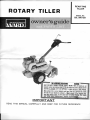
ROTARY TILLER
REARTINE
TILLER
ilnlu0uulllc,Pnftfl||r|0tw
orlly
sptctRmW
tvt0tltlr
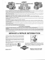
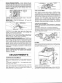
Tifrffibeads
are
nor
pr'perlv
seated,
arrpnssure
ovbr
34pgican
ciuie
ttre
ilil hilertffi ih;
assembly
with
lq_a\pbdeforielullicient
toartae
iiri,iiiolTiiii'i'ijii.iiii.
,beads
Make
certain
rimrscorrect
diarireter
and
type.G.n
rim,lubricat0,,rim,
ilvgiecotaI$iildiil;hp
:l9"t9:8"*1,'"ll'^,^{t,ttt'$eno_fl
beads.
notstand
ovTrffitltffi tatrng-ffiiffi
.Do
: manufacturer's
inflation
recommendetis["-.^:::,
-. __
IMP OR TA N T
READTHIS MANUALCAREFULLY
AND KEEPFOR FUTUREREFERENCE
GONTENTS
Generol Introduction
SofetyTips
InitiolServicing
Controlsond Operotion
StortingYourRotoryTiiler
Adiustments
Seruicingond Mointenqnce
Storoge
TillerPorts
TillerPortsList
Chqin Cose Ports
Choin Cose PortsList
Howto Order Replocementports
3
3
4
4
5
6
I
11
12&14
r 3 &1 5
16
17
20
IMpoRTANT!Recordthe unit model number ond its seriol
number on the bock poge of this monuol for
fulurereterencewhen orderingrepoir portsor identificotionif
unit is lostor stolen.
The monufocturerreseryesthe right lo mqke chonges on
ond to odd improvementsupon its productsol
ony time withoutnotice or obtigttion. The monufqLturerqiso resewes
lhe rightto discontinuemonufoclure of ony product ot itsdiscretionot ony iime
Nolice to customers in lhe Slofe of Colifornio _
The.engine on this unit is trtoT equipped with o
spork orrestingmuffler
WARNING
USE OR OPERATIONOF THIS ENGINE Oil ANY
lqnEsT GOVERED,BBUSH COVEREDOR GRASS
COVEREDLAIIID WITHOUT A STATE APPROVED
SPARK ABRESTERIN EFFECTIVEWORKIITIG
OR.
DER COiISTITUTESA VIOLATIOil OF THE LAW OF
THE STATEOF CALIFOBITIIA.
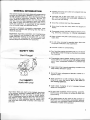
GENERAL INTRODUCTION
ThisOwneis Guide hos been especiolly prepored lo
provide the informotion needed to op'eiote your
tii
ler with greoler sotisfoction.Reod this'Owne/i Guide
ond the engine inslrucfionscorefully. Be sure you
know whot the controls ore for ond how they o[ergte: Ilte core your tiiler requiresis smoil, but'imior_
tont. Keep it cteon ond weit tubricofed. Witn prcjber
core ond operotion,os exploined in this monuof,
you will obtoin long ond efficientservice.
This.tiller,
is .shipped completely ossembled.Afler
reootng this monuol ond servicingtiller the tiller is
reody to operote.
Informolionregording operolion ond mointenonce
of the.engine is nol included in this monuol. A sep_
orole instructionmonuol is included with your liller
ond should be consultedfor oll informoiioncon_
cerning engine odjustmenlsond operolion.
O Inspectwork oreo ond cleor ony objects thot ore
not eorth or mulch.
o lmproper use of the rotory tiller con resull in in_
jury. Give complete ond undivided ottention
fo
the work you ore doing.
O Knowlhe conlrolsond how they operote.
o K.noyhow to stop the rotory tiller ond engine in_
stontly.
o Disengogepower ond stop engine before cleon_
ing, removing obstocles,or mlking odjuslment.
a Keep childrenond petso sofedislonceowoy from
rotory tiller.
o Do.not ollow onyone to operote rotory tiller with_
out proper instructionond supervision.
O Exercisecoution to ovoid folling.
SAFETYTIPS
Don'tForget
o
.?on'tsio.rtthe gngine ond tines until you ore reocty
lo slorttilling.Stopthe engine wheneveryou leov6
the mochine.
O Disengoge clutch before slorting engine. Keep
honds, feet ond clothing owoy from power_driven
porfs. Weor odequoie footweor to prevent foof
InJury.
O Keep rotorytiller in good operoting conditionond
keep sofety devices in ploce.
Do not till neor undergroundelectric cobles or ir_
rigotion hoses.
thot SAFETY
stortswith you!
Store gosoline in o sofe contoiner. Storethe con_
toiner in o cool, dry ploce. Not in the houseor
near heatingappliances.
Open doors if engine is run in goroge. Exhoust
gosesore dongerous.
Yo.urrotory tiller wos built to the highest slondords
in the industry.Howeve_r,
a rotary tilleir is only as safe
as the operaror. As with ony ty-pe of powei equip_
ment,coretessnessor error on th6 pon dr the opeiotbr
con re.sulfin injury. pleose reoci ond follo* these
Insrructionsgn sofe operotion ond be cerloin ony_
one using this rotory tiller is fomilior with fhese sim_
ple rules:
Fill gos tonk outdoors.Avoid spillinq oosoline.
Don'tfill lonk white engine is runningdr inite you
ore smoking.
The replocement of ony porf on fhis product by
ofherthon the monufocture/southorizddreploce_
ment p.orl moy odversely offect the performonce,
durobility or sofety of this producl.
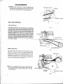
IN I T I A L S E R V I C I NG
1. Before storling the engine, refer fo the engine insfructions.Be cerloin lhe the engine cronkcose
is filled with the proper type oil ond thot oll engine serviceinstructions
hove been followedcompletely.
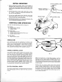
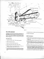
CLUTCHCONTROLLEVER
THROTTLE
CONTROL&
ENGINE
STOP
LEVER
2. Fillfuel tonk wilh o cleon, fresh,leod-free or leoded "regulor'' grode of outomotive gosoline. Do
not mix oil with gosoline.
All nuls ond bolts should be checked ond tightened during lhe firsttwo (2) hoursof use. periodic
checks should be mode thereofler.
HANDLECONTROLLEV
E N GIN EC H OK E
DEPTH
CONTROLLEVER
4. Thetiresore normolly over-inflotedfor shipping.The
recommended lire pressureis 20 lbs.
CONTBOLSAND OPERATION
Thislillerhos the followingconlrols:(Figure1)
ON ENGINE
A. EngineRewindStorter
B. EngineChoke
ON HANDLE
BAR
A. Clutch ControlLever
B. ThrotlleControlond EngineSlop Lever
C. Hondle ControlLever
ON TINESHIELD
A. Depth ControlLever
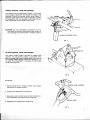
HANDLE BAR
tl
The hondle bor hqs two operoting locotions (see
Figure2).In the fillinglocotion,lhe tinesore immediotely in frontof the operotor.In lhe tronsportlocotion,
the engine is immediotely in front of fhe operofor.
Use lhe hondle control lever lo unlock the hondle,
then positionthe hondle in the desired locotion.
I
HANDLE CONTROL LEVER
j
i
The hondle control lever conlrols the hondle swing
locotionond fhe hondle height.To swingthe hqndle
bor, pull bock on the lever. Swing lo either righl or
lett to lhe desired posilion,then releqse the conlrol
lever ond swing bock ond forthslighilyunfillhe h<.rndle lofchengoges.Toodjuslhondleheighl,pull bock
on control lever withoulswinginghondle. Move hondle to desired heighl. Releoselever ond move hondle up ond down slightlyunlil hondle locks in lhe
desired height position.NOTE:When pulling bock
on the hondle conlrol lever,the clutch conirol lever
is outomoticolly moved to the neutrolposition.
CLUTCH GONTROL LEVER
Theclutch controllever is o single leverthot engoges
ond disengoges drive to both the tines ond lhe
wheels.
FIG,2
Whenthe handlebar is in the tilling location,pushing
forwsrd on lhe control lever engoges the drive fo
bolh the finesond the wheelsot o tillingspeed. CAUTION:Beforepushinglever forword,be cerloin depih
controlsettingis correcffor soilconditions.(SeeDepih
Confrol Lever)
Pulling bock on clulch control lever from forword
drive lo neutroldisengogesthe drive to the tinesond
wheels.Furtherpulling bock on lhe lever engoges
lhe reversedrive to the wheels qnd the tiller moves
bockwords ot fronsportspeed. (Tinesdo not rotote
in reverse.)When releosed,the confrol lever will relurn to neutrolposition.
Whenthe handlebar is in tnansportlocation,fhe clufch
control lever will only operofe by pulling the lever
bock. Thisengoges the drive to the wheels ond the
tiller moves forword of tronsporl speed. When releosed, fhe control lever refurnsto neulrol.
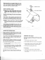
DEPTHCONTROLLEVER
GAUTION:Do nor adiust rilling depth wfth rhe tines
rotatang.Place clutch control leyer in the neutral
position before makhrgadiustments of depth control.
SHAULOWEST
SETTING
The depth conirol lever is the "key" to eosy tilling operotion. Theexoct settingof control will vory wilh soil
condilions.
When storling o tilling operotion, stort with the depth
confrol lever in lhe shollowesf setting (Figure 3). As
you become ocquointed with the soil, keep roising
the control lever so thof deeper tilling con be done.
CAUTfON:ff depth control lever is roised loo high, iV
the lines will propel the tiller fonruordpushing the lV
drive wheelsolong the ground of on uncontrolled
speed.
When sfortingto till unworked soil or sod, sfort in the
shqllowestsettingof fhe depth confrol lever ond roise
lhe depth control one notch ol o time unlil you orrive ol o sofistocforylocolion of the lever so thot the
deepest tilling con be done without hoving unconfrolled fonvord speed.
FIG.3
OPEBATING SUGGESTIONS
Whenyou slortfo till in the gorden,rememberto toke
it eosy. Do nol lry to loke too deep o cul in o poss
through sod or hord ground, or soil thot hos nol been
tilled for severol monfhsor yeors.
Do nol leon on the hondle bors becouse fhis tokes
weight off the front wheels, reduces troction, ond
couses the tines to ottempl to propel the filler insteod of justdigging.
There ore severol schools of thought os to the best
method to till. lt is suggestedyou lry the voriousmethods ond select the one you ore most comfortoble
with lo get lhe resulfsyou desire.
A. On eoch succeeding poss, overlop one-holf of
the previousposs.
B. On the second poss, leove o 1/2 width untilled
ond till lhis width on lhe third poss.Repeoton ihe
fourth poss, leoving o 1/2 width untilled ond on
the fiflhposs,tillthe untilledstrip.
C. UseA or B ond repeoi ot 90 degrees.
Rememberthe key to eosy tilling is the depth control setting.Do nottry lo toke loo deep o cut in horder
soils.
STARTING THE TILLER
Now thot you hove locoted the controlsond undersfond lheir operotion ond function,il is time to stort
your tiller.
1. Ploce clutch confrol lever in neulrol.
2. Pushthrottle control lever oheod to fosl position.
3. Adjustengine choke lo proper posilion.(Referto
engine slortingproceduresin engine seclion.)
4. Slortengine by pulling slorlercord.
To Stop Engine
1. Ploce clutch controllever in neutrolposition.
2. Pull fhrottlecontrol ond engine slop lever to the
stop posilion.
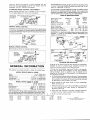
ADJUSTMENTS
CAUTION:Never ofiempt to moke-odjustments
on
fhe lillerwhile the engine is running.Alwoysstop
lhe engine ond disconneclthe wirelrom tn6 spoit
plug before ottemplingto moke odjustments.
ROTATE
CLAMP CAP SCRE\
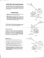
BELT ADJUSTMENTS
TINE DBIVE BELT
The tine drive belt, which is the outer be[, is odjusted by
cop screws (Figuie4) onct roto_
l9_9s9ningthe ctomp qnd
ang me enflre cose
tine ossembly. R6lote cose
fonrord to stocken belt ond bock to fidnten belt, With
the clutch control lever in the forword drlve position,the
disfonce between the inside of fhe betf shoutd be
$Pproximotely 3/4 inch os shown in Figure5. Tighten
the clo.mp bolts securety ofter od j ustmeit. etoce jepm
control in shollowestsettingond itortensine. Withcbn_
trol lever in neutrol position,tines shoult not rofote.lf
flnes rotote,reodjustto increqse bellslock untiltinesdo
notdrive in neutrol.
FIG.4
E N GIN EP U LLE Y
c
TINEDRIVEBELT
3t4
TINEDRIVEPULLEY
WHEELDRIVEBELT
FIG.5
The wheel drive belt, which is the inner beli, is od_
justed by. moving the right hond idter (Figure6). With
the clutch confrol lever in the neutrcjl[ositioh, tfre
troclion belt should hove opproximoiely 1/4 inch
between the upper idler ond the belf (Figure6). The
qdiustmentidler shouldbe positioneO-to
oOtqihthis
1/4 inch. Moving idler up will increosecteoronce
ond down will decreose cleoronce.
NOTE:The odjustmentidler hos four locotions ond
is nol sloi mounted.The mochine screw must be
removed from the mounting frorire when moking
this odjustmenl.
UPPER
I DLER
A D JU S TME NID
T LE R
\
MA C H IN E
SCREW
WHEEL
DRIVE PULLEY
\
FIG.6
HANDLECONTROLLEVERADJUSTMENT
The hondle control odjustmenl(Figure7) hos been
set for proper operotion ond should not need to be
odiusfed.Shouldthe hondle control lever (Figure7)
become loose ofter mony hoursof operolion,tighlen
the odjustmenlnul only enough lo eliminoteony excess movementin the hondle confrol lever.
NUT
ADJUSTMENT
CAUTION:Do nol overtighlen odjuslmenf nut. This
moy resultin foilureof hondle bor lotch systemlo
fully engoge ond hold hondle in desired position.
CLUTCHCONTROLLEVERADJUSTMENT
The clutch control lever is pre-set for neutrol shitt
position.An odjustmenfmeons is provided, however, lo center the clulch control lever in lhe slot on
the hondle shroudshould it become necessorydue
to weor. This odiustmenl is locoted ot fhe hondle
pivol point (Figure8)
TOADJUST:
1. Ploce hondle bor in litling locotion ond odjusl
hondle bor to lowesfposifion.
CLUTCHLEVERCONTROL
2. Loosenthe odiustmentnut (Figure8).
3. Move lhe clutch control lever on the hondle bor
unfil cenfered in lhe neutroloreo (Figure9).
4. Retightenfhe odjustmenlnut (Figure8).
NEUTRAL
AREA
SERVIGINGAND MAINTENANGE
Thebesf ossuronceyou hove of geiling the mosl de_
pendoble service from your tiller is to keep the unit
cleon, free of rust,ond well lubricoted. Check bolts
often lo be sure they ore kept tight. Whenthe tiller is
not being used,it shouldbe storedin o dry ploce out
of lhe weother.
LUBRICATION
1. Engine:Referlo engine operoting instructions
ond
requirementsfor oll engine lubricotion.
2. GhainGases:Both the wheel drive ond the tine
drive coses ore omply filled wifh lubricont ond
shouldnot require odditionol lubricotion.lf o leok
d.evelops,odd teod bose (Ep)SAE140heovy duty
9it (fo!. 4890) os required'to bring to profer oit
level. Check oit tevet every 25 houis.
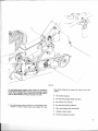
OIL LEVEL& FILLPLUG
FrG.
t0
Thefollowingprocedureshouldbe followedto check
lubricont level of coses. When checking coses, do
not droin excesslubricontout of the cos6s.
WHEELDRIVECASE
To check the oil level of the wheel drive cose, ptoce
the depth control lever down fo lhe shollowesf selling.(Figure 3). Remove the inspection plug on lhe
right side of the wheet drive cose (Figuretb;. Cose
hos sutficient oil if oil is up to bottorn of insfecfion
plug hole. lt moy be more convenienl lo rernove lhe
righl wheel when checking lhis level.
OIL LEVET
FIG.11A
TIilE DRIVECASE
To check the lubricotion level of lhe tine drive cose:
1. Setdepth confrol ot the deepest setting(Figure3).
2. Ploce liller on o level surfoce so lhot lhe tinesond
the wheels ore seiling on lhe ground,Fig.11B.
3. Wipe dirl owoy from oil level plug ond removeplug,
Fig.11A.
Oil should be up to the Obttomof hote. 4. lt oil isn'tup fo bottom of hote,wipe dirt owoy fromoil
fill plug ond remove, Fig. 118.Fiil stowty witn teoO
bose (EP)SAE140heovy duty oil untitproper tevetis
19gche-!. Reptoce oit levet ptug ond dit tiil prr.rg.
Wipe off excessoii.
FIG.lIB
4(l ) ' .
.q...-<-
___=/
4ffi'
Y
a-\
I
\ ',
l*_./
lilll,
t
Fte.12
To odd lubricont to eilher choin cose it is necessory
to tip liller on its lefi side lo expose tevel ptugs of eocn
cose. Add sufficient teod bose (Ep)SAEtaO neovy
duty oil (Port4890) to bring to propdr oit tevet.
fore oiling ottempt lo cleon off oreo lo be lubricoled.
A. The4 idler pulleys.
B. Thehondle plunger shoflond disc.
C. The conirol rod swivels.
3. The following poinls should be lubricoted with
engine oit every eight hours (see Figure12).Be-
D. The hondle roloting surfoce.
E. Com ond detenl boll ond shoft.
F. Hondle control lever.
G. Tinedrive bellcronk pivot.
\
/'/ |
I
.z -.1I
/1
wHEEL
DRtvE
cAsEpuLLEy )..
'/
/
/\
-\
TlNi DRTVEBELT
/
R E TA IN IN G
R IN G
TINEDRIVECASEPULLEY
ptN
BELT
GUTDE
tl8:g!\|rNGR|N-G/
\_-
\r
TINEDRIVE
,,.,}
'O'.'*
BELIGUIDE
\,,
ARM L|NK
-__--.---IDLER
COTTERPIN
F re . 1 3
BEIT REPLACEMENT
Thebells on thistiller.werespecificollydesigned
ond
enginee.redto provide long, trouble_freeservice.
lf
belt replocement is requlred,orOe,ine port
number
shown in the ports list section of thii rn6nuot,
ro
sure you hove o belt thot will provide lhe liie Oe
ond
servicereguired.
l
I
il
TINEDRIVEBELT
1. Ploce the clutch lever in the neulrol position.
2. Removethe bell guord.
3. Removethe bett guide (Figuret3).
4. Slip the belt off ihe tine drive cose puiley.
5. Removebelt from the engine pulley ond
slip out
befween engine puiley oio ioieior'r.
6. To reploce belt, reverseobove procedure.
Be sure
belt.ison top of tine drive idler prf fey oncl lhe
bell
g-uide pin neor the tine drive iosqiu-iley
fflguie
13).
10
7. Reodjust belt os ouflined under belt odjustments.
8. Replqce belt guord.
WHEELORIVEBELT
1. Removethe tine drive belt per instructionsobove.
2. R_emovethe retoining ring in the idler orm shoft
(Figuret3).
3. Removethe belt from lhe wheel drive cose puiley.
4. Removewheel drive pulley by removing reloining
ring ond stiding puildy orindf. (CAUTI6N:
Do no-t
toose woodruff key in drive pulley shoff.)
{Figure
r3).
5. Removecotter pin from idler orm link (Figurei3).
6. Slide idler qrm ossembliesout unlil lhe spocer con
be slid out between the idler ond idler orm. Re.
move belt. To reploce bett reverse oOove piocedure. Be sure bett is turned inside out (wide iide
on puileys) before instoiling in puileys
ffigurat3|
7. Reodjustbelt os ouflined under bell odjuslments.
STOBAGE
For short lerm storoge,cleon the filler off
ond store
In o dry ploce.
3 Runengine untilil stops.
1
lf tiller is not lo be used for on extended period
of
time, service tiller completely onOJi"re it' in -dry
o
ploce.
1
I,
1 Feler to the engine instructions
for engine storoge
inslructions.
i
2. Droingosolinefrom fuel tonk.
4. Cover exposed metol surfoceswith o t hin
coot
of engineoil.
Lub.ricoteper insfructions
under ,,servicingond
Moinlenonce".
Beforeusingthe tillerogoin, check oll lubricotion
go.ints,fill fuel lonk, on-d follow other insiructions
in the owneis guide.
11
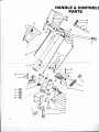
HANDLE& CONTROL
PARTS
q
FI
c
AL-q
o.,-@
^"-?t"
12
,.
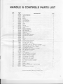
HANDLE & CONTROLSPARTSLIST
RE F .
LET.
A
B
C
D
E
F
G
H
I
J
K
L
M
N
o
P
R
S
T
U
V
W
X
z
AD
AE
AF
AG
AH
AI
AJ
AK
AL
AM
AN
AO
AP
AQ
AR
AS
AT
AU
AV
AW
AX
AY
M
BA
PART
N O.
200469
200470
1'183
200612
2 0 0 11 0
200066
2OO473
200460
200420
200074
33580
2OO075
200323
200768
2 O O1 7 9
200177
200195
200196
200242
200055
200324
200462
33595
2 OOO4 5
2679
200034
D E S C R IP TION
T u n n e l A ssembl y
Handle Assembly
G ri p ..
Slide .
S p ri n g
C o n tro l R od ..
Pivot Assembly . . .
P a w l A s sembl y.. .. .
Pin .. .
Lever.
G ri p . .
Shroud
L i n k As s embl y ....
Lever.
P l u n g o rA ssembl y
R e ta i n e rA ssembl y
C a m As sembl y.....
Be l l c ra n kA ssembl y
Clevis Pin
Spring - Detent
Control Handle Assembly
Control Rod Assembly.. . . .
B a l l ..
Pi n ...
Spacer
Grip . .
Lock Washer- 3/16 Ptated
Cap.Screw - Hex Hd. - 9/16-18 x 11/cPlated
-7 O Q2 2 M a c h i n eS crew - Oval H d. - P hi l . 5/16-18x 1 P tated
Cap Screw Hex Hd. t/a-16x 1 Plated
-70233
.70649
Lock Washer3/ePlated
.70087
Cap Screw - Hex Hd. th-20 x1/z Plaled
.70588
Nut - Flex Jam s/c-16Plated .
Lock Washer th Plated
-70643
2O112O Lock .
18744
Thrust Washer
.70631
Nut - Cone Lock s/e-1
6 Plated .
'70703
Washer - Med. Flal 3/sPlated
.70715 Cotter Pin
1/16 x lz Plated
.70646
Lock Washer 5/16 Plated
.70683 Washer SAE Flat th
Plated
'70721
Cotter Pin t/ax 3/aPlated
' 7 0 4 4 3 C a rri a g eB ol t 5/16-18x 1 P l ated
' 7 0 6 2 9 N u t - C o n e Lock 5/16-18P l ated
16066
Bushing
32861
Clamp
24993
Spacer - Clamp
MachineScrew Rd. Hd. - Va-2O
-70397
x 7aPlated
2OO243 Spacer
Pin, Cotter3/32xs/a Plated .
-70740
-70672
.71072
QTY.
I
I
z
1
1
1
1
1
1
1
1
'1
1
1
1
1
1
1
-l
1
1
1
1
1
1
1
1
1
2
2
1
1
z
2
1
2
2
1
1
1
I
1
1
2
I
1
1
2
.C o mmo n hardw are.
May be purchasedl ocal l y.
13
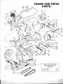
FRAMEAND DRIUE
PARTS
€[--cl
.B P
,BQ
,K
./fl-
a:,t
-;^A
9@/---,"u
BN
BO
J
BG
BF
GJ
'--
AZ
H
'/cL
,fu'"'o
-6
,i^
'@ft{
%c=s
t7"30,--
6tt
cc
==Eg
:?g
rr€
;tr^ffieiSi:
s_;
#tury
-AO
AP
l
s
'l:a-
t-ca
"
-BZ,6\}-V
22tgffiD
6a-6
P artN o.13938 .
P artN o.13255.
M____-_
N
14
CANS OFTOUCH-UPSPRAY
PAINTARE AVAILABLEBY
ORDERING:
. . . . . . G r ay
.. . . . . . Red
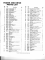
FRAMEAND DRIVE
PARTS LIST
Ref.
Let.
A
B
c
D
E
F
G
H
I
J
K
L
M
N
o
P
o
R
S
T
U
V
W
x
z
AA
AB
AC
AD
AE
AF
AG
AH
l-
AI
AJ
AK
AL
AM
AN
AO
AP
AQ
AR
AS
AT
AU
AV
AW
AX
AY
Part
No.
Description
OtV-
208139 FrameAssembly- R.H.
1
2O814O FrameAssembly- L.H.
1
2O O O 71C o u n te rWe i g h....
t
... 30
2O O A 78C o u n te rWe i g h....
t
8
200165 DepthControlAssembly
1
208810 S k i d As s e mb l y .....
1
j
2OO184 Support Assembly
24897 Handle
z
2O O 197 S p ri n g
. . ......
1
'l
200063 EnginePulley .
2OOO28 Camshaft Pulley .
1
208'142 PulleyAssembly- Tines
1
200555 Traction Drive Belt
1
200554 Tine Drive Belt . . .
1
33632 ldler PulleyAssembly
4
200166 Ti n e D ri v e l d l e rAs s e mb l............
y
1
200164 TractionDrive ldlerAssembly
1
2OO2O7 Pulley Assembly - Traction
1
2O O 422 Sp a c e r-l d l e r.
.... ....
1
200064 Be[Guide
200049 Spacer
20009 Swivel
2OO111 ControlRod . .
200428 Spring - Traction Drive . .
200056 Spring - Tine Drive
2OO421 Bellcrank .. .
200455 Link.. . ... ..
200456 ControtRoo
... : :. :. :.. :. :.. :..... :.
14273 FivotBushing
2762
200613
208175
200194
Washer
z
ChainCase Assembly- Wheel Drive . . 1
Chain Case Assembly- Tine Drive . . . . 1
LU E ..
.... ....
z
Engine- 5 HPB&SModet130292,
Type0803-01
200059 BeltGuard
2OO1'12TineShield
200459 Hinge .
200030 Rod ..
200168 GuardAssembly. . .
208189 TineAssembly
- R.tt.
208192 TineAssembly
- L.H.
240425 Tine- R.H.
200426 Tine- L.H.
1056 FeltSeal
11246 FeltSeal
9545 Washer
200552 Tire& WheelAssembly,
Consists
Of
18945 Tire'13
X 5.00{.
18940 Wheel.
3823 VaiveCap
10631 ValveStem
200553 Tire& WheelAssembly,
Consists
Of
18945 Tire13X 5.00-6
18940 Wheel.
3823 ValveCap
10631 ValveStem
"71079 Machine
Screw,Stotted
FlatHd.s/16-18
x2Ptated":.....
5/16-18Plated.
-70592 Nut,Square
-7O149 CapScrew,Hexi-ld.5/16-18x i"
Plated
Ref.
Let.
M
BA
BB
BC
BD
tsE
BF
BG
BI
BJ
BK
BL
BM
Btl
BO
BP
BQ
BR
BS
BT
BU
BW
BX
EY
BZ
CB
4
I
1
4
t
4
4
4
z
2
.)
'!
I
1
1
I
1
1
I
I
I
1
I
I
CC
CD
CE
CF
CG
CH
cl
CJ
CK
CL
CM
CN
CO
CP
CQ
CR
CS
CT
CU
CV
CW
CX
CY
Part
No.
Description
oty.
.......
-70629 N ut,C oneLock5/16-18Plat ed
I
-70177 Cap Screw,Hex Hd.,5/16-18x
2t/tPlated
3
'70882 Cap Screw,Hex Hd., 9r 16 x 3 Plated . . z
' 70649 W asher,S pri ngLock,7e Plat ed
.......
6
Plated
-70553 Nut, Hex sr'a-16
6
'70137 Cap Screw,Hex Hd. 5/16-18x 5/e
Plated .
I
'70646 Washer,SpringLock 5/16 Plated . . . . . 19
. . . . . . . . . 10
-70549 N ut,H ex5/16 P l ated
........
2
-70603 N ut,S el fLock5/16-18P l a t ed.
1
-71073 B ol t,C arri age5/16-18x2t.h. . . . . . . . .
-70165 Cap Screw,Hex Hd. 5/16-18x ls/a
Plated .
1
"7OO87 Cap Screw,Hex. Hd. 1/t-2Qx1/zPlated. 4
4
-70643 Washer, Spring Lockth Plated .
'70985 Key, Square3/ 16 x 11/z
1
'70497 Set Screw5/'t6-18 x % SocketHd. Cup
PointH.T.
2
"70488 SetScrew th-20x % SocketHd. Cup
PointH.T.
2
.70808 Key,
WoodrultVaxs/a
2
3917 Snap Ring
3
200318 Snap Ring
1
11412 W asher
. . . . . . . 4- 7
3
-70687 Washer, Flat - SAE s/8Plated
-71071 MachineScrew,SlottedPan Hd. Ta-16x
17nPlated
1
'7U4A Cap Screw,Hex Hd. 5/16-18x3/a
Plated .
I
'l
-70699 Washer Med. Flat th Plated
"7A721 Pin, Cotterlaxs/aPlated
4
-7O74O Pin,Cotter3/32x5/ePlated .
2
'70388 MachineScrewSlottedRoundHd.No.
10-24x 1" Plated
2
.70540 Nut, Hex
No. 10-24Plated.
2
-70672 Washer,Ext. Lock No. 10 Plated . . . . . . 2
17002 Washer
2
16
-70232 C apS cr€w ,H exH d.% -16x1". . . . . . . .
'7A648 Washer,SprinELock7e
19
17
-70552 Nut. Hex 3/e-16.
"70301 Cap Screw,Hex Hd. 3/e-24
x 1TaH.T. . . . 2
-70162 Cap Screw,Hex Hd. 5/16-18x 1th . . . . 4
" 70441 B ol t,C arri age5/16-18x
/rPlat ed . . . . . 4
"70133 Cap Screw,Hex Hd. 5/16-18x1/z
Plated .
2
-7O168 Cap Screw,Hex Hd. 5/16-18x 13/a
plated .
2
"7'1090 Cap Screw,Hex Hd. 5/16-18x2rh . . . . 1
'70812 Key,Woodrutl3/16x3/q...
1
2AU41 RetainingRing. .
I
208193 Washer - Back Up
2
9627 FeltSeal
2
24764 Pyramidal Lock Washer
"70554 Nut, Hex YB-24 .
2
1
35886 O-Ring
35887 Cup .
I
'l
37141 OillevelPlug .
37'128 Nylon Wosher
1
18083 Oi l S eol
2
2
*Commonhardware.
May be purchasedlocally.
tc
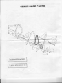
GHAINCASEPABTS
Io reploce oll choin cose seols
ond dosketsorder PortNo.89428.
To reploce entile choin cose less
lines drder Pod No. 89429'
16
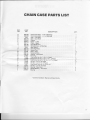
GHAIN GASEPARTSLIST
REF.
LET.
A
B
c
{.**t.r*'
D
E
F
G
H
I
J
K
L
M
N
o
P
o
B
S
T
U
V
W
X
Y
z
PART
N O.
D E S C R IP TION
208162 ChainCase Ass'y.- R.H.w/Bearings. . . .
208163 ChainCase Ass'y.- L.H.w/Bearings
1054
Seal - Tine Shaft. .
208176 Seal - InputShaft .
208052
Gasket
208051 Chain - Lcwer .
208177
Chain - Upper .
2 0 8 1 8 6 In p u tSh a ftA ss' y.
...
208178 SprocketAss'y.w/Bearings
.....
4O2O
ldler Sleeve
208181 Tine ShaftAss'y.. . .
2O81U
SpacerCup
39108
Shim - Gear. .
208141 RetainingRing ..
208185 Washer-lnputShaft
27489
Pipe Plug
CapScrewHexHd. th-Z}x7aPlated
-703M
-70088+,'"*@ap6ercw{rfsre"Hdr%[email protected],T--&Plated
.
*70134
Cap ScrewHex Hd. 5/16-18x thH.T. & ptated.
Hex Nut, Lockt/q-2oPlated .
-70628
"70629
Hex Nut, Lock 5/ 16- 18 Plated .
"70877
Cap Screw,Hex Hd. %-16x 21hH|1.
'70631
Hex Nut, LockTa-16Plated.
208174
Bearing - Input Shaft
208173
Needle Bearing - Tine Shaft
209007 Bearing
*Common
QTY.
1
1
2
1-2
2
2
1
I
'l
:.....;;.:
+2
?
12
3
1
1
2
2
2
hardware. May be purchasedlocally.
l7
ri{/Hff6"
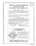
OPERATING
AND MAINTENANCE
INSTRUCTIONS
MODELSERIES
100200to 100299
130200to 131299
IN THE INTERESTOF SAFETY
DO NOT RUN ENGTNEAT EXCESSIVESPEEDS.Operatingan engine at excessivespeedsincreasesthe hazard of personalinjury.
DO NOT TAM PERW I TH PARTSW HI CH M AY I N C R E A S ET H E G O V E R N E DS P E E D .
For rotary lawnmowersafety,A.N.S.l.StandardSafetySpecificationsfor Power Lawn Mowersspecifya maximum blade tip speed of
19,000feet per minute (96.5meters per second),primarilyto reduce the hazardfrom thrown obiects.
Rotary lawnmowermanufacturersselectthe governedtop speed of the engine basedon the length and design of the cutter bladeand
design of other mower parts.
All rotary lawnmowersshould be checkedfor conformanceto the A.N.S.l.StandardSafetySpecificationsfor Power Lawn Mowerson
blade tip speed,if the engine is repairedor replaced,or if mower parts are changed.
DANGER: GASOLINEVAPOR lS HIGHLY FLAMMABLE.Refueloutdoors preferably,or only in well ventilatedareas.
DO NOT STORE,SPILL OR USE GASOLINENEAR AN OPEN FLAMEor devicessuch as a stove,furnqce,water heaterwhich utilizea
pilot light, or devicesthat can create a spark.
lf gasolineis accidentallyspilled,move machineaway f rom area of spill and avoidcreatingany sQUrceof ignition until gasolinevapors
have dissioated.
DO NOT REFUELG ASO LI NETANK W HI LE E N G I N E I S R U N N I N G .
DO NOT RUN THE ENGINE lN AN ENCLOSEDAREA. Exhaustgasescontain carbon monoxide,an odorlessand deadly poison.
TO PREVENTACCIDENTAL STARTINGalways removethe spark plug from the engine,before working on the engine or equipment
driven by the engine.
Exceptfor adlustment;DO NOT operateengineif air cleaneror coverdirectlyovercarburetorair intakeis removed.Removalof such part
could create a fire hazard.
COUId
ATTESTETS
OTSPATK
Do NoT oPERATE WITHoUT A MUFFLERoR TAMPERWITH THE EXHAUSTSYSTEM.Damagedmuff|eTS
create a tire hazard.Inspectperiodicallyand replaceif necessary.
ALWAYS KEEP HANDS AND FEET CLEAR OF ROTATING PARTS.
I N T H E I N T E R E S TO F E N V I R O N M E N T
A mufflerwhich leaksbecauseof rust or damagecan permitan increasedexhaustnoiselevel.Therefore,examinethe mufller periodically
to be sure it is functioning effectively.To purchasea new muffler,see SERVICEAND REPAIR INFORMATION.
WARNING:lf this engine is not equippedwith a sparkarresterand is to be usedon any forestcovered,brush covered,or grasscovered
unimprov- land, before using on such land a sparkarrestermust be addedto the muffler.The arrestermust be maintainedin effective
working order by the operator.ln the Stateof Californiathe above is requiredby law (Section4442ot the CaliforniaPublic Resources
Code). Other statesmay have similarlaws. Federallaws apply on federallands.See your AuthorizedBriggs & StrattonServiceCenter
lor spark arrestermuffler options.
SERVICE& REPAIRINFORMATION
lf service or repair is needed, contact an Authorized Briggs &
StrattonServiceCenter.To serveyou promptlyand efficierttly,the
ServiceCenterwill needthe model,type and code numberon your
en grne .
Each AuthorizedServiceCentercarriesa stock of originalBriggs&
Stratton repair parts and is equipped with special servicetools.
Trained mechanicsassure expert repair service on all Briggs &
Strattonengines.
Major engine repairsshould not be attemptedunlessyou havethe
p rop er too ls and a t hor ough k nowledgeof inte r n a lc o m b u s t i o n
engrne repalr proceoure.
E
Your nearestservicecenter is listed in
the "Yello w Pages " under "Engines ,
Ga so line "o r "G as olineEngines ".He is
one of over 25,000 authorizeddealers
availableto servevou.
\€llowpagEs
FORM NO. 270106-3/79
P R I N T E DI N U . S.A.
This illustratedbook includes"Theoriesof Operation",common
specifications,and detailedinformationcoveringthe adjustment,
t u n e - u p a n d r e p a i r p r o c e d u r e s f o r 2 t h r o u g h 1 6 H .P. si n g l e
c y l i n d e r m o d e l s . l t i s a v a i l a b l ef r o m 'a n y A u th o r i ze d Br i g g s &
Stratton ServiceCenter.Order as Part Number 270962.
B RI G G S & S T RA T T O NC O R P .
Milwaukee,Wisconsin 53201
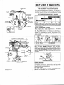
BEFORESTARTING
SPARK PL UG
TO BATTERY VI A S TA R TE R
S WITC H
R E A D TH E OP E R A TIN GIN S TR U C TI O NSO F
TH E E OU IP ME N TTH IS E N GIN E PO WERS
U se a hi gh qual i tydetergentoi l cl assi fi ed" For Ser viceSC,
S D , S E or MS ." D etergentoi l s keepthe engineileaner and
retardthe formati onof gum and varni shdeposit s.Not hing
shoul d be added to the recommendedoi l .
R E C OMME N D E DS A E V IS C OS ITYGRADES
E LE C TR IC
STARTER
MOTOR
TO BATTERY _
V IA A MME TE R
IF FU R N IS H E D
CY LIN D E R
'lf notavailable,
a syntheticoil maybe usedhaving5W-20,5W-30
or 5W-40viscosity.
TO FILL CRANKCASEWITH OIL
Place engine level. Clean area around oil fill before
removi ngoi l fi l l pl ug or oi l mi nder.
OIL FILL P LU G R emove oi l fi l l pl ug or ( opt ional) oilminder. Fill crankcase to point of overflowing. POUR
SLOWLY.Capacity 17rpints (0.6iiters).Replaceoilfill plug
or oi l -mi nder.
1 1 0 V O L T S T A R TER
EXTENDED
OIL FILL.(Optional)
Remove
capanddipstick.
FILL.TO FULL MARK on dipstick,POUR SLOWLY.
Capacity1% pints (0.6 liters).When checkingoil level,
firmlybutslowlyuntilcapbottoms
screwdipstickassembly
on tube.DO NOT OVERFILL.
Dipstickassemblymust be
securelyassembledto tube at all times when engineis
operating.
E X TE N D E DOIL FILL
OIL F IL L PL UG
FORM NO. 270106-3/79
P RI N T E DI N U . S . A .
CHARGE BATTERY
Charge battery before use on engines equipped with
(OPTIONAL) 12V electric starter motor. See equipment
manufacturers recommendations.
FILL FUEL TANK
Use clean, fresh "regular, low-lead or lead-free" grade
gasol i ne.D O N OT MIX OIL W ITH GA S OLI NE.
necessaryw i th chokeopenedsl i ghtl y.Whenenginest ar t s'
open choke gradual l Y .
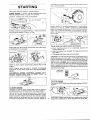
STARTING
S t ar t ,s t or e and fu e l e n g i n e i n a l e v e l p o s i ti on.
E NG I N E - En g i n e ma y b e e q u i p p edw i th ei ther
Choke-A-Maticor Lever-Trolcontrols.
MA NUA L CHO K E: P u l l c h o k e a s i l l u s tra te d .
C HO K E - A - M A T ICa n d L EV ER -T R OL L- Mo vecontrol sas
far as possroletoward "Choke" or Start."
STOP SWITCH: Move STOP switch away from spark plug
as illustrated,if so equipped.
STOP SWITEFI
99e
-'1,1
NOTE:A warm enginerequireslesschokingthan a cold
engine.
NOTE: Engine may not start if controls on powered
equipmentdo not closechokefully. SeeADJUSTMENT
section.
GOVERNOR SPEED GONTB!!--IEJEX: Move
ST" or
"START"positionif so equipped.
/_
,\(
E l ectri cS tarter.On engi nesequi ppedw it h 12 volt st ar t ing
systems, turn key to "START" position or press starter
bui ton.On engi nesequi ppedw i th 120volt st ar t ingsyst em s
oress " On" button ol conductor cord' s int egr al"O n- O f f "
sw i tch. R el easeas soon as engi ne star t s and gr adually
ooen choke.
Tlps to obtaln besl eleclrlc slarler performance
a. Short starting cycles (2 to 3 seconds) provide the
longest battery life.
b. Keegthebatter-y+uUy elarge+. This assuresguick and
easy starts.
c. Disengageload from engine during start'
CAUTION: The 120 volt electric starter is equipped with a
three-prong plug for your safety.The longer prong in this
plug ii connected to the starter motor housing. When.the
staier motor is plugged into the three wire cord supplied'
and the cord is plugged into a properly grounded receptacle, it will protect the user from shock should the starter
motor insulition fail for any reason. lf a longer extension
cord is usedwith this starterit should also havethree-prong
and three-hole Plugs.
Ji',','iXf,?
ffia>
C OR D PLU G
TO STOPENGINE
Turnkeyto "OFF"positionor movecontrolleverto "STOP"
position.
TO START ENGINE
DA NG E R:A LW A YSK EE PH A N D S AN D F E ETC LE A R OF
M O W E RB LA D E OR OT H ER R OT A T IN GM AC H IN E R Y .
Rewind Starter.(Can be usedto startengine if the batteryis
run low or if engine cannot be started electrically.Place
engine controls in "Start" and key in "On" position.)Grasp
starter handle as illustrated and pull out cord rapidly to
overcome compression and prevent kickback. Repeat if
CAUTION: Always remove key from switch when leaving
equipment unattendedor when equipment is not in use'
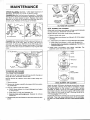
MAINTENANCE
CHECK OIL LEVEL regularly - after each five hours ol
operatio-n-trSFE
orL LEVEL ts MAtNTAINED.
CHANGE OIL after first five hours of operation.Thereafter
change every25 hours of operation.Removeoil drain plug
a n d d r ain oil while e n g i n e i s w a rm. R e p l a c ed ra i n pl ug.
R e mov eoil f ill plug o r o i l -m i n d e ra n d re fi l lw i th n ew oi l of
p ro p e r gr ; de. Repla c eo i l fi l l p l u g o r o i l -mi n d e r.
ASSEIIBLE
ELEH €I{T
SOLIP EXT EIID O
S VER
EOG EO F AIR C tEAIi:R
f
OIL FOA M A IR C LE A N E R
C HAN G E O I L ( G E A R R E D U C T IONo p ti o n a l ) R e moveoi l
l e ve l p lug and oil f il l p l u g . D ra i n o i l e v e ry 1 0 0 h o urs of
o p e rat ion.T o r ef ill,p o u r 1 0 W -3 0o i l i n to fi l l e r h o l e unti l i t
ru n s out lev elc hec k h o l e . R e p l a c eb o th p l u g s .O i l fi l l pl ug
has a vent hole and must be installedon top of gear case
cover.
PLUG
\-----t
r\
DUAL ELEMENTAIR CLEANER
Clean and re-oil foam pre-cleanerat three month intervals
or every 25 hours, whichever occurs first.
NOTE: Service more often under dusty conditions.
1. Remove knob and cover.
2. Removefoam pre-cleanerby sliding it off of the paper
cartridge.
3. a. Wash foam pre-cleanerin liquid detergentand water.
b. Wrap foam pre-cleanerin cloth and squeezedry.
c. Saturatefoam pre-cleanerin engDe oil. Squeezeto
remove excess oil.
4. Install foam pre-cleaner over paper cartridge. Reassemblecover and screw down tight.
I t",'.
TO SERVICEAIR CLEANER
..OIL FOAM'' AIR CLEANER
Clean and re-oil foam element at three month intervalsor
every 25 hours, whichever occurs first.
NOTE: Service air cleaner more often under dusty cond i ti o ns .
1. Removescrew.
2. Removeair cleanercarefullyto preventdirt from entering carburetor.
3. Take air cleaner apart and clean.
a. WASH foam element in a liquid detergentand water
to remove dirt.
b. Wrap foam in cloth and squeezedry.
c. Saturate foam with engine oil. Squeezeto remove
ffi
partsandfastento carburetorsecurelywith
4. Reassemble
screw.
Yearly or every 100 hours, whicheveroccurs first, remove
paper cartridge. (Servicemore often if necessary.)Clean
by tapping gently on flat surface. lf very dirty, replace
cartridge,or wash in a low or non-sudsingdetergent and
warm water solution. Rinsethoroughly with llowing water
from i nsi de out unti l w ater i s cl ear. C artri dgem ust be air
dri ed thoroughl ybeforeusi ng.
CAUTION: Petroleumsolventsare not to be used to clean
cartridge. They may cause deteriorationof the cartridge.
D O N OT OIL C A R TR ID GE .D O N OT U S E P RESSURI ZED
A IR .
CLEAN COOLING SYSTEII - Grass, chaff or dirt may
the air cooling system,
@d
especiallyafter prolongedservicecutting dry grass.Yearly
or every 100 hours, whichever occurs first, remove the
blower housing and clean the areas shown -to avoid overspeeding, overheating and engine damage. Clean more
often if necessary.
CL EAN OUT
CHAF F AN D
DIRT
DANGER: Periodically clean muffler area to remove all
gr as s ,dir t and co mb u s ti b l ed e b ri s .
SPARK PLUG - Clean and reset gap at .030" every 100
hours of operation.
.0 3 0 " ( .7 6m m )
F EEL ERGAUGE
CA UT I O N: Do n o t b l a s t c l e a n s p a rk p l u g . S park pl ug
s hould be c lea n e d b y s c ra p i n g o r w i re b rushi ng and
washing with a commercial solvent.
FINAL ADJUSTMENT
Place governor speed control lever in "FAST" position.
Turn needlevalvein until engine misses(clockwise- lean
mixture) then turn it out past smooth operating point until
engi neruns unevenl y(ri ch mi xture).N ow t ur n needlevalve
to the mi dpoi nt betw eenri ch and l ean so t he engine r uns
smoothly. Next, adiust idle RPM. Rotate throttle countercl ockw i se and hol d agai nst stop. Adjust idle speed
adj usti ngscrew to obtai n 1750 R P M. Releaset hr ot t le engi neshoul d accel eratew i thout hesi tat ionor sput t er ing.
lf engine does not accelerate properly, the carburetor
shoul d be re-adj usted,usual l yto a sl i gh t ly r icher m ixt ur e.
CONTROL ADJUSTMENTS:
Proper choke and speed control operation is dependent
upon proper adjustmentof remotecontrolson the powered
equi pment.
TO C H E C K OP E R A TIONOF C H OK E CO NTRO LS:
Removeair cleaner.Move remotecontrol leverto "CHOKE"
or " S TA R T" posi ti on. C hoke shoul d b e f ully closed as
show n. R epl aceai r cl eaner.
S par k ingc an occ u r i f w i re te rmi n a ld o e s n o t fi t.fi rml yon
spa+t<ptusi or if stop switetr+ib+ates agai+st spark plug.
Reform terminal or repair switch if necessary.
REMOVECOMBUSTION DEPOSITSevery 100-300hours
of oper at ion. R e mo v e c y l i n d e r h e a d a n d c yl i nder head
s hield. S c r ape a n d w i re b ru s h th e c o mb u s tiondeposi ts
from c y linder , c y l i n d e r h e a d , to p o f p i s to n a nd around
valves.Use a soft brush to removedeposits.Re-assemble
gas k et , c y linde r h e a d a n d c y l i n d e r h e a d shi el d. Turn
screws down finger tight with the three longer screws
a r ound t he ex ha u s tv a l v e ,i f s o e q u i p p e d .T o rq uecyl i nder
head screws in a staggeredsequenceto 140 inch pounds
(15. 82Nm ) .
C H OK E LIN K
To Adjust:
P l aceremotecontrol l everon equi pmentin FAST posit ion.
C hokeoperati ngl i nk " A " shoul d be j ustto uchingbellcr ank
l everat " 8." S ee i l l ustrati on.
S P A RK A RRE S T E RE O U IPP EDM U F F L E R - l f engi ne
e n assembl Y ,
remove every 50 hours for cleaning and inspection.
R eplac eif dam a g e d .
ADJUSTMENTS
CARBURETORADJUSTMENTS
Minor carburetor adjustment may be required to compens at elor dif fe re n c e si n fu e l , te m p e ra tu r e,al ti tude or
load.
TO A DJ US T CA R BU R E T O Rw is e unt il it jus t c l o s e s .
T u rn n e e d l eval vecl ock-
CA UT I O N: V alv em a y b e d a ma g e db y tu rn i n g i t i n too far'
Now open need l ev a l v e 1 7 2tu rn s c o u n te rc l ockw i se.Thi s
init ial adjus t m e n tw i l l p e rm i t th e e n g i n e to b e startedand
w ar m ed up pr io r to fi n a l a d j u s tm e n t.
S P E E DC ON TR OLA D JU S TME N T
The acceptabl eoperati ngspeedrangei s 1 800t o3600RPM .
l dl e speed i s 1750 R P M. The manufactur erof t he equip-
ment on whic h th e e n g i n e i s u s e d , s p e ci fi es the top
gov er ned no l o a d s p e e d a t w h i c h th e e n gi ne may be
oper at ed.DO N O T EX C E EDth i s s p e e d .
exceed85%of this rating. Engine power will decrease3%%
for each 1,000feet (304.8m) above sea level and 1o/otor
each 10o above 600 F (16" C ).
ln some areas,local law reqtliresthe use of a resistorspark
pl ug so as to suppressi gni ti on si gnal s.lf an engine was
ori gi nal l yequi ppedw i th ai resi storspark plug, be sur e t o
use the same type of sparf plug for replacement.
TUNE.UP SPECIFICATIONS
Robert
S park P l ug Type
C hl mpi on
Autolite
Bosch
S hort P l ug
235
WSgE
i C J-8
Long P l ug
J-8
295
ResistorShort Plug 7 RCJ-8
245
WSRgE
R esi storLong P l ug ,
R J-8
306
S park P l ug Gap . . .. | . .. .
. . 030" ( . 76 m m )
fgni ti on P oi nt Gap ..r.....
. . 02O "( . 51 m m )
fntakeV al veC l earance ...... .005" -.O O 7"( . 13- . 18 m m )
E xhaustV al veC l earance. . . . . .009"- .011" ( . 23- . 28 m m )
WARNING: For eleitrical safetyalways removecable from
negative (-) side of the battery before attempting any
repairs or maintenance.
S T A NDA RDS P EE DC ON T R OLAD J U ST ME N T
S peed adjus t in gth u m b n u t i s l o c a te d o n top of engi ne.
T o inc r eas es pe e dtu rn th u m b n u t c l o c k w i s e.
S T A N D A R D T U R N T HUM B SCREWCL OCKWISE
GOVERNOR
T O INCREASESPEED
RE M O T ES P E EDC ON T R OL
Controls on powered equipmentshould move speed lever
in direction illustratedto increasespeed. Remotecontrols
m ay be c onnec te dto e n g i n ea t p o i n tsi n d i c a te d.W i retravel
is shown by arrows.
SPEED
REM OT E
12 VOLT
BATTERY
MA NUA L S P E E DC O N T R OL
M ov e k nob as s h o w n to c h a n g e e n g i n e s p e e d.
MANUAL
FR1CT;ON
G O V E R N OR
PUL L KNOB UP T O
INCREASESPEED
rouo[ro
____:l\ / ,
oa(xrc !ao.
"rxr..
IITUL TED IOLETOID
S TOR A GEIN S TR U C TIO NS
E ngi nesto be stored over 30 days shou ld be com plet ely
drai ned of fuel to prevent gum deposit s f or m ing on
essenti alcarburetorparts,f uel f i l ter and t ank.
The use ol a f uel addi ti ve,such as S TA -BlL,or an equival ent, w i l l mi ni mi ze the formati on of fuel gum deposit s
duri ng storage. S uch an addi ti ve may b e added t o t he
gasol i nei n the fuel tank of the engi ne,or t o t he gasoline
i n a storagecontai ner.
a. A l l f uel shoul dbe removedf rom the tank.Runt he engine
unti l i t stoos from l ack of f uel . The sm all am ount of f uel
that remai nsi n the sumo ol the tank should be r em oved
by absorbi ngi t w i th a cl ean,dry cl oth .
b. W hi l e engi ne i s sti l l w arm, drai n oi l f r om cr ankcase.
R efi l lw i th fresh oi l .
c. R emovespark pl ug, pour one ounce (29. 6cc) of engine
oi l i nto cyl i nder and crank sl ow l y t o dist r ibut e oil.
R epl acespark pl ug
G E NE R A LIN FOR M AT I O N
T his engine is a s i n g l e -c y l i n d e r,L -h e a d ,a i r-c ool edtype.
MODEL SERIES100200to 100299
B or e . .
. .. 2 -1 /2" (63.5mm)
S t r ok e
..2 -1 /8 " (53.98mm)
Dis plac em ent. ....
1 0 .4 3c u . i n . (170.9cc)
Horsepower
4.0 max. @ 3600 RpM
Tor que ( F t . Lbs .)
. 5 .9 3 m a x . @ 3050 R P M
MoDELSER|ES
l-99ry ro :t312ee
B or e. .
S t r ok e
Dis plac em ent . ....
H or se p o we r
Torque(Ft.Lbs.)
.2 -9 /1 6 ,,(65.09mm)
.2 -7 /1 6 " (61.91mm)
1 2 .5 7 c u .i n.(206.0cc)
...... $@nax. p io o on e M
. 155 max.E aOOO
neU
The horsepowerrating listed is establishedin accordance
with the Societyof AutomotiveEngineersTest Code - J607.
For practicaloperation,the horsepowerloadingshould not
d. C l ean di rt and chaff from cyl i nder,cylinder head f ins,
bl ow er housi ng,rotati ngscreenand muf f ler ar eas.
6
e. S tore i n a cl ean and dry area.
ER IGGS & S T R A T T ON ENGINESARE M ADE UNDER ONE OR MOR E O F T H E F O LLO W IN GPAT EN IS
2.9 9 9 .4 9 1
3 .1 94.224
3,276,439
3.526.146
3,625,071
28.960
2.9 9 9 ,5 6 2
3 .2 36,937
3,305223
9.572.218
3,650,354
3.831.26E
3114851
3 .2 42.7
41
3,457.804
3,572307
3 745.393
3 882,336
3.118 .4 3 3
3.252.449
3.465.740
3.625,492
3,738.345
3,90r .199
3 1 4 96 1 8
3,961724
3 968,854
3,971,353
3,991,152
D €S I G N
D - 213,475D - 215,7690 -2 2 4 . 1 7 00 -2 4 7 . 1 7 7
PAT
E N TSP E N D I N G
O T H ER