1
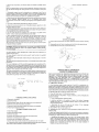
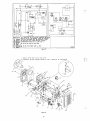
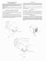
FOR YOUR SAFETY READ BEFORE OPERATING
WARNING: If you do not follow these instructions exactly, a fire
or explosion may result causing property damage, personal injury
or loss of life.
A. T h ~ sappl~ancedoes not have a p~lotIt IS equ~ppedw ~ t han ~ g n ~ t ~dev~ce
on
wh~chautomatically l~ghtsthe burner Do not llght the burner by hand
B BEFORE OPERATING smell all around the appl~ancearea for gas Be sure to
smell next to the floor because some gas I S heav~erthan alr and w~llsettle on the
floor
WHAT TO DO IF YOU SMELL GAS
Ext~ngu~sh
any open flame
Evacuate all persons from the veh~cle
Shut off the gas supply at the gas conta~neror source
Do not touch any electrlc swltch or use any phone or rad~oIn the veh~cle
Do not start the veh~cle'senglne or electrlc generator
-
Contact the nearest gas supplier or qual~fied service technician for repairs.
If you cannot reach a gas supplier or qualified service technician, contact the
nearest fire department
Do not turn on the gas supply until the gas leak(s) has been repaired.
C. Use only your hand to turn the handle on the manual shut off valve. Never use
tools. If the handle will not turn by hand, don't try to repair it, call a qualified
service technician. Force or attempted repair may result in a rfie or explosion.
D. Do not use this appliance if any part has been under water. Immediately call
a qual~fied service technician to inspect the appliance and to replace any part of
the control system and any gas control which has been under water.
OPERATING INSTRUCTIONS
7. Turn on ail electric power to the appliance. These units are for use with LP gas
only. LP gas is heavier then air. Therefore, to better clear out any gas, the heater
should be operated for fvi e (5) minutes with the blower on and the gas off.
I.STOP! Read the safety information above on this label
2. Set the thermostat to lowest setting
3. Turn off all electric power to the appliance.
8. Turn shut-off valve to "ON".
4. The appliance is equipped with an ignition device which automatically l~ghtsthe
burner. Do not try to light the burner by hand.
5. Turn shut-off valve to 'OFF". This furnace is equipped with a valve shut-off
switch. With switch in "OFF" pos~tion,gas will not flow to burner nor will the
furnace operate.
9. Set thermostat to desired setting.
10. If the appliance will not operate, follow the instructions "To Turn Off Gas to
Appliance" and call your service technician or gas supplier. NOTE: If the furnace
should lock-out, the blower will go off in 5 minutes and remain off until unit is reset
by reactivating thermostat.
6. Wait five (5) minutes to clear out any gas. Then smell for gas including near
the floor. If you then smell gas. STOP! Follow'B" in the safety information above
on this label. If you don't smell gas, go to next step.
TO TURN OFF GAS TO APPLIANCE
I.Set the thermostat to lowest setting, then move lever to " O F F position.
3. Turn shut-off valve to "OFF". Do not force.
2. Turn off all electric power to the appliance if service is to be performed.
MAINTENANCE AND CLEANING
i n which i t was shipped from the factory or if the appliance i s not used
solely for its intended purpose or i f appliance is not maintained i n
accordance with the instructions i n this manual, then the risk of a fire
andlor the production of carbon monoxide exists which can cause
CAUTION: Label all wires beforedisconnecting for
Proper polarity
must be observed so the furnace motor will run with the proper direction of
rotation to insure correct air delivery. (See wiring diagram.)
CAUTION: Label all wires prior t o disconnection when servicing controls.
Wiring errors can cause improper and dangerous furnace operation.
Always verify proper operation of furnace after servicing.
Your furnace should be inspected by a qualified service agency yearly
before turning the furnace on. Particular attention should be given t o the
following items.
I.lnspect furnace installation and vent termination to be sure furnace is properly
secured in place (See Installation Instructions), that vent terminates to the
atmosphere, and that vent tubes overlap properly (See Installing Vent Assembly).
2. lnspect chamber and venting to assure that these components are physically
sound, without holes or excessive corrosion and that the installation andlor
reinstallation is in accordance with Suburban's Installation Instructions.(Reference
installation manual supplied with furnace.)
WARNING! It i s imperative that the products of combustion be properly
vented t o atmosphere and that all combustion air supplied to burner be
drawn from outside atmosphere.
3. Check the base on which furnace is mounted, Be sure it is physically sound,
void of any sagging, deterioration, etc.
4. Inspect furnace. the ventinq and the qas p
. i.~ i n- oto furnace for obvious sions of
deterioration. Correct any defects at once.
5. lnspect main burner. To properly inspect burner, it must be removed (See
Figure 8.) If excessive rust and corrosion are present on burner surface, the
burner must be cleaned or replaced. The burner may be cleaned with a steel wire
brush and the burner ports and venturi blown clean using compressed air.
If the main burner has been allowed to operate with a high yellow flame, a soot
formation may be deposited inside the combustion chamber. The carbon deposit
may be of such quantity that cleaning will be necessary.A vacuum cleaner is deal
'lean Out any
deposit in the combustion chamber'
6. Inspect combustion chamber for restrictions in exhaust or intake. It is
imperative that the flow of intake combustion air and the flow of exhaust gases
being expelled to the outside atmosphere not be obstructed, Any soot or loose
air.
debris should be blown out usino
- COm~ressed
,
7. lnspect all gaskets. If any gaskets show signs of leakage or deterioration.
replace them Safe operation of the furnace depends on all gaskets being tight.
8. lnspect return air inlet openings to the furnace. Remove any restrictions to
assure adequate air flow.
You, as the ownerluser, should inspect the furnace monthly during the
heating season for presence of soot on vent. Operating the furnace under this
condition could lead to serious property damage, personal injury or loss of life. If
soot is observed on the vent, immediately shut the furnace down and contact a
qualified service agency.
Listed below are several safety related items that you should follow during the
heating season to assure continued safe operation of the furnace.
1. lnspect furnace venting. Venting must be free of obstructions, void of soot and
properly terminated to the atmosphere.
I WARNING! Do not install screens over the vent for any reason. Screens I
will become restricted and cause unsafe furnace operation. Accessories
are being marketed for RV products which we do not recommend. For
y o u r safety, only factory authorized parts are t o be used on your furnace.
2. Periodically observe the main burner flame to assure it is burning with a hard
blue flame with well defined burner ports (See Figure 6). If flame appears yellow
or burner has a lazy flame, shut furnace down and contact a qualified service
person.
FURNACE ASSEMBLY REMOVED
/ A
NOTE: To observe flame, remove front discharge grille. Operation of burner can
then be observed through the viewing window on front of chamber. (See Flgure
7.)
3. Periodically inspect the vent for obstructions or presence of soot Soot is
formed whenever combustion is incomplete. This is your visual warning that the
furnace is operating in an unsafe manner. If soot is present, immediately shut
furnace down and contact your dealer or a qualified service person
4. Keep furnace clean. More frequent cleaning may be required due to excessive
lint from carpeting, bedding material, etc. It IS imperative that control
compartments, burners and circulating air passageways of the appliance be kept
clean
5. The motor is permanently lubricated and requires no oiling
6. Keep the furnace area clear of any combustible materials, gasoline or other
flammable vapor and liquids.
7. Before operating furnace, check the location of the furnace vent to make sure
it will not be blocked by the opening of any door on the traller. If it can be blocked,
do not operate the furnace wlth the door open.
8. Do not restrict the flow of combustion air or the warm air circulation to the
furnace. To do so could cause personal injury andlor death.
9. Never operate the furnace if you smell gas. Do not assume that the smell of
gas ~n your RV is normal. Any time you detect the odor of gas, it IS to be
considered life threatenlng and corrected immediately. Extinguish any open
flames including cigarettesand evacuate all persons from the vehicle. Shut off gas
supply at LP gas bottle. (See safety notice on front cover of this manual.)
10. lmmedlately shut furnace down and call a service agency if furnace cycles
erratically or delays on ignition.
WARNING! Should overheating occur, o r the gas supply fail to shut off,
shut off the manual gas valve to the appliance before shutting off the
electrical supply.
11. Never attempt to repair damaged parts. Always have them replaced by a
qualified service agency.
12. Never attempt to repair the furnace yourself Seek the help of a qualified
service person
13. Clothing or other flammable material should not be placed on or near the
appliance.
14. Always follow the Operating Instructions. Do not deviate from the stepby-step
procedures
15. In any installat~onIn wh~chthe vent of this appliance can be covered due to the
construction of the RV or some special feature of the RV such as slide out, pop-up
etc. always insure thal the appliance cannot be operated by setting the thermostat
to the positive "OFF" position and shutting off all electr~caland gas supply to the
appliance Never operate furnace with vent covered.
16. When cons~deringadd-on rooms, porch or patio, attention must be glven to the
venting of your furnace. For your safety, do not terminate furnace vent inside addon rooms, screen porch or onto patios. Doing so will result in products of
combustion being vented Into the room or occupied areas.
Figure 7
TO REPLACE BURNER
I . Center orifice end of burner over orifice, slide other end over burner mounting
pin.
2. Reassemble nut over burner mounting stud until it is firmly against burner.
3. Reinstall burner access door and secure with nuts.
:x.,",.:*
v;-.'
SERVICE HINTS, DIAGNOSIS &
CORRECTIVE MEASURES
INSTALLATION SHOULD BE DONE BYAQUALIFIED SERVICE PERSON. THE
APPLIANCE SHOULD BE INSPECTED BEFORE USE AND AT LEAST
ANNUALLY BY A PROFESSIONAL SERVICE PERSON. MORE FREQUENT
CLEANING MAY BE REQUIRED DUE TO EXCESSIVE LINT FROM
CARPETING. BEDDING MATERIAL. ETC. IT IS IMPERATIVE THATCONTROL
COMPARTMENTS. BURNERS AND CIRCULATING AIR PASSAGEWAYS OF
A. COMPLAINT
Figure 6
a:::.\
Figure 8
- NO HEAT
I. Check electrical supply to make sure that 12 volt D.C. is available at unit
Battery must be charged. If battery is low, there may be sufficient power to run the
blower but not enough to run the blower at full speed. If blower does not run at it's
prescribed speed, the microswitch cannot engage and gas will not flow to the main
burner. Be sure the connections to the voltage lines in the terminal block are tight.
2. Manually rotate fan to make sure motor is free to turn
3. Check for blown fuse in 12 Volt circuit to furnace.
TO REMOYE FURNACE FOR SERVICE
I . Remove the front grille.
2. Disconnect wiring
3. Disconnect gas supply. (Be sure gas supply to the unit is turned off.)
4. Remove screws securing furnaces to cabinet
5. Remove the vent cap screws (outside) and remove vent assembly.
6. Pull furnace fonvard and remove.
TO REMOVE BURNER 8, GAS VALVE
I. Shut off gas supply
2. Disconnect electrical supply
3. Remove front grille.
4. Remove nuts holding burner access door and remove door.
5. Remove nut holding burner in place.
6. Raise burner off mounting pin and remove.
7. Burner orifice may now be serviced with long extension and 112 socket
8. To replace gas valve, remove manifold mounting screws and remove manifold
from furnace. Place manifold in a vise to remove gas valve.
4. SHORT CIRCUIT CHECKOUT: if fuses are blown, a short is indicated and
should be checked.
a. Turn off all appliances including furnace.
b. Install an ammeter on the positive (+) lead of the battery. Amperage
reading should be 0. If an amperage reading is noted, a short exists in the
vehicle electrical system.
c. Disconnect the red (+) DC lead at the furnace. If the amperage
continues, the short is exterior to the furnace.
5. GAS SUPPLY: Be sure gas supply is on.
6. THERMOSTAT OFF: Check to be sure thermostat is properly wired and is
calling for heat.
7. MALFUNCTIONING MICROSWITCH: Be sure the microswitch is moving far
enough to close itscontacts. If the switch is not closing, clean any dust or dirt from
the actuator pin. Other reasons for switch not operating are:
a. Insufficient fan speed (slow motor due to low charged battery, faulty
motor or lint and dust accumulation restricting return air to furnace). Check
wiring in accordance with units wiring diagram to assure that the proper
polarity of the 12 Volt DC power supply is observed. On certain models this
polarity must be observed so the motor will run the proper direction of
rotation to insure correct air delivery
b. Faulty M~croswltchReplace swltch ~fvalve does not open when swltch
1s engaged Sw~tchshould also be replaced ~f battery IS fully charged and
wlth the fan motor running at top speed the switch falls to engage wlthln 3
to 4 seconds
NOTE To se~viceswitch, heatlng assembly must be pulled but
8. GAS CONTROL VALVE: Wlth test light, check valve terminals. If voltage IS
present but valve 1s not opening (when microswitch engages), replace control
valve.
9. FAN NOTOPERATING Check for burned-out motoror loosewiring terminals
10. DEFECTIVE FAN RELAY: Relay may be at fault if motor fails to start when
thermostat calls for heat. Thls can be suspected if the thermostat is ra~sedand the
motor falls to operate within 60 seconds.
- EXCESSIVE NOISE
1. Motor or blade out of balance. Replace motor or blade.
B. COMPLAINT
2. Motor hum Replace motor
-
C. COMPLAINT ERRATIC FAN OPERATION
A loose terminal or a defective relay may cause the motor to cycle off while the
thermostat is calling for heat. An outage will occur because the blower is not
purging the system of combustion products.
HIGH ALTITUDE DERATION
These units are certified by the Canadian Gas Association for operation without
modification at altitudes up to 4500 feet.
Operation at increased elevations requirederation of4% for each 1000 feet above
sea level. Example: At 8.000 feet. derate furnace 32%.
If the unit is not properly derated the following cond~tionswill exist:
I.Due to the lack of sufficient oxygen for proper combustion, carbon monoxide
will be produced and exhausted through the vent. Entry of these fumes into the
vehicle (due to improper installation of the vent or through another opening in the
vehicle (exterior) could create a hazardous condition which could endanger the life
of anyone exposed to these fumes for a prolonged period of time.
2. Due to ~ncompletecombustion of LP gas at the burner, the actual heat output
of the furnace will be considerably less than the ratlng of the unit Fuel which is not
burned will be wasted.
If the unit is properly derated. !twill produce approximately the same amount of
heat at higher elevations, but will do so with considerably less fuel.
Consult with local gas company, your dealer or RV service agency for proper
orifice size when derating unit. Change out of orifice should be done by your
dealer or a qualified service agency.
DIRECT SPARK IGNITION SYSTEM
The direct spark ignition system consists of a solid state printed circuit control
module, an electrode assembly, a 12 volt gas control and connecting high and low
voltage wires.
To ignlte the burner, it 1s necessary only to set the thermostat above room
temperature. The thermostat, in series with the microswitch, powers the ignitor to
simultaneously open the main burner valve and provide the ignition spark. Should
the flame not be established within a period of 15 seconds, the system provides
safety shut-down
Electronic flame sensing circuitry in the ignitor detects the presence or absence
of main burner flame. If the flame is not established during the Flame Establishing
Period (6 seconds), the system closes the gas valve and locks out. To reactivate
ignition, if lock-out has occurred, set the thermostat to the ' O F F position for4 to
5 seconds, then reset to the 'ON' position.
TROUBLE SHOOTING GUIDE
CAUTION: Servicing this device should only be performed by a qualified
serviceman with due regard for safety as improper actions could result in
a hazardous condition, resulting i n serious injury or death.
WARNING! Do not apply power to control module unless wiring
connections are complete and electrode is properly grounded. Use extra
caution i n areas where high voltage is present.
A. Input Polarity: If a spark is present and the gas valve opens but the system
shuts down after the trial period, check input voltage for proper polarity.
B. Grounding: It is essential to proper operation thal the system be properly
grounded. If a spark is present and the gas valve opens but the system shuts
down after the trial for ignition period, check for proper ground. The following items
should be checked:
1. Ground screw connecting black motor lead.
2. The burner must be securely fastened to mounting pin in heat chamber.
C. Wiring: Check all wiring for proper and secure connections. Be sure the AMP
connector is fully engaged on the control board. Check the high voltage wire for
proper connection at both ends. Clean any corrosion that may interfere with good
electrical contact.
D. High Voltage Malfunction: If during the trial for ignition, the spark is
intermittent and the valve may or may not open, the following should be checked:
I.Electrode spark gap -should be 118" + 1132".
2. Ceramic housing - check for cracks.
3. Electrode lead wires - check for cracks or breaks.
E. Valve Malfunction: If there is power to the gas valve and a spark during the
trial for ignition, but the valve will not open, check the valve for an open coil or
other malfunction.
F. Erratic Operation: If the system operates properly for a period of time but
randomly shuts down during the duty cycle, or will not operate during cold starts.
check the flame proving circuit (sensor wire) with a D.C. Microamp Meter. The
current may cause nuisance tripping. If this condition is experienced, the electrode
location should be checked to make sure the sensor electrode is in the flame.
G. The solid state control module is not field repairable. Any modifications or
repairs will invalidate the warranty and agency certifications.
TEMPERATURE RATING
OF AT LEAST 105' C.
Figure 10
U K D t H USING NO. L I S l t U ON VENT
Figure 11
6
REPLACEMENT PARTS LIST
MODEL OD-17DSI
Only factory authorized parts are to be used. Do not attempt to repair defective parts .
When ordering repalr parts from your dealer. a Suburban Serv~ceCenter or a distributor. always
give the following information
1. Part Number (Not ltem No.)
2. Part Description
3. Model and Serial Number of Furnace
4 . Number of Parts Reauired
ltem
NO.
1
2
3
4
5
6
7
8
9
10
11
12
Part
Description
Number
.
.
. . . . . . . . . . . . . . . . . . . . . . . .
161154
Thermostat .
. . . . . . . . . . . . 121717
Screw (2 Required) . . .
. . . . . . . . . . . . .
Brace . Combustion Air Houslng . . . . . . . . . . . . . . . . . . . . . . . . . . . 062945
Intake Air Cup Assembly . . . . . . . . . . . . . . . . . . . . . . . . . . . . . . . 051288
390536
. . .
. . . .
Housing Combustion Air (Front) . . . .
. . . . . . . . . . . . . . . . 070862
Gasket Combustion Air Housing (Front)
Nut #2-56 (2 Required) . . . . . . . . . . . . . . . . . . . . . . . . . . . . . . . . . 121951
. . . . . . . . . . . . . . . . . . . . . . . . . . . . . . . . . . . . . . .
Microswitch
231930
Screw (2 Required) . . . . . . . . . . . . . . . . . . . . . . . . . . . . . . . . . . . . . . . . 121247
. . . . . . . . . . 390537
Panel Assembly, Combustion Air . . . . . . . . . . . . . . . .
Combustion Air Housing Rear . . . . . . . . . . . . . . . . . . . . . . . . . . . . . . . . . .
390535
Vent Assembly (Order by Part No l~stedon vent assembly supplied with
furnace . If Part No. label is not attached, contact SUBURBAN MFG. CO.)
Screw (8 Required) . . . . . . . . . . . . . . . . . . . . . . . . . . . . . . . . . . . . . . . . 121717
Screw . . . . . . . . . . . . . . . . . . . . . . . . . . . . . . . . . . . . . . . . . . . . . . . . .
121715
Wheel.CombustionAir . . . . . . . . . . . . . . . . . . . . . . . . . . . . . . . . . . . . . 350126
070906
Gasket, Combustion Air Housing (Rear) . . . . . . . . . . . . . . . . . . . . .
Gasket, Burner Tunnel . . . . . . . . . . . . . . . . . . . . . . . . . . . . . . . . 070859
Gasket, Motor . . . . . . . . . . . . . . . . . . . . . . . . . . . . . . . . . . . . . . . . . 070849
Motor . . . . . . . . . . . . . . . . . . . . . . . . . . . . . . . . . . . . . . . . . . . . . . . 231916
. . . . . 350125
Impeller Room Air . . . . . . . . . . . . . . . . . . . . . .
. . . . . . . . . . . . . . . . . . . . . . . . . . . . . . . . 051 159
Burner, Tunnel Assembly
. . . . . . . . . . . . . . . . . 010886
Burner . . . . . . . . . . . . . . . . . . . .
Gasket, Manifold . . . . . . . . . . . . . . . . . . . . . . . . . . . . . . . . . . . . . . . 070847
Screw (3 Required) . . . . . . . . . . . . . . . . . . . . . . . . . . . . . . . . . . . . . 121717
Manifold with Orifice . . . . . . . . . . . . . . . . . . . . . . . . . . . . . . . . . . . . . 171624
Orifice . . . . . . . . . . . . . . . . . . . . . . . . . . . . . . . . . . . . . . . . . . . . . . . . . . . 180130
Gasket Burner Tunnel (Chamber End) . . . . . . . . . . . . . . . . . . . . . . . . . . . . . . 070848
Cabinet Back Assembly . . . . . . . . . . . . . . . . . . . . . . . . . . . . . . . . . . . . . . 101422
Screw (2 Required) . . . . . . . . . . . . . . . . . . . . . . . . . . . . . . . . . . . . . . . . . . . 121357
S c r e w l o - 1 6 x 1 . . . . . . . . . . . . . . ; . . . . . . . . . . . . . . . . . . . . . . . . . . 121936
Insulator Module Board . . . . . . . . . . . . . . . . . . . . . . . . . . . . . . . . . . . . . . . . .070807
Module Board . . . . . . . . . . . . . . . . . . . . . . . . . . . . . . . . . . . . . . . . . . . . . .520820
Spacer.Nylon . . . . . . . . . . . . . . . . . . . . . . . . . . . . . . . . . . . . . . . . . . . 063422
Bushing Strain Relief . . . . . . . . . . . . . . . . . . . . . . . . . . . . . . . . . . . . . . . 230216
Screw (2 Requ~red). . . . . . . . . . . . . . . . . . . . . . . . . . . . . . . . . . . . . . . . .121717
Cover.ModuleBoard . . . . . . . . . . . . . . . . . . . . . . . . . . . . . . . . . . . . . . . . . . .090539
Switch ONIOFF . . . . . . . . . . . . . . . . . . . . . . . . . . . . . . . . . . . . . . . . . . . . . 232351
BracketManifold . . . . . . . . . . . . . . . . . . . . . . . . . . . . . . . . . . . . . . . . . . . 063235
Screw (2 Required) . . . . . . . . . . . . . . . . . . . . . . . . . . . . . . . . . . . . . . . . . . . . 121717
Valve . . . . . . . . . . . . . . . . . . . . . . . . . . . . . . . . . . . . . . . . . . . . . . . . . . . . 161071
GasFitting . . . . . . . . . . . . . . . . . . . . . . . . . . . . . . . . . . . . . . . . . . . . . . . . . . .170374
Bushing.Universal . . . . . . . . . . . . . . . . . . . . . . . . . . . . . . . . . . . . . . . . . . .070362
Bushing.Open1Close . . . . : . . . . . . . . . . . . . . . . . . . . . . . . . . . . . . . . . . . . . . . 070855
Bracket Cabinet Tie-Down (4 Required) . . . . . . . . . . . . . . . . . . . . . . . . . . . 062942
Gasket(E1ectrode) . . . . . . . . . . . . . . . . . . . . . . . . . . . . . . . . . . . . . . . . . . . . . . 070163
Electrode . . . . . . . . . . . . . . . . . . . . . . . . . . . . . . . . . . . . . . . . . . . . . . . . . . . 232784
Screw 8 X 318 (6 Required) . . . . . . . . . . . . . . . . . . . . . . . . . . . . . . . . . . . . . . . 120158
GrilleAssembly . . . . . . . . . . . . . . . . . . . . . . . . . . . . . . . . . . . . . . . . . . . . . . . .030966
Screw 10 - 24 x 112 (2 Required) . . . . . . . . . . . . . . . . . . . . . . . . . . . . . . . . . 121877
Door.BurnerAccess . . . . . . . . . . . . . . . . . . . . . . . . . . . . . . . . . . . . . . . . . . .031172
. 151
Gasket Burner Access Door . . . . . . . . . . . . . . . . . . . . . . . . . . . . . . . . . . . . 071
Screw 8-32 X 318 (Black) (2 Required) . . . . . . . . . . . . . . . . . . . . . . . . . . . . . .121407
.
.
.
.
.
.
.
.
.
.
.
.
.
.
.
.
.
.
.
.
.
.
.
.
.
.
.
.
.
.
.
.
.
.
.
.
.
.
.
.
.
.
.
.
Bracket Limit Switch
062944
Chamber Assembly (Comes with Item No. 4) . . . . . . . . . . . . . . . . . . . . . . . . . 021 178
Limitswitch . . . . . . . . . . . . . . . . . . . . . . . . . . . . . . . . . . . . . . . . . . . . . . . 231768
Screw (2 Required) . . . . . . . . . . . . . . . . . . . . . . . . . . . . . . . . . . . . . . . . . . . . 121502
Cabinet Wrap Assembly . . . . . . . . . . . . . . . . . . . . . . . . . . . . . . . . . . . . . . .101890
Bushing . . . . . . . . . . . . . . . . . . . . . . . . . . . . . . . . . . . . . . . . . . . . . . . . . . . . 070856
Screw (2 Required) . . . . . . . . . . . . . . . . . . . . . . . . . . . . . . . . . . . . . . . . . . . 121717
Fuseholder(NotShown) . . . . . . . . . . . . . . . . . . . . . . . . . . . . . . . . . . . . . . . . 231908
Electrode Wire (Not Shown) . . . . . . . . . . . . . . . . . . . . . . . . . . . . . . . . . . . . . . 231783
Splicer . . . . . . . . . . . . . . . . . . . . . . . . . . . . . . . . . . . . . . . . . . . . . . . . . . . . . . . 230714
Screw(2Required) . . . . . . . . . . . . . . . . . . . . . . . . . . . . . . . . . . . . . . . . . . . . . 121244
Nut 10-247 Keps (2 Required) . . . . . . . . . . . . . . . . . . . . . . . . . . . . . . . . . . .120717
Screw 10-24 X 112 (2 Required) . . . . . . . . . . . . . . . . . . . . . . . . . . . . . . . . . . 121459
.
.
.
.
.
.
.
.
.
.
.
TWO YEAR LIMITED WARRANTY
SUBURBAN RECREATIONAL VEHICLE FURNACE
TWO YEAR LIMITED WARRANTY
This Suburban product is warranted to the original purchaser to be free from defects in material and workmanship under normal use and
maintenance for a period of two years from date of purchase whether or not actual use begins on that date. It is the responsibility of the
consumerlowner to establish the warranty period. Suburban does not use warranty registration cards for its standard warranty. You are required
to furnish proof of purchase date through a Bill of Sale or other payment record.
Suburban will replace any parts that are found defective within the first two years and will pay a warranty service allowance directly to the
authorized Suburban Service Center at rates mutually agreed upon between Suburban and its authorized service centers. Replacement parts
will be shipped FOB the shipping point within the Continental United States. Alaska and Canada to authorized service centers performing such
repairs. Before havinq warranty repairs made, confirm that the service aqency is an authorized service center for Suburban. DO NOT PAY THE
SERVICE AGENCY FOR WARRANTY REPAIRS; SUCH PAYMENTS WlLL NOT BE REIMBURSED.
For warranty service, the ownerluser should contact the nearest authorized Suburban Service Center, advising them of the model and serial
numbers (located on the furnace) and the nature of the defect. Transportation of the unit to and from the Service Center andlor travel expenses
of the Service Center to your location is the responsibility of the ownerluser. A listing of authorized Service Centers is included in the owner's
packet supplied with the furnace and a current listing may be obtained from Suburban. If you cannot locate an authorized service center locally,
the service agency chosen to perform warranty repairs must contact our Service Department at 423-775-2131 for authorization. Unauthorized
repairs made will not be paid by Suburban.
THREE YEAR LIMITED WARRANTY ON HEAT EXCHANGER
The furnace heat exchanger is further warranted to be free from defects in material and workmanship during the third through fifth year after the
date of original purchase. A replacement heat exchanger will be provided under the same conditions as stated in the two year warranty EXCEPT
no labor reimbursement will be provided.
LIMITATION OF WARRANTIES
ALL IMPLIED WARRANTIES (INCLUDING IMPLIED WARRANTIES OF MERCHANTABILITY) ARE HEREBY LIMITED IN DURATION TO THE
PERIOD FOR WHICH EACH LIMITED WARRANTY IS GIVEN. SOME STATES DO NOT ALLOW LIMITATIONS ON HOW LONG AN IMPLIED
WARRANW LASTS SO THE ABOVE LIMITATIONS MAY NOTAPPLY TO YOU. THE EXPRESSED WARRANTIES MADE IN THlS WARRANTY
ARE EXCLUSIVE AND MAY NOT BE ALTERED, ENLARGED, OR CHANGED BY ANY DISTRIBUTOR. DEALER OR OTHER PERSON
WHOMSOEVER.
SUBURBAN WlLL NOT BE RESPONSIBLE FOR:
1. Normal maintenance as outlined in the installation, operating and service instructions owner's manual including cleaning of component parts;
such as, orifices and burners.
2. Initial checkouts and subsequent checkouts which indicate the furnace is operating properly, or diagnosis without repair.
3. Damage or repairs required as a consequence of faulty or incorrect installation or application not in conformance with Suburban instructions.
4. Failure to start andlor operate due to loose or disconnected wires; water or dirt in controls, fuel lines and gas tanks; restriction or alteration
of return air circulation; low voltage.
.
5. Routine adjustments that may be required to the thermostat, electrode and burner.
6. Costs incurred in gaining access to the furnace.
7. Parts or accessories not supplied by Suburban.
8. Freight charges incurred from parts replacements.
9. Damage or repairs needed as a consequence of any misapplication, abuse, unreasonable use, unauthorized alteration, improper service,
improper operation or failure to provide reasonable and necessary maintenance.
10. Suburban products whose serial number has been altered, defaced or removed.
11. Suburban products installed or warranty claims originating outside the Continental U.S.A., Alaska, Hawaii and Canada.
12. Damage as a result of floods, winds, lightning, accidents, corrosive atmosphere or other conditions beyond the control of Suburban.
13. ANY SPECIAL, INDIRECT OR CONSEQUENTIAL PROPERTY. ECONOMIC OR COMMERCIAL DAMAGE OF ANY NATURE
WHATSOEVER. Some states do not allow the exclusion of incidental or consequential damages, so the above limitation may not apply to you.
NO REPRESENTATIVE. DEALEROROTHER PERSON ISAUTHORIZEDTOASSUME FOR SUBURBAN MANUFACTURING COMPANY ANY
ADDITIONAL, DIFFERENT OR OTHER LlABlLlW IN CONNECTION WITH THE SALE OF THlS SUBURBAN PRODUCT.
This warranty gives you specific legal rights, and you may also have other rights which vary from state to state.
IF YOU HAVE A PRODUCT PROBLEM
FIRST:
If your RV has its original furnace and is still under the RV manufacturer's warranty, follow the steps described in your RV owner's manual.
SECOND:
Contact a conveniently located recommended Suburban Service Center. Describe to them the nature of your problem, make an appointment, if
necessary, and provide for delivery of the furnace to the selected service center.
THIRD:
For the location of the nearest service center, refer to the listing provided or contact:
Suburban Manufacturing Company
Customer Service Department
Post Office Box 399
Dayton. Tennessee 37321
For future reference, you should record the following information
(423) 775-2131, Ext. 1
MODEL NUMBER
SERIAL NUMBER
STOCK NUMBER
DATE OF PURCHASE
Part Number 203471
10-1 6-03
uburban
Bs
SUBURBAN MANUFACTURING COMPANY
P o s t Office B o x 399
Dayton, Tennessee 37321
Manufacturing Company
OWNERS' INFORMATION MANUAL
DIRECT SPARK IGNITION
For Model DD-17DSI
CtAnFltO
This book contains instructions for operating and maintaining the
furnace. Keep with unit at all times.
Should you require further information, contact your dealer or nearest
Suburban Sewice Center.
WARNING! Installation of this appliance must be
made in accordance with the written instructions
provided in this manual. No agent, representative
or employee of Suburban or other person has the
authority to change, modify or waive any provision
of the instructions contained in this manual.
Due to high temperatures, the unit should be located out of traffic and
away from furniture and draperies.
Children and adults should be alerted to the hazards of high surface
temperatures and should stay away to avoid burns or clothing ignition.
Young children should be carefully supervised when they are in the same
room as the unit.
Clothing or other flammable material should not be placed on or near the
unit.
Any safety screen or guard removed for servicing the unit must be
replaced prior to operating the unit.
The area around the unit must be kept clear from combustible materials,
gasoline and other flammable vapors and liquids.
Installation and repairs should be done by a qualified service person. The
unit should be inspected before use and at least annually by a qualified
service person. More frequent cleaning may be required due to excessive
lint from carpeting, bedding material, etc. It is imperative that control
compartments, burners, and circulating air passageways of the unit be
kept clean.
WARNING: If the information in this manual is not
followed exactly, a fire or explosion may result
causing property damage, personal injury or loss
Do not store or use gasoline or other flammable
vapors and liquids in the vicinity of this or any
other appliance.
WHAT TO DO IF YOU SMELL GAS
Extinguish any open flame.
Evacuate all persons from the vehicle.
Shut off the gas supply at the gas container or
source.
Do not touch any electrical switch, or use any
phone or radio in the vehicle.
Do not start the vehicle's engine or electric
generator.
Contact the nearest gas supplier or qualified
service technician for repairs.
If you cannot reach a gas supplier or qualified
service technician, contact the nearest fire
department.
Do not turn on the gas supply until the gas
leak(s) has been repaired.
Installation and service must be performed by a
qualified installer, service agency or the gas
supplier.
Form No. 2571-C
WARNING!
This unit must be serviced only by a qualified
serviceman. Modification of the appliance can be
extremely hazardous and could lead to serious
injury or death.
Fuel burning appliances generate toxic flue
products. Modification or improper maintenance
can cause carbon monoxide in deadly amounts. To
prevent this, maintain appliance in safe operating
condition.
DO NOT Block or modify any combustion air or
flue gas passageways.
DO NOT Add any devices or accessories to this
appliance except those specifically
authorized by Suburban Manufacturing
Co.
DO NOT Install screens over the vent for any
reason. Screens will become restricted
and cause unsafe furnace operation.
Accessories are being marketed for RV
products which we do not recommend.
For your safety, only factory authorized
parts are to be used on your furnace.
ALWAYS Consult a qualified serviceman for any
problems or questions you may have
pertaining to this appliance.
ALWAYS Inspect the appliance before starting a
new heating season, paying special
attention to combustion air, flue gas
passageways and gas lines.
LIMIT SWITCH
OPERATING INSTRUCTIONS
Direct Spark Ignition
WARNING! Be sure the furnace and all ignition systems are "OFF" during
any type of refueling and while vehicle is i n motion or being towed.
IMPORTANT: Failure to follow these lighting instructions exactly may result
i n damage to the unit.
WARNING! Do not operate furnace while vehicle i s i n motion or being
towed.
The purpose of the limit control is to turn off the gas to the main burner if for any
reason the furnace becomes abnormally hot If the clrculating air is blocked, even
partially, the limit control w ~ lfunct~on
l
and cause the main burnerto cycle. Ifcycling
of the Ilmtt control occurs, the clrculating air passage should be thoroughly
cleaned.
If the limit control IS damaged, it cannot be repalred It must be replaced w~tha
new one.
CAUTION: Never short across or bypass the limit control even for only
temporary operation.
MICROSWITCH
SEQUENCE OF NORMAL OPERATION
The rnicrosw~tchhas two purposes:
1. When the thermostat calls for heat, the fan motor IS energized
2. As the fan motor reaches approximately 75% of ~ t snormal r p m. (within 1 to
2 seconds) the microswltch, in response to the air flow, will engage, allowing
current flow to the module board
3. Aner a 15 - 30 second delay. the gas valve will open and allow gas to the main
burner. The spark produced from the lgnltor electrode ign~testhe main burner
4. When the thermostat is satisfied or turned back, thegasvalve will close and the
flame on the main burner will go out. The blower will continue to run for a short
period of time and w ~ lthen
l
shut off. The purpose of this is to remove most of the
remaining gases and heat from the heat exchanger.
I.It is an 'air prover". It operates in response to the flow of air generated by the
fan Hence. ~ffor any reason the air from the fan IS not sufficient, the switch will not
operate One cause of insuffic~entair IS a slow motor caused by low voltage.
2. The sw~tchallows time for the blower to pull in a sufficient amount of air to
support combust~onbefore i! engages. Once it engages, thegas valve opens, gas
flows to the maln burner and lgnitlon occurs
BLOWER ASSEMBLY
One motor is used to drive both the combustion air wheel and the circulating air
fan blade. Although one motor drives both, the wheel and fan blade are separate.
The combustion air blower is sealed so as to allow no passage of alr between it
and the circulating room air fan. The combustion air blower draws air from the
outside atmosphere, discharges it into the combustion chamber, and forces the
combust~onproducts out the exhaust tube The circulat~ngroom air fan blade pulls
return air in and forces it across the heat chamber discharging it into the area to
be heated.
Figure 2
Figure I
_._,-- CWWusrlON BcoWER AND
/'
GAS FIT1NG
,/"
c
GAS COhTROL
Figure 5
FAN ASSEMBLY