1
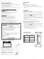
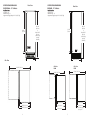
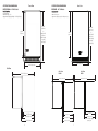
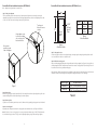
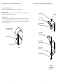
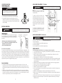
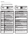
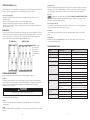
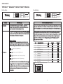
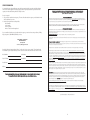
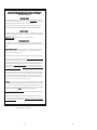
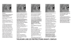
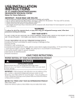
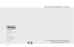
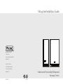
Viking Use/Installation Guide
Viking Range Corporation
111 Front Street
Greenwood, Mississippi 38930 USA
(662) 455-1200
For product information
call 1-888-VIKNG1 (845-4641)
or visit the Viking Web Site at
vikingrange.com
F20725A EN
Undercounter/Freestanding Refrigerated
Beverage Centers
(071610)
IMPORTANT - PLEASE READ AND FOLLOW
GENERAL INFORMATION
•
•
•
•
•
Unpack
1. Remove banding from bottom of carton. Lift carton up and off of the unit.
2. Remove all tape and packaging material from the outside and inside of the cabinet.
3. Keep all carton packaging until your refrigerated beverage center has been thoroughly inspected and found to be in
good condition.
Before beginning, please read these instructions completely and carefully.
Do not remove permanently affixed labels, warnings, or plates from the product. This may void the warranty.
Please observe all local and national codes and ordinances.
Please ensure that this product is properly grounded.
The installer should leave these instructions with the consumer who should retain for local inspector’s use and for
future reference.
A GFI shall be used if required by NFPA-70 (National Electric Code), federal/state/local
laws, or local ordinances.
• The required use of a GFI is normally related to the location of a receptacle with respect to
any significant sources of water or moisture.
• Viking Range Corporation will NOT warranty any problems resulting from GFI outlets which
are not installed properly or do not meet the requirements below.
If
•
•
•
•
the use of a GFI is required, it should be:
Of the receptacle type (breaker type or portable type NOT recommended)
Used with permanent wiring only (temporary or portable wiring NOT recommended)
On a dedicated circuit (no other receptacles, switches or loads in the circuit)
Connected to a standard breaker of appropriate size (GFI breaker of the same size NOT
recommended)
• Rated for Class A (5 mA +/- 1 mA trip current) as per UL 943 standard)
• In good condition and free from any loose-fitting gaskets (if applicable in outdoor situations)
• Protected from moisture (water, steam, high humidity) as much as reasonably possible
WARNING:
To reduce the risk of fire, electrical shock, or injury when using your refrigerated beverage center, follow basic
precautions including the following:
•FOR YOUR SAFETY•
DO NOT STORE OR USE GASOLINE OR OTHER FLAMMABLE VAPORS AND LIQUIDS IN THE VICINITY OF THIS OR
ANY OTHER APPLIANCE. THE FUMES CAN CREATE A FIRE HAZARD OR EXPLOSION.
It is your responsibility to be sure your refrigerated beverage center is:
•located so the front is not blocked to restrict incoming or discharge air flow.
•properly leveled.
•located in a well ventilated area.
•connected to the proper kind of outlet, with the correct electric supply and grounding. A 115 volt, 60 Hz, 15 amp
fused electrical supply is required. NOTE: Time delay fuse or circuit breaker is recommended.
•not used by anyone unable to operate it properly.
•used only for its intended purpose.
•properly maintained.
•SAVE THESE INSTRUCTIONS•
PROPER DISPOSAL OF YOUR OLD REFRIGERATION PRODUCT
DANGER
AREA REQUIREMENTS
Units Certified for Indoor Use - (Black outer cabinet)
MUST BE INSTALLED IN AN AREA PROTECTED FROM THE ELEMENTS, SUCH AS WIND, RAIN, WATER (SPRAY OR
DRIP).
1. Place unit so the front side will be completely unobstructed to provide proper air flow. The unit may be closed in on
the top and three sides, but the front MUST BE unobstructed for air circulation and proper operation. Installation
should be such that the cabinet can be moved for servicing if necessary.
2. Unit should be in a well ventilated area with temperature above 55°F (13°C) and below 110°F (43°C). Best results are
obtained at temperatures between 65°F (18°C) and 80°F (27°C) for built-in products and 65°F (18°C) and 90°F (32°C)
for freestanding products.
3. Provisions for electricity should be determined before placing unit in proper place.
Units Certified for Outdoor Use - (Outdoor models contain a T after the base model number (ex.
VUAR153T/VUAR143T) and have a stainless steel outer cabinet.)
1. Place unit so the front side will be completely unobstructed to provide proper air flow. The unit may be closed in on
the top and three sides, but the front MUST BE unobstructed for air circulation and proper operation. Installation
should be such that the cabinet can be moved for servicing if necessary.
2. Unit should be in a well ventilated area with temperature above 40°F (4.4°C) and below 110°F (43°C). Best results are
obtained at temperatures between 60°F (16°C) and 100°F (38°C).
3. Provisions for electricity should be determined before placing unit in proper place.
UNDERCOUNTER CABINET CUTOUT
15” W. Models
A
B
C
15” (38.1 cm)*
24” W. Models
Min. 34-1/4” (87.0 cm)
Max. 35” (88.9 cm)
Min. 34-1/4” (87.0 cm)
Max. 35” (88.9 cm)
24” (61.0 cm)
24” (61.0 cm)
*Add 1/4” (.64 cm) to cutout width if door is recessed between
cabinets.
SUFFOCATION HAZARD
Remove doors from your old refrigeration unit.
Failure to do so can result in child entrapment,
which can cause death or brain damage.
IMPORTANT: Child entrapment and suffocation are not problems of the
past. Junked or abandoned refrigerated beverage centers are still
dangerous, even if they will sit for “just a few days.” If you are getting rid of
your refrigerated beverage center, please follow the instructions below to
help prevent accidents.
BEFORE YOU THROW AWAY YOUR OLD REFRIGERATION PRODUCT:
•Take off the doors.
•Leave the shelves in place so that children may not easily climb inside.
2
A
24” (61.0 cm)*
3
C
B
SPECIFICATIONS/DIMENSIONS
PROFESSIONAL - 15” W. Models
Front View
SPECIFICATIONS/DIMENSIONS
DESIGNER - 15” W. Models
Basic Electric Data
•115 VAC/60 Hz
•Maximum amps - 3.0
•Approximate Shipping Weight - 110 lbs. (49.5 kg)
Front View
Basic Electric Data
•115 VAC/60 Hz
•Maximum amps - 3.0
•Approximate shipping weight - 110 lbs (49.5 kg)
Min. 34”
(86.4 cm)
to
Max. 34-3/4”
(88.3 cm)
(with leveling
legs fully
extended.)
30-3/4”
(78.1 cm)
30-3/4”
(78.1 cm)
14 3/4” (37.5 cm)
14-3/4” (37.5 cm)
Side View
37-3/16” (94.5 cm)
21-3/16” (53.8 cm)
23-5/8” (60.0 cm)
26-1/8” (66.4 cm)
4
Min. 34”
(86.4 cm)
to
Max. 34-3/4”
(88.3 cm)
(with leveling
legs fully
extended.)
Side View
DUAR
Side View
DFUR
37-3/16” (94.5 cm)
37-3/16” (94.5 cm)
21-3/16” (53.8 cm)
21-3/16” (53.8 cm)
23-5/8” (60.0 cm)
23-7/16” (59.5 cm)
(to front of locally supplied
custom panel
26-1/8” ( 66.4 cm)
5
SPECIFICATIONS/DIMENSIONS
PROFESSIONAL - 24” W. Models
Front View
SPECIFICATIONS/DIMENSIONS
DESIGNER - 24” W. Models
Basic Electric Data
•115 VAC/60 Hz
•Maximum amps - 3.3
•Approximate Shipping Weight - 140 lbs. (63.2 kg)
Front View
Basic Electric Data
•115 VAC/60 Hz
•Maximum amps - 3.3
•Approximate shipping weight - 140 lbs (63.2 kg)
Min. 34”
(86.4 cm)
to
Max. 34-3/4”
(88.3 cm)
(with leveling
legs fully
extended.)
30-3/4”
(78.1 cm)
Min. 34”
(86.4 cm)
to
Max. 34-3/4”
(88.3 cm)
(with leveling
legs fully
extended.)
30-3/4”
(78.1 cm)
23-7/8” (60.6 cm)
23-7/8” (60.6 cm)
Side View
47-1/4” (120.0 cm)
Side View
DUAR
Side View
DFUR
47-1/4” (120.0 cm)
22” (55.9 cm)
24-3/8” (61.9 cm)
26-7/8” (68.3 cm)
6
47-1/4” (120.0 cm)
22” (55.9 cm)
22” (55.9 cm)
24-3/16” (61.4 cm)
24-3/8” (61.9 cm)
(to front of locally supplied
custom panel
26-7/8” ( 68.3 cm)
7
Custom Wood Frame Installation Instructions (DFUR Model)
Custom Wood Frame Installation Instructions (DFUR Model) (cont.)
Note: Weight of wood panel must not exceed 20 lbs.
W
Step 1: Verify door alignment
The door should be parallel to the sides and top of the refrigerator. If alignment is necessary the door may be
adjusted by loosening the 2 screws which secure the hinge adapter brackets to the door and adjusting the door side
to side. Use a 5/32” allen wrench for this procedure. (See Figure 1 below).
Top hinge pin Remove to remove
the door
Hinge adaptor screws Loosen these to adjust
door, on the top and
bottom of the door
Model
H
Front of
overlay
panel
W
H
1-23/32”
(38.8 cm)
15”
14-5/16”
(36.4 cm)
30-5/16”
(76.9 cm)
Typical 4
Sides
24”
23-7/16”
(59.5 cm)
30-5/16”
(76.9 cm)
Table A
Glass Door Models
Figure 2
Glass Door Models
Door must be
parallel to top and
sides of refrigerator
9/32”
(7 mm)
Step 5: Clamp panel to door
Set the overlay panel on the door front, align the edges, and clamp together. Clamp the panel firmly but be careful
not to crush the foam in the door or scratch the door.
Step 6: Drill holes in overlay panel
Remove the hinge adapter bushings from the top and bottom door hinge adapters. (See Figure 4). Using the holes in
the hinge adapters drill 5/16” (8 mm) diameter clearance holes into the overlay panels 3/4” (20 mm) deep. These will
be clearance holes for the top and bottom hinge pins.
Also, at this time, drill the screw pilot holes for attaching the overlay panel to the door. Select the size of the hole from
Table B. Be careful not to drill the pilot holes through the overlay panel but only 1/2” (12.7 mm) deep.
Material Type
Hardwood
Softwood
Figure 1
Step 2: Remove door
Remove the top hinge pin from the hinge with an 1/8” allen wrench. Remove the door by angling the top of the door
outward and lifting the door off the bottom hinge. (See detail in Figure 1).
#8 Wood Screw
3/32” (2.4 mm) Diameter. Pilot Hole
5/64” (2.0 mm) Diameter. Pilot Hole
Table B
Step 3: Remove gasket
Lay the door on its front being careful not to scratch it. Remove the door gasket by peeling up and out of the channel.
Step 4: Cut overlay panel
Depending on the refrigerator model cut the overlay panel to the dimensions shown. Use Figure 2 and Table A.
Note: For the door closer to work properly, it is necessary to maintain a minimum space of 9/32” (7mm) between the
door and cabinet flange as shown. This space can be adjusted by adjusting the top and bottom hinge adapters.
8
9
Custom Wood Frame Installation Instructions (DFUR Model) (cont.)
Custom Wood Frame Installation Instructions (DFUR Model) (cont.)
Step 7: Secure overlay panel to the door
With the #8 wood screws provided, fasten the overlay panel to the door. (See Figure 3).
Step 8: Install door gasket
Press the door gasket into the door channel. Make certain the gasket corners are fully inserted. If applicable insert the
key into the lock and make certain the lock operates properly.
Step 9: Install the door
Install the top and bottom hinge adapter bushings back into the hinge adapters that were removed in Step 6. Install
the door by reversing the procedure from Step 2. Install the top hinge pin so the screw head is flush with the top
surface of the hinge. If applicable insert key into lock and verify the lock cam works properly with the catch bracket on
the front of the refrigerator cabinet.
Top hinge pin
Top hinge
Top door hinge
adapter
Top hinge adapter
bushing
Clearance hole through
door gasket channel
Bottom door
hinge adapter
#8 Wood Screw
Bottom hinge
adapter bushing
Back of door
Figure 3
Bottom hinge
with cam
Bottom hinge pin
Figure 4
Right Hand
hinges shown
10
11
LIGHT ASSEMBLY REPLACEMENT - 15” W. Models
LEG LEVELER INSTALLATION
Read Before Installing Leg Levelers
WARNING
WARNING
NOTE: Please contact your Viking Range
Corporation parts distributor or dealer to order
new light assembly.
Do not lay unit on top, side, back, or front. If unit is accidentally laid in
any position other than right side up, then the unit must remain in the
upright position for at least 24 hours before plugging the unit in.
To replace the light, first disconnect the
refrigerated beverage center’s power cord. Next,
remove both the green ground wire screw located
on the left of the light assembly and the other
screw located on the right of the light assembly
with a 5-16” hex head screwdriver. (See drawing).
Unplug the light unit and remove complete light
assembly.
1. Four leveling legs are pre-installed in the base of the unit at the factory.
2. The unit should be leveled from front to back and side to side. If floor
conditions do not allow the unit to sit level, adjust the leg levelers by turning
the required leg leveler counter-clockwise to increase the height and clockwise
to reduce the height.
ELECTRICAL CONNECTION
WARNING
ELECTRICAL SHOCK HAZARD
Failure to follow these instructions could result in fire or electrical shock.
Electrical Requirements
A 115 volt, 60 Hz, AC only 15 amp fused electrical supply is
required. (A time delay fuse or circuit breaker is recommended.) It
is recommended that a separate circuit, serving only this appliance,
be provided.
Power Supply with
3-prong grounding
plug
Grounding type wall
receptacle
•ELECTRICAL GROUND IS REQUIRED ON THIS APPLIANCE.
•DO NOT UNDER ANY CIRCUMSTANCES REMOVE THE
POWER SUPPLY CORD GROUND PLUG.
•DO NOT USE AN EXTENSION CORD
Recommended Grounding Methods
For your personal safety, this refrigerated beverage center must be grounded. This appliance is equipped with a 7’ (2.1
m) power supply cord having a 3-prong grounding plug. To minimize possible shock hazard, the cord must be plugged
into a mating 3-prong grounding type wall receptacle grounded in accordance with the National Electrical Code and local
codes and ordinances. If the circuit does not have a grounding type receptacle, it is the responsibility and obligation of
the customer to exchange the existing receptacle in accordance with the National Electrical Code and applicable local
codes and ordinances. The third ground plug SHOULD NOT, under any circumstances, be cut or removed. All UL listed
refrigerated beverage centers are equipped with this type of plug.
FINAL PREPARATION
1. Some stainless steel parts may have a plastic protective wrap which must be peeled off. The interior of the
refrigerated beverage center should be washed thoroughly with hot, soapy water, rinsed and wiped dry to remove
film residue and any installation dust or debris before being used. Solutions stronger than soap and water are rarely
needed.
2. All stainless steel parts should be wiped with hot soapy water. If buildup occurs, do not use steel wool, abrasive
cloths, cleaners, or powders. If it is necessary to scrape stainless steel to remove encrusted materials, soak with hot,
wet cloths to loosen the material, then use a wood or nylon scraper. Do not use a metal knife, spatula, or any other
metal tool to scrape stainless steel; scratches are almost impossible to remove.
12
ELECTRICAL SHOCK HAZARD
Failure to follow these instructions could result in fire or electrical shock.
Green
ground wire
Light
assembly
Hex head
screw
Plug
Hex head
screw
To install the new light assembly, screw in the
green ground wire screw and the screw located on
the right with a 5/16” hex head screwdriver and
plug the light unit in.
LIGHT BULB REPLACEMENT - 24” W. Models
WARNING
ELECTRICAL SHOCK HAZARD
Failure to follow these instructions could result in fire or electrical shock.
This unit uses a 15-watt incandescent bulb located behind the display housing.
To replace the light bulb:
1. Unscrew the old light bulb located behind the display housing.
2. Discard the old light bulb.
3. Screw new light bulb into location behind the display housing.
ENERGY SAVING TIPS
The following suggestions will minimize the cost of operating your refrigeration appliance.
1. Do not install your appliance next to a hot appliance, (cooker, dishwasher, etc.), heating air duct or other heat sources.
2. Install product out of direct sunlight.
3. Assure the toe grille vents at front of unit beneath door are not obstructed. Keep toe grille vents clean to allow
ventilation for the refrigeration system to expel heat.
4. Plug your appliance into a dedicated power circuit. (Not shared with other appliances.)
5. When initially loading your new product, or whenever large quantities of warm contents are placed within refrigerated
storage compartment, minimize door openings for the next 12 hours to allow contents to pull down to compartment
set- point temperature.
6. Maintaining a relatively full storage compartment will require less appliance run-time than an empty compartment.
7. Assure door closing is not obstructed by contents stored in your appliance.
8. Allow hot items to reach room temperature before placing in product.
9. Minimize door openings and duration of door openings.
10. Use the warmest temperature control set-point that meets your personal preference and provides the proper storage
for your stored contents.
11. Minimize use of display lighting option on glass door products, (light stays on with door closed).
12. When on vacation or away from home for extended periods, set the appliance to warmest acceptable temperature for
the stored contents.
13. Set the control to the “OFF” position if cleaning the unit requires the door to be open for an extended period of time.
14. Annually clean condenser heat exchange coil located in machine compartment underneath unit, (see Cleaning and
Maintenance section).
13
SETTING THE CONTROLS
The temperature of the refrigerated beverage center ranges from 40ºF to 65°F (4ºC to 18ºC).
TruProtect™ “Basic” Function “Quick” Reference
Solid Door Models:
Glass Door Models:
55 ˚F
ON
OFF
TruProtect System
WARMER
F/C
SET
COLDER
POWER FAILURE - Flashing Amber
55 ˚F
ON
OFF
HIGH/LOW TEMP - Red
ALARMS OFF - Steady Amber
PRESS ON/OFF - Reset
PRESS AND HOLD
WARMER
˚̊F/C
COLDER
LIGHT
SET
TruProtect System
POWER FAILURE - Flashing Amber
HIGH/LOW TEMP - Red
ALARMS OFF - Steady Amber
PRESS ON/OFF - Reset
PRESS AND HOLD
WARMER
ON
OFF
˚̊F/C
SET
LIGHT
COLDER
Function
Function Access
WARMER
ON
OFF
Control Confirmation/Comment
˚̊F/C
SET
LIGHT
COLDER
WARMER
Turn Unit On & Off
Pressing and holding the keypad
ON
OFF
for 5-seconds will t˚̊urn the unit “ON” or “OFF”.
F/C
SET
LIGHT
COLDER
Adjust Temperature Set-Point
ON
OFF
SET
each activSA
ation, if door is left open or display lighting is on, to prevent overheating.
keypad and ˚̊current set-point will be displayed.
F/C
WARMER
ON
OFF
LIGHT
COLDER
˚̊F/C
SET
ON
OFF
F/C
SET
LIGHT
COLDER
55˚
13˚
38˚
contents. Some temperature fluctuation F
around yourCdesired set-F
point is normal.
WARMER
ON
OFF
Pressing the
SET
˚̊F/C
keypad will toggle the display between Fahrenheit and Centigrade
LIGHT
4˚CF
38˚
SAC
55˚F 13˚
temperatureFdisplay. C
55˚
13˚
38˚F
Display automatically shuts off when door is closed.
55˚F 13˚C 38˚F
4˚C
SA
Display Lighting can be enabled wiC
th the door closed by pressing the
4˚
SA
C
4˚
Press andSA
hold the
keypad while pressing the
keypad four (4) times.
F
C
F
55˚
13˚
38˚
COLDER
Black-Out Mode
Sabbath Mode
TruProtect™ System
Door Ajar Alarm
High/Low Temp Alarm
Power Failure Alarm
Reset Alarms
F/C
ON
OFF
˚̊F/C
SET
LIGHT
WARMER
ON
OFF
ON
SET
OFF
SET
COLDER
WARMER
˚̊F/C
COLDER
WARMER
ON
OFF
SET
ON
OFF
COLDER
˚̊F/C
LIGHT
LIGHT
COLDER
System monitoring is automatically enabled unless system has been disabled. (See
C
below.)
For Door Ajar Alarm, TruProtect must be Enabled, (See “Disable/Enable TruProtect”,
F
C
F
described below.)
Note: Alarm may occur when changing set-points in excess of 10ºF, and/or high usage,
this is normal. TruPro
SeC
e “Disable/EF
nable TruProtect”, described
Ftect must bCe EFnabled, (F
C
below.)
Note: Alarm will occur upon initial installation, since unit was run at factory to verify
quality, this is normal. TruProtect must be EC
nabled, (See “DC
isable/Enable TruProtect”,
described below.)
4˚
SA
55˚
55˚
13˚
55˚
38˚
13˚
Close door to reset Door Ajar alarm. Press
38˚
38˚SA
4˚SA
SA
13˚
4˚
4˚
WARMER
ON
OFF
keypad to reset all˚̊ other alarms.
F/C
SET
LIGHT
WARMER
Press and hold the
System.
ON
OFF
SET
keypad for 5˚̊-seconds to “disable” or “enable” TruProtect™
F/C
LIGHT
COLDER
LIGHT
F
55 ˚F 55 ˚=
13 ˚C 13 ˚C 38 ˚F 38 ˚F
SET
WARMER
˚C
4
˚C
˚̊F/C
LIGHT
COLDER
ON
oOFF
n ˚CGlass
Option avail55
ab˚Fle 13
38 Door Models only.
˚F
55˚F
14 C
13˚
13˚C
38˚F
SA
4˚C
13˚C
ON
OFF
˚̊F/C
SET
SET
LIGHT
ON
OFF
COLDER
SET
SA
38˚F
WARMER
4˚C
WARMER
COLDER
˚̊F/C
˚̊F/C
LIGHT
LIGHT
Display will flash SA fo4ur (4) times, then unit will enter Sabbath Mode. The displaCOLDER
y, audible alarms, LED and lights will
be disabled. Sabbath ModWARMER
e will automatically time-out in 36 hours, or can be exited by repeating the enable keypad
routinON
e.
SET
˚̊F/C
LIGHT
OFF
LED displays steady greenCOLDER
when TruProtect™ is enabled.
˚C
Audible alarm will sound 3-times every 30-seconds, LED will flash green.
Alarm will sound 6-times every minute and LED will flash red
outside acceptable limits.
WARMER
LED will flash
ON
ambOFF
er
wheSET
never power is
55˚F
if product temperature excursions occur for a duration
55˚F
38˚
55˚F
13˚C 38˚F
13˚C 38˚F
4˚C
SA
4˚C
SA
WARMER
ON
interrupted˚̊F/C
to uniOFF
t. NLIGHT
o audibSET
le signal.
13˚C
COLDER
WARMER
˚̊F/C
LIGHT
COLDER
Note that although pressing the
keypad will reset th˚̊ e alarms, the alarm will resume if the “alarm condition” still
exists.
LED displays steady green when alarms enabled. LED displays steady amber when disabled.
55˚F
ON
OFF
13˚C
SET
LIGHT
4˚C
SA
4˚C
55˚F
55˚F
38˚F
F/C
COLDER
SA
55˚F
38˚F
55˚F
In addition, the control panel is hidden wWARMER
hen door is closed.
WARMER
F/C
˚̊SET
˚̊F/C
LIGHT
COLDER
ON
OFF
keypad.
LIGHT
Temperature variation in “compartment air”, above and below set-point, is a normal effect of refrigeration system
cycling on and off. Stored items will not experience the full temperature swing of the compartment air due to the
dampening effect of their thermal mass.
SA SA 4
COLDER
Disable/Enable TruProtect™
keypad a sec˚̊ ond time.
COLDER
WARMER
Display Lighting
WARMER
SET
COLDER
WARMER
Select ºF or ºC Display
C
“Set” will appear in display 55 ˚F wh13e˚n
in 38
se˚Ft-point mode. “SET” mode will automatically time-out in 10 seconds if no
keypad activity occurs, or you may SA
exit “S4E˚CT” mode by pressing the
LIGHT
Use the
or
keypads to adjust set-point temperature.
˚̊
Display “Actual” Temperature Display represents “real-time” monitoring of the compartments stored wine and/or
ON
OFF
when refrigeration sytem is off. Lights will still function, but will time-out 15 minutes after
4˚C
WARMER
To adjust temperature set-point, touch
Fk
Dis55˚
plaFy w13˚
ill Cbe b38˚
lan
13˚C
13˚SAC
38˚F
15
55˚FF
38˚
4˚C
13˚C
38˚F
SETTING THE CONTROLS (cont’d)
FOR OUTDOOR UNITS - it is recommended that in temperatures above 110ºF (43.3ºC) and below 40ºF (4.4ºC) the unit
be shut off. The normal operating range for the unit is between 60ºF (15.6ºC) and 100ºF (37.8ºC).
General Tips and Suggestions
•After making a temperture adjustment, allow 24 hours for your refrigerated beverage center to reach a new
temperature setting.
•The motor will start and stop often. It must do this to maintain the temperature setting.
•Unplug the refrigerated beverage center before working on anything with the electrical system.
•Exercise caution when sweeping, vacuuming, or mopping near the front of the unit. Damage to the grill and/or the
light fixture switch can occur.
WINE SHELVES
To load wine bottles on wine shelves, alternate the necks of the bottles, front to back (see illustrations below). The wine
shelf should be located in the lowest position in the cabinet followed by the glass shelf directly above. The glass shelf
will act as a zone separator to create a warmer zone (5° to 7° warmer than set-point) for wine storage. Removal or
relocation of this glass shelf may adversely affect compartment temperature control.
15” W. Wine Shelf
24” W. Wine Shelf
NOTE: The bottom
wine shelf on a 24”
W. model holds 4
bottles. Bottles do
not alternate front to
back.
Stainless Steel Parts
All stainless steel parts should be wiped regularly with hot soapy water. Use a liquid cleaner designed for stainless steel
when soapy water will not do the job. Do not use steel wool, abrasive cloths, cleansers, or powders. Do not permit
citrus or tomato juice to remain on stainless steel surfaces, as citric acid will permanently discolor stainless steel.
Brass Parts
CAUTION: All brass parts are coated with an epoxy coating. DO NOT USE BRASS OR ABRASIVE CLEANERS ON THE
BRASS PARTS. All brass parts should be wiped regularly with hot soapy water. When hot soapy water will not do the
job, use every day non-abrasive household cleaners.
Glass Door (Indoor Units only)
Use a glass cleaner or mild soap and water with a soft cloth to clean the glass door. Do not use any abrasive powders.
On full overlay models, use caution when cleaning near logo area.
Door Gasket
The vinyl gasket may be cleaned with mild soap and water, a baking soda and water solution, or a mild scouring
powder.
Painted Surfaces
Wash with warm soapy water. DO NOT USE steel wool, abrasive cleansers, ammonia, acids or commercial oven
cleaners which may damage the finish.
TROUBLESHOOTING CHART
Problem
Possible Cause
Solution
Odor in cabinet
Unit interior needs cleaning
Clean inside of unit
Noisy operation
Unit vibrates
Unit not level
Unit not level
Weak floor
LED light burned out
No power at outlet
Control panel tuned “OFF”
Adjust leveling legs
Adjust leveling legs
Rebuild floor or move to a different location
Replace LED light
Test outlet with lamp
Turn unit on with on/off pad on control panel
Power cord not plugged into power
source
House fuse blown
Prolonged door openings
Control panel set too cold
Condenser needs cleaning
Too many door openings
Prolonged door openings
Hot, humid weather increases
condensation
Plug unit into power source
Interior lighting not working
Appliance will not run
CLEANING AND MAINTENANCE
Any piece of equipment works better and lasts longer when maintained properly and kept clean.
Condenser
The condenser underneath the cabinet does not require frequent cleaning; however, satisfactory cooling depends on
adequate ventilation over this heat exchanger. It is recommended to annually clean the condenser by vacuuming and
brushing. To access the condenser, the unit must be pulled out from the installation and the lower machine
compartment access cover removed.
WARNING
Disconnect the power cord before removing the access cover.
Be sure that nothing obstructs the required air flow openings in front of the cabinet. At least once or twice a year, brush
or vacuum lint and dirt from the front grille area.
Appliance runs too long
Moisture collects inside
of unit
Moisture collects on outside Hot, humid weather increases
surface of unit
Control improperly set
Move unit to cooler location
Interior too hot/too cold
Control improperly set
Reset control to desired temperature
Faulty thermometer
Recheck with second thermometer
Cabinet
The cabinet can be washed with mild soap and water and thoroughly rinsed with clear water. Never use abrasive
scouring powders.
Interior
Wash interior compartment with mild soap and water. Do not use abrasive powder, solvent, polish cleaner or undiluted
detergent.
16
Reset house fuse
Reduce number and/or duration of openings
Raise temperature of unit via control panel
Clean condenser
Reduce number of door openings
Reduce number of door openings
Move unit to cooler location
As humidity decreases, moisture will disappear
17
Reset to slightly warmer temperature
SERVICE DIAGNOSTICS
TruProtect™ “Advanced” Function “Quick” Reference
Solid Door Models:
Glass Door Models:
55 ˚F
ON
OFF
TruProtect System
WARMER
POWER FAILURE - Flashing Amber
F/C
SET
HIGH/LOW TEMP - Red
COLDER
ALARMS OFF - Steady Amber
PRESS ON/OFF - Reset
PRESS AND HOLD
Function
ON
OFF
˚̊
Enable the Show Room Mode by pressing and holding the
keypad while
performing a “Power On Reset”, (POR), i.e. - disconnect and reconnect the power
supply to unit. Exit Show Room Mode by initiating a POR only.
F/C
SET
“Enter” and “Exit” Service Diagnostics mode by pressing and holding the
WARMER
˚̊F/C
while pressing the
COLDER
ON
OFF
LIGHT
also will automatically exit after 5-minutes of no keypad entry.
WARMER
WARMER
55˚F
keypad
13˚C
“model specific” system components and sensors and change state of components where applicable, (i.e. - compressor
38˚F
WARMER
on/off, etc...). While in Service Diagnostics Mode, tests are incremented by pressing the
ON
OFF
WARMER
ON
OFF
component state can be changed to “on” and “off” by pressing the
4˚C
following component tests are available:
Test #
F
C
F
C
F
F
compon55˚
ents for pro13˚
per operatio38˚
n. If component parameters ex55˚
ceed norma13˚
l operating 38˚
specifications, the display will automatically flash the respective error code as follows:
E2
Condenser fan motor fault, (high/low amps).
E3
Evaporator thermistor “sensor B” fault, (out-of-range).
E4
Display thermistor “sensor A” fault, (out-of-range).
4˚C
SA
Power line fluctuations may cause an error code to be displayed with no product fault.
WARMER
ON
OFF
Therefore, the first time an error code appears, please clear the code by holding
SET
and
WARMER
pressing
ON
OFF
˚̊F/C
LIGHT
ON
OFF
F/C
55˚F
38˚F
SA18
4˚C
4˚C
55˚F
13˚C
38˚F
SA
4˚C
Temp Sensor A
0-
00
01
1
Temp Sensor B
1-
2
Compressor
3
Interior/Ice Maker Fan
55˚Fn/a
4
Reverse Gas Solenoid
n/a
5
Condenser Fan
n/a
6
Mullion Heater
n/a
60
61
7
Door A Sense
n/a
70
71
8
Door B Sense
n/a
80
81
9
Door C Sense
n/a
90
91
ON
OFF
SA
LIGHT
0
n/a
38 ˚F
SET
PRESS AND HOLD
13˚C
keypads respectively. The
COLDER
On/Shorted
COLDER
38˚F
LIGHT
Off/Open
magnet sense area
13˚C
F/C
COLDER
LIGHT
OK
LIGHT
55˚F
˚̊F/C
COLDER
Note: Must use magnet to change state of Door C Sense.
qualified technician.
and
keypad and ˚̊specific
Component Description
COLDER
should contact your Dealer or Viking Customer Service to schedule service by a
WARMER
SET
˚̊F/C
SET
SET
4 times. If the prod˚̊ uct is at fault, the error code will appear again, and you
SET
LIGHT
Service Diagnostics Mode enables service technicians to identify the firmware and software versions, test status of
LIGHT
The microprocessor in the control continually monitors critical refrigeration system
4˚C
F/C
SET
COLDER
˚̊F/C
SET
Display Error Code Reference:
Service Diagnostics
ALARMS OFF - Steady Amber
PRESS ON/OFF - Reset
ON
OFF
SA
Compressor fault, (high/low amps).
HIGH/LOW TEMP - Red
˚̊ ad.
feature. The 15-minute light-on time can be reactivated by closing and opening the door or by pressing the keyp
keypad 4-times within 5-seconds. Service Diagnostics mode
E1
LIGHT
panel to function. Lights will time out after 15-minutes of continuous on-time while in Show Room Mode as a safety
COLDER
SA
COLDER
SET
TruProtect System
POWER FAILURE - Flashing Amber
Show Room Mode will disable the refrigerator system and fans while allowing the internal lights, display and user interface
LIGHT
COLDER
SET
˚̊F/C
Control Confirmation/Comment
Function Access
ON
OFF
WARMER
PRESS AND HOLD
WARMER
Show Room Mode
55 ˚F
ON
OFF
19
F
C
55˚
13˚
C
F
13˚
38˚
20
F
38˚
30
SA
C
4˚
SA
40
SA 504˚C
55˚F
13˚C
10
11
21
31
41
51
38˚F
4˚C
SERVICE INFORMATION
It is assumed that your refrigerated beverage center has been properly installed in accordance with all specifications
and local codes and the appliance has been properly grounded. If your refrigerated beverage center should fail to
operate, review the troubleshooting chart before calling for service.
NDERCOUNTER/FREESTANDING REFRIGERATED BEVERAGE CENTER WARRANTY
UN
(Units certified for Outdoor Use)
If service is required:
1. Call your dealer or authorized service agency. The name of the authorized service agency can be obtained from the
dealer or distributor in your area.
2. Have the following information readily available:
•Model number
•Serial number
•Date of purchase
•Name of dealer from whom purchased
If you are unable to obtain the name of an authorized service agency, or continue to have service problems, call Viking
Range Corporation, 1-888-VIKING1 (845-4641), or write to:
VIKING RANGE CORPORATION
PREFERRED SERVICE
1803 Hwy 82W
Greenwood, Mississippi 38930 USA
Record the following information indicated below. You will need it if service is ever required. The serial number and
model number for your refrigerated beverage center is located on the front of the unit at the base of the door frame.
Model Number
Serial Number
Date of Purchase
Date Installed
Dealer’s Name
ONE YEAR FULL WARRANTY
Built-in/freestanding undercounter refrigerated beverage centers and all of their components and accessories, except as detailed below*, are warranted to be free from
defects in material or workmanship under normal household use for a period of one (1) year from the date of original retail purchase. Viking Range Corporation, warrantor,
agrees to repair or replace, at its option, any part which fails or is found to be defective during the warranty period.
*Painted and decorative items are warranted to be free from defective materials or workmanship for a period of ninety (90) days from the date of original retail purchase.
ANY DEFECTS MUST BE REPORTED TO THE SELLING DEALER WITHIN NINETY (90) DAYS FROM DATE OF ORIGINAL RETAIL PURCHASE.
FIVE YEAR LIMITED WARRANTY
Any sealed refrigeration system component, as listed below, is warranted to be free from defective materials or workmanship in normal household use during the second
through the fifth year from the date of original retail purchase. Viking Range Corporation, warrantor, agrees to repair or replace, at its option, any part which fails or is found
to be defective during the warranty period.
Sealed Refrigeration System Components:
Compressor, Evaporator, Condenser, Connecting Tubing, Dryer/Strainer
It is recommended that in temperatures above 100oF (37.8oC) and below 40oF (4.4oC) the unit be shut off. The normal operating range for the unit is between 60oF (15.6oF)
and 100oF (37.8oC).
NINETY (90) DAY RESIDENTIAL PLUS WARRANTY This warranty applies to applications where use of the product extends beyond normal residential use.
Examples are, but not limited to, bed and breakfasts, fire stations, private clubs, churches, etc. This warranty excludes all commercial locations such as restaurants,
food service locations and institutional food service locations.
This warranty extends to the original purchaser of the product warranted hereunder and to each transferee owner of the product during the term of the warranty.
This warranty shall apply to products purchased and located in the United States and Canada. Products must be purchased in the country where service is requested.
Warranty labor shall be performed by an authorized Viking Range Corporation service agency or representative. Warranty shall not apply to damage resulting from abuse,
accident, natural disaster, loss of electrical power to the product for any reason, alteration, improper installation, improper operation or repair or service to the product by
anyone other than an authorized Viking Range Corporation service agency or representative. Warranty shall not apply to damage resulting from indoor units being used in
outdoor situations. This warranty does not apply to commercial usage. Warrantor is not responsible for consequential or incidental damage whether arising out of breach
of warranty, breach of contract, or otherwise. Some jurisdictions do not allow the exclusion or limitation of incidental or consequential damages, so the above limitation or
exclusion may not apply to you.
Owner shall be responsible for proper installation, providing normal care and maintenance, providing proof of purchase upon request, and making the appliance reasonably
accessible for service. If the product or one of its component parts contains a defect or malfunction during the warranty period, after a reasonable number of attempts by
the warrantor to remedy the defects or malfunctions, the owner is entitled to either a refund or replacement of the product or its component part or parts. Replacement of a
component part includes its free installation. Warrantor’s liability on any claim of any kind, with respect to the goods or services covered hereunder, shall in no case exceed
the price of the goods or service or part there of which gives rise to the claim.
Address
If service requires installation of parts, use only authorized parts to ensure protection under the warranty.
This manual should remain with the refrigerated beverage center for future reference.
WARRANTY SERVICE: Under the terms of this warranty, service must be performed by a factory authorized Viking Range Corporation service agent or representative.
Service will be provided during normal business hours, and labor performed at overtime or premium rates shall not be covered by this warranty. To obtain warranty service,
contact the dealer from whom the product was purchased, an authorized Viking Range Corporation service agent, or Viking Range Corporation. Provide model and serial
number and date of original purchase. For the name of your nearest authorized Viking Range Corporation service agency, call the dealer from whom the product was
purchased or Viking Range Corporation. IMPORTANT: Retain proof of original purchase to establish warranty period.
The return of the Owner Registration Card is not a condition of warranty coverage. You, however, should return the Owner Registration Card so that Viking Range
Corporation can contact you should any question of safety arise which could affect you.
Any implied warranties of merchantability and fitness applicable to the above described undercounter refrigerated beverage center are limited in duration to the period of
coverage of the applicable express written limited warranties set forth above. Some jurisdictions do not allow limitations on how long an implied warranty lasts, so the above
limitation may not apply to you. This warranty gives you specific rights, and you may also have other rights which may vary from jurisdiction to jurisdiction.
Specifications subject to change without notice.
20
21
UNDERCOUNTER/FREESTANDING REFRIGERATED BEVERAGE CENTER WARRANTY
(Units certified for Indoor Use)
TWO YEAR FULL WARRANTY
Built-in/freestanding undercounter refrigerated beverage centers and all of their components and accessories, except as detailed below*, are warranted to be free
from defects in material or workmanship under normal household use for a period of two (2) years from the date of original retail purchase. Viking Range Corporation,
warrantor, agrees to repair or replace, at its option, any part which fails or is found to be defective during the warranty period
*Painted and decorative items are warranted to be free from defective materials or workmanship for a period of ninety (90) days from the date of original retail
purchase. ANY DEFECTS MUST BE REPORTED TO THE SELLING DEALER WITHIN NINETY (90) DAYS FROM DATE OF ORIGINAL RETAIL PURCHASE.
SIX YEAR FULL WARRANTY
Any sealed refrigeration system component, as listed below, is warranted to be free from defective materials or workmanship in normal household use during the third
through the sixth year from the date of original retail purchase. Viking Range Corporation, warrantor, agrees to repair or replace, at its option, any part which fails or is
found to be defective during the warranty period.
Sealed Refrigeration System Components:
Compressor, Evaporator, Condenser, Connecting Tubing, Dryer/Strainer
TWELVE YEAR LIMITED WARRANTY
Any sealed refrigeration system component, as listed above, which fails due to defective materials or workmanship in normal household use during the seventh
through the twelfth year from the date of original retail purchase will be repaired or replaced, free of charge for the part itself, with the owner paying all other costs,
including labor.
NINETY (90) DAY RESIDENTIAL PLUS WARRANTY This warranty applies to applications where use of the product extends beyond normal residential use.
Examples are, but not limited to, bed and breakfasts, fire stations, private clubs, churches, etc. This warranty excludes all commercial locations such as
restaurants, food service locations and institutional food service locations.
This warranty extends to the original purchaser of the product warranted hereunder and to each transferee owner of the product during the term of the warranty.
This warranty shall apply to products purchased and located in the United States and Canada. Products must be purchased in the country where service is requested.
Warranty labor shall be performed by an authorized Viking Range Corporation service agency or representative. Warranty shall not apply to damage resulting from
abuse, accident, natural disaster, loss of electrical power to the product for any reason, alteration, improper installation, improper operation or repair or service to the
product by anyone other than an authorized Viking Range Corporation service agency or representative. Warranty shall not apply to damage resulting from indoor
units being used in outdoor situations. This warranty does not apply to commercial usage. Warrantor is not responsible for consequential or incidental damage
whether arising out of breach of warranty, breach of contract, or otherwise. Some jurisdictions do not allow the exclusion or limitation of incidental or consequential
damages, so the above limitation or exclusion may not apply to you.
Owner shall be responsible for proper installation, providing normal care and maintenance, providing proof of purchase upon request, and making the appliance
reasonably accessible for service. If the product or one of its component parts contains a defect or malfunction during the warranty period, after a reasonable number
of attempts by the warrantor to remedy the defects or malfunctions, the owner is entitled to either a refund or replacement of the product or its component part or
parts. Replacement of a component part includes its free installation. Warrantor’s liability on any claim of any kind, with respect to the goods or services covered
hereunder, shall in no case exceed the price of the goods or service or part there of which gives rise to the claim.
WARRANTY SERVICE: Under the terms of this warranty, service must be performed by a factory authorized Viking Range Corporation service agent or representative.
Service will be provided during normal business hours, and labor performed at overtime or premium rates shall not be covered by this warranty. To obtain warranty
service, contact the dealer from whom the product was purchased, an authorized Viking Range Corporation service agent, or Viking Range Corporation. Provide
model and serial number and date of original purchase. For the name of your nearest authorized Viking Range Corporation service agency, call the dealer from whom
the product was purchased or Viking Range Corporation. IMPORTANT: Retain proof of original purchase to establish warranty period.
The return of the Owner Registration Card is not a condition of warranty coverage. You, however, should return the Owner Registration Card so that Viking Range
Corporation can contact you should any question of safety arise which could affect you.
Any implied warranties of merchantability and fitness applicable to the above described undercounter refrigerated beverage center are limited in duration to the
period of coverage of the applicable express written limited warranties set forth above. Some jurisdictions do not allow limitations on how long an implied warranty
lasts, so the above limitation may not apply to you. This warranty gives you specific rights, and you may also have other rights which may vary from jurisdiction to
jurisdiction.
Specifications subject to change without notice.
22
23