1
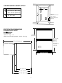
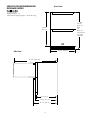
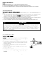
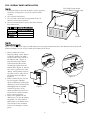
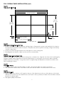
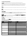
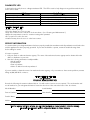
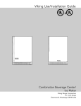
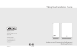
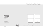
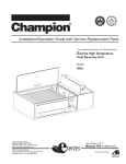
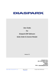
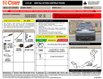
Viking Use/Installation Guide
Refrigerated Drawer
Retain for Future Reference
IMPORTANT - PLEASE READ AND FOLLOW
•
•
•
•
•
Before beginning, please read these instructions completely and carefully.
Do not remove permanently affixed labels, warnings, or plates from the product. This may void the warranty.
Please observe all local and national codes and ordinances.
Please ensure that this product is properly grounded.
The installer should leave these instructions with the consumer who should retain for local inspector’s use and for
future reference.
WARNING
To reduce the risk of fire, electrical shock, or injury when using your refrigerated drawer, follow basic precautions
including the following:
•FOR YOUR SAFETY•
DO NOT STORE OR USE GASOLINE OR OTHER FLAMMABLE VAPORS AND LIQUIDS IN THE VICINITY OF THIS OR
ANY OTHER APPLIANCE. THE FUMES CAN CREATE A FIRE HAZARD OR EXPLOSION.
It is your responsibility to be sure your refrigerated drawer is:
•located so the front is not blocked to restrict incoming or discharge air flow.
•properly leveled.
•located in a well ventilated area.
•connected to the proper kind of outlet, with the correct electric supply and grounding. A 115 volt, 60 Hz, 15 amp
fused electrical supply is required. NOTE: Time delay fuse or circuit breaker is recommended.
•not used by anyone unable to operate it properly.
•used only for its intended purpose.
•properly maintained.
•SAVE THESE INSTRUCTIONS•
PROPER DISPOSAL OF YOUR OLD REFRIGERATION PRODUCT
DANGER
SUFFOCATION HAZARD
Remove doors from your old refrigerated drawer.
Failure to do so can result in child entrapment, which can cause death
or brain damage.
IMPORTANT: Child entrapment and suffocation are not problems of the
past. Junked or abandoned refrigerated drawers are still dangerous, even
if they will sit for “just a few days.” If you are getting rid of your
refrigerated drawer, please follow the instructions below to help prevent
accidents.
BEFORE YOU THROW AWAY YOUR OLD REFRIGERATION PRODUCT:
•Take off the doors.
•Leave the shelves in place so that children may not easily climb inside.
2
UNDERCOUNTER CABINET CUTOUT
A
24” (61.0 cm)*
B
Min. 34 1/2” (87.6 cm)
A
Max. 35 1/8” (89.2 cm)
C
C
B
24” (61.0 cm)
*
*Optional:
Cutout for electrical
outlet can be
placed in adjacent
cabinetry.
SPECIFICATIONS/DIMENSIONS
PROFESSIONAL SERIES
Basic Electric Data
•115 VAC/60 Hz
•Maximum amps - 3.3
•Approximate Shipping Weight - 180 lbs. (81.8 kg)
30 3/4”
(78.1 cm)
Min. 34 1/4”
(87.0 cm)
Max 35”
(88.9 cm)
with leveling
legs fully
extended
47 1/4” (120.0 cm)
23 7/8” (60.6 cm)
22” (55.9 cm)
24 3/8” (61.9 cm)
26 7/8” (68.3 cm)
3
SPECIFICATIONS/DIMENSIONS
DESIGNER SERIES
Front View
Basic Electric Data
•115 VAC/60 Hz
•Maximum amps - 3.3
•Approximate shipping weight - 180 lbs (81.8 kg)
Mín.
34 1/4”
(87.0 cm)
Max.
35”
(88.9 cm)
with leveling
legs fully
extended
30 3/4”
(78.1 cm)
23 7/8” (60.6 cm)
Side View
47 1/4” (120.0 cm)
22” (55.9 cm)
24 3/8” (61.9 cm)
25 3/8” ( 64.5 cm)
4
GENERAL INFORMATION
Unpack
1. Remove banding from bottom of carton. Lift carton up and off of the unit.
2. Remove all tape and packaging material from the outside and inside of the cabinet.
3. Keep all carton packaging until your unit has been thoroughly inspected and found to be in good condition.
AREA REQUIREMENTS
Units Certified for Indoor Use - (black outer cabinet)
MUST BE INSTALLED IN AN AREA PROTECTED FROM THE ELEMENTS, SUCH AS WIND, RAIN, WATER (SPRAY OR
DRIP).
1. Place unit so the front side will be completely unobstructed to provide proper air flow. The unit may be closed in
on the top and three sides, but the front MUST BE unobstructed for air circulation and proper operation.
Installation should be such that the cabinet can be moved for servicing if necessary.
2. Unit should be in a well ventilated area. Best results are obtained at temperatures between 550F (12.80C) and 800F
(270C) for built-in products and 550F (12.80C) and 900F (320C) for freestanding products.
3. Provisions for electricity and water connection should be determined before placing unit in proper place.
WARNING
IMPORTANT!
Disconnect power source before adjusting leveling legs. A cabinet “anti-tip” device is mounted to the back of
your refrigerated drawer. If installation is a built-in undercounter application, you do not need to apply this
feature. If your installation is a free-standing application with no counter top directly above the top of the
refrigerated drawer, you must apply this feature to prevent the unit from tipping forward when the drawers are
pulled out. the “anti-tip” device is attached at the back of each cabinet. Please see installation instructions
supplied with the “anti-tip” device.
LEG LEVELER INSTALLATION
Read Before Installing Leg Levelers
WARNING: Do not lay unit on top, side, back, or front. If unit is accidentally laid
in any position other than right side up, then the unit must remain in the right side
up position for at least 24 hours before plugging the unit in.
1. Tip unit backwards so there is one foot of clearance on front of the unit. Have
someone to assist you in tilting the unit to prevent it from falling on you while
installing the leg levelers.
2. Screw front two (2) leg levelers into the weldnuts. Leg levelers should be
screwed in unit snug.
3. Repeat steps 1 & 2 with the exception of tipping the unit forwards to screw in
the back two leg levelers.
4. The leg levelers are now installed.
5. The unit should be level from front to back and side to side. If floor conditions
do not allow the unit to sit level, adjust the leg leveler by turning the required
leg leveler counter-clockwise to increase the height and clockwise to reduce
the height.
5
Weldnut
(Each bottom
corner of unit)
Leg Leveler
(4) per unit
FULL OVERLAY PANEL INSTALLATION
Step #1
1. A #10 pan head wood screw should be used to properly
secure the overlay panel. A total of 8 screws will be
needed.
2. Use only pan head screws.
3. Do not select a screw that is longer than the wood
thickness of the screw locations.
4. Use recommended pilot holes for the frame material.
(Use chart below.)
5/16 Phillips Head Screws
Holding Drawer Front (8 total)
Pilot Hole Drill Sizes for Wood Screws
Wood Screw Size #10
Work Material
Pilot Hole Size
Hardwood
3/32
Softwood
5/64
Gasket
Step #2
Remove Drawer Fronts
(Note: The overlay panel may be installed without removing the drawer fronts from the drawer bodies, but the full
drawer assembly is not as easy to handle as the drawer front alone.)
1. Remove drawer from unit.
Begin by pulling out the drawer.
Locate the drawer lock which
can be found on the outside of
the cabinet slide. (Figure 1).
Push the back of the drawer
lock forward and then down,
releasing the drawer from the
cabinet slide. (Figure 2). Repeat
this on the opposite side of the
drawer. Lift the drawer up from
the slides at 90o to fully remove
the drawer from the cabinet.
(Figure 3).
2. Remove drawer fronts. Do this
by removing the 8 phillips
screws and washers securing the
drawer front to the drawer body.
Mark lightly with an erasable
marker the position of the
stainless drawer liner where it is
secured to the stainless drawer
before removing screws.
3. Remove the gasket from the
drawer front. Do this by pulling
the gasket our of the channel
that holds it to the drawer front.
This will expose the clearance
holes for mounting the overlay
panel.
Figure 2
Figure 1
Figure 3
6
FULL OVERLAY PANEL INSTALLATION (con’t)
Step #3
Sizing the Overlay Panel
23 5/8” (60.0 cm)
14 5/8”
(37.1 cm)
15 3/16”
(38.6 cm)
7 19/32”
(19.3 cm)
9/16” (1.4 cm)
9/16”
(1.4 cm)
11 13/16” (30.0 cm)
23 1/16” (58.6 cm)
Step #4
Attaching the Overlay Panel to the Door
1. Set the overlay panel on drawer front face and align edges. Clamp panel in position and mark pilot hole locations.
See Step #3 for nominal size and hole locations. Drill pilot holes (remove panel if necessary, re-align and re-clamp
overlay to drawer face.)
2. Insert wood screws through clearance holes and tighten to secure overlay panel.
3. Reinstall gasket into channel. Make sure the corners are inserted fully.
Step #5
Reattach Drawer Front to Drawer Body
Align mounting holes on drawer body with mounting holes on drawer front. Align the door liner to the front flanges by
using the erasable marker alignment lines that were applied prior to removing the door from the drawer. Reinstall
phillips head screws and washers. Snug down, but do not tighten fully, final adjustment of drawer front will be done
after reinstalling the drawer.
Step #6
Reinstall the Drawer
1. Fully extend drawer slides and place drawer on slides. Be sure that drawer sits evenly on both sides.
2. Lock drawers into drawer slides. Push drawer locks down and then back to relock the drawer into the slide.
Step #7
Adjust Drawer Front
1. Adjust drawer front to achieve a 1/8” gap from the top of the drawer front to the top of the cabinet or (for bottom
drawers) 1/8” from the top of the drawer front to the bottom of the top drawer, the drawer front should be centered
between the cabinet edges.
2. Fully tighten phillips head screws
7
ELECTRICAL CONNECTION
WARNING
ELECTRICAL SHOCK HAZARD
Failure to follow these instructions could result in fire or electrical
shock.
Electrical Requirements
Power Supply
A 115 volt, 60 Hz, AC only 15 amp fused electrical supply is required. (A time
with 3-prong
delay fuse or circuit breaker is recommended.) It is recommended that a separate grounding plug
circuit, serving only this appliance, be provided.
Grounding type wall
receptacle
•ELECTRICAL GROUND IS REQUIRED ON THIS APPLIANCE.
•DO NOT UNDER ANY CIRCUMSTANCES REMOVE THE POWER SUPPLY CORD
GROUND PLUG.
•DO NOT USE AN EXTENSION CORD
Recommended Grounding Methods
For your personal safety, this unit must be grounded. This appliance is equipped
with a 7’ (2.1 m) power supply cord having a 3-prong grounding plug. To minimize possible shock hazard, the cord must be
plugged into a mating 3-prong grounding type wall receptacle grounded in accordance with the National Electrical Code and
local codes and ordinances. If the circuit does not have a grounding type receptacle, it is the responsibility and obligation of
the customer to exchange the existing receptacle in accordance with the National Electrical Code and applicable local codes
and ordinances. The third ground plug SHOULD NOT, under any circumstances, be cut or removed. All UL listed refrigerated
drawers are equipped with this type of plug.
FINAL PREPARATION
1. Some stainless steel parts may have a plastic protective wrap which must be peeled off. The interior of the unit should be
washed thoroughly with hot, soapy water, rinsed and wiped dry to remove film residue and any installation dust or debris
before being used. Solutions stronger than soap and water are rarely needed.
2. All stainless steel parts should be wiped with hot soapy water. If buildup occurs, do not use steel wool, abrasive cloths,
cleaners, or powders. If it is necessary to scrape stainless steel to remove encrusted materials, soak with hot, wet cloths to
loosen the material, then use a wood or nylon scraper. Do not use a metal knife, spatula, or any other metal tool to scrape
stainless steel; scratches are almost impossible to remove.
WIRING DIAGRAM
UNDERCOUNTER 24” W. REFRIGERATED DRAWER
WARNING: ELECTRICAL
GROUNDING
INSTRUCTIONS
This appliance is equipped with a
three prong grounding plug for
your protection against shock
hazard and should be plugged
directly into a properly grounded
three prong receptacle. Do not
cut or remove the grounding
prong from this plug.
8
OPERATING INSTRUCTIONS
General Tips and Suggestions
•After making a temperature adjustment, allow at least 24 hours for your unit to reach a new temperature setting.
•The motor will start and stop often. It must do this to maintain the temperature setting.
•Unplug the unit before working on anything with the electrical system.
•Exercise caution when sweeping, vacuuming, or mopping near the front of the unit.
•Avoid leaning on the drawer fronts. You may bend the drawer slides or tip the unit.
Setting the Controls
The temperature of our drawer unit ranges from 32oF to 47oF (0oC to 8oC). The
temperature can be adjusted using the control panel located on the inside of the top
drawer. To change the temperature setting, press the warmer or cooler pads until the
display shows the desired temperature. After a few seconds the display will return to
the actual temperatures. To change from Farenheit to Celsius, simply press the warmer
and colder keypads simultaneously. The display will change within a few seconds.
34oF 01oC
The on/off key pad stops and starts the cooling of the unit. This can be used when
your drawer refrigerator will not be used for extended periods of time. The LED light
will continue to operate when the drawers are opened as long as the unit is connected
to a power source.
At time of initial start up the control panel display will show “OR” for “Out of Range”
until the unit reaches the desired temperature.
OR
INTERIOR LIGHT
WARNING
CAUTION
ELECTRICAL SHOCK HAZARD
Failure to disconnect the power cord when changing
the light bulb may result in electrical shock.
Never pour liquids directly onto light assembly
LED LIGHT REPLACEMENT
1. Unplug unit.
2. Remove drawers. (This is not required to remove the light, but will provide better access). See Figures 1 through 3
in Full Overlay Panel Installation on page 6.
3. Remove old lights. Use 2 small, thin bladed screwdrivers or putty knives to press in the locking tabs on the lens
housing. (Figures 4 and 5). With the locking tabs depressed, pull downward (Figure 6), the light housing will pop
free. Disconnect the wire lead by pulling straight out from the connector. Connect wire lead to new light and reinstall into metal housing. The light will only fit in the housing with the locator tabs pointing to the front of the unit.
4. Re-install drawers.
5. Plug in unit.
Figure 4
Figure 5
Figure 6
9
CLEANING AND MAINTENANCE
Any piece of equipment works better and lasts longer when maintained properly and kept clean.
Condenser
The condenser tubing inside the cabinet does not require frequent cleaning; however, satisfactory cooling depends on
adequate ventilation over the coils. Be sure that nothing obstructs the required air flow openings in front of the cabinet.
Spiders and insects can nest in and around the refrigerated drawer causing damage to the unit. Frequently brush or
vacuum lint and dirt from the condenser coils for efficient performance by unscrewing the grill on the bottom front of
cabinet.
Cabinet
The cabinet can be washed with mild soap and water and thoroughly rinsed with clear water. Never use abrasive scouring
powders.
Interior
Wash interior compartment with mild soap and water. Do not use abrasive powder, solvent, polish cleaner or undiluted
detergent.
Stainless Steel Parts
All stainless steel parts should be wiped regularly with hot soapy water. Use a liquid cleaner designed for stainless steel
when soapy water will not do the job. Do not use steel wool, abrasive cloths, cleansers, or powders. Do not permit citrus
or tomato juice to remain on stainless steel surfaces, as citric acid will permanently discolor stainless steel.
Brass Parts
CAUTION: All brass parts are coated with an epoxy coating. DO NOT USE BRASS OR ABRASIVE CLEANERS ON
THE BRASS PARTS. All brass parts should be wiped regularly with hot soapy water. When hot soapy water will not do
the job, use every day non-abrasive household cleaners.
Door Gasket
The vinyl gasket may be cleaned with mild soap and water, a baking soda and water solution, or a mild scouring powder.
Painted Surfaces
Wash with warm soapy water. DO NOT USE steel wool, abrasive cleansers, ammonia, acids or commercial oven cleaners
which may damage the finish.
TROUBLESHOOTING CHART
Problem
Possible Cause
Odor in cabinet
Noisy operation
Unit vibrates.
•Unit interior needs cleaning.
•Unit not level.
•Unit not level.
•Weak floor.
Interior lighting not working.
•LED light burned out.
•No power at outlet.
Appliance will not run.
•Control panel turned “OFF”.
•Power cord not plugged into power
source
•House fuse blown.
Appliance runs too long.
•Prolonged door openings.
•Control panel set too cold.
•Condenser needs cleaning.
Moisture collects inside of unit. •Too many door openings
•Prolonged door openings.
•Hot, humid weather increases
condensation.
Moisture collects on outside
•Hot, humid weather increases
surface of the unit.
•Control improperly set.
Interior too hot/too cold
•Control improperly set.
•Faulty thermometer.
10
Solution
•Clean inside of unit. See p. 10.
•Adjust leveling legs. See p. 5.
•Adjust leveling legs. See p. 5.
•Rebuild floor or move to a different location.
•Replace LED light.
•Test outlet with lamp.
•Turn unit on with on/off pad on control panel.
•Plug unit into power source
•Reset house fuse.
•Reduce number and/or duration of openings.
•Raise temperature of unit via control panel.
•Clean condenser. See p. 10.
•Reduce number of door openings.
•Reduce duration of door openings.
•Move unit to cooler location.
•As humidity decreases, moisture will disappear.
•Move unit to a cooler location.
•Reset to slightly warmer temperature.
•Reset control to desired temperature.
•Recheck with second thermometer.
DIAGNOSTIC LED
In the back in the grille, there is a diagnostic/status LED. This LED is used to help diagnosis any problem with the unit
and to tell its status.
LED Status
Code/Problem
Not on or blinking
Continuously on
1 blink and pause
2 blinks and pause
3 blinks and pause
Unit does not have power
Unit is “ON” and operating correctly
For shorted or open thermistor
Disconnected display board
Compressor is locked out
ENERGY SAVING TIPS
•Reduce drawer openings.
•Close the drawer as soon as you can.
•Keep the condenser coils on bottom of the unit clean. (See “Cleaning and Maintenance”.)
•Adjust the temperature control to a warmer setting when practical.
•Do not put hot foods in the unit.
•Install unit away from the stove or other heat sources.
SERVICE INFORMATION
It is assumed that your refrigerated drawer has been properly installed in accordance with all specifications and local codes
and the appliance has been properly grounded. If your unit should fail to operate, review the troubleshooting chart
before calling for service.
If service is required:
1. Call your dealer or authorized service agency. The name of the authorized service agency can be obtained from the
dealer or distributor in your area.
2. Have the following information readily available:
•Model number
•Serial number
•Date of purchase
•Name of dealer from whom purchased
If you are unable to obtain the name of an authorized service agency, or if you continue to have service problems, contact
Viking at (888) 845-4641 or write to:
VIKING PREFERRED SERVICE
111 Front Street
Greenwood, Mississippi 38930 USA
Record the following information indicated below. You will need it if service is ever required. The serial number and
model number for your refrigerated drawer is located on the front of the unit at the base of the door frame.
Model Number
Serial Number
Date of Purchase
Date Installed
Dealer’s Name
Address
If service requires installation of parts, use only authorized parts to ensure protection under the warranty.
This manual should remain with the refrigerated drawer for future reference.
11
UNDERCOUNTER/FREESTANDING REFRIGERATED DRAWER WARRANTY
(Units certified for Indoor Use)
TWO YEAR FULL WARRANTY
Undercounter/freestanding refrigerated drawers and all of their components and accessories, except as detailed below*, are warranted to be free from defects in material or
workmanship under normal household use for a period of two (2) years from the date of original retail purchase. Viking Range Corporation, warrantor, agrees to repair or
replace, at its option, any part which fails or is found to be defective during the warranty period
*Painted and decorative items are warranted to be free from defective materials or workmanship for a period of ninety (90) days from the date of original retail purchase.
ANY DEFECTS MUST BE REPORTED TO THE SELLING DEALER WITHIN NINETY (90) DAYS FROM DATE OF ORIGINAL RETAIL PURCHASE.
SIX YEAR FULL WARRANTY
Any sealed refrigeration system component, as listed below, is warranted to be free from defective materials or workmanship in normal household use during the third
through the sixth year from the date of original retail purchase. Viking Range Corporation, warrantor, agrees to repair or replace, at its option, any part which fails or is found
to be defective during the warranty period.
Sealed Refrigeration System Components:
Compressor, Evaporator, Condenser, Connecting Tubing, Dryer/Strainer
TWELVE YEAR LIMITED WARRANTY
Any sealed refrigeration system component, as listed above, which fails due to defective materials or workmanship in normal household use during the seventh through the
twelfth year from the date of original retail purchase will be repaired or replaced, free of charge for the part itself, with the owner paying all other costs, including labor.
NINETY (90) DAY RESIDENTIAL PLUS WARRANTY This warranty applies to applications where use of the product extends beyond normal residential use.
Examples are, but not limited to, bed and breakfasts, fire stations, private clubs, churches, etc. This warranty excludes all commercial locations such as restaurants,
food service locations and institutional food service locations.
This warranty extends to the original purchaser of the product warranted hereunder and to each transferee owner of the product during the term of the warranty.
This warranty shall apply to products purchased and located in the United States and Canada. Products must be purchased in the country where service is requested.
Warranty labor shall be performed by an authorized Viking Range Corporation service agency or representative. Warranty shall not apply to damage resulting from abuse,
accident, natural disaster, loss of electrical power to the product for any reason, alteration, improper installation, improper operation or repair or service to the product by
anyone other than an authorized Viking Range Corporation service agency or representative. Warranty shall not apply to damage resulting from indoor units being used in
outdoor situations. This warranty does not apply to commercial usage. Warrantor is not responsible for consequential or incidental damage whether arising out of breach of
warranty, breach of contract, or otherwise. Some jurisdictions do not allow the exclusion or limitation of incidental or consequential damages, so the above limitation or
exclusion may not apply to you.
Owner shall be responsible for proper installation, providing normal care and maintenance, providing proof of purchase upon request, and making the appliance reasonably
accessible for service. If the product or one of its component parts contains a defect or malfunction during the warranty period, after a reasonable number of attempts by
the warrantor to remedy the defects or malfunctions, the owner is entitled to either a refund or replacement of the product or its component part or parts. Replacement of a
component part includes its free installation. Warrantor’s liability on any claim of any kind, with respect to the goods or services covered hereunder, shall in no case exceed
the price of the goods or service or part there of which gives rise to the claim.
WARRANTY SERVICE: Under the terms of this warranty, service must be performed by a factory authorized Viking Range Corporation service agent or representative.
Service will be provided during normal business hours, and labor performed at overtime or premium rates shall not be covered by this warranty. To obtain warranty service,
contact the dealer from whom the product was purchased, an authorized Viking Range Corporation service agent, or Viking Range Corporation. Provide model and serial
number and date of original purchase. For the name of your nearest authorized Viking Range Corporation service agency, call the dealer from whom the product was
purchased or Viking Range Corporation. IMPORTANT: Retain proof of original purchase to establish warranty period.
The return of the Owner Registration Card is not a condition of warranty coverage. You, however, should return the Owner Registration Card so that Viking Range
Corporation can contact you should any question of safety arise which could affect you.
Any implied warranties of merchantability and fitness applicable to the above described undercounter refrigerated drawer are limited in duration to the period of coverage of
the applicable express written limited warranties set forth above. Some jurisdictions do not allow limitations on how long an implied warranty lasts, so the above limitation
may not apply to you. This warranty gives you specific rights, and you may also have other rights which may vary from jurisdiction to jurisdiction.
Specifications subject to change without notice
Viking Range Corporation
111 Front Street
Greenwood, Mississippi 38930 USA
(662) 455-1200
For product information
call 1-888-VIKNG1 (845-4641)
or visit the Viking Web Site at
vikingrange.com
F20411B
41009286 Rev. A
(062007J)