1
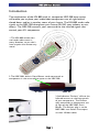
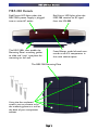
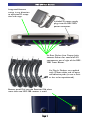
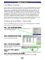
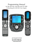
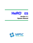
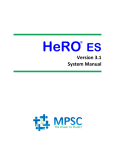
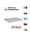
MRF-200
INSTALLATION
MANUAL
Multi-Room “No-Pointing” RF Control of
Audio/Video Components
MRF-200 Installation Manual © 2003 Universal Remote Control, Inc.
The information in this manual is copyright protected. No part of this manual may be copied
or reproduced in any form without prior written consent from Universal Remote Control, Inc.
UNIVERSAL REMOTE CONTROL, INC. SHALL NOT BE LIABLE FOR OPERATIONAL,TECHNICAL OR EDITORIAL ERRORS/OMISSIONS MADE IN THIS MANUAL.
The information in this manual may be subject to change without prior notice.
Home Theater Master is a registered trademark of Universal Remote Control, Inc.
Entertainment Made Simple is a trademark of Universal Remote Control, Inc.
All other brand or product names are trademarks or registered trademarks of their respective
companies or organizations.
500 Mamaroneck Avenue, Harrison, NY 10528
Phone: (914) 835-4484 Fax: (914) 835-4532
TABLE OF CONTENTS
Introduction
1
Features and Benefits
2
Parts Guide
2
Front Panel
3
Mounting Plate
3
Power LED
3
Status LED
3
Front Blaster
3
Rear Panel
4
Flashers
4
Power Supply
4
Bottom Panel
4
Receiver ID#
4
A Standard MRF-200 System
5
Standard Installation — Step by Step
5
Front Blaster Overload
7
Disabling the Front Blaster - Step by Step
7
Controlling An Array of Identical TV’s
8
Identical Components - Step by Step
8
Programming For Multiple Equipment Locations
11
Frequently Asked Questions
12
Specifications
12
MRF-200 BASE STATION
Introduction
The combination of the MX-800 with it’s companion MRF-200 base station
will enable you to place your audio/video components out of sight behind
closed doors and/or in another room of your house. The MX-800 sends radio
signals to the MRF-200 throughout your house (50-100’ away, indoors or outdoors). The MRF-200 converts your commands to the infrared signals that
control your A/V components.
1.The MX-800 remote control sends radio waves in
every direction, so you don’t
have to point the remote anymore!
2.The MRF-200’s built-in Front Blaster sends commands to
components in the same cabinet space as the MRF-200.
3. Self-adhesive “Flashers” affix to the
Infrared sensors on the front panels
of your components. The Flashers
relay commands to components out
of sight of the MRF-200’s Front
Blaster. The flashers plug in to the
MRF-200’s rear flasher line outputs
via their 10 foot cables.
Page 1
MRF-200 BASE STATION
Features and Benefits
No More Pointing - Radio Waves Penetrate Walls, Doors and Floors
The MRF-200 receives the RF signals of the MX-800 remote control from any
direction. You no longer need to point the remote control at any of your A/V
components. You can also place the components distracting blinking lights and
displays behind closed doors and/or in another room!
Reliable Control Throughout Your House
The MRF-200 receives RF signals from your MX-800 from within a radius of
50 to 100 feet enabling you to control out of sight audio/video components
behind walls and closed doors. Range depends on the structure of your home
and the amount of interference generated by computers, microprocessors and
other devices within and nearby your home.
Up To Sixteen Equipment Locations Controlled From Any MX-800
Each MX-800 can be programmed to operate equipment placed throughout
the house, by installing an MRF-200 base station at each location. Each MRF200 is assigned one of 16 unique ID#’s. In operation it’s simple: when you
select a device located in the Den, the MX-800 only talks to the MRF-200 in
the Den. When you select a device located in the Family Room, the MX-800
only talks to it!
No Pointing Remote Controls In Every Room
You can opt to control a multi-room or multi-zone system via RF remote control by placing an MX-800 in each room of your home.
Control A Media Room Array of Identical TV’s
The MRF-200’s unique assignable IR flashers enable your installation to control
up to six identical TV’s. The intelligent routing of the MRF-200 will send your
commands only to the TV you select on your MX-800. The other identical
TV’s will not receive commands. Of course, if your system utilizes identical
satellite receivers, cable boxes, VCR’s or disc changers you can utilize IR routing just as easily for them. If you have more than six identical components, up
to 16 additional MRF-200’s can be installed to control them (thus allowing up
to 96 identical components in one house).
Parts Guide
The MRF-200 RF Base Station includes:
1 - MRF-200 Receiver with integrated antenna
1 - Mounting Plate for wall mounting the MRF-200
4 - Screws for wall mounting the mounting plate
1 - 9V-300mA Power Supply
6 - Flashers with 10 foot plug in cables.
Page 2
MRF-200 BASE STATION
MRF-200 Details
Red POWER LED lights when the
MRF-200’s power supply is plugged
into an active AC outlet.
Red STATUS LED lights when the
MRF-200 receives an RF signal
from the MX-800.
The MRF-200’s slots enable the
Mounting Plate’s matching guides
to slide and “snap” into place for
mounting on the wall.
Front Blaster sends Infrared commands to all A/V components in
the same cabinet space.
The MRF-200 Mounting Plate
Using the four enclosed
screws, you can choose to fix
the mounting plate to a wall or
the back of your component
cabinet.
Page 3
MRF-200 BASE STATION
Integrated Antenna
swings in any direction
to optimize RF reception and range.
Included 9V power supply
plugs into the MRF-200’s
power connector.
Six Rear Flasher Line Output Jacks
connect flashers for control of A/V
components out of sight of the MRF200’s Front Blaster.
Six Plug-In Flashers are supplied
with 10 foot cables and six extra
self-adhesive pads (in case a flasher has to be repositioned).
Bottom panel Dial sets the Receiver ID# when
more than one MRF-200 receiver is used.
Page 4
MRF-200 BASE STATION
A Standard MRF-200 System
A standard system utilizes no identical components and only one equipment
location. However, you can add any number of MX-800 remote controls to
your home! MX-800’s are available as an accessory purchase without an MRF200 for standard system installations that already have an MRF-200.
You can add any number of MRF-200 base stations in a standard system as
well. If you need more than six flasher outputs you may add additional MRF200 receivers as needed by ordering an accessory MRF-200 base station.
Do not change the factory default settings in RF Control section of MXEditor
when you download to your MX-800’s. You do not need to utilize MXEditor’s
Program Step 9 (RF Control), since the factory settings will work fine!
Standard Installation — Step by Step
Step 1 - Program and Download to the MX-800
Connect your MX-800 to your PC and program the IR commands and macros as
you like. Since your MX-800 sends both IR and RF, you can test your programming as you go by pointing the MX-800 at the components and using MXEditor’s
TEST and Macro Play features if you place your laptop PC in the same room as
the components (with the cabinet doors open and in line of sight).
For a detailed explanation of how to program, use the downloadable
Programming Manual or the animated Tutorial. Both are available as free downloads from the www.hometheatermaster.com website.
Important Note: Do NOT power up the MRF-200 at this point. You need to
test your IR commands and Macros line of sight via IR only at this point!
Once you have completed and downloaded your programming to the MX-800
remote control, you are ready to test RF operation via the Front Blaster and
(if necessary) the self-adhesive flashers that connect to the MRF-200’s flasher
line outputs.
Step 2 - Place the MRF-200
The MRF-200 should be placed so that the Front Blaster will control as many
of the system’s A/V components as possible. If you are connecting the outboard flashers to the rear Flasher outputs only, the MRF-200 may be concealed and mounted to the rear wall or back of the system cabinet.The
mounting plate slides apart from the receiver, screws to the wall or cabinet
Page 5
MRF-200 BASE STATION
with the enclosed screws, then the receiver is slid back into place.
Step 3 - Connect the Power Supply and Insert the Batteries
Connect the 9V power supply to an active UNSWITCHED AC outlet. The MRF200 must always be powered up to operate.The red POWER LED should light.
Insert the batteries in the MX-800 remote control.
Step 4 - Test the MX-800
Observe the MRF-200’s STATUS LED blinking while you press and hold a programmed button (one with an actual command).This tells you that the MRF200 is receiving the RF commands of the MX-800.
Step 5 - Orient the Antenna for Optimum Range
If you need to extend the range of the remote, try adjusting the angle of the
MRF-200 receiving antenna via it’s pivoting ball mount.
Step 6 - Test Operation Without Flashers
With the MX-800’s IR output blocked by a jacket or pillow, test the control of
your components using just the Front Blaster. In most cabinets, the MRF-200’s
Front Blaster will control any A/V components in the same cabinet space by
reflections from the cabinet walls and doors. Make sure that the components
operate with the cabinet doors closed or open. If a component is placed too far
away from the front blaster, you will need to utilize the included Flashers plugged
into the MRF-200’s rear Flasher Line Output jacks.
If you have problems with components that are close to the Front Blaster, see
the next page and the section on Front Blaster Overload.
Step 7 - Connect Flashers to Out of Sight A/V Components
Important Note: Test the operation BEFORE sticking the flasher in place.
Use a flashlight to identify the correct location of the component’s IR sensor,
then try a few commands while moving the flasher around the face plate of
the component. The most reliable operation typically occurs a half inch or so
away from the IR sensor.
Once you have found the spot that gives the most reliable operation, peel off
the protective backing of the self-adhesive tape on the included Flashers and
stick them in place.
Important Note: Always replace the self-adhesive tabs if you have to reposi tion a flasher. Six extra self-adhesive tabs are supplied for this purpose.
Page 6
MRF-200 BASE STATION
Front Blaster Overload
A few models of audio/video components can be OVERLOADED by the Front
Blaster. If you are having intermittent or inconsistent results with a particular
component, try repositioning the MRF-200 and facing the Front Blaster in a
different direction. If this improves the situation but is impractical, it may be
necessary to utilize the self-adhesive flashers only and follow the steps below
to Disable the Front Blaster. This will limit the number of components your
MRF-200 can control to six. If you have more than six components you can
purchase an additional MRF-200 (available as an accessory alone from your
Home Theater Master dealer). Do not change the receiver ID# (use the same
ID # as the first unit) then follow the steps on the following pages:
Disabling the Front Blaster - Step by Step
Plug the MX-800 back into the PC. Open your saved configuration and follow
these steps to turn off the front blaster:
Step 1 - Open the RF Setup Window
The RF Setup window opens after selecting RF Control
from the Program Menu.
Step 2 - Reveal the Receiver settings
Extend the RF Setup window by clicking on the Receivers button.
Step 3 - Turn off the Front Blaster
Click on the cell in the IR Blaster
column. A list box will appear. Select
OFF from the list.
Next, click on OK to apply your
change.
Step 4 - Save and Download to the MX-800
SAVE your changes using File|Save and DOWNLOAD to the MX-800.
Page 7
MRF-200 BASE STATION
Controlling An Array of Identical TV’s
(or VCR’s, Receivers, CD players etc.)
There are several considerations to take into account when you are installing
an MRF-200 to control an array of identical components:
1. You cannot use the Front Blaster to control identical components. You
must use Flashers instead. You can still use the Front Blaster in a cabinet
that is out of sight of the identical components to control the rest of your
system.
2. Each identical component must receive IR commands ONLY from a dedicated Flasher affixed to it’s front panel. The IR output of the MX-800 should be
disabled for each identical component. It can still be utilized for the rest of
your system!
3. You must note the NUMBER of the Flasher Output you have utilized for
EACH of the identical components.
NOTE: If the identical components are near each other the Flashers and the
actual sensor window of the component should be blocked with black
electrical tape (sometimes more than one layer is needed).
Identical Components - Step by Step
Step 1 - Create a Device for Each TV in MXEditor
The MX-800 can control up to 20 devices. You must create one device for
each of your identical TV’s.
In this example, six identical TV’s are utilized in a
Media Room array.
The programmer has
created devices for all of
the equipment in the
cabinet on Main Page 1.
On Main Page 2, he/she
has created a device for
each of the TV’s.
Step 2 - Program One Device With IR commands.
Using either the IR Database or Learning, program one of the identical devices
to operate one of TV’s (leave the others powered off right now).Test all commands and Save your work.
Page 8
MRF-200 BASE STATION
Step 3 - Copy The Programmed Device
In tree view, right click on the device you programmed.
From the context menu that appears, select COPY.
Step 4 - Paste The Programmed Device
In tree view, right click on the first device that is NOT
PROGRAMMED. From the context menu that appears,
select PASTE.
Repeat this PASTE on all of the other identical device.
Save your work.
Step 5 - Open the RF Setup Window
The RF Setup window opens after selecting RF
Control from the Program Menu.
The RF Setup window is composed of a “spread sheet” of options for EACH
of your devices. By looking at the Signal column, you can see that the factory
default programming sets all of the devices to send both IR and RF commands.
If you look at the column for Flashers, you can see that the default sends IR
commands for all devices to ALL of the flashers. Both options must be
changed for identical components. Additionally, if you are not using it, you may
wish to disable the Front Blaster (see page 7 for directions).
Step 6 - Adjust the Signal For Each of the Identical Devices
The RF Setup window enables you to adjust the Signal output by the MX-800
for each device individually, by clicking on the intersection of a row and a column and then selecting RF from the three options shown in the pull down list
box .
Page 9
MRF-200 BASE STATION
Click on the “cell” for the first
identical TV, by crossing the
device row with the Signals column.
Signal Column
TV1 Device Row
Select RF from the three options shown for EACH of the identical TV’s. You
may leave the other components of the system set to IR & RF.
Step 7 - Adjust the Flashers For Each of the Identical Devices
The RF Setup window enables you to adjust which Flashers output by the MX800 for each device individually, by clicking on the intersection of a row and a
column and then selecting 1-6 from the seven options shown in the pull
down list box.
Flasher Column
Click on the “cell” for the first
identical TV, by crossing the
device row with the Flashers
column.
TV1 Device Row
Select the correct Flasher (refer to your connection notes) for EACH of the
identical TV’s. You may leave the other components of the system set to ALL.
Step 8 - Apply, Save, Download and Test
First click on the OK button of the RF Setup window. Next, Save your work.
Finally, download to your MX-800. When you select TV1 with your MX-800,
commands are only sent to it. Likewise for the rest of your identical TV’s!
Page 10
MRF-200 BASE STATION
Programming For Multiple Equipment Locations
You can operate up to 16 different equipment locations, each with an MRF200 assigned a unique Receiver ID#. You program each of your MX-800’s to
talk to the equipment locations you want by assigning each of your devices to
a receiver. First, you must add and name your receivers for the locations they
are placed in:
Step 1 - Open the RF Setup Window
The RF Setup window opens after selecting RF Control from the Program
Menu.
Step 2 - Reveal the Receiver settings
Extend the RF Setup window by clicking on the
Receivers button of the RF setup window.
Step 3 - Add, Name and Assign Receiver ID#
Using the controls at the bottom extended portion of the RF Control window, add new receivers and rename them for the
Add new receivers
by clicking on the
Add button.
Delete receivers by
selecting them first
by clicking on their
Name, then clicking
the Delete button.
Assign the correct Receiver
ID# for each LOCATION by
clicking on the desired CELL
and selecting the ID# you
want from the pull down list.
Each LOCATION should have
a unique ID#. It is ok to
install multiple MRF-200’s in
one location.
You may rename the
Default receiver to
something more
descriptive by clicking
on the Rename button.
Step 4 - Save and Download to your MX-800’s.
Page 11
MRF-200 BASE STATION
Frequently Asked Questions
Can I use flasher/emitters that I have already installed in the system to con nect to the MRF-200?
Yes, the flashers are compatible, however flashers from other companies are equipped
with a mini plug that is too large to fit the MRF-200’s flasher jacks. Use Radio Shack
part # 274-327 to convert 3.5mm plug Flasher/Emitters to the MRF-200.
I have a row of identical TV’s. I’ve correctly set the flasher outputs using MX
Editor, yet when I send a command to one of them, the TV next to the
selected TV also responds. How do I stop this?
Use an opaque material like electrical tape to cover the flasher and the front panel sensor of each of the TV’s. Sometimes several layers are necessary.
How can I increase the range of the MX-800?
Often, you can increase range by repositioning the MRF-200 and/or by re-orienting the
antenna. Try to avoid placing the MRF-200 directly adjacent to satellite
receivers, personal computers or any other component using high speed
microprocessors if possible.
Warranty
The MRF-200 is covered against any manufacturers defects or workmanship
for a period of one year from the date of purchase if purchased from an
authorized Home Theater Master dealer. Units purchased from online auction
sites or other unauthorized resellers have no warranty.This warranty does not
cover the following items:
-Damage from misuse, neglect, or acts of nature.
-Products that have been modified or incorporated into other products.
-Products purchased more than 12 months ago.
-Units purchased from unauthorized dealers or companies.
Specifications
MRF-200
Power Supply: 9V 300mA
IR Flasher Line Outputs: 2.5mm Mono Mini Jack
RF Frequency: 418MHz
Size: 5 1/8” x 3.5” x 1.25” (4.5” antenna up)
MX-800
Range: 50 to 100 feet, depending upon the structure of the house and the
amount of interference present from computers, microprocessors etc.
Weight: 8 oz. (with batteries)
Size: 9.0” x 3.0” x 1.3”
Batteries: Four AAA Alkaline batteries included
LCD Size: 1.4” x 2.1”
Page 12
500 Mamaroneck Avenue, Harrison, NY 10528
Phone: (914) 835-4484 Fax: (914) 835-4532