1
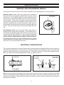
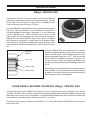
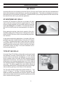
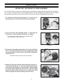
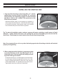
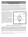
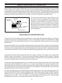
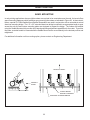
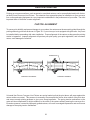
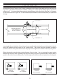
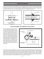
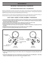
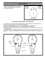
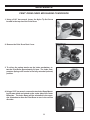
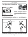
STENCILING & MARKING
SYSTEMS
OWNER’S MANUAL
NON-POROUS
CONVEYOR LINE PRINTERS
ALL MODELS
INSTALLATION - OPERATION - MAINTENANCE
UNIVERSAL STENCILING & MARKING SYSTEMS, INC.
P.O. BOX 871 - ST. PETERSBURG, FLORIDA 33731 USA
PH: (727) 894-3027 FAX: (727) 821-7944
E-Mail: [email protected] Website: www.universal-marking.com
NPCLP-07002
1
IMPORTANT NOTE
UNIVERSAL products are manufactured to exacting standards and every available step has been taken to assure your
complete satisfaction. It is most important, however, that the instructions contained in this manual are read and carefully
followed for best results. Failure to do so may result in unsatisfactory performance, damage to the equipment and personal
injury.
PREFACE
3
○
○
○
○
○
○
○
○
○
○
○
○
○
○
○
○
○
○
○
○
SPECIFICATIONS
CLP-100 Series
CLP-200 Series
Indexing and Non-Indexing Models
Mounting Configurations
Printing Dies
Ink Rolls
○
○
○
○
○
○
○
○
○
○
○
○
○
○
○
○
○
○
○
○
○
○
○
○
○
○
○
○
○
○
○
○
○
○
○
○
○
○
○
○
○
○
○
○
○
○
○
○
○
○
○
○
○
○
○
○
○
○
○
○
○
○
○
○
○
○
○
○
○
○
○
○
○
○
○
○
○
○
○
○
○
○
○
○
○
○
○
○
○
○
○
○
○
○
○
○
○
○
○
○
○
○
○
○
○
○
○
○
○
○
○
○
○
○
○
○
○
○
○
○
○
○
○
○
○
○
○
○
○
○
○
○
○
○
○
○
○
○
○
○
○
○
○
○
○
○
○
○
○
○
○
○
○
○
○
○
○
○
○
○
○
○
○
○
○
○
○
○
○
○
○
○
○
○
○
○
○
○
○
○
○
○
○
○
BASIC PRINCIPLES OF OPERATION
Inking System
Using the 4 Oz. Reservoir Ink Cartridges
Selecting an Appropriate Ink
Ink Drying Time Considerations
○
○
○
○
○
○
○
○
○
○
○
○
○
○
○
○
○
○
○
○
○
○
○
○
WEB PRINTING
Mounting the Coder
Special Web Printing Applications
Printing on Narrow Web Materials
Printing directly on Master Rolls
Gang Mounting
○
○
○
○
○
○
○
○
○
○
○
○
○
○
○
○
○
○
○
○
○
○
○
○
○
○
○
○
○
○
○
○
○
○
○
○
MAINTENANCE
Pre-Inking a New Ink roll
Cleaning the Transfer Roll
Cleaning the Coder
Cleaning the Printing Dies
Mounting Configuration Conversion
Inking System Assembly
○
○
○
○
○
○
○
○
○
○
○
○
○
○
○
○
○
○
○
○
○
○
○
○
○
○
○
○
○
○
○
○
○
○
○
○
○
○
○
○
○
○
○
○
○
○
○
○
○
○
○
○
○
○
○
○
○
○
○
○
○
○
○
○
○
○
○
○
○
○
○
○
○
○
○
○
○
○
○
○
○
○
○
○
○
○
○
○
○
○
○
○
○
○
○
○
○
○
○
○
○
○
○
○
○
○
○
○
○
○
○
○
○
○
○
○
○
○
○
○
○
○
○
○
○
○
○
○
○
○
○
○
○
○
○
○
○
○
○
○
○
○
○
○
○
○
○
○
○
○
○
○
○
○
○
○
○
○
○
○
○
○
○
○
○
○
○
○
○
○
○
○
○
○
○
○
○
○
○
○
○
○
○
○
○
○
○
○
○
○
○
○
○
○
○
○
○
○
○
○
○
○
○
○
○
○
○
○
○
○
○
○
○
○
○
○
○
○
○
○
○
○
○
○
○
○
○
○
○
○
○
○
○
○
○
○
○
○
○
○
○
○
○
○
○
○
○
○
○
○
○
○
○
○
○
○
○
○
○
○
○
○
○
○
○
○
○
○
○
○
○
○
○
○
○
○
○
○
○
○
○
○
○
○
○
○
○
○
○
○
○
○
○
○
○
○
○
○
○
○
○
○
○
○
○
○
○
○
○
○
○
○
○
○
○
○
○
○
○
○
○
○
○
○
○
○
○
○
○
○
○
○
○
○
○
○
○
○
○
○
○
○
○
○
○
○
○
○
○
○
○
○
○
○
○
○
○
○
○
○
○
○
○
○
○
○
○
○
○
○
○
○
○
○
○
○
○
○
○
○
○
○
○
○
○
○
○
○
○
○
○
○
○
○
○
○
○
○
○
○
○
○
○
○
○
○
○
○
○
○
○
○
○
○
○
○
○
○
○
○
○
○
○
○
○
○
○
○
○
○
○
○
○
○
○
○
○
○
○
○
○
○
○
○
○
○
○
○
○
○
○
○
○
○
○
○
○
○
○
○
○
○
○
○
○
○
○
○
○
○
○
○
○
○
○
○
○
○
○
○
○
○
○
○
○
○
○
○
○
○
○
○
○
○
○
○
○
○
○
○
○
○
○
○
○
○
○
○
○
○
○
○
○
○
○
○
○
○
○
○
○
○
○
○
○
○
○
○
○
○
○
○
○
○
○
○
○
○
○
○
○
○
○
○
○
○
○
○
○
○
○
4
5
6
6
7
8
9
10
14
15
○
○
○
○
○
○
○
○
○
○
○
○
○
○
○
○
○
○
○
○
○
○
○
○
○
○
○
○
○
○
○
○
○
○
○
○
○
○
○
○
○
○
○
○
○
○
○
○
○
○
○
○
○
○
○
○
○
○
○
○
○
○
○
○
○
PARTS DIAGRAMS & PARTS LISTS
○
○
○
○
○
○
○
○
○
○
○
○
○
○
○
○
○
○
○
○
○
○
○
○
○
○
○
○
○
○
○
○
○
○
○
○
○
○
○
○
○
○
○
○
○
○
○
○
○
○
○
○
○
○
○
○
○
○
○
○
○
○
○
○
○
○
○
○
○
○
○
○
○
○
○
○
○
○
○
○
○
○
○
○
○
○
○
○
○
○
○
○
○
○
○
○
○
○
○
○
○
○
○
○
○
○
○
○
○
○
○
○
○
○
○
○
○
○
○
○
○
○
○
○
○
○
○
○
○
○
○
○
○
○
○
○
○
○
○
○
○
○
○
○
○
○
○
○
○
○
○
○
○
○
○
○
○
○
○
○
○
○
○
○
○
○
○
○
○
○
○
○
○
○
○
○
○
○
○
○
○
○
○
○
○
○
○
○
○
○
○
○
○
○
○
○
○
○
○
○
○
○
○
○
○
○
○
○
○
○
○
○
○
○
○
○
○
○
○
○
○
○
○
○
○
○
○
○
○
○
○
○
○
○
○
○
○
○
○
CARTON PRINTING
Carton Alignment
Die Positioning for Indexing Applications
○
○
○
○
○
○
○
○
○
○
○
○
○
○
○
○
○
○
○
○
○
○
○
○
○
○
○
○
○
○
○
○
○
○
○
○
○
○
○
○
○
○
○
○
○
○
○
○
○
○
○
○
○
○
○
○
○
○
○
○
○
○
○
○
○
○
○
○
○
○
○
○
○
○
○
○
○
○
○
○
○
○
○
○
○
○
○
○
○
○
○
○
○
○
○
○
○
○
○
○
○
○
○
○
○
○
○
○
○
○
○
○
○
○
○
○
○
○
○
○
○
○
○
QUICK START
Installing the Inking System Assembly
Installing the Pre-Inked Roll
Installing the Printing Dies
Adjusting the Ink Roll Eccentric
○
○
○
○
○
○
○
○
○
○
○
○
○
○
○
16
16
17
18
20
21
21
21
22
23
25
27
28
28
29
30
37
39
- LIMITED WARRANTY UNIVERSAL Non-Porous Conveyor Line Printers are guaranteed to be free from defects in materials and workmanship
for a period of 90 days from the date of purchase. Components found to be defective during this time will be repaired
free of charge if returned to the factory. Damage resulting from use of improper inks, improper installation, or operation
is not covered under the scope of this warranty. For warranty service please contact our Customer Service Department.
2
PREFACE
Printing on non-porous materials has always been a major problem in industrial applications. The high degree of
maintenance required to keep conventional coders operating with solvent based inks has made many companies opt for manual marking as a cost effective alternative. With UNIVERSAL Non-Porous Coders, printing on
non-porous materials can be accomplished with the same relative ease as printing on porous materials. This
breakthrough in Non-Porous coder design opens up in-plant printing opportunities which previously were regarded as too costly to consider.
Inks used to print on porous materials dry through absorption into the material being printed. Inks used to print on
non-porous materials dry through the rapid evaporation of the ink solvents after the print is applied. Since the ink
solvents must evaporate very rapidly on the printed material, they also evaporate very rapidly from the ink rolls
and ink wells of conventional coders therefore requiring constant maintenance.
The proprietary design of the UNIVERSAL Non-Porous Inking System effectively eliminates the rapid evaporation
of the ink solvents from the ink roll and additionally provides for convenient automatic re-inking of the roll without
interrupting the printing process. After many months of design engineering and field testing, the Non-porous
Conveyor Line Printer is both simplistic in design and extremely effective in operation. The relatively low cost of
this system makes in-plant printing of all types of non-porous materials a practical reality. The following pages of
this manual explain the installation, operation and maintenance of Non-Porous Conveyor Line Printer and are the
key to trouble free non-porous printing.
QUICK START
PAGES 9 THRU 15
This manual was written with a full understanding that very few people like to read manuals or have the
time to do so. To accommodate those who have little time to spare, we have included a Quick Start section
which will get your coder operating in just a few minutes.
To keep your coder operating properly, it is important to read and understand the Basic Principles of Operation section which explains the basic operation of the Non-Porous Inking System.
CODER SPECIFICATIONS
The specification section includes drawings with the basic dimensions of the coders, the net weights, maximum
die capacities, maximum print width and print drum circumferences. This section also lists the specifications for
the printing dies and an explanation of the Indexing and Non-Indexing models and the various mounting configurations.
3
SPECIFICATIONS
CONVEYOR LINE PRINTER SPECIFICATIONS
TOP MOUNT SERIES
Model Shown: CLP-100NI-NPRT
8.25
(209.55 MM)
1.56
3.90
(39.62 MM)
4.93
(99.06 MM)
(125.22 MM)
1.13
(28.70 MM)
5.75
11.89
1
2
(302.01 MM)
N
MI
3
X
MA
(146.05 MM)
10.51
(266.95 MM)
11.50
(292.10 MM)
NET WEIGHT:
MAXIMUM DIE SIZE:
MAXIMUM PRINT WIDTH:
PRINT DRUM CIRCUMFERENCE:
10 LBS. - 12 OZS. (4.88 KG.)
7 RIBS WIDE X 16-15/16" LENGTH (7 RIBS WIDE X 430 MM LENGTH)
1" (25.4 MM)
APPROXIMATELY 18" (457 MM) MEASURED AT THE DIE FACE
4
SPECIFICATIONS
CONVEYOR LINE PRINTER SPECIFICATIONS
SIDE MOUNT SERIES
3
2
MI
N
1
MA
X
Model Shown: CLP-200NI-NPLS
5.75
(146.05 MM)
2.49
(63.25 MM)
9.80
(248.92 MM)
4.80
(121.92 MM)
2.00
(50.80 MM)
11.25
(285.75 MM)
8.25
(209.55 MM)
11.50
(292.10 MM)
NET WEIGHT:
MAXIMUM DIE SIZE:
MAXIMUM PRINT WIDTH:
PRINT DRUM CIRCUMFERENCE:
11 LBS. -5 OZS. (5.13 KG.)
14 RIBS WIDE X 16-15/16" LENGTH (14 RIBS WIDE X 430 MM LENGTH)
1.875" ( 47.6 MM)
APPROXIMATELY 18" (457 MM) MEASURED AT THE DIE FACE
5
SPECIFICATIONS
INDEXING AND NON-INDEXING MODELS
Universal Non-Porous Conveyor Line Printers are available in both indexing and non-indexing models.
Indexing coders contain a print drum spring return mechanism
which provides print registration capabilities when carton printing
(see Figure 1). As the trailing edge of a carton passes the coder,
the print drum automatically rotates back to the same starting or
“home” position. There must be adequate space between cartons
at any given line speed for this mechanism to work properly. Printing with an indexing coder will allow the imprint on each carton to
be registered in the same position relative to the leading edge of the
carton. The code will repeat every 18" down the length of the carton.
Non-indexing coders have print drums which simply rotate on
bearings with no spring return mechanism. These coders are normally used for web printing applications where the print drum stays
in contact with the web at all times. If used in carton printing applications, when the trailing edge of a carton passes the coder, the
print drum rotation stops at a random position. When the next carton engages the print drum, the code will begin printing at a random
position relative to the leading edge of the carton and repeat the
code every 18" down the length of the carton.
SPRING RETURN
MECHANISM
FIGURE 1
MOUNTING CONFIGURATION
The mounting configuration of a coder is determined by how the machine is designed to be mounted in relation to
the product and its movement. All references to mounting configuration are made as though you are viewing the
production line with the product moving away from you. Universal Conveyor Line Printers are available from the
factory in 4 different mounting configurations as shown in Figures 2 and 3.
RIGHT HAND
SIDE MOUNT
RIGHT HAND
TOP MOUNT
LEFT HAND
TOP MOUNT
LEFT HAND
SIDE MOUNT
FIGURE 2
FIGURE 3
Note: Due to the symmetrical design of the Inking System on the Non-Porous Conveyor Line Printer, the Right
Hand and Left Hand mounting configurations are field convertible. Due to the location of the ports for the 4 Oz.
Reservoir Ink Cartridges, Top Mount and Side Mount orientations cannot be field converted and must be properly
specified when ordering.
6
SPECIFICATIONS
RIBtype® PRINTING DIES
®
Universal Non-Porous Coders are designed to use Universal RIBtype
rubber type, printing dies which have a molded rib backing. The ribs
®
on the back of the die snap into mating ribs in the RIBtype Drum
Cover on the print drum as shown in Figure 4.
®
Universal RIBtype dies are available in many standard character styles
and sizes. Dies are available in sets containing a combination of
individual alphabetic and numeric characters or in sets containing
numeric characters only. These character sets or “sorts” can be
used to make up text messages and code numbers as necessary.
®
RIBtype dies are also available in “logo” form in which a complete
text message is produced on a single piece of rib backed rubber.
Logo dies are much faster to change and normally produce better
print quality than individual characters due to their unitized construction.
FIGURE 4
®
FRICTION
BEARER
.007” - .008”
Universal RIBtype dies are manufactured to precision
thickness tolerances which are very critical to the performance of these coders. When installed, the face of the
printing die should extend only .007" - .008" beyond the
radius of the Friction Bearers as shown in Figure 5. Using dies that do not meet the design specifications will
result in poor print quality and possible damage to the transfer roll.
PRINTING DIE
DRUM COVER
Although there are several competitive rib backed die systems available, it is very important to note that they are not
all made to the same rib spacing or thickness specifications and they are not interchangeable.
FIGURE 5
®
CODER MODELS DESIGNED FOR METRIC RIBtype PRINTING DIES
Universal also offers Metric RIBtype® die systems for use in countries where metric character sizes are the
standard. The Metric dies are thicker and the rib spacing differs slightly from the standard RIBtype® printing dies
therefore the two versions are not compatible. To accommodate the differences, the print drums for Metric dies
are machined to a slightly different diameter from the U.S. versions.
®
The coder model numbers on Metric coders will have a “-T” suffix and the Metric RIBtype Drum Covers have a
distinct pink color.
7
SPECIFICATIONS
INK ROLLS
Universal offers two ink roll options for the Non-Porous Conveyor Line Printers each with unique characteristics
which will help determine the suitability for a specific printing application. The coders are designed to accommodate both types of ink rolls without modification. A detailed review of your printing requirements will determine the
best choice of ink rolls for your particular application.
XF NEOPRENE INK ROLLS
Universal’s XF Neoprene Ink Rolls are a re-inkable roll which
can be used with a variety of alcohol or glycol base inks. These
rolls are normally supplied in a dry condition with the coder and
require pre-inking prior to installation. Pre-inked rolls are available from the factory and are recommended for first time users.
During production printing, when the ink capacity of the roll is
depleted, installing a 4 Oz. Reservoir Ink Cartridge in the coder’s
reservoir Bottle Port will re-ink the roll automatically as production continues.
FIGURE 6
In high speed web printing applications, Universal’s #100 Inks
provide drying times of approximately 2 seconds at 75 Degree
F. (24 Deg. C) ambient temperature. Many other inks, both dye
and pigment based, can be used in these ink rolls to meet the
specific application requirements. Refer to the Basic Principles
of Operation section on Page 16 for more information on selecting an appropriate ink.
TYPE MT INK ROLLS
Universal’s Type MT Ink Rolls are disposable pre-inked rolls which
are available in a variety of fast drying colors. The MT Ink Rolls
provide excellent color density and adhesion on most materials
and an average yield of just under 500,000 impressions before
replacement is necessary. Since these rolls are not re-inkable,
all references in the manual regarding the use of 4 Oz. reservoir
Ink Cartridges should be disregarded when using these rolls on
your coder. The ability to operate the coder without a Reservoir
Ink Cartridge makes the MT Rolls particularly well suited for applications requiring printing on the bottom of web materials.
The Type MT Ink Rolls provide drying times between 4 - 7 seconds at 75 Degree F. (24 Deg. C) ambient temperature. The
added convenience and simplicity of using the Type MT Ink Rolls
makes them an ideal choice when production operators have little
time to monitor the inking system.
8
FIGURE 7
QUICK START
INSTALLING THE INKING SYSTEM ASSEMBLY
Your new Non-Porous Conveyor Line Printer was fully assembled and adjusted at the factory before final inspection. In order to minimize the size of the shipping cartons used to package these machines, the Non-Porous
Inking System Assembly was removed from the Pivot Arm and must be reinstalled before operation.
1 -To install the Inking System Assembly “A” remove the (2)
Mounting Screws “B” from the bottom of the assembly.
FIGURE 8
2 -Loosen the Pivot Arm Adjusting Knob “C” and rotate the
Pivot Arm “E” away from the Print Drum “D” slightly.
This will allow the Inking System to be installed without
contact interference with the print drum.
FIGURE 9
3 -Position the Inking System Assembly “A” on top of the Pivot
Arm “E” and align the two holes in the Inking System with
the matching holes in the Pivot Arm. Reinstall the two Mounting Screws “B”.
Thread the screws in all the way but do not tighten.
FIGURE 10
4 -Rotate the Pivot Arm until the Inking System Assembly “A”
contacts the Print Drum “D”. There is a small amount of clearance in the mounting holes in the Pivot Arm. While holding
the Inking System against the Print Drum, align the Inking
System so that it points directly at the center of the Print
Drum and tighten the two mounting screws securely.
FIGURE 11
9
QUICK START
5 - Press the Inking System Assembly towards the Print Drum
and adjust the Position Adjusting Screw “F” until the
Knurled Drive Wheel “G” makes positive contact with the
Friction Bearer “H” on the Print Drum. When the Pivot
Arm Adjustment Knob “C” is tightened, the Knurled Drive
Wheel should only contact the Friction Bearer Ring with
enough pressure to drive positively when the print drum
is rotated.
This adjustment procedure also controls the Transfer Roll contact with the printing dies. Excessive engagement pressure
should be avoided as this will cause unnecessary drag on the
print drum and result in smudged impressions.
FIGURE 12
INSTALLING THE PRE-INKED ROLL
Warning: Non-Porous inks contain flammable solvents. Do not smoke or handle these rolls in the
presence of sparks or open flames. Inks will also stain clothing, furniture, carpeting and your hands.
Rubber gloves should be worn during the following procedures.
The ink roll you install on the coder must be properly pre-inked. If your coder was supplied with a dry XF
Neoprene ink roll, refer to the Maintenance Section page 27 for inking instructions.
Rollers that have been pre-inked at the factory are normally slightly oversaturated with ink to compensate for
potential solvent loss during shipping and storage. If you received a pre-inked ink roll with your coder, it is
important to examine the roll prior to installation. The ink roll should be thoroughly saturated with ink but not
dripping wet. Excess ink can be easily removed by lightly rolling the ink roll across a clean piece of absorbent
paper.
1 - To install the pre-inked roll, first turn the Ink Roll Eccentric Adjusting Knob “I” to the “MIN” position.
This moves the ink roller axle away from the Transfer Roll
and enables the ink roll to be installed without interference
with the Transfer Roll during reassembly of the inking system.
FIGURE 13
2 - Loosen the Knurled Pivot Arm Knob “C” & swing the
Inking System Assembly “A” away from Print Drum.
FIGURE 14
10
QUICK START
3 -While holding the Knurled Drive Wheel Cover “J” in place,
remove the Knurled Cover Retaining Knob “K” by turning
it counter-clockwise.
The Cover Retaining Knob holds the entire inking system
together and other parts may fall free from the coder if not
held securely when this knob is removed.
FIGURE 15
4 -Hold the Inking System Cover “L” in place and remove the
Knurled Drive Wheel Cover “J”.
The Knurled Drive Wheel Cover is very loose fitting.
Note: The flat on the side of the Drive Wheel Cover is
aligned towards the print drum. During reassembly, this
must be replaced in the same position.
FIGURE 16
5 -Continue to hold the Inking System Cover and Remove
the Knurled Drive Wheel “G”.
The Knurled Drive Wheel rests on top of the Transfer Roller
and is installed over 3 stainless steel drive pins which protrude through 3 mating holes in the Drive Wheel.
FIGURE 17
6 -Carefully pull the Inking System Cover “L” directly away
from the Inking System Baseplate “M”. Do not let the cover
drag across the surface of the Transfer Roller “N”.
The Transfer Roll Surface is a finely engraved Delrin plastic
material which can be easily scratched. When assembled,
the Transfer Roll resides in a very close fitting cavity in the
Inking System Cover.
FIGURE 18
11
QUICK START
7 -Put on a pair of rubber gloves and remove the pre-inked
ink roller from the storage container by inserting a small
rod (a pencil works nicely) in the center of the core.
Keeping ink off your gloves at this stage will prevent contamination of the external parts of the coder during roll installation.
FIGURE 19
8 -Inspect the roll for excess surface wetness. Remove
any excess ink by rolling the roll lightly over a piece of
absorbent paper.
Rolls which have been pre-inked at the factory are typically over
saturated with ink to compensate for potential solvent loss during shipping and storage. Installing an over saturated roll on the
coder will result in ink leakage from the Inking System and in
extreme cases may damage the ball bearings in the Transfer
Roll. When the roller is installed, it must be thoroughly saturated with ink but you should not be able to see any liquid ink on
the surface of the roll. If necessary, blot excess ink from the
sides of the roll with a dry paper towel before installation.
FIGURE 20
9 -Install the ink roll on the Ink Roll Axle “O” by aligning
the end of the rod or pencil with the end of the axle
and pushing the roll onto the axle.
When this step is complete, remove the rubber gloves to prevent ink contamination with the external parts of the coder.
FIGURE 21
10 - Immediately replace the Inking System Cover “L” by
carefully guiding the cover over the Transfer Roll “N”.
Try not to let the cover contact the surface of the Transfer Roll to prevent scratching. Make sure the Cover is
seated properly against Baseplate “M”.
While handling the ink rolls, solvents will evaporate from the rolls
very rapidly at normal room temperatures. The Inking System
Cover must be replaced quickly to prevent solvent loss.
FIGURE 22
12
QUICK START
11 -Replace the Knurled Drive Wheel “G” by aligning the 3
small holes with the 3 stainless drive pins on the top of the
Transfer Roll “N” and pressing the Drive Wheel onto the
Transfer Roll.
The tops of the stainless pins will be flush with the top of the
Drive Wheel when seated properly.
FIGURE 23
12 - Replace the Knurled Drive Wheel Cover “J” and rotate
it into position with the flat edge directly facing the Print
Drum.
Hold the Drive Wheel Cover and Inking System Cover in
place.
FIGURE 24
13 - Replace the Knurled Cover Retaining Knob “K” and
lightly tighten. Do not over tighten this knob or you may
bend the top of the Knurled Drive Wheel Cover “J” and
cause it to bind against the Knurled Drive Wheel. Now
retighten the Pivot Arm Knurled Knob.
The Cover Retaining Knob should be just tight enough to keep
the Inking System Assembly together and prevent the Drive
Wheel Cover from rotating out of position.
FIGURE 25
13
QUICK START
INSTALLING THE PRINTING DIES
1 - Align the ribbed backing on the Printing Dies “P” with the
mating Drum covering on the Print Drum “D” and press
firmly until they are completely engaged. It is best to install
the dies as close to the middle of the print area on the
Print Drum as possible.
Individual character codes or text messages are installed in a
mirror image of normal written text. In other words install in a right
to left direction as shown. When printed, codes or text installed
in this orientation will print in normal left to right order.
FIGURE 26
Tip: To make die installation easier, moisten a sponge with water containing a small amount of liquid
detergent. Lightly moisten the back of the printing die and then immediately press the die into the
drum cover. Do not apply too much liquid or the dies will slip during printing.
Note: Do not apply silicone, oil or any other lubricating agent to the rib backing or the dies will not hold
properly during printing.
2 - When using the smaller individual characters to make
up a code message, use the Type Blocking Kit “Q” included with your coder to support the leading and trailing ends of the type as shown.
Characters with only a 2 or 3 rib backing do not have the stability of the larger sizes when snapped into the drum cover. Adding the rib backed type blocks on either size of the code will
provide added stability. The Type Blocks are not as thick as the
Type and will not pick up ink from the Transfer Roll.
FIGURE 27
14
QUICK START
ADJUSTING THE INK ROLL ECCENTRIC
1 - After the printing dies are installed on the print drum, manually rotate the print drum continuously in one direction while
slowly rotating the Ink Roll Eccentric Adjusting Knob “I” from
the “MIN” position towards the “MAX” position. Turn the
Eccentric Knob in small increments and observe the face
of the Printing Dies “P” for signs of ink between each adjustment.
As soon as you can see complete ink coverage on the die faces,
stop rotating the eccentric. Proper adjustment will normally be
reached when the reference line on the Eccentric is somewhere
between the 2 and 3 dial position.
FIGURE 28
Note: This adjustment procedure brings the Ink Roller into contact with the surface of the Transfer Roller which
in turn applies the ink to the face of the printing dies. Do not rotate the Ink Roll Eccentric Knob further than
necessary towards the “MAX” position or the excess contact pressure will squeeze ink out of the ink roll and may
cause dripping inside the cover.
FOR MOUNTING INSTRUCTIONS
REFER TO THE APPROPRIATE SECTION
FOR YOUR APPLICATION
WEB PRINTING - PAGE 19
CARTON PRINTING - PAGE 23
15
BASIC PRINCIPLES OF OPERATION
NON-POROUS INKING SYSTEM
Inks designed for printing on non-porous surfaces contain very fast drying alcohol solvents, a component to
impart color which can be either a liquid “dye” or a finely ground solid or “pigment”, and a resin material which
binds the color medium to the material surface. When the printed marks are applied by the coder, the solvents
rapidly evaporate from the surface of the material leaving only the dried resin and color.
Preventing rapid solvent loss from the inking system, which would cause the coder to stop printing, has traditionally been a very difficult task. Universal’s patented Non-Porous Inking System design has overcome this problem
by enclosing all of the inking system components in a tightly sealed housing. This unique design offers the
capabilities of a flexographic printer without the limitations associated with having an open well of ink. The
advantages of this design include minimal maintenance requirements, unrestricted mounting configurations and
the ability to rapidly change ink colors.
The inking system is comprised of two main components as shown in Figure 29. The ink roll serves
as a reservoir for the ink, and a transfer or “anilox”
roll transfers the ink from the ink roll to the face of
the printing dies. To prevent the loss of ink solvent
through evaporation, these rolls are mounted in
separate precision machined cavities in a sealed
aluminum housing. The integrity of the housing is
such that the system can be left idle for days without risk of the ink roll drying out.
The ink roll is installed on an eccentric mounted
axle which enables the roll to be adjusted into contact with the transfer roll. The surface of the transfer
or “anilox” roll is finely engraved with thousands of
microscopic cavities which picks up ink from the
ink roll and transfers it to the surface of the printing
dies. Since the transfer roll applies a very thin film
of ink to the die face, the printed marks dry very
rapidly.
4 OZ. RESERVOIR
INK CARTRIDGE
INK ROLL
PLASTIC BALL
TRANSFER
ROLL
ECCENTRIC
FIGURE 29
USING THE 4 OZ. RESERVOIR INK CARTRIDGES
It is important to note that the Reservoir Ink Cartridge shown in Figure 29 is not considered to be an integral part
of the inking system but is used only to re-ink the XF neoprene ink roll when needed. The 4 Oz. Reservoir Ink
Cartridges should be installed only after the ink supply in the XF neoprene ink roll has been depleted
and the printed marks indicate a need for more ink. Depending on the amount and size of the text being
printed and number of imprints being applied per hour, the ink capacity of the XF neoprene ink roll may last
anywhere from 1 hour to several days of continuous operation. Installing a 4 ounce Reservoir Ink Cartridge
prematurely may result in over saturation of the XF neoprene ink roll and flooding of the inking system. 4 Oz.
Reservoirs Ink Cartridges are not compatible with ketone or petroleum based inks and cannot be refilled after
use.
Note: The MT Ink Roll is disposable by design and is not to be used with the 4 oz. ink cartridge. When the ink is
depleted from the MT Ink rolls they are to be discarded.
16
BASIC PRINCIPLES OF OPERATION
When a Reservoir Ink Cartridge is threaded into the bottle port, the plastic ball in the cartridge comes into contact
with the surface of the neoprene ink roll. When the ink roll rotates during the printing operation, a thin film of ink
is transferred from the reservoir cartridge onto the surface of the ink roll. The printed impressions will improve
within a few seconds after installation of the cartridge. When the printing operation is stopped, the Reservoir Ink
Cartridge automatically stops feeding ink to the roller to prevent over saturation during idle periods.
FRICTION
BEARER
KNURLED DRIVE
WHEEL
INK ROLL
TRANSFER
ROLL
The knurled drive wheel shown in Figure 30 sits on top of
the transfer roll and is engaged by three stainless steel
drive pins. The knurled face of the drive wheel runs in
contact with a friction bearer on the print drum. When the
print drum starts to turn, the knurled drive wheel rotates
the transfer roll at the exact surface speed of the die face.
Keeping these two surfaces running at a synchronous
speed ensures a uniform coating of ink on the die face
and extends die life.
PRINTING DIE
FIGURE 30
SELECTING AN APPROPRIATE INK
Universal’s Non-Porous Inking System is compatible with a wide range of alcohol base marking inks. Although
we offer a variety of inks for specific applications, you are not restricted to using only Universal brand inks. When
selecting inks from other manufacturers however, it is your responsibility to make sure the inks are compatible
with the coder.
Dye base inks contain liquid color which is translucent and will provide good color contrast only on light colored
materials. These inks are generally faster drying than pigmented inks and normally produce less residue buildup
on the transfer roll and printing dies, thus requiring less frequent cleaning of the coder. Although dye base inks
are normally the easiest to use, they will fade more rapidly than pigmented inks when exposed to direct sunlight.
Pigmented inks contain finely ground solids which are opaque, providing much greater color contrast when
marking on dark colored surfaces. These inks also resist fading when exposed to direct sunlight. Pigmented
inks have a tendency to build up on the surface of the transfer roll and the die face more rapidly than dye base
inks and will generally require more frequent cleaning of these parts.
The first step in selecting an appropriate ink, is to determine if the ink will bond to the surface of the material being
printed and provide acceptable color contrast. It is normally recommended that inks be test printed on the
material being marked with a rubber stamp to determine if the resulting marks are acceptable. Please note that
when testing inks with a rubber stamp, the drying times will generally be much slower than when the inks are
applied with the Non-Porous Conveyor Line Printer.
It is also extremely important to test the affect of other manufacturer’s ink on the XF Neoprene ink roll.
Since the ink roll must fit into a precision machined cavity in the inking system housing with little clearance,
swelling of the roll, in reaction to non-compatible solvents in the ink, could cause serious problems with the
performance of your coder. The dry XF neoprene ink roll measures 3.425" (86.99 mm) OD. After thoroughly
saturating the ink roll with ink, the roll should not exceed 3.500" (88.90 mm) OD.
17
BASIC PRINCIPLES OF OPERATION
INK DRYING TIME CONSIDERATIONS
Depending on the specific characteristics of the printing application, some consideration needs to be given to the
drying time of the ink and its suitability for the application. Printing on a plastic film in an intermittent motion Form
and Fill Machine may require a slower drying ink formulation than that recommended for high speed continuous
web printing applications. Although extremely fast drying inks are normally specified by customers in all applications, the ink must be suitable for the specific application or it will not perform properly in the coder.
X
MA
TRANSFER
ROLL
1
N
MI
3
DIE FACE
2
Universal #100 ink is an extremely fast drying formulation and is normally recommended for continuous motion web printing applications. In these applications, the
ink must dry very rapidly on the material
to prevent downstream transfer to idler
rolls. When the print drum is rotating at
high speeds, the dies rotate past the
Transfer Roll where ink is applied and
within milliseconds the die face contacts
the surface of the material being printed
and the impression is transferred. (See
Figure 31)
WEB MATERIAL
FIGURE 31
When printing on very slow moving web materials, the print drum rotates at much slower speeds. As a result,
when the dies rotate past the Transfer Roll and the ink is applied, it may take several seconds for the dies to
contact the web. Since the solvents in the #100 Inks evaporate very rapidly at normal room temperatures (even
from the die faces), the die faces may be dry before contact with the web material. In these applications, a
slightly slower drying ink formulation would be necessary to ensure that the ink remains wet on the die faces until
they contact the web material.
When the coder is installed on a Form and Fill machine, the plastic film may move at fairly high speed when
pulled from the supply roll but it stops for a period of time during the product fill cycle. In these applications, if the
die face has already rotated passed the Transfer Roll and picked up ink and the web motion stops for several
seconds, a very fast drying ink like the #100 will flash off the die face before the web motion resumes. It is
therefore necessary to take into consideration the cycle rate of the particular machine when selecting an ink.
18
WEB PRINTING
This section applies to the installation of the Non-Porous Conveyor Line Printers for printing on continuous web
materials such as plastic films, rubber sheeting, metals and other extruded materials.
Careful consideration should be given to selecting an appropriate area in the production line for installation of the
coder. Since the coders are friction driven by the moving web of material, a primary factor is to select an area
where the position of the web material is accurately controlled and preferably supported by an idler or guide roller
on the underneath side as shown in Figure 32.
The only real consideration with respect to the
attitude of the coder frame is that the 4 oz. reservoir ink cartridge (when installed) should be
kept as near to a vertical position as possible
with the plastic ball pointing down. This will ensure proper ink feed from the 4 oz. cartridge to
the ink roll. When disposable Type MT Ink Rolls
are used on the coder, 4 oz. Reservoir Ink Cartridges are not used and therefore the coder can
be mounted in any convenient attitude. When
installing the coder, the print drum axle of the
coder should be in parallel alignment with the
idler roll and the print drum should contact the
web at the point where the web is tangent to the
idler roll and solidly supported. It is also important that the distance “C” between idler roller “A”
and idler roller “B” should be adequate so that at
the maximum web speed, the ink will dry before
the printed marks contact idler roller “B”. If distance “C” is not adequate for the drying time of
the ink used, a ghost image transfer of the marks
may be overprinted on the web by idler roller “B”.
4 OZ RESERVOIR
INK CARTRIDGE
MOUNTING
COLUMN
PRINT DRUM
15o
W
EB
E
AV
TR
L
IDLER ROLL B
C
IDLER ROLL A
FIGURE 32
To eliminate this problem, if idler roller positions are
not adjustable, a slight undercut in the face of idler
roller “B” where the printed marks pass under the roll,
will prevent the wet marks from touching the face of
the idler. Generally the undercut in the idler roller
needs to be only .020" - .030" deep and slightly wider
than the printed marks as shown in Figure 33.
UNDERCUT
.020” - .030”
IDLER ROLL
WET IMPRINT
FIGURE 33
19
WEB PRINTING
In high speed web applications, the distance the web travels at a given speed in 2-3 seconds can be substantial.
It is important to note that when the printed web is tightly rewound, the additional pressure applied to the printed
marks can increase the possibility of a ghost image transfer of the ink to the back of the web.
If this situation occurs and the web speed cannot be slowed down to allow more drying time, air blowers can be
used to direct heated air on the printed marks to accelerate drying. Preheating the web material slightly with hot
air before printing can also be an effective method to decrease the drying time. If either of these techniques are
used, it is recommended that the hot air blowers be electrically tied into the web feed motor energizing circuit.
This will ensure that the blowers are turned off automatically if the web is stopped.
MOUNTING THE CODER
1 - After determining the best location
to mount the coder, install the supplied mounting bracket (Figure 34) on
a rigid surface using two 3/8" diameter
bolts, nuts, washers and lock washers (not supplied). Be sure that the
mounting column of the coder is parallel to the idler roll.
MOUNTING BRACKET
CLAMPING SCREW
MOUNTING
BRACKET
3/8” BOLTS
PRINT DRUM
AL
2 - Insert the mounting column into the
mounting bracket and allow the print
drum to pivot into contact with the
idler roll. Do not tighten the bracket
clamping screw at this time.
MOUNTING
COLUMN
IDLER ROLL
FIGURE 34
3 -Press down lightly on the spring tension arm
to compress the tension spring slightly. (Figure 35) While holding a light pressure on the
arm, tighten the mounting bracket clamping
screw.
PRESS DOWNWARD
SPRING TENSION ARM
Note: This procedure is used to adjust the contact
pressure which the print drum exerts against the
web. Only enough pressure should be applied to
ensure positive friction drive of the print drum. Excessive contact pressure will impose unnecessary
drag on the web and may result in poor print quality.
TENSION SPRING
IDLER ROLL
FIGURE 35
20
WEB PRINTING
DO NOT INSTALL A 4 oz. RESERVOIR INK CARTRIDGE AT THIS TIME. The coder is designed to print using
the ink contained in the pre-inked ink roll. Since a freshly saturated Ink Roll was just installed on the coder, the
system will have plenty of ink. Installing a 4 oz. Reservoir Ink Cartridge immediately will result in over saturation
of the ink roll and flooding of the Inking System. The 4 oz. Reservoir Ink Cartridge should not be installed until
most of the ink is consumed from the ink roll and the print quality shows signs that more ink is needed.
SPECIAL WEB PRINTING APPLICATIONS
In applications where the web material is too narrow for both friction drive bearers to contact the surface of the
web, contact with one friction bearer is acceptable. When the web is too narrow for even one friction bearer to
contact the web and still position the print as necessary, a custom made guide roller can often be utilized.
PRINTING ON NARROW WEB MATERIALS
Using this approach, the guide roll must be machined with
a groove which will not only accurately guide the web material and drive the guide roll but it must also keep the surface
of the web material flush with the surface of the guide roll
where the friction bearers make contact. (See Figure 36.)
PRINT
DRUM
NARROW
WEB MATERIAL
AL
FRICTION
BEARER
MODIFIED
GUIDE
ROLLER
This method of mounting is generally more appropriate when
the web material is extruded rubber or some similar material which has a high coefficient of friction since it must drive
both the guide roll and the print drum. Using a custom guide
roller which is driven by an external power source is certainly acceptable but it is generally rather costly since the
surface speed of the guide roller must precisely match the
speed of the web or smeared prints will result.
GROOVE
FIGURE 36
PRINTING DIRECTLY ON MASTER ROLLS
PIVOT
POST
CODER
CODER
TRAVEL
EB
TR
E
AV
L
21
EXTENSION ARM
W
Universal Non-Porous Conveyor Line Printers can also be
mounted on custom designed extension arms which will
enable them to print directly on the surface of a master roll
of web material as it is unwound. This technique is frequently used when conveniently positioned idler rolls are
not available. In these applications, as the master roll of
web material decreases in size, the mounting arm pivots
and keeps the print drum in constant contact with the surface of the roll as shown in Figure 37. In these installations, the weight of the coder is used to supply printing
pressure and typically the standard spring tension mechanism and mounting column are removed. Custom mounting brackets and extension arms should be carefully designed to keep the coder in an acceptable attitude when
printing on a full roll of film all the way down to the smaller
diameter of the core. For more details on custom mounting systems, contact our engineering department.
MASTER
ROLL
FIGURE 37
WEB PRINTING
GANG MOUNTING
In web printing applications where multiple coders are required to be mounted across the web, Universal offers
special mounting hardware which facilitates gang mounting the coders as indicated in Figure 38. In these installations, special CLP-SBA Saddle Mount Bracket Assemblies are used in conjunction with an extruded structural
aluminum mounting bridge. The 1.5" x 3.0" extruded aluminum bridge is ordered in an appropriate length to span
across the web line and custom mounting plates are designed to support the bridge. The coders are installed
using the Saddle Mounts which provide quick lateral positioning adjustment capabilities for the coder. To position
the coder, a ratchet handle is loosened and the Saddle Mount can be moved laterally to the desired position and
retightened.
For additional information on this mounting option, please contact our Engineering Department.
PRODUCT TRAVEL
PRODUCT
TRAVEL
SADDLE MOUNT
BRACKET ASSEMBLY
EXTRUDED ALUMINUM BRIDGE
FIGURE 38
22
CARTON PRINTING
Printing on non-porous surfaces, such as waxed or varnished cartons, can be accomplished easily with Universal Non-Porous Conveyor Line Printers. The selection of an appropriate place for installation on your conveyor
line or other packaging equipment is a very important consideration in the performance of your coder. The most
important factor to consider is carton alignment.
CARTON ALIGNMENT
To ensure print reliability and prevent damage to your coders, the cartons must be accurately guided through the
printing station by guide rails as shown in Figure 39. If your conveyor is not equipped with guide rails - they must
be installed before proceeding with coder installation. Proper alignment of the cartons as they pass the printing
station is imperative. Improper alignment will produce poor print quality, poor print registration, and in extreme
cases, could damage the machine.
GUIDE RAILS
IMPROPER ALIGNMENT
PROPER ALIGNMENT
FIGURE 39
Universal Non-Porous Conveyor Line Printers are spring loaded so that the print drums will press against the
carton surface on contact. This pressure is necessary to accomplish the friction drive rotation of the print drum
and ensure enough printing pressure to give you a sharp impression. The spring tension mechanism on the
coder will also compensate for slight variations in the width of the cartons without jamming the conveyor line.
Excessive pressure, caused by improperly guided cartons, will result in smudged impressions and could cause
damage to the spring tension mechanism.
23
CARTON PRINTING
Universal Non-Porous Conveyor Line Printers are designed so the frame of the machine will pivot on the mounting column. This allows the print drum to deflect, or swing, on contact with the leading edge of the carton a
maximum of 2". It is recommended that cartons be aligned between guide rails with no more than 1/4" clearance
on each side as shown in Figure 40. This should allow ample clearance for cartons and protect your printer from
damage.
CLEARANCE 1/4”
PRINTERS MOUNTED IN
CLOSE PROXIMITY TO
END OF GUIDE RAILS
GUIDE RAILS
CLEARANCE 1/4”
FIGURE 40
In most applications, installation of the printer can be accomplished by attaching the mounting bracket to the side
rails of the powered conveyor using two 3/8" machine bolts. The printers should be mounted as close as
possible to the end of the guide rails to ensure that proper carton alignment is maintained at the printing station.
Before tightening the mounting bolts, check alignment of the print drum. It is very important for proper tracking
that the top of the print drum is parallel to the top of the conveyor (Figure 41) and the side of the print drum is
parallel to the side of the carton (Figure 42). Once this alignment has been achieved, tighten the mounting bolts.
IMPROPER
TOP ALIGNMENT
PROPER
TOP ALIGNMENT
IMPROPER
SIDE ALIGNMENT
FIGURE 41
PROPER
SIDE ALIGNMENT
FIGURE 42
24
CARTON PRINTING
Loosen the mounting column clamping bolt (Figure 43) and position the printer to the required height for printing.
Swing the printer into position so that the print drum will lightly contact the side of the cartons as they emerge
from between the guide rails. Check the print drum contact with the cartons while the conveyor is under power
and adjust the print drum position to obtain approximately 1/4" - 3/8" deflection (Figure 44).
PIVOT POINT
ADJUST FOR
1/4” TO 3/8”
DEFLECTION
PIVOT POINT
MOUNTING COLUMN
CLAMPING SCREW
FIGURE 43
FIGURE 44
DIE POSITIONING FOR INDEXING APPLICATIONS
Non-Indexing models of the coder do not
offer print registration capabilities, therefore mounting the printing dies at a specific location on the print drum is not important. On Indexing machines, however,
the position of the die on the print drum
determines the registration of the print on
the carton. Since non-porous marking
inks are normally extremely fast drying, die
positioning will also have an affect on the
ability of the coder to reliably transfer ink
to the carton surface. Production cycle
rates, ambient temperature and ink selection are also factors which have to be considered to ensure proper performance of
the system.
TRANSFER ROLL
LEADING EDGE
OF DIE
LEADING EDGE
OF CARTON
FIGURE 45
Figure 45 illustrates the best die position for carton printing when using extremely fast drying inks. Note that the
leading edge of the printing die should be positioned rotationally upstream of the transfer roll. When the leading
edge of the carton contacts the print drum, the drum begins to rotate in a clockwise direction. The die travels a
short distance and then contacts the transfer roll where ink is applied to the die face. When the die contacts the
carton the mark is applied. The print drum will continue to rotate until the trailing edge of the carton passes the
coder, then the print drum will automatically return to the same starting position.
25
CARTON PRINTING
Although installing the printing dies in this position restricts how close to the leading edge of the carton you can
register the print, it is one of the only ways to ensure a good imprint on every carton. Since the fastest drying nonporous inks will dry in approximately 2 seconds at 75 Degree F. ambient temperature, the ink will also dry on the
die face within 2 seconds after it is applied by the transfer roll. If the dies have not contacted the carton surface
before then, no imprint will be transferred to the carton.
If the cycle rate of the production line is very fast and the ambient temperature is relatively low, the printing dies
could be positioned rotationally downstream of the transfer roll so they print much closer to the leading edge of
the carton. When the coder completes one printing cycle, a portion of the die or all of the die may have already
passed the transfer roll and picked up ink in preparation for printing the next carton. The machine can remain idle
like this for only a second or so before the next carton must contact the print drum or the ink will dry on the die
face and not be transferred to the carton.
If your production cycle rate is not fast enough but you still need to print close to the leading edge of the carton, the
only alternative is to use a slower drying non-porous ink. When making the ink selection, be sure to consider
ambient temperature, it can have a dramatic affect on ink drying times. Hot temperatures make inks dry faster,
cold temperatures retard drying.
26
MAINTENANCE
PRE-INKING A NEW INK ROLL
When you are ready to begin printing, you must first install an ink roll which has been properly pre-inked with the
appropriate non-porous ink. Unless you ordered a pre-inked roll with your machine, you will find a dry roll in a
plastic container with your coder. Note: Dry rolls cannot be inked automatically using the 4 Oz. Reservoir
Ink Cartridges.
Warning: Non-Porous Inks contain flammable solvents. Do not smoke or handle these rolls in the presence of sparks
or open flames. Inks will also stain clothing, furniture, carpeting and your hands. Rubber gloves should be worn
during the following procedures.
A dry XF Neoprene ink roll has the same characteristics as a sponge with the capacity to absorb approximately
3-4 fluid ounces of ink in 1" rolls and 6-7 fluid ounces of ink in 2" rolls. Please follow the guidelines below to
properly pre-ink your roll:
1 - Remove the dry roll from the storage container. Pour 3 to
4 oz. of ink into the container. Note: The ink level should
be just below the textured line “R” on the side of the container.
FIGURE 46
2 - Carefully place the roll into the container of ink. Using
your finger tips, firmly press down on the foam side of the
ink roll and then release the pressure. Repeat this process several times while rotating the roll in the container
and pressing on different areas. This will force the air out
of the roll and the voids will be filled with ink.
Remove the roll from the storage container and turn it over, placing the un-inked side down in the container. Repeat the process
above until all the ink in the container has been absorbed into
the roll.
FIGURE 47
3 - Inspect the roll to ensure it is completely saturated with
ink but not dripping wet. If the surface of the roll seems
excessively wet after inking, remove the excess ink by inserting a rod through the core and while pressing down
lightly, roll the roller across a clean piece of paper.
After this process is completed, the roll should immediately be
installed on the coder or it should be placed back in the storage
container and the lid tightly sealed to prevent solvent evaporation.
FIGURE 48
27
MAINTENANCE
CLEANING THE TRANSFER ROLL
The surface of the transfer roll is made from DuPont Delrin material and the O.D. of the roll is finely engraved
which enables it to hold a uniform film of ink. This surface material is very fragile and under no circumstances
should you attempt to clean it with anything abrasive.
Warning: Most of the ink solvents used for cleaning are flammable liquids. Follow all safety precautions recommended by the manufacturer during this process.
1 - To clean dust and ink residue from the surface of the
transfer roll, first remove it from the coder. Lightly
saturate a soft cotton cloth with the appropriate ink
solvent and gently rub the surface of the roll until it is
clean.
DO NOT SUBMERGE THE TRANSFER ROLL IN SOLVENT!
If the transfer roll is submerged in solvent, the bearings will
be permanently damaged.
FIGURE 49
CLEANING THE CODER
1 - Periodically, the inking system should be disassembled and inspected for ink residue and dust contamination. To remove ink contamination from the
surface of the machine, moisten a soft cotton cloth
with the appropriate ink solvent and rub it across the
contaminated area.
The frequency of required cleaning can be greatly reduced if
the inking system is kept in proper adjustment during normal operation and if the ink roll does not become over saturated with ink.
FIGURE 50
28
MAINTENANCE
CLEANING THE PRINTING DIES
All inks which are formulated for printing on non-porous surfaces contain a resin binder which bonds the dye or
pigment in the ink to the surface of the material being printed. As the ink begins to dry, this binder becomes
“tacky” or “sticky”. While in this stage of the drying process, the tack on the printing dies will tend to pick up both
airborne dust and any dust or dirt on the surface of the material being printed. After some period of use, the
accumulation of contaminates on the printing dies will cause degradation of the print quality. When this happens,
the dies should be cleaned or replaced. Cleaning the printing dies is a very easy process and, excluding excessive wear to the die face, will restore the print quality of the coder.
The easiest method of cleaning Printing Dies requires the appropriate solvent for the ink being used, a pair of
rubber gloves, safety glasses, an apron to protect your clothing is recommended, a toothbrush, some clean
paper towels and a plastic bag to protect your workbench from staining. (Naturally, the toothbrush will never be
suitable for oral hygiene use after this process.)
1 - Place the contaminated Printing Die on top of several layers of paper towels to absorb the excess solvent. Pour
just enough solvent on the face of the die to cover the die
face.
FIGURE 51
2 - Using the toothbrush, carefully scrub the face of the die
to remove the contamination and old ink as shown in. Add
more solvent as necessary and repeat the process until
the die is clean.
Do not submerge or soak the dies in solvent as this may cause
swelling of the rubber compound.
FIGURE 52
3 - Blot the surface of the die with a clean paper towel to dry
as shown in and reinstall the clean dies on the coder.
FIGURE 53
29
MAINTENANCE
MOUNTING CONFIGURATION CONVERSION
LEFTHAND/RIGHTHAND FIELD CONVERSION
Mounting configuration conversion involves the “mirror image” reversal of the pivot arm assembly that holds the
inking system and the tension arm assembly which provides the printing pressure. Indexing printers require the
additional reversal of the index ramp and repositioning of the index ring.
Universal Non-Porous CLP Coders are assembled at the factory for either right-hand or left-hand mounting. If
field conversion is required, the following steps will guide you through the conversion process.
PIVOT ARM & INKING SYSTEM ASSEMBLY CONVERSION
1- Loosen the Pivot Arm Adjustment Knob and rotate the Inking System away from the Print Drum slightly.
2- Remove the Inking System Assembly from the coder by removing the 2 socket head cap screws on
the underneath side of the Pivot Arm.
3- Remove the Pivot Screw and lift the tension adjustment assembly off of the coder.
4- Remove the Pivot Arm Cap and lift the Pivot Arm assembly off it’s axle.
5- Reinstall the Pivot Arm on the axle in the opposite or “mirrored” orientation and replace the Pivot
Arm Cap.
6- Remove the Position Adjusting Screw and reinstall in the reverse position.
7- Replace the tension adjusting assembly and the Pivot Screw.
INKING SYSTEM
ASSEMBLY
PIVOT ARM
PIVOT SCREW
PIVOT ARM CAP
TENSION
ADJUSTMENT
ASSEMBLY
POSITION ADJUSTING
SCREW
PIVOT ARM
ADJUSTMENT KNOB
LEFT HAND
CONFIGURATION
RIGHT HAND
CONFIGURATION
FIGURE 54
8 - Remove the Baseplate Plug from the bottom side of the Inking System Assembly Baseplate (See
Figure 55).
9 - Reinstall the Baseplate Plug in the threaded hole on the opposite side of the Baseplate. Thread the
Plug into the Baseplate only until the flush with the Baseplate surface.
30
MAINTENANCE
SET SCREW
POSITION
FOR LEFT
HAND MOUNT
SET SCREW
POSITION
FOR RIGHT
HAND MOUNT
10 -Reinstall the Inking System Assembly and
adjust as explained on Page 9 - Installing the
Inking System Assembly.
BOTTOM VIEW OF
INKING SYSTEM BASEPLATE
FIGURE 55
TENSION ARM ASSEMBLY CONVERSION
1- Loosen the Lock Nut and screw the Adjusting Bolt in to relieve the spring pressure (Figure 56).
2- Remove the spring by lifting the end off the Locating Button.
3- Remove the Adjusting Bolt and replace it on the opposite side of the Tension Arm.
4- Remove the Spring Cup and replace it on the opposite side of the Tension Arm.
5- Replace the Spring by inserting one end into the Spring Cup and lifting the other end over the
Locating Button.
6- Readjust the position of the Adjusting Bolt to center the Tension Arm between the sides of the coder
base plate. Snug the Lock Nut against the Tension Arm to prevent movement from conveyor vibration.
SPRING CUP
LOCATING
BUTTON
LOCATING
BUTTON
ADJUSTING BOLT
SPRING
LOCK NUT
TENSION ARM
FIGURE 56
31
MAINTENANCE
PRINT DRUM INDEX MECHANISM CONVERSION
1- Using a 5/64” hex wrench, loosen the Nylon Tip Set Screw
located in the top rim of the Print Drum.
FIGURE 57
2- Remove the Print Drum Dust Cover.
FIGURE 58
3- To relieve the spring tension on the index mechanism, rotate the Print Drum approximately 3/4 turn. The Index Compression Springs will now be in the fully extended (relaxed)
position.
FIGURE 59
4- Using a 5/32" hex wrench, remove the two Index Ramp Mounting Screws which are located on the under side of the Coder
Baseplate. The Index Ramp will be reinstalled in the opposite orientation to allow the Print Drum to turn in the reverse
direction.
FIGURE 60
32
MAINTENANCE
5- Using a 1/8" hex wrench, loosen the Brass Tipped Set Screw
located in the side of the Index Ring until the Index Ring
rotates freely.
PRINT DRUM AXLE
RECESS AREA
.04
BRASS TIP
SET SCREW
FIGURE 61
Important Note: The Print Drum Axle is machined with
thread relief as shown in Figure 40 so the tip of the set
screw will not damage the threads. To completely remove
the Index Ring from the Axle, the Brass Tip Set Screw must
be loosened at least 2 full turns to prevent damage to the
threads.
FIGURE 62
6- Rotate the Index Ring in a clockwise direction until it stops turning. Next, turn the Index Ring in the
counterclockwise direction as necessary until the Brass Tip Set Screw is pointing directly at the
Transfer Roll Axle as shown in Figure 63.
INDEX PLUNGER
INDEX RING
INDEX RING PIN
BRASS TIP SET SCREW
TRANSFER
ROLL AXLE
LEFT HAND
CONFIGURATION
RIGHT HAND
CONFIGURATION
FIGURE 63
7- Retighten the Brass Tipped Set Screw to lock the Index Ring in position. This screw must be tight to
prevent the Index Ring from rotating under spring tension.
33
MAINTENANCE
8- Reinstall the Index Ramp in the proper orientation for your mounting configuration as shown in
Figures 64 & 65.
LEFT HAND CONFIGURATION
RIGHT HAND CONFIGURATION
FIGURE 65
FIGURE 64
REPLACING PRINT DRUM INDEX SPRINGS
1- To replace Print Drum Index Springs, rotate the Print Drum approximately 3/4 turn to relieve spring
tension as shown in Figure 59, Page 32.
2- Using a small screwdriver, remove the two Snap Rings on
the Index Spring Assembly.
FIGURE 66
3- Remove the Index Spring Assembly by lifting it straight up off
the pivot pins.
FIGURE 67
34
MAINTENANCE
4- Holding onto the Index Assembly Block “A”, pull the Index Assembly Block “C” off the guide shafts
(Figure 68). Remove the Drum Index Springs (Figure 69)
FIGURE 69
FIGURE 68
5- Install new Index Springs over the stainless steel guide shafts and replace Index Block “C”.
Ensure that Block “C” is installed in the same orientation as Block “A” with the flange of the white bushing (the
large diameter end) facing in the same direction.
6- Reinstall the Index Spring Assembly in the Print Drum with the flanges of the white bushings facing
the open end of the Print Drum.
7- Reinstall the two Snap Rings.
REMOVING AND REPLACING INDEX BLOCK “B”
1- To remove Index Block “B” from the Print Drum, roll down
®
the RIBtype Drum Cover directly behind the Index Block to
expose the Index Assembly Mounting Screw. Using a screw
driver, turn the Mounting Screw in a clockwise direction until the Index Block becomes loose and can be removed.
FIGURE 70
35
MAINTENANCE
2- Lift Index Block “B” straight up to remove.
The head of the Index Assembly Mounting Screw engages the TSlot in Index Block “B”. This mounting design facilitates height
adjustment of the Index Block during reassembly.
FIGURE 71
Before replacing Index Block “B”, ensure that the Index Ring is properly adjusted as explained in
Steps 5 - 7 on Page 33.
3- When replacing Index Block “B” it is very important to align
the top surface of the Index Block with the top surface of the
Index Ring as shown in Figure 72.
The easiest way to accomplish this is to hold a flat block of metal
or wood across the top of the Index Ring. While holding the block in
place, raise Index Block “B” up to contact the bottom of the alignment block. Ensure that Block “B” is level and vertically aligned
with the Index Ring.
FIGURE 72
4- While holding Index Block “B” in this position, tighten the
Index Assembly Mounting Screw by turning it counterclockwise until tight.
FIGURE 73
36
MAINTENANCE
INKING SYSTEM ASSEMBLY
The following steps will guide you through the Ink Roll Eccentric Assembly.
1 - Install the O-Ring in the groove of the Eccentric flange,
then install one of the white delrin washers on the Eccentric.
ECCENTRIC O-RING
FIGURE 74
2 - Apply a thin coating of grease to the O-Ring and the Eccentric to approximately 1/2” from the flange.
Automotive wheel bearing grease is recommended.
FIGURE 75
3 - Insert the Eccentric into the Inking System Cover. Rotate
and pull the Eccentric from the opposite side until the oring slips into the bore. When fully seated, the flange of
the eccentric will be approximately 0.010” above the surface of the cover. Rotate the Eccentric and align the dimple
on the Eccentric flange with the dimple in the cover.
ALIGN DIMPLES
FIGURE 76
4 - Install the second white delrin washer over the Eccentric.
FIGURE 77
37
MAINTENANCE
5 - Install the Eccentric Knurled Knob and align the engraved
line on the knob with the “MAX” line on the Inking System
Cover. Set the ink roller axle on a small block of wood or
metal . The block used should be tall enough so the entire
assembly is supported by the ink roller axle (the Inking System Cover should not touch the table top).
FIGURE 78
6 - Press down firmly on the Eccentric Knurled Knob. While
holding pressure on the knob, tighten the two set screws.
When adequate pressure is applied to the Eccentric Knob during assembly, the knob should have a moderate resistance to
turning. When assembled properly, the ink roller axle should be
feel rigid.
FIGURE 79
38
NON-POROUS CONVEYOR LINE PRINTER CE GUARD ASSEMBLY
6
5
4
1
2
3
NON-POROUS CONVEYOR LINE PRINTER CE GUARD ASSEMBLY PARTS LIST
KEY NO.
PART NUMBER
QTY. REQD.
1
CF-32
1
SCREW, 5/16-18 X 1/2” SHC
2
NP-23
1
SCREW, 1/4-20 X 1/2” SHC
3
MS-36
4
SCREW, 8-32 X 1/2” SHC
4
NP-70
1
MOUNTING ARM, CLP CE GUARD
TOP PLATE, #100 CLP CE GUARD
NP-72
5
1
TOP PLATE, #200 CLP CE GUARD
NP-73
6
DESCRIPTION
NP-71
1
END PLATE, CLP CE GUARD
39
NON-POROUS CONVEYOR LINE PRINTER ASSEMBLY
29
1
28
2
27
3
4
26
7
25
6
8
5
23
9
24
14
13
15
23
16
22
10
11
17
12
18
21
19 20
40
NON-POROUS CONVEYOR LINE PRINTER PARTS LIST
DESCRIPTION
KEY NO.
PART NUMBER
QTY. REQD.
1
CM-04
1
KNURLED RETAINING RING
2
CF-05
1
SET SCREW, 8-32 X 3/16” S.S. NPS
3
CW-03
1
WASHER, PRINT DRUM BRASS
CA-06
1
PRINT DRUM AXLE - 1”
CA-02
1
PRINT DRUM AXLE - 2”
5
NP-18
1
KNOB, PIVOT ARM ADJUSTMENT
6
CM-27
1
BLOCK “A’ PIVOT ARM
7
CF-26
1
SHOULDER SCREW
8
CLP-PAB
1
BLOCK “B” ASSEMBLY, PIVOT ARM
9
CM-26
1
PIVOT ARM POST
10
NP-28
1
PIVOT ARM ASSEMBLY, NON-POROUS
11
CW-04
1
WASHER, PIVOT ARM BRASS
12
CA-03
1
AXLE, PIVOT ARM
13
CM-16
1
CAP, PIVOT ARM
14
CF-02
1
SCREW, 1/4-20 X 1-1/4” SHC
15
CS-06
1
SPRING, TENSION ARM COMPRESSION
16
CM-25
1
TENSION ARM ADJUSTING CUP
17
CF-11
1
HEX NUT
18
CF-10
1
HEX BOLT
19
CF-09
1
SCREW, 3/8-16 X 1-1/2” SHC
20
CW-02
1
3/8” STEEL FLAT WASHER
21
CM-17
1
MOUNTING BRACKET
22
CLP-MCA
1
MOUNTING COLUMN ASSEMBLY
23
CW-05
2
3/4” NYLON FLAT WASHER
24
CC-01
1
BASE PLATE ASSEMBLY
25
CW-01
1
3/4” STEEL FLAT WASHER
26
CF-13
1
SNAP RING, FOR 3/4” SHAFT
CLP-100NI-NP-PDA
1
1” NON-INDEXING PRINT DRUM ASSEMBLY - COMPLETE
CLP-100NP-PDA
1
1” INDEXING PRINT DRUM ASSEMBLY - COMPLETE
CLP-200NI-NP-PDA
1
2” NON-INDEXING PRINT DRUM ASSEMBLY - COMPLETE
CLP-200NP-PDA
1
2” INDEXING PRINT DRUM ASSEMBLY - COMPLETE
CLP-100NI-NP-PDA-T
1
1” NON-INDEXING PRINT DRUM ASSEMBLY - COMPLETE - METRIC
CLP-100NP-PDA-T
1
1” INDEXING PRINT DRUM ASSEMBLY - COMPLETE - METRIC
CLP-200NI-NP-PDA-T
1
2” NON-INDEXING PRINT DRUM ASSEMBLY - COMPLETE - METRIC
CLP-200NP-PDA-T
1
2” INDEXING PRINT DRUM ASSEMBLY - COMPLETE - METRIC
28
CF-04
1
SET SCREW, 1/4-20 X 3/8” BTS
29
CM-13
1
DUST COVER
4
27
41
NON-POROUS CONVEYOR LINE PRINTER INKING SYSTEM ASSEMBLY
1
2
20
3
4
19
18
5
17
6
16
15
7
14
13
8
9
10
11
12
42
NON-POROUS CONVEYOR LINE PRINTER INKING SYSTEM PARTS LIST
DESCRIPTION
KEY NO.
PART NUMBER
QTY. REQD.
1
NP-17
1
COVER RETAING KNOB
2
NP-16
1
DRIVE WHEEL COVER
3
NP-15
1
DELRIN WASHER, DRIVE WHEEL
4
NP-14
1
KNURLED DRIVE WHEEL ASSEMBLY W/NP-15 DELRIN WASHER
NP-01-CS
NP-01-CT
5
INKING SYSTEM COVER ASSEMBLY - SIDE MOUNT - CLP-100 SERIES
INKING SYSTEM COVER ASSEMBLY - TOP MOUNT - CLP-100 SERIES
1
NP-02-CS
INKING SYSTEM COVER ASSEMBLY - SIDE MOUNT - CLP-200 SERIES
NP-02-CT
INKING SYSTEM COVER ASSEMBLY - TOP MOUNT - CLP-200 SERIES
1” TRANSFER ROLL ASSEMBLY
NP-TRA-1
1
6
2” TRANSFER ROLL ASSEMBLY
NP-TRA-2
1” CLP TRANSFER ROLL AXLE
NP-05
7
1
2” CLP TRANSFER ROLL AXLE
NP-06
8
HP-04
1
BRASS WASHER, PRINT DRUM
9
NP-03
1
CLP NON-POROUS INKING SYSTEM BASEPLATE
10
NP-31
1
SET SCREW, 1/4-20 X 3/8” FPS
11
NP-23
2
SCREW, 1/4-20 X 1/2” SHC
12
NP-24
1
SET SCREW, 5/16-18 X 3/8” FPS
1” CLP XF NEOPRENE INK ROLL - DRY
NP-XC1
13
1
NP-XC2
14
NP-21
NP-07
15
1
NP-20C
1” CLP INK ROLL AXLE
2” CLP INK ROLL AXLE
1
ECCENTRIC, INK ROLL
BLACK VINYL CAP
NP-29
17
O-RING, ECCENTRIC
1
NP-08
16
2” CLP XF NEOPRENE INK ROLL - DRY
1
KNURLED RESERVOIR PLUG
*NP-KRP
18
HP-42
2
DELRIN WASHER
19
NP-19
1
ECCENTRIC KNURLED KNOB
20
HP-06
2
SET SCREW, 8-32 X 3/16” CPS
*OPTIONAL THREADED PLUG WITH O-RING SEAL FOR RESERVOIR PORT
43
NON-POROUS CONVEYOR LINE PRINTER PRINT DRUM ASSEMBLY
1
2
4
3
NON-POROUS CONVEYOR LINE PRINTER PRINT DRUM ASSEMBLY PARTS LIST
KEY NO.
PART NUMBER
QTY. REQD.
1
CO-02S
2
4
FRICTION BEARER RING - SQUARE CUT
®
CLP-BL1
1” CLP RIBtype RING
CLP-BL2
2” CLP RIBtype RING
®
1
2
3
DESCRIPTION
®
CLP-BL1T
1” CLP RIBtype RING - METRIC
CLP-BL2T
2” CLP RIBtype RING - METRIC
®
CLP-PD1-NP
CLP-100 NON-INDEXING PRINT DRUM (W-CB-04 PRINT DRUM BEARINGS)
CLP-PD1I-NP
CLP-100 INDEXING PRINT DRUM (W/CB-04 PRINT DRUM BEARINGS)
CLP-PD2-NP
CLP-200 NON-INDEXING PRINT DRUM (W/CB-04 PRINT DRUM BEARINGS)
CLP-200 INDEXING PRINT DRUM (W/CB-04 PRINT DRUM BEARINGS)
CLP-PD2I-NP
1
CLP-PD1-NPT
CLP-100 NON-INDEXING PRINT DRUM (W/CB-04 PRINT DRUM BEARINGS) - METRIC
CLP-PD1I-NPT
CLP-100 INDEXING PRINT DRUM (W/CB-04 PRINT DRUM BEARINGS) - METRIC
CLP-PD2-NPT
CLP-200 NON-INDEXING PRINT DRUM (W/CB-04 PRINT DRUM BEARINGS) - METRIC
CLP-PD2I-NPT
CLP-200 INDEXING PRINT DRUM (W/CB-04 PRINT DRUM BEARINGS) - METRIC
CB-04
2
PRINT DRUM BEARING
44
NON-POROUS CONVEYOR LINE PRINTER INDEX ASSEMBLY
11
1
10
2
9
3
4
5
7
6
8
NON-POROUS CONVEYOR LINE PRINTER INDEX ASSEMBLY PARTS LIST
DESCRIPTION
KEY NO.
PART NUMBER
QTY. REQD.
1
CF-28
2
SNAP RING
2
CLP-IA
1
INDEX ASSEMBLY BLOCK “A”
3
CLP-IB
1
INDEX ASSEMBLY BLOCK “B”
4
CF-27
1
INDEX ASSEMBLY MOUNTING SCREW
5
CS-07
2
DRUM INDEX SPRING
6
CLP-IC
1
INDEX ASSEMBLY BLOCK “C”
7
CM-34
1
INDEX RAMP
8
CF-29
2
SCREW, 10-32 X 1/2” SHC
9
CLP-IP
1
INDEX PLUNGER ASSEMBLY
10
CLP-IR2
1
INDEX RING
11
CF-04
1
SET SCREW, 1/4-20 X 3/8” BTS
45