1
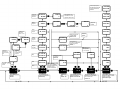
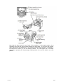
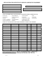
Cooled Incubators
Series 1A, 2, 3 & 4
Programmable
Instruction Manual
1 of 31
01/12
CONTENTS
Section 1:
1.1
1.2
1.3
1.4
1.5
4.0
4.1
4.2
4.3
4.4
5.1
5.2
5.3
6.1
6.2
6.3
6.4
6.5
6.6
2 of 31
21
22
22
22
23-24
Maintenance & Repair
Equipment Ratings
Replacement of Fluorescent Lamps (When Fitted)
Routine Maintenance
Section 6:
10
11
11
11
12
13-14
15
16
16
17
18-20
Optional Extras Where Fitted - All Models
Interior Illumination
Automatic Defrost
High/Low Alarm Option
Inner Perspex Door
Chart Recorder
Section 5:
8
8
9
9
Programming Guide and Examples
Function Overview
Getting Started
Program Run Mode
Display Functions
Example Program
Programmer Function Map
Function List (Level P) Programmer
Memory Allocation Table
Memory Full Indication
Programming Examples
Quick Programming Guide
Section 4:
3
4-6
7
7
7
7
7
Initial Examination and Installation
Commissioning
Controls
Temperature Controller
Indicator & Control Layout
Section 3:
3.0
3.1
3.2
3.3
3.4
3.5
3.6
3.7
3.8
3.9
3.10
Page No.
List of Models
General Details
Introduction
Construction
Temperature Control
Cooling
Air Flow
Section 2:
2.1
2.2
2.3
2.4
General Description
25
25
25
Guarantee
Terms & Conditions for LMS Guarantee
Spares, Servicing & Repairs Contact
Decontamination Notice
Fax Back Guarantee Registration
LMS Services
Application for Servicing
26
27
28
29
30
31
01/12
Instruction Manual for LMS Cooled Incubators
Series 1A, 2, 3 & 4
Series 1A Models
80NP
120NP
201NP
280NP
76 litre capacity
- 120 litre capacity
- 201 litre capacity
- 272 litre capacity
Series 2 Models
210NP
220NP
230NP
240NP
-
135
200
290
420
litre
litre
litre
litre
capacity
capacity
capacity
capacity
Series 3 Models
100NP
200NP
300NP
400NP
- 90 litre capacity
- 227 litre capacity
- 290 litre capacity
- 450 litre capacity
Series 4 Models
600NP
1200NP
3 of 31
- 600 litre capacity
- 1200 litre capacity
01/12
We thank you for purchasing a LMS Cooled Incubator, which we trust, will give you many
years of satisfactory service.
Manufactured in the United Kingdom using the finest materials and modern production
techniques your Cooled Incubator has already undergone extensive testing in our factory.
For correct operation it is essential that you observe the operating and maintenance
instructions in this manual.
LMS, established in 1965 and incorporated in 1979, is a company specialising in
the manufacture and servicing of laboratory equipment, trading principally in the
United Kingdom and Europe as well as throughout the world.
The business is structured into two main sectors:
•
•
Specialist Manufacture of temperature controlled cabinets
Established third party Service, Maintenance & UKAS Accreditations
Manufacture
Specialist manufacture of temperature controlled cabinets with an extensive range of
applications for the testing of products, cultures, plant and insect life etc. over a wide and
closely controlled temperature range.
The design of the purpose built Cooled Incubator facilitates the addition of optional extras to
provide greater flexibility for individual use, making it suitable for a wide range of applications
including: Study of plants and insects
Tissue Culture
Seed germination and vernalisation
Sample storage
Fruit Fly culture
Immunology
Product shelf life tests
Microbiology tests
Service & Maintenance
LMS Limited is an independent third party servicing company which, for over 40 years, has
been providing laboratory engineering services to a wide range of organisations, covering
most makes and types of laboratory equipment and instruments. The broad customer base
covers such diverse operations as: the water industry, commercial, public health and research
laboratories, hospitals, the dairy, food and drink industries, large and small dental, chiropody
and veterinary surgeries etc. LMS Limited is also accredited by UKAS to provide on site
accreditation on the majority of its calibration service.
Among the services provide are: Periodic service and safety inspections
Emergency breakdown cover
Calibration services to traceable standards
Preparation for insurance inspection
UKAS Accreditation (covering: temperature, humidity, rotation, speed and timing)
For a free no obligation quotation for any of the above please complete the details
on the application for Service page and fax to:
LMS LTD
On
01732 450127
4 of 31
01/12
EXPLANATION OF SYMBOLS USED
Electrical Earthing Point
Electrical Hazard Warning
(Mains Electrical Supply Within)
Exhibited where an internal power socket is fitted
Refrigeration Isolation Switch
Auto Defrost On/Off Switch
Weee Label
Serial Number Label
Serial Number Plate
5 of 31
01/12
General Safety Instructions
The physical and chemical properties of your load should be carefully considered with regard
to the effect this may have on the LMS Cooled Incubator. They are not internally sparkfree or
explosion proof. Therefore solvents and/or chemicals which may form a flammable mixture
together with air are unsuitable for these cabinets; otherwise considerable damage can occur.
Transportation
Series 1A & 2
If these cabinets have to be carried it is recommended that at least 2 people
assist and that gloves should be used on all occasions. The cabinet should be
kept upright.
Series 3 & 4:
These cabinets are supplied on pallets and it is recommended that these are
moved by pallet truck or fork lift by competent persons, including someone to
assist in stabilising the load. The cabinet should be kept upright.
Serial Number Plate
The Serial Number Plate contains the year of manufacture, in the following
format: -
xxxx/12xx = year of manufacture 2012
6 of 31
01/12
Section 1
1.1
INTRODUCTION
The LMS programmable option for Cooled Incubators is controlled by a powerful
versatile programmable controller which is designed to offer the highest functionality
and will enable the user to set up and run a complex process relying upon the LMS
reputation for accurate temperature control.
The programmer function is able to control applications needing set point changes
over time. Examples of this are ramp changes where a gradual rate of change can be
set or step changes which are instantaneous. These can be separated by soak
periods during which the process is held at a constant value. Each individual time
interval of the program, or segment, together with its associated moving set point
value, can be stored as a unique program.
At the end of a sequence, a program can be arranged to repeat (or loop), either a
specified number of cycles, or continuously.
For safety reasons, three modes of recovery from power failure are available. These
automatically re-start the program from the beginning, continue it from where it
stopped or hold it, waiting for the user to re-start.
Of course the controller can also be set manually for quick and easy single set point
temperatures if required.
1.2
CONSTRUCTION
The outer casing of all models in Series 1A, 2 and 3 is of sheet steel finished in white
stoved enamel. Models in Series 1A have an internal liner of white pre-coated
Aluminium. The internal liner of models in Series 2 is of a high impact vacuum
formed plastic with a minimum of crevices, and all corners are radiused. Models in
Series 3 have an unobstructed working space fabricated from brushed stainless steel
complete with multi position plastic moulded shelf supports, which allow the three
white plastic coated steel shelves to be randomly positioned to suit individual
requirements. Series 4 models have both a stainless steel exterior and interior and
are supplied with 5 stainless steel shelves (model 600) and 10 stainless steel shelves
(model 1200).
Foam insulation is used, to ensure maximum insulation against external ambient
temperature.
All ranges of LMS cooled incubators incorporate both a door lock and magnetic
gasket with all control features being set into a control panel and positioned so as to
minimise the risk of accidental alteration.
1.3
TEMPERATURE CONTROL
The temperature control method utilises a programmable controller offering digital
selection and readout of temperature. See section 2.3 for operation.
1.4
COOLING
Cooling is provided by a hermetically sealed refrigeration system. All LMS Cooled
Incubators comply with the latest CFC-free regulations.
1.5
AIR FLOW
A full air flow system is used. The airflow being at low velocity but high volume.
7 of 31
01/12
Section 2
2.1
2.2.
INITIAL EXAMINATION AND INSTALLATION
COMMISSIONING
2.1.0
Please check the Tip N Tell indicator on the packaging to ensure the
instrument as not been tipped or laid down. If the blue beads are showing in
the top half of the indicator please refer to LMS Ltd.
2.1.1
Remove all packing materials.
2.1.2
Check for signs of external damage (this MUST be reported
immediately to the Carrier and Supplier).
2.1.3
After the cooled incubator has been sited please allow 24 hours before
switching on.
2.1.4
Check that the electrical supply details on the information Rating Plate, which
is fitted to the rear panel, are in accordance with the available electrical
supply. If correct please use the mains lead supplied, which you will find
inside the cabinet with the user manual.
2.1.5
All cooled incubators are supplied with a 3 pin moulded plug, which if not
suitable may be replaced by an electrician or other competent person.
Connect conductors as follows: BROWN to live, BLUE to neutral,
GREEN/YELLOW to earth.
2.1.6
Position the cooled incubator so that approximately 100mm of free space
exists around the cooled incubator.
2.1.7
Adjust levelling foot or feet (depending on model) so that the cooled
incubator is sited firmly. Lockable castors (where fitted) MUST be locked.
2.1.8
On Series 3 and 4 please ensure that the refrigeration switch, which is fitted
on the rear panel on the right hand side, is in the ON position (down).
2.1.9
On Series 4 place the defrost tray in the rails provided underneath the
cabinet.
CONTROLS – Common to All Models
2.2.1
Fuse
On Series 1A, 2 and 3 all models are fitted with an IEC fused socket, on Series
4 a 1.25" TYPE F cartridge fuse in a screw fitting carrier, both are located on
the rear of the control compartment adjacent to the Serial Number plate on
which the fuse value is indicated.
2.2.2 Non-Adjustable Overheat Protection Device
This device is fitted within the air mixing chamber to safeguard the cooled
incubator should a fault condition of overheating develop. Operation of this
device will be indicated by the Red ‘safety’ neon light on the front panel being
illuminated. In the event of this happening the cooled incubator must be
switched off until the reason for the fault condition is established and the fault
itself is rectified.
8 of 31
01/12
2.3
TEMPERATURE CONTROLLER
LMS Programmable Controller
The Digital Controller has been factory tuned for optimum performance. To obtain a
manual set point temperature press and hold the * button and press either the ▲ or
▼ buttons as required, ▲ to increase temperature, ▼ to decrease. When the
desired set point temperature is achieved, release the * button. The first line of the
controller shows the actual temperature in the chamber and will soon start to change
to the new set point.
For full programming instructions please refer to ‘Section 3’ or use our
quick programming guide at the end of Section 3.
2.4
INDICATOR & CONTROL LAYOUT
Series 1A, 2 and 3
The Red ‘safety’ neon only illuminates when an over temperature fault condition
occurs – see Section 2.2.2.
The Temperature Controller display will be continuously illuminated whilst the
cooled incubator is connected to a mains electrical supply.
Series 4
The Red ‘safety’ neon only illuminates when an over temperature fault condition
occurs – see Section 2.2.2.
The Green neon light and Temperature Controller display will be continuously
illuminated whilst the cooled incubator is connected to a mains electricity supply.
9 of 31
01/12
Section 3
PROGRAMMER
INDEX
Function overview
B.1
Getting started
B.2
Program run mode
B.3
Display functions
B.4
Example program
B.5
Function map
B.6
Function list
B.7
Memory allocation table
Memory full indicator
At the end of a sequence, a Program can be arranged to repeat (Loop), either a specified
number of Cycles, or continuously. Only one Loop can be included in a Program. When the
program is running, the Display indicates progress through the sequence of segments, and
can additionally be interrogated for further segment information.
It is also possible to CALL an already existing program as a sub program that can be
inserted as a segment of another program.
To speed up Program configuration, several Edit functions have been provided so that
individual Segments and Programs may be Deleted or Inserted, and an entire Program
may be Copied and then Pasted into another that it will replace.
B.8
For safety reasons, three modes of recovery from a power failure are available. These either
automatically Re-start the Program from the beginning, Continue it from where it stopped, or
Hold it waiting for a user re-start.
B.9
Programming example
B.10
Program edit example
B.11
In addition to those settings that determine the segment profile, it is also necessary to set
program start values, together with the preferred ramp rate time units for each individual
program.
Either one or both of the two auxiliary outputs can be configured as Event outputs.
Engaging the Holdback feature will temporarily halt Setpoint ramping to allow the process
temperature to catch up should it deviate by more than a pre-set amount during a Ramp
segment.
3.0 FUNCTION OVERVIEW
The Programmer function in Level P enables the instrument to control applications
needing Setpoint changes over time. Examples of this are Ramp changes where a gradual
Rate of change can be set, or Step changes which are instantaneous. These can be
separated by Soak periods during which the process is held at a constant value. Each
individual time interval of the program or Segment, together with it’s associated moving
setpoint value can be stored as a unique Program and for example be represented by the
diagram below.
Setpoint
Soak
Step
To afford maximum programming flexibility, memory is allocated dynamically, and not preallocated. This allows the user the freedom to configure a small number of long programs
or a larger number of shorter ones, up to the permitted maximum of 126 Segments per
program, and a limit of 31 Programs. Should these limits be exceeded, or the Programmer
memory become fully used, the display will read ProG FULL. Programs can be planned
using the Memory Allocation Table which details the memory requirements of individual
segment types. During configuration a check can be kept on memory usage by
interrogating the USEd feature of the display to give an instant reading of ‘percentage
memory used’.
Finally, once a program has been configured, it can be run from the run off/on/hold
controls in Level P, and in addition a quick access run/hold toggle is directly available from
the front panel.
The Programmer Functions List describes the full range of available Settings for each
Programmer Function together with their display mnemonic. The instrument is supplied
with a suite of Factory Settings for each Function. These are shown in bold type.
The Functions Map illustrates the relationship between the Functions and their Settings
and provides a guide to the Keying Operations required to navigate around the menu
when configuring or running a Program.
Ramp
10 of 31
Time (Segments)
01/12
3.1 GETTING STARTED (PROGRAMMER)
Run/Hold Toggle Feature
Press Qt and hold for 3 seconds to hold the program.
Press Qt again and hold for 3 seconds to run the program.
Note: Level P is ‘read only’ while a program is active.
To run a stopped program again press and hold the Qt to toggle RUN ON/OFF/ON again.
New users should take a short time to study the following before starting to configure the
first program, and may wish to take on board the following tips and suggestions.
Program Mode Exit switch (ProG/Auto) Program Level 4.
This standard feature of the instrument causes automatic exit from program mode after
sixty seconds of Key inactivity. It is highly recommended that this setting be disabled and
changed to ProG/StAy to ensure that adequate time is available for making unfamiliar
adjustments.
3.3 DISPLAY FUNCTIONS
Once the program is running, the display automatically tracks the progress of the program as it
indexes through it’s sequence of segments. When it concludes it’s final instruction, the upper
display alternates StoP with the Process Value and the lower display reverts to the instrument
SP1 Setpoint.
RAMP
The upper display alternates between SPr and the moving Process Value while the lower
display shows Target Setpoint. If Holdback is activated, the decimal point in the lower right
corner of the upper display will be illuminated.
Program Parameter List
Listing the required Program Settings and Parameter Values segment by segment beside
each Setting/Segment Number, and Program Display Mnemonic will reduce the risk of
programming mistakes during the learning period.
Memorise Basic Key Functions
Please become familiar with the following Menu Navigation principles
Hold both s and t for three seconds to enter or exit Program Mode.
SOAK
The upper display alternates between SoAK and the Process Value. The lower display
reads the Target Setpoint of the current segment.
STEP (not displayed)
As this involves an instantaneous change of the Target Setpoint, this segment occupies zero
time and the program immediately moves to the next segment. The lower display then
registers the new Target Setpoint, with the upper display alternating in either SPr or SoAK
mode according to the segment configuration.
HOLD
Key either Qs or Qt to view or change settings (follow vertical arrows).
If the program is paused in HOLD, the upper display alternates between hoLd and the
Process Value, while the lower display indicates the Target Setpoint of the current
segment.
Key Q and hold for three seconds to confirm Edit Functions.
User Displays
Key either s or t to view Functions (follow horizontal arrows).
Note: Factory Settings appear in the lower display in each of the Functions illustrated in
the Function Map.
Program configuration
When the PROGRAMMER function is entered at LEVL P, the Programmer is automatically
presented in Configuration Mode, and the instrument display can be used to access and
adjust the various FUNCTIONS.
3.2 Program Run Mode
To run a Program from LEVL P,
Press s once, then use Qs to select the required program number from the PrOG list.
Press s again once then use Qs to select the run/on option.
Press ts and hold for three
11 ofseconds
31 to exit configuration mode and run the program.
With the program running, a further display function is available at any time.
Press and hold Q
Display shows Program Number
Also press s once
Display shows Segment Number
Press s again
Display shows number of loops completed if a loop function has
been set.
Press s again
Upper display reads t.SP
Lower display shows moving Ramp setpoint
Or if in Soak Segment
Upper display reads Sint (Soak interval)
Lower display reads remaining Soak time
Release Q
To return display to Program Run mode
01/12
3.4 EXAMPLE PROGRAM
TYPE
TYPE
TYPE
TYPE
TYPE
TYPE
TYPE
TYPE
TYPE
SPR
SOAK
STEP
SPR
LOOP
SPR
SOAK
STEP
SPR
SPRR
SINT
T.SP
SPRR
PCYC
SPRR
SINT
T.SP
SPRR
105
45
85
55
105
45
85
55
Temp
T.SP
137
Soak Function
Interval: 45 mins
1
T.SP
T.SP
T.SP
30
137
30
Ramp Function
Rate, 105 deg/hour
Target setpoint: 137 deg
Step Function
Target setpoint: 85 deg
Ramp Function
Rate, 55 deg/hour
Target setpoint: 30 deg
STOP
30
Loop Function
Number of repeat
program cycles: 1
SEG
1
SEG
2
SEG
3
SEG
4
SEG
5
SEG
1
SEG
2
SEG
SEG
3
4
Time
12 of 31
01/12
3.5 PROGRAMMER FUNCTION MAP
START HERE
Press and hold
t s
for 3 seconds
ENTER
PROGRAM
Paste only appears
after a program is
copied
Copies the
selected
TUNE
OFF
To add new
program,
press s once
program
EDIT
PSTE
EDIT
COPY
SURE
Q
SURE
Qs
NO
3 secs
3
A copy of program 1 can be
pasted into another program
1
3 secs
PROG
Q
3 secs
Program 1 has
been copied to
program 3
PROG
Q
YES
t
PROG
ADD
Program
RUN
s
OFF
editing
functions.
Insert
EDIT
INS
PROG
Q
2
3 secs
Another program has been
Program 3 has been
inserted into PROG 2
re-numbering existing
PROG 2 to 3
deleted. Display
shows next program
down from top of list
t
LEVL
1
Program
editing
PROG
3
Qt
Add new
programs at
top of existing
menu
functions.
Delete
Hold the
program at
current position
in list
LEVEL P and LEVEL A
LEVL
C
LEVL
P
Q
t
LEVL
A
13 of 31
s
Q
Start program when ‘on’
selected. This locks
other options out
Q
s
PROG
1
Q
t
USED
0
SURE
3 secs
SURE
Qs
NO
YES
Program
‘off’ state
s
Select the required
program number.
Default: 1
PROG
Q
2
3 secs
Hold the
program at
RUN
the point it
stopped
HOLD
FAIL
HOLD
ST.V
SP
Continue the
program
To view existing
If COMMS option
fitted, LEVEL C
appears between
DEL
Program 3
now appears
PROG
2
programs 1 to 31
or full?
EDIT
RUN
from where
it stopped
ON
Q
Reset the
program at
beginning
s
RUN
OFF
s
Select program mode
of operation
Default: off
FAIL
Options: start
program at main
SP or process
CONT
Q
s
FAIL
RSET
SPRU
60 S
variable
s
Power failure recovery
position
Default: reset
Q
Options:
hours
minutes
s
ST.V
PV
s
Select the starting point of
program after power up
Default: PV
Q
s
SPRU
HOUR
s
Ramp rate time units
adjustment
Default: hour
Memory used (%)
01/12
Event output options
energise and de-energise
for all combinations of
SP2 & SP3.
Insert new
segment in
the menu
Delete a
segment
Event
To add new
segments
press s once
SEG
ADD
output
EDIT
DEL
Q
SEG
Q
3 secs
segment 2 becomes 3
SURE
SURE
Qs
NO
YES
Add new
segments at
top of existing
list
SPR
Call up
another
program
Program
re-cycles
Segment 3
now appears
in menu
Step
TYPE
CALL
Ramp
SEG
1 s
Set the segment to be
adjusted
Default: 1
2
3 secs
Define the program
number called
Default: none
SUB.P
NONE
SOAK
Q
s
TYPE
SPR
E.OP
3E
T.SP
9999
Soak time in minutes
or continue
Default: 10
E.OP
2E
HB.V
150
SINT
10
Important note
Up s button must be
used after selecting the
segment type to
confirm it’s selection
s
To select operational
mode of each segment
Default: Ramp
E.OP
2D
Q
SPRR
100
Adjusts ramp
rate
Default: 100
s
s
Q
T.SP
0.0
Target set point adjustable
over the unit’s range
Default: Current main SP
s
Q
HB.V
s
OFF
s
E.OP
s
‘Hold back’ this function only
appears for ramp operational
once a value is set
Default: off
14 of 31
E.OP
3D
‘Hold back band
size adjustable
0.1 to 150 units
TYPE
STEP
SEG
Set Numbers of
re-cycles 1 to 999 unless
full. Or continuous
Default: 1
PCYC
1
TYPE
LOOP
TYPE
Soak
To view existing
segments 1 to 126
or full?
s
E.OP
2E3D
Segment 3
deleted
E.OP
2D3D
SEG
2
Q
SEG
Q
TYPE
E,OP
t
SEG
3
E.OP
2E3E
New segment now
inserted into 2. Old
2
3 secs
Returns to
TYPE
s
EDIT
INS
E.OP
2D3E
NONE
s
Event output - options only
appear when SP2A or SP3A
modes set to E.OP
Default: de-energise
01/12
Function
3.6 FUNCTION LIST (LEVEL P) PROGRAMMER
LEVEL P LEVL
Press s or t to change
Function
TyPE
Press Q s or Q t to change
ProG
Program number
[1]
Add new programs (1 to 31)
run
Run Program
[oFF]
Program not running
on
Run program
hoLd
Pause program
Edit dEL
Delete program
Edit inS
Insert new program
Edit CoPy
Copy another program
Edit PStE
Paste copied program
[rSEt]
Reset to program start
Cont
Continue from interruption
hoLd
Hold at interruption (User re-start)
[PV]
Process value
SP
Setpoint value
[hour]
Ramp rate adjust in hours
60 s
Ramp rate adjust in minutes
[1]
Add new segments (1 to 126) k
SPru
SEG
Press Q s or Q t to change
Define segment type SPr
SPrr
Settings [Factory settings] shown in brackets
Press s or t to change
St.V
Settings [Factory settings] shown
in brackets
P
Access Level P from Level 1. Press and hold Q t
Fail
Sub-functions
Power failure recovery mode
Program start value
Ramp rate time units
Segment number
Ramp to next target setpoint
[100] Setpoint ramp rate Units per
hour/minute (0-9990) (as set at
Spru above)
t.SP
(Segment target setpoint)
adjustable over instrument’s
configured range
hb.u
Hold back [oFF] sets the
permitted band size for the
measured value to deviate from
the ramp setpoint before the
program is ‘held back’ waiting for
the measured value to catch up.
(0.1 to 150 units)
v
SoAK
Sint
StEP
Hold setpoint for pre-set time [10]
Soak time, adjust in minutes
(cont.-1440) x 0.1
Step to new target setpoint (Set
tSP as above)
LooP
PCYC
CALL
Sub.P
Re-cycle program
[1] Set number of program loops
up to 999, or continuous loop k
Call up another program by
number to import into this
program
(nonE) Number of Program called
at Call above
Edit dEL
Delete segment
Edit inS
Insert new segment
v
v Deleting a Program automatically re-numbers those programs with higher numbers
15 of 31
k
Until memory full. See page 14 for further explanation.
01/12
Function
E.oP
Settings [Factory settings] shown in brackets
Press s or t to change
Press Q s or Q t to change
Event output
[nonE]
3.7 Memory Allocation Table
Function can be applied to each
segment independently to trigger
an output at the start of that
segment for the duration of that
segment. Setting blocked unless
either or both outputs SP2A or
SP3A have been configured as an
Event Output in Level 2 or Level A
respectively.
Segment type
Memory required
Ramp
4 Bytes
Ramp with Holdback
5 Bytes
Soak
2 Bytes
Step
3 Bytes
Loops (1-3)
1 Byte
Loops (4+)
2 Bytes
2d
SP2A de-energised to mark event
Call
1 Byte
2E
SP2A energised to mark event
Event Output
1 Byte
3d
SP3A de-energised to mark event
Program Header
1 Byte
3E
SP3A energised to mark event
2d.3d
SP2A and SP3A de-energised to
mark event
2E.3d
SP2A energised SP3A de-energised
to mark event
2E.3E
SP2A and SP3A energised to mark
event
2d.3E
SP2A de-energised SP3A energised
to mark event
To Return to:
Maximum capacity:
351 Bytes
31 Programs
126 Segments
Examples:
1. 1 program of 58 Ramps and 58 Soaks
349 Bytes
2. 4 programs of 14 Ramps and 14 Soaks
340 Bytes
3. 31 programs of 2 Ramps and 1 Soak
341 Bytes
4. 2 programs of 10 Ramps, 10 Soaks, 2 Steps and 1 loop
136 Bytes
LEVL P Press and hold t
3.8 Memory Full Indication
To Read % Programmer memory used:
USEd Press Q and t together in LEVL P / ProG 1
Should the programmer memory capacity be reached during program configuration, the
display will show ‘FULL’
1-100%
16 of 31
01/12
3.9 PROGRAMMING EXAMPLES
SURE
YES
Q
3 secs
PROG
2
Program 1
now pasted
as Program 2
KEY
Arrows drawn thus
signify several key
operations
3.10 Program Edit Function
Make copy of Program 1 and paste as
new Program 2
ADD
PROG(next)
EDIT
COPY Q 3 secs
PROG
1
17 of 31
PSTE
SURE
Q
3 secs
Program settings for functions:
run; FAiL; St.U and SPru
not shown, are all set to Default
Programmer functions
shown as white
characters on black
background
have
Default settings
NO
RUN
OFF
KEY t OR s TO VIEW FUNCTIONS
PROG
1
RUN
OFF
PROG
3
EDIT
SEG
ADD
Program Segment Configuration
See Program 3 illustrated on page 10
SEG
5
TYPE
LOOP
PCYC
1
SEG
4
TYPE
SPR
SPRR
55
SEG
3
TYPE
STEP
SEG
2
TYPE
SOAK
SINT
45
SEG
1
TYPE
SPR
SPRR
10 S
T.SP
30
T.SP
85
T.SP
137
HB.V
OFF
01/12
E.OP
NONE
3.11
Quick Programming Guide
DUAL TEMPERATURE CYCLING WITH LIGHTS ON
In this program we will set the first temperature at 25ºC for a period of twelve hours
with the lights on and the second temperature of 15ºC for a period of twelve hours with
the lights off. This program will also run continuously.
Press and hold both ▲ and ▼ buttons for 3 seconds
Display will read LEUL
P
Press ▲ button, display reads Prog
Add
Press ▲ button until display reads Stu
Pu
Press and hold * and press ▲, display reads Stu
SP
Press ▲ button until display reads SEG
Add
Press ▲ button until display reads type
SPR
Press and hold * and press ▲ button until display reads type
Step
Press ▲ button until display reads t.SP
0.0
(current Set temp.)
Press and hold * and press either ▲ or ▼ button until set-point is reached
25ºC
Press ▲ button until display reads EOP
3D
Press and hold * and press ▲ until display reads EOP
3E
Press ▲ button, display reads SEG
1
Press and hold * and press ▲ button, display reads SEG
Add
18 of 31
01/12
Press ▲ button, display reads type
SPR
Press and hold * and press ▲ button until display reads type
SOAK
Press ▲ button, display reads si.nt
10.0
Press and hold * and press ▲ or ▼ button to change time in minutes you wish
program to run, display reads si.nt
720
Press ▲ button, display reads EOP
3D
Press and hold * and press ▲ button, display reads EOP
3E
Press ▲ button, display reads SEG
2
Press and hold * and press ▲ button, display reads SEG
Add
Press ▲ button, display reads type
SPR
Press and hold * and press ▲ button until display reads type
Step
Press ▲ button, display reads t.SP
0.0
(current set-point)
Press and hold * and press either ▲ or ▼ button until set-point is reached
15ºC
Press ▲ button, display reads EOP
3E
Press and hold * and press ▲button until display reads EOP
3D
Press ▲ button, display reads SEG
3
Press and hold * and press ▲ button, display reads SEG
Add
Press ▲ button, display reads type
SPR
Press and hold * and press ▲ button until display reads type
SOAK
Press ▲ button, display reads si.nt
10.0
19 of 31
01/12
Press and hold * and press ▲ or ▼ button to change time in minutes you wish
program to run, display reads si.nt
720
Press ▲ button, display reads EOP
3D
Press ▲ button, display reads SEG
4
Press and hold * and press ▲ button, display reads SEG
Add
Press ▲ button, display reads type
SPR
Press and hold * and press ▲ button until display reads type
LOOP
Press ▲ button, display reads PCYC
1
Press and hold * and press ▼ button until display reads PCYC
Cont
Press ▲ button, display reads EOP
3D
Press ▲ button until display reads SEG
5
Press and hold both the ▲ and ▼ buttons together for 3 seconds to finish the
programming. The display will return to show Actual and Set-point temperatures.
To Run Program
Press both ▲ and ▼ buttons together for 3 seconds, display reads LEUL
P
Press ▲ button until display reads run
Off
Press and hold * and press ▲ button, display reads run
On
Press both ▲ and ▼ buttons together for 3 seconds. The program will now run
20 of 31
01/12
Section 4
OPTIONAL EXTRAS WHERE FITTED
ALL NON PROGRAMMABLE MODELS
Control Panel
4.0
INTERIOR ILLUMINATION
The interior illumination in these models is either controlled by the programmable
controller, a 24 hour timer or 7 day timer depending on the item fitted to the control
panel.
Where no timer is fitted the controller will need to be programmed for temperature,
time and lights on/off. Please refer to Section 3 or the quick programming guide.
Models fitted with a 24 hour or 7 day time clock, require the segments to be
adjusted, by pulling outwards or pushing in according to requirements. Each small
segment represents 10 minutes on a 24 hour clock and 1 hour on a 7 day clock.
To set the time initially, the clock hands should be turned clockwise only.
Warning: Do Not Turn Hands Anti-Clockwise, as this may damage the clock
When internal illumination switches on during the course of a cycle a slight rise in
cabinet air temperature may be experienced. Where shelf lights are fitted, the rise
will be more pronounced.
21 of 31
01/12
4.1
AUTOMATIC DEFROST
Defrost Controller
On Series 3, and optionally on Series 1A and 2, the cabinet is set to defrost every 6
hours, however the defrost controller will sense whether this is required or not. This
controller is factory set for optimum use and is locked for protection against misuse.
The defrost will give a slight rise in air temperature. If this rise should create any
problems the defrost can be over-ridden by the defrost isolator switch on the rear of
the back panel. On Series 4 the defrost occurs 4 times every 24 hours; duration is
controlled by the ice build up internally.
Please note that this controller will always display the figure 25 which is
not to do with any temperature setting, this is merely a function setting.
On Series 1A, 2 and Series 3 cabinets, any defrost water drains away to a tray
mounted on the compressor. On Series 4 cabinets the water drains into a tray
(supplied) which must be fitted in the special tracks mounted underneath the cooled
incubator during installation. On all models this water evaporates harmlessly away.
4.2
HIGH/LOW ALARM OPTION
The high/low alarm is a manually adjusted alarm option fitted to the instrument’s
front panel. When fitted, this instrument supplements the digital control on the
control panel with a contact thermometer, having a ‘Red’ upper limit pointer and a
‘Green’ lower limit pointer. This unit, being electro-mechanical, is not dependent on
the normal control electronics and therefore will take over control in an emergency
situation and maintain some form of control however coarse.
In the event of an alarm condition, the following action will be taken:
An audible alarm will sound and a secondary safety system will be activated,
preventing the cooled incubator temperature from rising above or falling below the
set alarm limits.
To set up, ensure the pointer is wound well up in the case of the Red and down in
the case of the Green. Set the control temperature by means of the digital controller
and allow the incubator to stabilise at the required control point. Once this is
achieved the pointers may be realigned as close as required to the set point after
making due allowances for contingencies such as door opening etc.
4.3
INNER PERSPEX DOOR
On incubators fitted with this feature and depending on the temperature difference
between the inner working chamber and the space between the inner and outer
doors, some slight distortion may occur to the Perspex door.
22 of 31
01/12
4.4
LMS CHART RECORDER
Chart Paper Loading (see instruction below and illustration on the following page)
1.
Remove front bezel by simultaneously pressing the retaining catches
on each side.
2.
To gain access to the chart paper cassette (1). First unlock the
meter assembly by moving the locking lever (2) to the left and hinge
outwards. Remove cassette by gripping firmly and pulling forward.
3.
To load chart paper. First fit spindle (3) into new roll of chart paper.
Clip roll into spindle retaining slots (4) on the cassette with the paper
unrolling from the bottom. With the chart retaining bracket (5)
lifted, feed the paper onto the sprocketed paper driving wheels (6).
Close chart retaining bracket (5) and check paper feed by operating
the manual feed wheel (7).
4.
Replace cassette to engage chart drive gear (9) and close hinged
meter assembly ensuring that the locking lever (2) latches closed.
Caution: Take care not to damage the meter pointer or imprint stylus when closing
the meter assembly.
Operation (see figure below)
Load chart paper as previously described. If required, the meter pointer/stylus (8)
can be set to mechanical zero, with power off, by carefully turning the zero
adjustment screw (11)
23 of 31
01/12
Note that the stylus may not move freely if the recorder is in the imprint section of its
operating cycle with the stylus pressed against the chart paper. In this case the recorder
chart motor should be operated for a few seconds until the imprint pressure is released, or
the imprint drive wheel (12) can be manually rotated. The chart paper can be manually
advanced by operating the manual paper feeding wheel (7) to set the desired zero time
position.
24 of 31
01/12
Section 5
5.1
MAINTENANCE & REPAIR
EQUIPMENT RATINGS
220/240V AC, 50 Hz. Up to 11 amps max. (see rating plate for details). The cooled
incubator is designed to operate in an environment from +10ºC to +30ºC with a
relative humidity from 5 - 85% RH non-condensing. Correct functionality of the
cooled incubator or its safety features cannot be guaranteed if it is used outside these
ratings.
5.2
REPLACEMENT OF FLUORESCENT LAMPS (WHEN FITTED)
This must be carried out with the mains power switched off and by a competent
person or engineer. Replacement lamps must be of the same size, wattage and
voltage as originals.
5.3
ROUTINE MAINTENANCE
It is recommended that the cooled incubator be inspected annually by a competent
service engineer. The exterior and interior surfaces can be maintained in as new
condition using standard non-abrasive or non-corrosive cleaners. Solvent based
cleaners must not be used. Switch off during all cleaning operations. Allow drying
before switching on. On Series 3 and 4 cabinets, the condenser should be brushed
clean every six months.
A complete defrost is recommended periodically depending on application
To effect a defrost complete the following: A.
B.
C.
D.
E.
25 of 31
Switch off the cooled incubator at the mains switch.
Allow the cooled incubator’s interior to attain ambient temperature by
opening the door.
If necessary, to speed up defrosting, start a heating cycle by setting the
temperature to 35ºC and turning the refrigeration off.
Allow the cabinet to completely dry-out inside before re-using (the process
usually takes 24 hrs).
Please ensure that the cabinet door remains open during this
process.
01/12
Section 6
TERMS AND CONDITIONS
FOR LMS GUARANTEE
6.1.1
Damage on delivery must be reported in writing immediately to LMS.
6.1.2
Equipment must be installed as per instructions.
6.1.3
Equipment must be used, serviced and maintained as per instructions.
6.1.4
Equipment must not be modified electronically or in relation to the refrigeration/air
flow system unless LMS agreement is obtained.
6.1.5
Equipment malfunction under the terms of the guarantee must be reported to LMS.
6.1.6
LMS reserves the right to repair or replace damaged on delivery or malfunctioning
equipment.
6.1.7
If it is found subsequently that the purchaser of the equipment was responsible for
the damage/malfunction a charge will be made by LMS including any carriage
charges.
6.1.8
If it is necessary to return equipment to LMS, the equipment must be packaged so as
to prevent any damage and have a decontamination certificate (see 6.3) showing
that the incubator has been made safe.
6.1.9
Guarantee is for 2 years and cannot be passed on to a subsequent equipment owner.
6.1.10 To register for the 2 year Guarantee please complete and return the enclosed
Guarantee Card or the fax back form in this manual.
In all cases please quote the following details: Model
Serial No.
These details may be obtained from the Serial Number plate on the back of the instrument.
26 of 31
01/12
FOR SPARES, SERVICING AND REPAIRS
6.2
Please contact:
LMS Ltd.
The Modern Forge
Amherst Hill
Riverhead
Sevenoaks
Kent
TN13 2EL
Tel. 01732 451866
Fax. 01732 450127
Email: [email protected]
www.lms.ltd.uk
27 of 31
01/12
6.3
28 of 31
01/12
6.4
Fax Back Guarantee Registration
To qualify for the 2nd year guarantee please fax this form duly completed to
01732 450127
Name:
Address:
Tel No:
Contact Name:
Date Purchased:
Model No:
Serial No:
29 of 31
01/12
6.5
LMS Limited is an independent third party servicing company
which, for over 40 years, has been providing laboratory
engineering services to a wide range of organisations, covering
most makes and types of laboratory equipment.
Among the services provided are:
¾ Periodic service and safety inspection.
¾ Calibration services to traceable standards.
¾ Emergency breakdown cover.
¾ Preparation for insurance inspection.
¾ UKAS Accreditation (covering: temperature, humidity, rotation,
speed and timing).
For a free no obligation quotation for any of the above services
please complete the details on the following page and fax to:
LMS LTD
On
01732 450127
30 of 31
01/12
APPLICATION FOR QUOTATION TO SERVICE LABORATORY EQUIPMENT
NAME OF APPLICANT:
DATE:
COMPANY NAME:
ADDRESS:
TEL NO:
FAX NO:
TYPES OF EQUIPMENT WHICH CAN BE SERVICED, CALIBRATED OR UKAS ACCREDITED BY LMS:AUTOCLAVE
C02 INCUBATOR
GLASS WASHER
PUMP
CENTRIFUGE
DIGESTION BLOCK
INCUBATOR
STERILIZER
CHILLER
FREEZER
LABORATORY FRIDGE
WATER BATH
CLIMATIC CHAMBERS
FRIDGE/FREEZER
LABORATORY OVEN
COOLED INCUBATOR
FURNACE
MEDIA PREPARATOR
PLEASE LIST THESE AND ANY OTHER TYPE OF EQUIPMENT YOU WISH TO BE CONSIDERED
TYPE of EQUIPMENT
MANUFACTURER
MODEL
YEAR
SERIAL NO
UKAS?
PLEASE COMPLETE AND RETURN TO: LMS LTD, THE MODERN FORGE, AMHERST HILL,
FAX: 01732 450127
31 of 31
RIVERHEAD SEVENOAKS, KENT TN13 2EL
01/12


![sf-list [s]](http://vs1.manualzilla.com/store/data/005727021_1-5e70d84b679a2d9887789b982f459474-150x150.png)