1
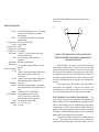
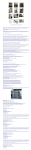
20/20™ DIRECT FIELD MONITOR
20/20p™ POWERED MONITOR
20/20bas™ BIAMPLIFIED SYSTEM
Event Electronics, LLC
P.O. Box 4189
Santa Barbara, CA 93140-4189
Voice: (805) 566-7777
Fax: (805) 566-7771
Web: www.event1.com
E-mail: [email protected]
Your warranty will be in effect when you send in your warranty card
Event, Event Electronics, 20/20, 2020p and 20/20bas are trademarks of Event Electronics, LLC.
Specifications subject to change without notice
© 1996, 1997, 1998 Event Electronics, LLC
Printed in USA
6/98 1127
INTRODUCTION
…………………….……….………….…………….……
1
U NPACKING
……..……………….…………………………………….… 1
SETUP
………………………………….……………….………………… 1
20/20 CONNECTIONS TO AN EXTERNAL
………….………….… 2
AMPLIFIER
20/20bas CONNECTIONS AND OPERATION
………………………….… 3
20/20p CONNECTIONS AND OPERATION
………………………….… 5
CARE AND MAINTENANCE
…………………………………………….… 7
20/20 SPECIFICATIONS
…………………………………..……………… 7
20/20p SPECIFICATIONS
…………………………………………….…
8
20/20bas SPECIFICATIONS
…………………………………………….…
9
INTRODUCTION
Thank you for choosing Event Electronics™ direct field
monitors. Before you proceed, please take a minute to read this manual and
familiarize yourself with the product’s features, set-up and use.
Our engineers have spent over 25 years designing transducers, studio
electronics and high performance studio monitor systems, including some of the
most popular professional speakers used today. Now, using the latest in digital
acoustic design tools along with high performance driver and power amplifier
technology, we’ve developed the Event 20/20, 20/20p and 20/20bas systems,
which extend the performance limits of direct field monitors once again.
For years, small to mid sized monitors have been built using the twoway format employing a 6½-7" diameter woofer. Event engineers have
developed an extended range 8" woofer that precisely blends with our reliable 1"
silk dome high frequency driver to produce an exceptionally smooth frequency
response with the deeper bass and bigger soundfield typical of a larger speaker.
The front-mounted low air restriction bass port also adds to our monitors’ larger
acoustic signature. The 20/20bas Biamplified System monitors build on the
foundation of the passive 20/20 and realize the proven benefits of
biamplification, including lowered distortion, smoother amplitude and phase
response, extended bandwidth and convenience. The unique configuration of
the 20/20p Powered Monitors with its passive crossover provide many of the
performance benefits and all the convenience of a self-powered monitor system
without the high cost.
UNPACKING
Check your speaker carefully. The packing container was
designed to protect your speaker during transit; immediately report any damage
to your dealer or to the company that delivered them to you. Also, please
complete and return your warranty card to activate your warranty and to help us
keep in touch with you. Please tell us what you think of your new monitor and
of your Event dealer.
SETUP
The best performance from any speaker system comes with proper
placement and use. There is no physical or acoustic distinction between
individual left and right monitors when they are used in a stereo pair. Also, the
cabinets can sit vertically or horizontally without concern for performance as
long as both are situated similarly. For horizontal mounting, tip the cabinets
outward so that the high frequency drivers are away from each other. Since the
bass port is front mounted, you can mount the speakers near to, or even in, a
wall without blocking the port.
Place your monitors on a stable surface at about ear level. A typical
location would be slightly behind and to either side of a small console. The
distance between the monitors should equal the distance from the listener to
either speaker. This is the common “equal length triangle” rule for speaker
placement shown in Figure 1.
1
Model 20/20, 20/20p and 20/20bas specifications are subject to change
without notice.
20/20bas SPECIFICATIONS
LF Driver:
HF Driver:
Frequency Response:
Crossover:
Acoustical Crossover:
LF Amplifier Power:
HF Amplifier Power:
Input Connector:
Polarity:
Input Impedance:
Input Sensitivity:
Input Level Control Range:
LF Trim:
HF Trim:
Subsonic Filter:
Protection:
Indicators:
Power Requirements:
Cabinet:
Dimensions:
Weight:
8" mineral filled polypropylene cone with 1½" diameter high
temperature voice coil, damped rubber surround and
magnetic shielding.
1" natural silk dome with ferrofluid voice coil coolant and
magnetic shielding
38Hz - 20kHz, ±2dB, Ref 500Hz
Active fourth order
2.6kHz
130W continuous
70W continuous
Combo XLR - ¼" connector with gold contacts accepts
balanced or unbalanced sources
Positive signal at + input produces outward cone
displacement
40kΩ balanced, 20kΩ unbalanced
1.1V input produces full output with Input Level control at
maximum
20dB
Continuously variable control calibrated in 1dB increments;
Max boost/cut settings produces ±3dB @ 100Hz,
±2dB @ 400Hz
Continuously variable control calibrated in 1dB increments;
Max boost/cut settings produces ±3dB above 2.6kHz
-3dB @ 30Hz
RF interference, output current limiting, over temperature,
turn-on/off transient, subsonic filter, resettable mains circuit
breaker
Combination Power ON / Clip LED indicator
Factory programmed for either 120V~ 60Hz,
220-240V~ 50/60Hz or 100V~ 50/60Hz, 200VA;
Power via detachable 3 circuit IEC type linecord
5/8" vinyl laminated lock-mitered MDF
10¼" W x 14¾" H x 11¾" D
30 lbs. each
9
FIGURE 1. THE PRIME LISTENING POSITION OR SWEET SPOT.
THE DISTANCE BETWEEN EACH SPEAKER AND THE MONITORING
POSITION SHOULD BE EQUAL.
Notice that Figure 1 also shows the speaker cabinets turned inward
directly facing the listening position. This puts you in the sweet spot, which
yields the most accurate stereo reproduction. If you need a wider sweet spot to
allow for greater listener movement or for group monitoring, face the speakers
in a slightly more open position, but never more than necessary. Finally, if you
must mount the speakers substantially above or below ear level, then you will
also need to tilt the cabinets downward or upward as well to keep them directly
facing you.
Once you start using your Event monitors, you may find it helpful to
move around in their soundfield to locate their best position in your
environment, but if you follow the equal distance, ear level, face-on rules,
you’ve already optimized their position for a single user in most situations.
20/20 CONNECTIONS TO AN EXTERNAL POWER AMPLIFIER
The
passive Event 20/20 monitors present a 4 ohm nominal load impedance to the
amplifier. Amplifiers rated for 8 ohm minimum loads are generally not suitable
and may even suffer damage if used. We recommend using a power amplifier
rated in the range of 100-200 watts per channel into 4 ohms. Higher power
amplifiers can be used with caution, but care must be taken to never exceed the
20/20 monitor’s 150W program/200W peak ratings. Event is not responsible for
damage caused by overpowering the speaker’s components.
Connections to the monitors are made via 5-way binding posts on the
rear panel. These terminals will accept large diameter bare or tinned wires,
spade or pin terminals, or banana plugs. Use the shortest length of #10 to #14
gauge speaker wire to connect the positive (red) and negative (black) speaker
terminals to the similarly marked terminals on your power amplifier. Watch for
an accidental polarity reversal . . . it happens! The result will be loss of low
frequency response and center image.
20/20bas’ high frequency output above 2.6kHz by ±3dB to accommodate
personal preferences.
5
POWER SWITCH 1 = ON 0 = OFF
When power is on, the green LED at the front of the speaker will
illuminate.
2
20/20bas BIAMPLIFIED SYSTEM CONNECTIONS AND OPERATION
Please refer to Figure 2.
1
2
INPUT SENSITIVITY This control has a 20dB range and compensates
for different input signal levels. With the control at maximum, 1.1VRMS
input will produce full amplifier output. If too much input signal is
present, the amplifiers may overload, in which case the green LED at the
front of the monitor will flash.
INPUT CONNECTOR This jack has gold plated terminals and accepts
both XLR and ¼" input plugs wired either balanced or single-ended. A 3conductor ¼" TRS or XLR plug is necessary for balanced input
connections, but unbalanced wiring can also use either 3-conductor plug
with the minus input left either unconnected or grounded. A 2-conductor
¼" TS type plug will also work for unbalanced sources, which
automatically grounds the minus input. The input connector wiring is
printed next to the connector and is as follows:
3
20/20p SPECIFICATIONS
LF Driver:
HF Driver:
Frequency Response:
Crossover:
Acoustical Crossover:
Amplifier Power:
Input Connectors:
Polarity:
Input Impedance:
Input Sensitivity:
Input Level Control Range:
LF Trim:
NOTE: Use only good quality input connectors having industry standard
sleeve dimensions. Some consumer grade ¼" TRS plugs do not provide
reliable connections because of slight dimensional differences.
3
4
LOW FREQUENCY TRIM This controls the low frequency shelving
boost/cut filter. The LF Trim filter has effect at frequencies below 400Hz
and is fully engaged below 100Hz as shown on the rear panel response
graphic. When the LF filter is set to “0”, the 20/20bas is designed to
produce a flat LF response in the common “on the bridge or just behind the
console” speaker mounting location. Locating the monitors in-wall or in a
corner may require a reduction of low frequencies while free-standing in
the open may require an increase in low end output for proper tone balance.
The calibrated LF Trim filter allows for personal preferences in any
monitoring situation.
HIGH FREQUENCY TRIM
Use this calibrated control to vary the
HF Trim:
Subsonic Filter:
Protection:
Indicators:
Power Requirements:
Cabinet:
Dimensions:
Weight:
8" mineral filled polypropylene cone with 1½" diameter high
temperature voice coil, damped rubber surround and magnetic
shielding.
1" natural silk dome with ferrofluid voice coil coolant and
magnetic shielding
38Hz - 20kHz, ±2dB, Ref 500Hz
Passive second order
2.2kHz
100W per channel continuous
Combo XLR - ¼" TRS connectors with gold contacts accepts
balanced or unbalanced sources
Positive signal at + input produces outward cone displacement
40kΩ balanced, 20kΩ unbalanced
1.1V input produces full output with Input Level control at
maximum
20dB
Continuously variable control calibrated in 1dB increments;
Max boost/cut settings produces ±3dB @ 100Hz,
±2dB @ 400Hz
Continuously variable control calibrated in 1dB increments;
Max boost/cut settings produces ±3dB above 2.3kHz
-3dB @ 30Hz
RF interference, output current limiting, over temperature, turnon/off transient, subsonic filter, resettable mains breaker
Combination POWER ON / CLIP LED indicator
Factory programmed for either 120V~ 60Hz,
220-240V~ 50/60Hz or 100V~ 50/60Hz, 400VA;
Power via detachable 3 circuit IEC type linecord
5/8" vinyl laminated lock-mitered MDF
10¼" W x 14¾" H x 11¾" D
33 lbs. Powered Main Cabinet;
22 lbs. Passive 20/20 Satellite
20/20p POWERED MONITOR C ONNECTIONS AND OPERATION
Please refer to Figure 3.
8
1
CHANNEL A The Channel A amplifier section powers the external passive
20/20 monitor through the A output connector.
2
CHANNEL B
monitor.
3
7
A OUTPUT
Delivers 100 watts to the companion passive 20/20 monitor.
Use the speaker cable supplied to make this connection observing polarity
(red to red, black to black).
8
POWER SWITCH 1 = ON 0 = OFF
When amplifier power is on, the green LED at the front of the monitor will illuminate.
9
CIRCUIT B REAKER In the unlikely event of a protection or overload condition, the
circuit breaker may open. If this occurs, the center button will pop out. Turn off the
5
Power and reset the breaker by pushing the button back in. Reapply power. If the
breaker opens again you may have a problem requiring attention by qualified
service personnel. DO NOT OPEN THE AMPLIFIER. THERE ARE NO USER
SERVICABLE PARTS INSIDE.
The Channel B amplifier section powers the internal 20/20
INPUT C ONNECTOR This jack has gold plated terminals and accepts both XLR and
¼" input plugs wired either balanced or single-ended. A 3-conductor ¼" TRS or XLR
plug is necessary for balanced input connections, but unbalanced wiring can also use
either 3-conductor plug with the minus input left either unconnected or grounded. A 2conductor ¼" TS type plug will also work for unbalanced sources, which automatically
grounds the minus input. The input connector wiring is printed next to the connector
and is as follows:
NOTE: Use only good quality input connectors having industry standard sleeve
dimensions. Some consumer grade ¼" TRS plugs do not provide reliable connections
because of slight dimensional differences.
4
INPUT SENSITIVITY This control has a 20dB range and compensates for different
input signal levels. With the control at maximum, 1.1VRMS input will produce full
amplifier output. If too much input signal is present, the amplifiers may overload, in
which case the green LED at the front of the powered monitor will flash.
5
HIGH FREQUENCY TRIM Use this calibrated control to vary the 20/20p’s high
frequency output above 2.3kHz by ±3dB to accommodate personal preferences.
6
LOW FREQUENCY TRIM The calibrated LF Trim filter permits adjustments for
personal preferences in any monitoring situation. The LF Trim filter is a shelving
boost/cut filter having effect at frequencies below 400Hz and fully engaged below
100Hz as shown on the rear panel filter tuning graph. When the LF filter is set to “0”,
the 20/20p produces flat LF response in the common “on the bridge or just behind the
console” speaker mounting location. Locating the monitors in-wall or in a corner may
require a reduction of low frequencies while free-standing in the open may require an
increase in low end output for proper tonal balance.
10
POWER C ONNECTOR This connector accepts the detachable linecord. Use the
linecord supplied with your monitors and make sure it is fully seated into the
Power Inlet connector. For safety reasons, do not attempt to defeat the linecord’s
ground connection.
time increasing the resistance of the connection. If you are using banana plugs
on the end of your speaker wires inserted into the binding posts, keep the unused
binding post screw terminals tight. They may rattle or buzz if loose.
Mix at reasonable levels to protect your speakers and your hearing.
service to qualified personnel.
Refer
20/20 SPECIFICATIONS
LF Driver:
HF Driver:
Crossover:
Frequency Response:
Power Handling:
Nominal Impedance:
Sensitivity:
Cabinet:
Connectors:
Polarity:
Dimensions:
Weight:
8" mineral filled polypropylene cone with 1½" diameter high
temperature voice coil, damped rubber surround and magnetic
shielding.
1" natural silk dome with ferrofluid voice coil coolant and
magnetic shielding
2.2kHz, second order
50Hz - 20kHz, ±2dB, Ref 500Hz
150W program, 200W peak
4Ω
88dB @ 1W, 1m
5/8” vinyl laminated lock-mitered MDF
Red and black 5-way binding posts on ¾" centers
Positive signal at red terminal produces outward cone
displacement
10¼" W x 14¾" H x 11¾" D
22 lbs. each
FIGURE 3. THE 20/20p REAR PANEL
6
CARE AND MAINTENANCE Your Event Direct Field Monitors will not
require any special care or maintenance if properly used. The cabinet is finished
with a durable vinyl laminate that can be cleaned with a soft damp cloth. Avoid
touching the exposed speaker elements. Do not expose the rear panel controls,
connectors, or the speaker elements to moisture.
Check the 20/20 and 20/20p’s external speaker wire connections occasionally
for tightness. The bare wires attached to the binding post can become loose over
7
6
CIRCUIT BREAKER In the unlikely event of a protection or overload
condition, the circuit breaker may open. If this occurs, the center button
will pop out. Turn off the power and reset the breaker by pushing the
button back in. Reapply power. If the breaker opens again you may have a
problem requiring attention by qualified service personnel. DO NOT
OPEN THE AMPLIFIER. THERE ARE NO USER SERVICABLE
PARTS INSIDE.
7
POWER CONNECTOR This connector accepts the detachable linecord.
Use the linecord supplied with your monitors and make sure it is fully
seated into the Power Inlet connector. For safety reasons, do not attempt to
defeat the linecord’s ground connection.
FIGURE 2. THE 20/20bas REAR PANEL
4