1
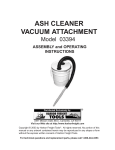
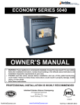
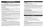
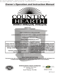
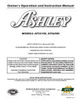
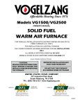
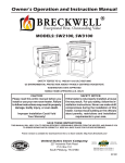
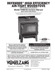
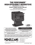
Owner’s Operation and Instruction Manual MODEL: 2200I Fireplace Insert Masonry Fireplace Insert or Zero-Clearance (metal) Fireplace Insert SAFETY TESTED TO UL 1482-2010 and ULC-S628-1993 US ENVIRONMENTAL PROTECTION AGENCY PHASE II CERTIFIED WOODSTOVE DO NOT use this appliance in a mobile home, manufactured home, trailer, or tent. CAUTION! Please read this entire manual before you install and use your new heater. Failure to follow instructions may result in property damage, bodily injury, or even death. SAFETY NOTICE: If this heater is not properly installed, a house fire may result. For your safety, follow the installation instructions. Contact local building or fire officials about restrictions and installation in your area. SAVE THESE INSTRUCTIONS THIS MANUAL WILL HELP YOU TO OBTAIN EFFICIENT, DEPENDABLE SERVICE FROM THE HEATER, AND ENABLE YOU TO ORDER REPAIR PARTS CORRECTLY. KEEP IN A SAFE PLACE FOR FUTURE REFERENCE. STATES ST OV TED NI USSC COMPANY E U French version is available for download from the U. S. Stove website: http://www.usstove.com/ United States Stove Company 227 Industrial Park Road P.O. Box 151 South Pittsburg, TN 37380 1-800-750-2723 C CM US 851892 REV C CONGRATULATIONS! You’ve purchased a heater from North America’s oldest manufacturer of wood burning products. By heating with wood you’re helping to CONSERVE ENERGY! Wood is our only Renewable Energy Resource. Please do your part to preserve our wood supply. Plant at least one tree each year. Future generations will thank you. The instructions pertaining to the installation of your wood stove comply with UL-1482 and ULC-S628 standards. SAFETY INSTRUCTIONS 1. The installation of this appliance must comply with your local building code rulings. 2. DO NOT INSTALL THIS APPLIANCE IN A MOBILE HOME, MANUFACTURED HOME, TRAILER OR TENT (NO EXCEPTIONS PER HUD FEDERAL STANDARD: 24 CFR CH.XX). 3. Verify that the appliance is properly installed before firing for the first time. This appliance should be installed by a qualified installer to insure a correct and safe installation. NEVER use temporary or makeshift compromises during the installation. 4. If there are any missing or damaged components of the appliance, contact your dealer immediately. DO NOT operate this appliance with missing or damaged parts. 5. WARNING: RISK OF FIRE. Observe the minimum clearances to combustibles stated in this manual and on the labels attached to the appliance. DO NOT store wood, any type of flammable vapors or liquids, place furniture, rugs, carpet, clothing or other combustible objects within the clearance area. 6. Do Not connect this appliance to any air distribution duct or system. 7. Do not tamper with the combustion air control of this unit beyond normal adjustment range. 8. Provide adequate combustion air to the room where the appliance is installed. Restricting combustion air will result in a lazy fire which causes soot or creosote buildup and greatly reduces efficiency. 9. Always connect this appliance to a chimney that vents to the outside. Never vent into another room, crawl space, attic, or inside a building. Do not connect this unit to a chimney flue serving another appliance. 10. DO NOT connect a wood burning appliance to an aluminum Type B gas vent. This is not safe. Use approved masonry or a UL 103 HT (U.S.) Listed Residential Type and Building Heating Appliance Chimney. Use a 6” diameter chimney, that is high enough to create sufficient draft. 11. Be sure your chimney is safely constructed and in good repair. Have the chimney inspected by the fire department or a qualified inspector. Your insurance company should be able to recommend a qualified inspector. 12. Creosote or soot may build up in the chimney liner or chimney and cause a house/building fire. Inspect the chimney and chimney liner twice monthly during the heating season and clean if necessary. 13. In the event of a chimney fire, turn the air controls to the closed position, leave the building and call the fire department immediately! 14. To prevent injury, do not allow anyone to use this appliance that is not familiar with its correct operation. Do not operate this appliance while under the influence of alcohol or drugs. 15. Caution: Hot Surfaces. Keep Children Away. Do not touch while in operation. Contact may cause skin burns. 16. Children should be alerted to the hazards from high surface temperatures. Never leave small children unsupervised when they are in the same room as the appliance during operation. To prevent burns, always wear protective clothing, leather hearth gloves, and eye protection when refueling or fire maintenance. Always be aware of heated surfaces. Heat radiating from the appliance can potentially discolor, melt, or even ignite combustible materials. KEEP ALL COMBUSTIBLE MATERIALS WELL AWAY FROM THE HEATER! 17. WARNING: RISK OF FIRE. Keep the feed door tightly closed at all times except when tending the fire. 18. DO NOT overfire this appliance. Overfiring will occur if the feed door is left open during operation. If any part of the appliance glows, you are overfiring. Adjust air controls to a lower setting to slow down the fire. 19. DO NOT Elevate the fire! Build the fire directly on the firebrick. This appliance has not been tested with the use of any means to elevate the fire and it should not be attempted. 20. Ashes should not be allowed to accumulate more than two to three inches in the firebox. 21. The paint on your appliance is durable but will not stand rough handling or abuse. The paint used may give off smoke and/or an odor during the first few fires. This will occur until the paint has cured. Animals / people with lung problems should not be present during the curing process. Build small fires at first to help this process and open windows and doors as needed to clear the smoke and odor. If the appliance is overfired, the paint will discolor. When installing your unit, take care in handling. Clean with soap and water when the appliance is not in use. Do not use any acids, abrasive cleaners or scouring soap as these solvents wear and dull the finish. 22. DO NOT ROUTE THE blower power SUPPLY CORD NEAR OR ACROSS HOT SURFACES! 23. Canada Installations requires that this fireplace must be installed with a continuous chimney liner of 6 inch diameter extending from the fireplace insert to the top of the chimney. The chimney liner must conform to the Class 3 requirements of CAN/ULC-S635, Standard for Lining Systems for Existing Masonry or Factory-Built Chimneys and Vents, or CAN/ ULC-S640, Standard for Lining Systems for New Masonry Chimneys. 24. Permanently seal any opening between the masonry of the fireplace and the facing masonry. 25. Fireplace insert surround panels may be removed to inspect fireplace insert and fireplace. 26. U.S. Stove Company requires installing smoke detectors in the same room as the heater if not already installed. Smoke expelled from the unit by either paint curing, opening the fuel loading door, or a negative pressure inside the home could trigger the smoke detectors. 27. For further information on using your heater safely, obtain a copy of the National Fire Protection Association (NFPA) publication “Using Coal and Wood Stoves Safely” NFPA No. HS-10-1978. The address of the NFPA is 1 Battery March Park, Quincy, MA. 02269. 2Ussc 2200I Dimensions 27 1/32 [686.6 mm] 26 11/32 [669.0 mm] 13 5/32 [334.5 mm] 44 7/32 [1123.0 mm] 6.00 INSIDE 22 1/4 [565.0 mm] 21 13/16 [554.0 mm] 4 11/16 [118.8 mm] 15 1/2 [394.0 mm] Ussc3 PRE-INSTALLATION REQUIREMENTS Fireplace condition and zero clearance requirements A masonry fireplace must meet minimum code requirements, National Fire Protection Association, (NFPA) 211, or the equivalent for a safe installation. Contact a professional, licensed installer, your local building inspector or the local fire authority for the requirements in your area. Your insurance company should be able to recommend a qualified inspector. 6. Fireplace Opening Dimensions. A. Minimum Width................................ 29˝ [737mm] B. Minimum Height............................... 23˝ [584mm] C. Minimum Depth............................... 14˝ [356mm] Inspections should include the following: 1. Condition of the fireplace and chimney. A masonry fireplace and chimney MUST be inspected prior to installation of this appliance. They must be free from cracks, loose mortar, creosote deposits, blockage or other evidence of deterioration. If found, these items MUST be repaired prior to installation. DO NOT REMOVE BRICKS or MORTAR from existing fireplace when installing this unit. 2. Chimney Size. Minimum chimney size is 6˝ (152mm) diameter. Maintain a 15 ft. minimum overall chimney height measured from the top of appliance to the top of the chimney. Chimneys must extend at least 3 ft. above the roof and at least 2 ft. above the highest point within 10 ft. of the chimney top. See the Chimney Connections section of this manual. 3. Zero Clearance or Metal Heatform Fireplaces. These fireplaces and chimneys must meet the minimum code specifications as noted above. Factory built zero clearance fireplaces must be listed and suitable for solid fuel use. Chimneys must be at least 7 inch diameter to accommodate a required, continuous, stainless steel liner from the appliance’s flue collar to the top termination of the chimney. Only detachable parts that can be easily replaced (i.e. damper parts, screens, doors and side, and back refractory panels) are to be removed. These parts must be stored and readily available for replacement if the appliance is ever removed. The removal of any parts that render the fireplace unusable for burning solid fuel requires a permanent label to be affixed by the installer that states the fireplace is unsuitable for burning solid fuel unless the missing parts are replaced and the fireplace is restored to its original, certified condition. 4. Chimney Caps. Mesh type chimney caps and spark arrestors must be able to be removed for regular inspection and cleaning. Otherwise the mesh should be removed to prevent possible plugging. Check your local fire and building codes. 5. Chimney Liner. The chimney must be suitable for burning solid fuel. Install a continuous stainless steel liner from the flue collar of the appliance to the top of the chimney. Liner must be UL Listed to UL1777. 7. Combustible Material Clearances. The fireplace and chimney must be inspected to make sure there is adequate clearance to combustible materials. This includes the top, side, front, and back as well as concealed combustibles in the chimney and mantle areas. Your local building inspector or fire authority should have information on whether older fireplace meet current codes and are suitable for use. See also figure 1 and figure 2. D. Min. Distance to Sidewall...................9˝ [228mm] E. Min. Distance to Top Trim.................14˝ [355mm] F. Min. Distance to Mantle....................19˝ [482mm] G. Min. Distance to Side Trim..................9˝ [228mm] H. Min. Floor Protector Front.................12˝ [304mm] I. Min. Floor Protector Side....................6˝ [152mm] Min. Floor Protector Side Canada ....8” [203] 8. Makeup Air Requirements. This appliance requires an adequate supply of makeup air to operate safely and efficiently. In some areas, this is a building code requirement. Inadequate air supply will cause poor combustion, inefficient operation, creosote buildup, back drafting and smoke puffing into the living areas. If any of the following conditions are evident, a makeup air supply MUST be installed. 4Ussc PRE-INSTALLATION REQUIREMENTS continued... a. Existing fuel-fired equipment shows evidence of back puffing, smoke roll-out, inefficient operation, or excessive smell in the living area. b.Opening a window or door alleviates any of the above problems or symptoms. c. The building is constructed with a well-sealed vapor barrier, tight fitting windows, or has powered exhaust fans. d. Excessive condensation on windows in the winter. e. The building has a ventilation system installed. f. If, once installed, the solid-fuel appliance does not draw steadily, burns poorly or inefficiently, backdrafts or experiences back-puffing when adding fuel. VENTING (DRAFT) REQUIREMENTS The chimney flue is a critical component to the proper and efficient operation of any heating appliance. Heating appliances do not create draft, draft is provided by the chimney. This appliance requires a draft of 0.05 in. water column (0.1 Pa) at the flue collar. WARNING: RISK OF FIRE - EXCESSIVE DRAFT CAN CAUSE OVERFIRING AND A POSSIBLE STRUCTURE FIRE. DO NOT OPERATE THIS APPLIANCE WITH THE FLUE DRAFT EXCEEDING 0.06 in. w.c. (0.1 Pa). To achieve proper draft, your chimney must meet three minimum height requirements; minimum height from top of appliance (15 ft. total height from top of appliance), minimum height above roof penetration (3 ft.), and minimum height (2 ft.) above highest point of roof within a 10 ft. diameter from the chimney. The chimney must also meet minimum and maximum cross sectional requirements. For that reason a continuous 6˝ stainless steel liner from the flue collar to the top of the chimney is required. A stainless steel adapter is recommended for fastening the stainless steel liner to the flue collar. The male (or crimped) end of the adapter must be installed inside the flue collar to allow condensation or creosote in the liner to drain back into the firebox. Chimney liners and/or adapters must be permanently fastened using a minimum of three (3) screws at each connection. Chimneys outside of the home or on an exterior wall are difficult to keep at operating temperatures and may result in increased creosote buildup, less draft, back drafting problems and poor appliance performance and should be avoided. Floor protector A solid non-combustible floor, concrete or solid masonry, must extend 6˝ to either side of the body of the appliance and 12˝ in front of the face of the appliance. When combustible flooring falls within these minimum dimensions, it must be covered with a listed floor protector meeting the requirements of UL 1618, such as Hy-C or Imperial Model UL 2840BK or equivalent with 0.84 Rfactor, 1” thick. (Note: to calculate R-value of alternative materials see Floor Protector Material Calculations at the back of this manual.) A grouted ceramic floor tile that meets local building codes and the minimum 0.84 R-factor requirements is considered a durable equivalent. WARNING: RISK OF FIRE - DO NOT ALLOW COMBUSTIBLE MATERIALS (CARPET, FURNITURE, FUELS) TO BE PLACED ON OR COVER THE FLOOR PROTECTOR. ALL COMBUSTIBLE MATERIALS MUST REMAIN OUTSIDE OF THE MINIMUM CLEARANCE DIMENSIONS. 12 inches [305mm] FLOOR PROTECTOR US - 6 in. [152mm] CAN - 8 in. [203mm] US - 38 inches [965mm] CAN - 42 inches [1.06M] Minimum Floor Protector Specifications US - 6 in. [152mm] CAN - 8 in. [203mm] Ussc5 Assembly Instructions Tools and materials required for installation TOOLS • Pencil • 6 foot Folding Ruler or Measuring Tape • Tin Snips • Drill: Hand or Electric • 1/8” dia. Drill Bit (for sheet metal screws) • Screwdrivers (Blade and Phillips type) • 14mm Nut Driver or Ratchet with 14mm Socket Materials (NOTE: The following items are NOT included with your stove.) Flooring Protection: as specified herein. Chimney Liner: Continuous stainless steel chimney liner (as required) Stainless Steel Adapter (connects the liner to the flue collar) 1/2” Sheet Metal Screws Furnace Cement (manufacturer recommends Rutland Code 78 or equivalent) Caution: THIS APPLIANCE IS HEAVY. MAKE SURE THAT YOU HAVE ADEQUATE HELP AND USE PROPER LIFTING TECHNIQUES WHENEVER MOVING THIS APPLIANCE. 1. Clean the fireplace opening properly disposing of any ashes in a closed metal container. See Safety Instructions. 2. Install a 6˝ (152mm) minimum diameter, continuous stainless steel chimney liner into the existing chimney. The liner must extend to the top of the existing chimney. Use only listed chimney liners that meet UL1777 standards. Follow liner manufacturer installation instructions. 3. Remove or lock the fireplace damper in the open position. Note: Masonry or damper plate may be removed to accommodate the chimney liner provided this does not weaken any structural components of the existing fireplace or chimney nor reduces protection of combustible materials required by national building codes. Consult with your local building or fire authority before doing this. 4. Uncrate the appliance, remove all packing materials, and any items stored in the firebox. 5. WARNING: Any fireplace which has had parts removed or modified to accommodate the installation of this appliance MUST have a warning plate permanently installed in a visible location stating that the fireplace is unfit for use with solid fuel. Permanently attach the warning plate to a visible location in the fireplace. 6. Position the appliance into the fireplace opening until the top lip of the air jacket is flush with the fireplace facing. 8. Level the appliance with the adjusting screws at the rear of the appliance. 9. Connect the chimney liner to the appliance using a stainless steel adapter and securing with a minimum of three (3) sheet metal screws. The liner MUST be attached with the male (or crimped) end of the adapter inside the flue collar of the appliance to allow condensation and/or creosote to drain back into the firebox. 10. Assemble the Surround. Lay pieces face down on carpet or other soft surface to protect finish during assembly. The Surround consists of two side panels, a top panel, and a decorative trim frame. 6Ussc Assembly Instructions continued... 11. Bolt the top panel (1) to the side panels (2) so the top surfaces are flush to one another using items 3 and 4. 12. Assemble the trim frame. The trim consists of a left (6) and right (5) side piece and a split top piece (left #8, right #7). These are joined by corner connectors (1113) and two straight center connectors (9-10). These slide into the channel on the back of the frame and are secured with two set screws (13) in each piece. 11 12 13 8 10 9 1 6 2 5 16. Connect power cord of blower to grounded receptacle. 17.Firebrick extends the life of your stove and radiates heat more evenly. If firebricks were removed to position appliance, replace them before firing appliance. See figure 7 for proper orientation and positioning. Install the back row first, then sides and finally install bottom firebricks. Caution: Risk of Fire! • Replace firebricks before firing woodstove. Position firebricks so no gaps remain between bricks. 7 3 15.The surround assembly is held in place with two springs at the top of either corner of the appliance (figure 6). 4 •Never operate this appliance with missing or cracked firebrick. •Keep furnishings and other combustible materials away from the stove and outside minimum clearances. Figure 7a Back Firebrick Arrangement 2 Firebrick Dimensions: (inches) Five (5) A-Size SURROUND ASSEMBLY VIEW FROM BACK 13. The trim slides over the surround assembly and is secured at the base of each side with a machine screw. 14.The Surround Assembly is then slid over the appliance. Slots in the two side panels accommodate the hood at the top of the appliance (figure 6). Figure 6. Surround Installation SPRING A A A A A A 4.50” x 9.00” B 3.33” x 9.00” C 3.38” x 9.00” D 2.25” x 9.00” E 1.25” x 2.25” Note: All Firebrick is 1.25” Thick B B B Figure 7b Side Firebrick Arrangement Six (6) B-Size B B B SURROUND Slots in surround slide of firebox top C A C A A D A Figure 7c Bottom Firebrick Arrangement Four (4) A-Size Two (2) C-Size One (1) D-Size One (1) E-Size E Ussc7 Chimney Specifications This appliance must be connected to a listed Stainless Steel Liner, that meets UL1777, which extends from the collar to the chimney cap according to the specifications listed on the previous pages. Chimneys perform two functions: 1. As a means of exhausting smoke and flue gases which are the result of fuel combustion. 2. The chimney provides “draft,” which allows oxygen to be continuously introduced into the appliance, so that proper combustion is possible. This stove relies on natural draft to operate. NOTICE: Always provide a source of fresh air into the room where the stove is located. Failure to do so may result in air starvation of other fuel burning appliances and the possible development of hazardous conditions, fire, or death. Your appliance itself does not create draft. Draft is provided by the chimney. To achieve proper draft your chimney must meet the three minimum height requirements detailed in figure 8. A minimum draft of 0.05 w.c. (measured in water column) is required for proper drafting to prevent back puffing, smoke spillage, and to maximize performance. (Gauges to measure draft are readily available at stove stores and are economical to rent or purchase.) Factors such as wind, barometric pressure, trees, terrain and chimney temperature can have an adverse effect on the draft. The manufacturer cannot be held responsible for external factors leading to less than optimal drafting. Should you have a problem with inadequate draft, you should contact a licensed heating and cooling contractor for assistance in solving the problem. IMPORTANT Installation Points 1. Size chimney flue to appliance collar. This stove requires a minimum 6” diameter flue. 2. Never connect this unit to a chimney serving another appliance. 3. The chimney must meet all minimum height requirements. 4. Never use a chimney to ventilate a cellar or basement. 5. Contact your local building authority for approved methods of installation and any necessary permits and/or inspections. Masonry Chimney Before using an existing masonry chimney, clean the chimney, inspect the flue liner, and make any repairs needed to be sure it is safe to use. As mentioned previously, this appliance requires a continuous stainless steel liner from the appliance collar to the chimney cap. Make repairs before attaching the stove. The connector stove pipe and fittings you will need to connect directly to a masonry chimney are detailed in the installation instructions. If the fireplace chimney must go through a combustible wall before entering the main chimney, consult a qualified mason or chimney dealer regarding proper materials that meet all local building and fire authority codes. The installation must conform to local building and fire codes and latest edition of NFPA 211. If there is a cleanout opening in the base of the chimney, close it tightly. 8Ussc FUEL RECOMMENDATIONS WOODSTOVE UTILIZATION Your heating appliance was designed to burn wood only; no other materials should be burned. Waste and other flammable materials should not be burned in your stove. Any type of wood may be used in your stove, but specific varieties have better energy yields than others. Please consult the following table in order to make the best possible choice. TYPE WEIGHT PER CORD EFFICIENCY RANKING SPLITS MILLIONS BTU’s/CORD Hickory 63 4500 1.0 Well 31.5 White Oak 48 4100 .9 Fair 28.6 Red Oak 46 3900 .8 Fair 27.4 Beech 45 3800 .7 Hard 26.8 Sugar Maple 44 3700 .6 Fair 26.2 Black Oak 43 3700 .6 Fair 25.6 Ash 42 3600 .5 Well 25.0 Yellow Birch 40 3400 .4 Hard 23.8 Red Maple 38 3200 .3 Fair 22.6 Paper Birch 37 3100 .3 Easy 22.1 Elm/Sycamore 34 2900 .2 Very Difficult 20.1 Red Spruce 29 1800 .1 Easy 16.1 (LBS. CU. FT., DRY) It is EXTREMELY IMPORTANT that you use DRY WOOD only in your wood stove. The wood should have dried for 9 to 15 months, such that the humidity content (in weight) is reduced below 20% of the weight of the log. It is very important to keep in mind that even if the wood has been cut for one, two, or even more years, it is not necessarily dry, if it has been stored in poor conditions. Under extreme conditions it may rot instead of drying. This point cannot be over stressed; the vast majority of the problems related to the operation of a wood stove is caused by the fact that the wood used was too damp or had dried in poor conditions. These problems can be: - ignition problems - creosote build-up causing chimney fires - low energy yield - blackened windows - incomplete log combustion Smaller pieces of wood will dry faster. All logs exceeding 6” in diameter should be split. The wood should not be stored directly on the ground. Air should circulate through the cord. A 24” to 48” air space should be left between each row of logs, which should be placed in the sunniest location possible. The upper layer of wood should be protected from the element but not the sides. TESTING YOUR WOOD When the stove is thoroughly warmed, place one piece of split wood (about five inches in diameter) parallel to the door on the bed of red embers. Keep the air control full open and close the door. If ignition of the piece is accomplished within 90 seconds from the time it was placed in the stove, your wood is correctly dried. If ignition takes longer, your wood is damp. If your wood hisses and water or vapor escapes at the ends of the piece, your wood is soaked or freshly cut (green). Do not use this wood in your stove. Large amounts of creosote could be deposited in your chimney, creating potential conditions for a chimney fire. Ussc9 operating instructions CAUTIONS: HOUSE FIRE HAZARDS • DO NOT STORE WOOD ON FLOOR PROTECTOR, UNDERNEATH STOVEPIPE(S) IF APPLICABLE, OR ANYWHERE WITHIN CLEARANCES TO COMBUSTIBLE SURFACES SPECIFIED FOR THIS APPLIANCE. • NEVER OPERATE WITH SECONDARY TUBES, FIBER BOARD, OR INSULATION REMOVED. OPERATING SAFETY PRECAUTIONS • NEVER OVERFIRE THIS APPLIANCE BY BUILDING EXCESSIVELY HOT FIRES AS A HOUSE/BUILDING FIRE MAY RESULT. YOU ARE OVERFIRING THE APPLIANCE IF IT BEGINS TO GLOW OR TURN RED. • NEVER BUILD EXCESSIVELY LARGE FIRES IN THIS TYPE OF APPLIANCE AS DAMAGE TO THE FIREBOX OR SMOKE LEAKAGE MAY RESULT. • DO NOT BUILD FIRE TOO CLOSE TO GLASS. • HOT WHILE IN OPERATION. KEEP CHILDREN, CLOTHING, AND FURNITURE AWAY. CONTACT MAY CAUSE SKINS BURNS. DO NOT TOUCH THE APPLIANCE UNTIL IT HAS COOLED. • PROVIDE ADEQUATE AIR FOR COMBUSTION TO THE ROOM WHERE THE APPLIANCE IS INSTALLED. • INSPECT CHIMNEY LINER EVERY 60 DAYS. REPLACE LINER IMMEDIATELY IF IT IS RUSTING OR LEAKING SMOKE INTO THE ROOM. WARNING: EXPLOSION HAZARD • NEVER USE CHEMICALS, GASOLINE, GASOLINE- TYPE LANTERN FUEL, KEROSENE, CHARCOAL LIGHTER FLUID, OR SIMILAR FLAMMABLE LIQUIDS TO START OR “FRESHEN UP” A FIRE IN THE APPLIANCE. • KEEP ALL FLAMMABLE LIQUIDS, ESPECIALLY GASOLINE, OUT OF THE VICINITY OF THE APPLIANCE - WHETHER IN USE OR IN STORAGE. This appliance is designed to burn WOOD FUEL ONLY! Hardwood, 17” to 19”, should be split and air dried (seasoned) for 6 months to obtain maximum burning efficiency. Wood should be stored in a dry, well ventilated area. Burning fuels other than intended, chemicals, or waste in this appliance could result in damages to the heater or result in bodily injury. It will also void any warranty on the appliance. Optimal fuel consumption This appliance is designed to get the most efficient transfer of heat energy from the wood fuel and radiate it into your living environment. The fire box introduces combustion air through three sources; (1) Immediately beneath the door opening below the window is a Lower Primary Air Orifice (LPAO), (2) The door air inlet control brings air into the firebox and controls the rate of burn (and the amount of heat the appliance radiates), (3) The secondary air tubes at the top of the firebox are Notice: use solid wood fuel only! Do not burn garbage , or flammable fluids. Do not use coal. This appliance is not designed to accommodate the air flow (draft) required to properly burn coal or coal products. Do not elevate the fire using grates or irons. Build the fire directly on the firebrick. designed to ignite the combustion gases (smoke) given off by the burning wood and increases the efficiency of the appliance and reduces chimney emissions. Smoke given off by burning fuel consists of very small organic liquid droplets. If these droplets condense, they form a sticky tar-like substance called creosote. When operated properly, this appliance is designed to burn these droplets. Burning these droplets releases heat that would otherwise be lost up the chimney as smoke. Following the instructions below will help you operate your appliance properly to maximize the appliance’s performance. Actual performance is dependent on chimney height, weather, log size, wood species, and moisture content. Some experimentation will initially be required to find that spot where your appliance performs best. The following will give you a starting point to find your optimum settings. When first loading fuel, set the door air inlet control at the wide open position for at least 15–20 minutes. When the appliance is working properly, you should be able to observe secondary combustion flames above the fuel pieces in front of the secondary air tubes at the top of the firebox. These secondary flames should continue to burn after the primary air inlet is reset from wide open to the desired operating setting. If the flames do not continue to burn, open the air control to re-establish the secondary flames then slowly reset the air control to the desired setting. Initially it may take several attempts to figure your appliance out. But once you find the efficient operating spot and the correct mix of procedures to get there, only minor adjustments will be necessary. The best indicator of a properly operating appliance is to look for smoke coming out of the chimney. You may see steam emissions that will quickly dissipate. Smoke will thin but continue to drift without totally disappearing. If you do detect smoke emissions, open the air control a little bit, let the appliance adjust for 10–15 minutes and re-check your chimney. Remember – visible smoke represents lost heat. 10Ussc operating instructions continued... NOTICE - INITIAL BURNS TO CURE PAINT ADDING FUEL BECAUSE OF THE HIGH OPERATING TEMPERATURES, THIS APPLIANCE IS COATED WITH A SPECIAL HIGH TEMP PAINT WHICH REQUIRES A SERIES OF LOW TO MEDIUM BURNS TO FULLY CURE FOR DURABILITY AND A LIFETIME OF SERVICE. If the embers are not hot and glowing, rake the embers to the front of the appliance, close the door and adjust the air inlet control to the wide open position. Let the embers re-heat for 10–15 minutes. When hot and glowing, spread them out and place your next fuel load into the appliance (make sure no embers or ashes block the LPAO). Leave the door air inlet control in the wide open position for 15–20 minutes. Proper curing of the high-temp paint requires a series of three initial burns. The appliance should be allowed to cool off between each burn. The first two burns should be small fires and low temperatures (250 degrees F) for a duration of 20 minutes each. The third fire should be at a temperature of approximately 500 F for 20 minutes. Provide adequate cross ventilation to clear any smoke or odor caused by initial firings. Starting a Fire 1. Set air inlet control to fully open position. 2.Open the door and place several pieces of crushed paper in the firebox. Fuel load size can vary but should be kept 1–2 inches below the secondary air tubes. Also position the fuel to leave space so the air from the inlet can work down between the pieces of fuel. This reduces the time it takes for new fuel to burn properly. 1. When refueling, adjust air inlet control to the fully open position. When fire brightens, slowly and carefully open the door. This procedure will prevent gases from igniting causing smoke and flame spillage. 2. Add fuel being careful not to overload or overfire the appliance. 3. Cover the paper with a generous amount of kindling in a teepee fashion and a few small pieces of wood. 3. When adding fuel be careful not to smother the fire. Do not build fires against glass and make sure the embers do not obstruct the air inlet. Do not allow logs to roll and strike the glass. 4. Ignite the paper and leave the door open slightly. 4. Close the feed door and secure tightly. DO NOT LEAVE APPLIANCE UNATTENDED WITH DOOR OPEN! 5. Adjust the air inlet control as described above. 5. Add large pieces of wood as the fire progresses being careful not to overload. (Do not fill firebox beyond firebrick area.) An ideal ember bed of 1 – 2” should be established to achieve optimum performance. 6. Empty ashes regularly. Do not allow ashes to pile up. 6. This unit is designed to function most effectively when air is allowed to circulate to all areas of the firebox. TIP: If ash or embers remain in the appliance, make sure to clear them away from the Lower Primary Air Orifice (LPAO) and rake a slight (1-to-2 inch wide) trough down the center of the embers from front to back prior to loading the fuel. 7. Once fuel has been loaded, close the door and leave the air inlet control fully open until fire is well established (at least 15–20 minutes) being careful not to over fire (if any of the exterior parts of the appliance or chimney connections begin to glow you are over firing the appliance). 8. Re-adjust the door air inlet control to desired burn rate. (If excessive smoke fills the firebox, open air inlet control slightly until flames resume and wood is sufficiently ignited.) The basic rule of thumb is “closed - low,” “half way open - medium” and “fully open - high.” 7. Properly dispose of hot ashes. 8. Do not overfire the appliance (overfiring is when any part of the appliance’s exterior or chimney connections glow). BLOWER OPERATION The variable speed blower circulates air warmed by the firebox into the living area to distribute the heat more evenly. The blower control knob is located on the side of the blower housing. CAUTION: DO NOT OVERFIRE APPLIANCE. YOU ARE OVERFIRING IF ANY PART OF THE APPLIANCE GLOWS RED. CLOSE THE DOOR AND SHUT DAMPER IMMEDIATELY TO REDUCE THE AIR SUPPLY AND SLOW DOWN THE FIRE. Turn the knob clockwise to turn the blower on. The speed is controlled by turning the knob clockwise for slower speeds and counter-clockwise for faster speeds. To turn the blower off, turn the speed control knob fully counterclockwise. It is recommended to turn the blower off when the unit is not in operation. Ussc11 CHIMNEY MAINTENANCE CAUTION: SLOW BURNING FIRES FOR EXTENDED USE OR BURNING GREEN WOOD MAY CAUSE EXCESSIVE CREOSOTE BUILD-UP. IGNITION OF CREOSOTE OR OVERFIRING COULD CAUSE A CHIMNEY FIRE. CHIMNEY FIRES BURN EXTREMELY HOT AND MAY IGNITE SURROUNDING COMBUSTIBLE MATERIALS. IN CASE OF A CHIMNEY FIRE, CALL THE FIRE DEPARTMENT IMMEDIATELY! CREOSOTE - Formation and Removal When wood is burned slowly, it produces tar and other organic vapors which combine with expelled moisture to form creosote. The creosote vapors condense in the relatively cool chimney flue of a slow-burning fire and can accumulate on the flue lining. If ignited, this creates an extremely hot fire in the chimney which may ignite surrounding materials resulting in a building fire. The chimney connector and chimney should be inspected (at least) twice a month during the heating season to determine if a creosote buildup has occurred. If it has, it should be removed. Failure to remove creosote may result in ignition and may cause a house/building fire. Creosote may be removed using a chimney brush or other commonly available materials from your local hardware retailer. 4. A small hot fire is preferable to a large smoldering one that can deposit creosote within the heating system. 5.Establish a routine for the handling of fuel, wood burner and firing technique. Check daily for creosote buildup until experience shows how often you need to clean for safe operation. Be aware that the hotter the fire, the less creosote is deposited, and weekly cleanings may be necessary in mild weather even though monthly cleanings may be enough in colder months. Chimney Draft NOTE: A DRAFT READING OF 0.05[12.45] to 0.06[14.94] (Water Column[Pascals]) IS REQUIRED FOR PROPER BURNING OF THIS APPLIANCE. Draft is a function of the chimney, NOT THE APPLIANCE — Do not expect the appliance to draw. Smoke spillage into the house or excess buildup of condensation or creosote in the chimney are warnings that the chimney is NOT functioning properly. Correct the problem before using the appliance. Following are some possible causes for improper draft. 1. The connector pipe may be pushed into the chimney too far, stopping the draft. Chimney fires burn very hot. If the unit or chimney connector should glow red, reduce the fire by closing the inlet air control and immediately call the fire department. A fire in the firebox may be smothered by pouring a large quantity of coarse salt, baking soda, or cool ashes on top of the fire. CAUTION: A CHIMNEY FIRE MAY CAUSE IGNITION OF WALL STUDS OR RAFTERS WHICH WERE ASSUMED TO BE A SAFE DISTANCE AWAY FROM THE CHIMNEY. IF A CHIMNEY FIRE OCCURS, HAVE YOUR CHIMNEY INSPECTED BY A QUALIFIED EXPERT BEFORE USING AGAIN. PREVENTING CREOSOTE BUILD-UP 1. Burn with air control open for several minutes at numerous intervals throughout the day during the heating season, being careful not to overfire the unit. 2.Burn appliance with air inlet control wide open for 15–20 minutes every time you apply fresh wood. This allows wood to achieve the charcoal stage faster and burns wood vapors which might otherwise be deposited within the heating system. 2.If the chimney is operating too cool, water will condense in the chimney and run back into the appliance. Creosote formation will be rapid and may block the chimney. Operate the appliance at a fire level high enough to keep the chimney warm preventing this condensation. 3. If the fire burns well but sometimes creates excessive smoke or burns slowly, it may be caused by the chimney top being lower than another part of the house or a nearby tree. The wind blowing over a house or tree falls on top of the chimney like water over a dam, beating down the smoke. The top of the chimney should be at least three (3) feet above the roof and be at least two (2) feet higher than any point of the roof within ten (10) feet. 3. BURN ONLY SEASONED WOOD. Avoid burning wet or green wood. Seasoned wood has been dried for at least one year. 12Ussc service hints ASH REMOVAL AND DISPOSAL GLASS Replacement Ashes should be removed from the stove every few days or when ashes get to 2 to 3 inches deep. Always empty the stove when it is cold, such as in the morning. Ashes should be placed in a metal container with a tight fitting lid. The closed container of ashes should be placed on a non combustible floor or on the ground, well away from all combustible materials, pending final disposal. If the ashes are disposed of by burial in soil or otherwise locally dispersed, they should be retained in the close container until all cinders have thoroughly cooled. Other waste shall not be placed in this container. 1. Ensure appliance is not in operation and is thoroughly cooled. GLASS CARE The following usage and safety tips should be observed: 1.Inspect the glass regularly for cracks and breaks. If you detect a crack or break, extinguish the fire immediately and contact the manufacturer for a replacement. 2. Do not slam the door or otherwise impact the glass. When closing doors, make sure that logs or other objects do not protrude to impact the glass. 3. Do not build fires against (or that might fall against) the glass. 4. Do not clean the glass with materials that may scratch (or otherwise damage) the glass. Scratches on the glass can develop into cracks or breaks during operation. 2. Remove screw and glass clip. (See parts list and diagram.) 3. Lift glass out from glass clip. 4. Remove old gasket and clean glass. 5.Replace new gasket starting at the bottom of glass working along edges, being sure to center gasket channel on glass. 6. Trim to length and butt ends together. 7. Replace glass into door, being sure not to overtighten screw and clip. After extensive use, the gasket material which provides glass and door seal may lose it’s resiliency and will need to be replaced. Inspect glass and door gaskets periodically to ensure proper seal; if gaskets become frayed or worn, replace immediately. DOOR GASKET REPLACEMENT 1. Ensure appliance is not in operation and is thoroughly cooled. 2. Remove old door gasket and clean channel. 3. Using an approved, high temperature gasket cement, apply a thin coat in bottom of channel. 5. Never attempt to clean the glass while the unit is hot. If deposits are not very heavy, normal glass cleaners are adequate using a soft, non-abrasive cleaning pad. Heavier deposits may be removed with oven cleaners. 4. Starting at hinge side of door, work gasket into channel around door unit, end butt and trim to length. 6. Never put substances which can ignite explosively in the unit. Even small explosions in confined areas can blow out the glass. Removing the Insert for purpose of inspection. Gasket and Glass cleaning products are available at local retail home centers. Manufacturers of cleaning products for wood stoves include, A.W. Perkins Co. (www.awperkins.com) or Rutland Products (www.rutland.com). CAUTION: R E P L A C E G L A S S O N LY W I T H 5 m m H I G H TEMPERATURE CERAMIC GLASS OF THE PROPER SIZE. DO NOT USE TEMPERED GLASS OR DOUBLE THICKNESS WINDOW GLASS. 5. Close door and allow three to four hours for cement to set before firing appliance. If for any reason you must remove the insert for inspection of the appliance or fireplace, follow these rules. 1. Ensure appliance is not in operation and is thoroughly cooled. 2. Remove the surround by removing the springs retaining it to the appliance. 3. Disconnect the flue gas pipe from the appliance. 4. Slide appliance out to perform inspection. Ussc13 REPAIR PARTS 19 17 16 18 10 14 12 29 14 13 6 27 15 11 30 26 7 28 31 5 3 32 4 2 22 1 21 24 9 23 8 20 25 Key Part No. Description Qty. 1 2 3 4 5 6 7 8 9 10 11 12 13 14 15 16 69660 88066 891813 88087 25465 83202 83278 891373 25080 89066 891989-1 891414 891989-2 86669 86670 891990 Complete Door Assembly 5/8” Rope Gasket Door Glass Glass Gasket Glass Retainers Machine Screw - 10-24 x 3/8 Ph Hd. Washer - 7/32 ID X 1/2 OD Hinge Pad Door Latch (Uses 83508 - 5/16-18 x 3/4 bolt) Firebrick (4.5 x 9) Firebrick (3.33 x 9) Firebrick (2.25 x 9) Firebrick (1.25 x 2.25) Tube #1, Secondary Comb. Tube #2, Secondary Comb. Retainer, Tube 1 6 ft. 1 4 ft. 2 4 4 2 1 9 6 1 1 2 1 3 Key Part No. 17 18 19 20 21 22 23 24 25 26 27 28 29 30 31 32 88158 88159 88160 80598 891991-1 891991-2 891991-3 83913 891992-1 891992-2 891992-3 891992-4 891993 Description Fiber Board, Front Fiber Board, Rear Fiber Blanket Blower Assembly Surround, Top Surround, Left Side Surround, Right Side Spring Trim-R, Surround Trim-L, Surround Trim-Top_L, Surround Trim-Top_R, Surround Key, Straight Key, Blank Straight Key, Blank Corner (Can Use 89420) Key, Corner (Can Use 89419) Qty. 1 1 1 1 1 1 1 2 1 1 1 1 1 1 2 2 14Ussc FLOOR PROTECTOR The stove must be placed on solid concrete, solid masonry, or when installed on a combustible floor, on a Type 2 floor protector listed to standard UL 1618 with a minimum R value of 1.2 or equivalent. The floor protector is required to provide heat, live ember, and ash protection and must be of a non-combustible, continuous solid surface to protect against infiltration of live embers and ash. For UL Listed floor protectors, refer to manufacturers instructions for installation directions. Manufacturers of listed floor protectors include Imperial Metal Products and Hy-C among others. To calculate R-Values for alternative methods, see below for calculation methods. Alternate materials may be rated with C-factor (Thermal Conductance) or k-factor (Thermal Conductivity) ratings which must be converted to R-value to determine if the alternate material meets the tested requirements. The following instructions provide the proper information and formulas for conversion to R-value. To determine if alternate materials are acceptable follow this sequence. 1. Convert material specifications to R-value: a. R-value given — no conversion necessary b. k-factor is given with a required thickness (T) in inches: R = 1/k x T c. C-factor is given: R = 1/C 2. Determine the R-value of proposed alternate floor protector: a. Use formulas in step 1 above to calculate R-value of proposed material(s). b. For multiple layers, add R-values of each layer to determine overall R-value. 3. If the overall R-value of the floor protector system is equal to or greater than the floor protector specifications given, the alternate is acceptable. Definitions: BTU Thermal conductance (C) = (hr)(ft²)(°F) = (Btu)(inch) Thermal conductivity (k) = (hr)(ft²)(°F) W = (m²)(°K) (hr)(ft²)(°F) Thermal resistance (R) = BTU = W (m²)(°K) = BTU (hr)(ft²)(°F) (m²)(°K) W Example: The specs of floor protector material should be 3/4-inch thick material with a k-factor of 0.84. The proposed alternative material is 4” brick with a C-factor of 1.25 over 1/8-inch mineral board with a k-factor of 0.29. Step 1: Convert specs to R-value. R = 1/k x T = 1/0.84 x 0.75 = 0.893 System must have a R-value of 0.893 = Rspecs Step 2: Calculate R-value of individual components 4” Brick with C-factor = 1.25. R = 1/C = 1/1.25 = 0.80 = Rbrick 1/8-inch (0.125”) mineral board with k-factor = 0.29. R = 1/0.29 x 0.125 = 0.431 = Rmin.brd. Step 3: Add R-values of components to get total R-value of system Rbrick + Rmin.brd = 0.80 + 0.431 = 1.231 = Rsystem Step 4: Compare Rsystem to Rspecs Rsystem = 1.231 is larger than Rspecs of 0.893. System R-value exceeds the required specifications and therefore is an acceptable alternative. Ussc15 Certification Label 16Ussc Notes / Sketches Ussc17 how to order repair parts this manual will help you obtain efficient, dependable service from your heater, and enable you to order repair parts correctly. Keep this manual in a safe place for future reference. When writing, always give the full model number which is on the nameplate attached to the heater. when ordering repair parts, always give the following information as shown in this list: 1. The part number 2. the part description 3. the model number: 2200I 4. the serial number:____________________ united states stove company 227 industrial park road p.o. box 151 south pittsburg, tn 37380 (423) 837-2100 WWW.USSTOVE.COM 18Ussc CUT HERE " WARRANTY INFORMATION CARD Name______________________________________ Telephone #: (_____)_____________ City______________________________________ State_______ Zip_________________ Email Address ____________________________________________________________ Model # of Unit_____________________________ Serial #___________________________ Fuel Type: qWood qCoal qPellet qGas qOther ______________________ Place of Purchase (Retailer)___________________________________________________ City__________________________________________ State_______ Zip_________________ If internet purchase, please list website address___________________________________ Date of Purchase __________________________________________________________ Reason for Purchase: qDecoration qAlternative Heat qCost qMain Heat Source qOther _________________________ What was the determining factor for purchasing your new appliance?_______ I have read the owner’s manual that accompanies this unit and fully understand the: Installation q Operation q and Maintenance q of my new appliance. Print Name Signature Date Please attach a copy of your purchase receipt. " CUT HERE Warranty not valid without a Proof of Purchase. Warranty information must be received within 30 days of original purchase. Detach this page from this manual, fold in half with this page to the inside and tape together. Apply a stamp and mail to the address provided. You may use an envelope if you choose. You may register online by going to www.usstove.com All information submitted will be kept strictly confidential. Information provided will not be sold for advertising purposes. Contact information will be used solely for the purpose of product notifications. Ussc19 CUT HERE " Ê Fold Here Fold Here É Place Stamp Here " CUT HERE United States Stove Company P.O. Box 151 South Pittsburg, TN 37380 20Ussc