1
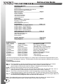
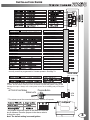
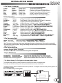
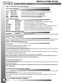
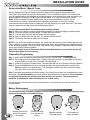
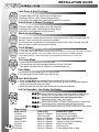
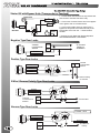
FCC/ID Notice
This device complies with Part 15 of the FCC rules. Operation is
subject to the following conditions:
(1) This device may not cause harmful interference, and
(2) This device must accept any interference received, including
interference that may cause undesired operation.
CAUTION: Changes or modifications not expressly approved by the
part responsible for compliance void the user’s authority to operate
this devise.
INSTALLATION GUIDE
TABLE OF CONTENTS
2250 Wiring Diagram
Pre-Installation
Components
Recommended Pre-Installation Procedures
Recommended Install Procedures
Wire Connectors
6 Pin Connector
14 Pin Connector
3 Pin Red Connector
4 Pin Blue Connector
Jumper Selections
Installation
Basic Installation - Quick start
Plugging In The Module
Auto Tach Learn
Shock Sensor Programming
Programming
Program Overview & System Reset
Program Menu 1 (User Settings)
Program Menu 2 (Alarm Settings)
Program Menu 3 (Starter Settings)
Program Menu 4 (Tach Settings)
Other Features And Operations
Reservation Mode
Transmitter Programming
Battery Replacement
Service Mode
System Operation
Relay Diagrams
Page 3
Page 4
Page 5
Page 6
Page 7-11
Page 12
Page 14-15
Page 16
DIAGNOSTICS
PARK LIGHTS
3 Flashes
3 Slow Flashes
4 Slow Flashes
5 Flashes
5 Slow Flashes
6 Flashes
6 Slow Flashes
7 Flashes
8 Flashes
STATUS LED
Series of 3 Flashes
No Flashes
Series of 4 Flashes
Series of 5 Flashes
Series of 5 Flashes
Series of 6 Flashes
Series of 6 Flashes
Series of 7 Flashes
Series of 8 Flashes
DIAGNOSTIC CODE
Door Opened “M” Models
Attempted Start - In Service Mode
Not in Reservation Mode “M” unit
Hood Pin Grounded (Open)
Brake Pedal Shutdown
Ignition On During Start Attempt
Hood Pin Grounded
Tach Lock-Out
3 Start Attempts with no start
If the remote starter has a failed start attempt or if a safety input is activated the Diagnostic Memory will
store up to four shutdowns in memory. This information can then be accessed to determine the source of
the shutdown.
To Enter Diagnostic Mode:
Step 1 - Turn the ignition on wait two seconds then turn off. Press the Program Button and release.
Step 2 - The system will respond with three park light flashes and the siren will chirp the
same number of times as the events in memory. ( Maximum four events, four chirps)
NOTE: If the siren does not chirp, there are no events in memory.
Step 3 - Press the Program Button once to view the last shut down code. The siren will chirp once to
confirm code one. (If the siren does not chirp, there are no codes in memory).
Step 4 - The LED’s on the antenna will flash a code corresponding to a shut down trigger. Press the
Program Button again to check the second code. The siren will chirp twice to confirm code two.
Step 5 - To Clear Diagnostic Memory. While in Diagnostic Mode press and hold the Program Button for
five seconds. The park lights will flash and the siren will chirp once.
Note: Once diagnostic memory has 4 improper shutdown events in memory, the system will not
record any further shutdown events until the system memory has been cleared.
2
INSTALLATION GUIDE
WIRING DIAGRAM
YELLOW
RED/WHITE
BROWN
ORANGE
WHITE/BLUE
BLACK/WHITE
PURPLE
WHITE
GREEN/WHITE
GREEN
BLACK
PINK
BLUE/WHITE
BLUE
*This input is a optional connection for “TL” models. This input is programmable
and may need to be programmed for Tachless operation. See Page 11.
SIDE VIEW
Note: The center pin of this connector is low current and designed to power a Voltage
Inverter. Do not use the center pin of this connector to power relay packs. Doing so will
damage the output. *Always use a fused power source when installing relays for keyless
entry.
ACTIVE RF ANTENNA
Program Button
Status Led’s
4 PIN
Blue
**The antenna must be connected before the system will operate
Jumpers
The jumpers control the output on the white wire from the
six pin harness. Place the jumpers in the above order to
change the output.
Note: The default setting is second ignition.
3
INSTALLATION GUIDE
INSTALLATION TIPS
Components
- Control module
- Remote transmitter(s)
- Antenna with built in program button and LED’s
- 6 pin main harness with dual 30amp power inputs
- 14 pin harness
- 3 pin - 2 wire keyless entry harness
- Multi-tone siren
- Hood pin safety switch
- Hood and window stickers
- Installation guide
- Owners manual
Recommended Pre-Installation Procedures
BEFORE STARTING INSTALLATION:
- Discuss the optional features with the customer.
- Take a few minutes to review the installation and owners manuals.
- Check if the vehicle has a factory security or anti-theft system.
*If equipped, inform the customer of addition parts and labour.
- Do a walk around the vehicle and check for any damage.
- If installing a LED discuss the placement with customer before installing.
Note: This remote starter is designed for fuel injected and diesel engines.
Recommended Installation Procedures
Proper Connections - Remote Starters can handle loads of up to 30 amps for extended periods of time. It is CRITICAL to
insure that ALL high current connections are properly soldered and insulated with quality electrical tape. Failing to insure proper
connections will result in warranty being VOID and can result in a FIRE. The manufacturer is not responsible for any such
damages. It only takes a few more minutes to do the job RIGHT.
Under Hood Connections - Route the hood pin and tach wires through the firewall into the engine compartment. Always try to
pull the wires through a factory rubber grommet. If drilling through the firewall, BE CAREFUL. Check for obstructions on both
sides of the firewall. After drilling use a snap in grommet to protect the wires from sharp edges.
Installing the External Long Range Antenna - To insure the best possible reception, place the antenna in the center of the
windshield, behind the rear view mirror. Before attaching to the glass ensure that the surface is clean and dry. For best results
with range, place the antenna below the tint screen. Run the cable under the headliner and behind the A-pillar panel. Be careful
not to pinch the antenna cable. Plug the antenna into the BLUE connector on the Control Module.
NOTE: This step is not used on Alarm Only Units with no External Antenna.
Mounting The Control Module - Never mount the module in the engine compartment. Select a location under the dash to
install the main module. Be certain that the module is securely attached and does not obstruct any serviceable areas. Do not
force or jam the module into tight places instead of mounting. The module must be free from all moving parts such as brake,
clutch and gas pedal linkages. Do not place the module directly in front of a heater vent.
Testing The System - When the installation is complete, it will be necessary to test that the system is working correctly. The
system’s default programming will work on the majority of vehicles, but might need to be adjusted for some applications. If the
installation requires special timing or additional features, proceed to Program Mode.
ATTENTION: The Hood Pin Safety Switch MUST always be connected!!
NOTE: Always inform user to place system in Service Mode before any service
Work is performed on the vehicle.
INSTALLATION GUIDE
WIRING CONNECTIONS
6 Pin Power Connector
Yellow
Green
Red
Red
Blue
White
Starter
Heater
12 power
12 power
Ignition 1
Select Out
30amp output
30amp output
30amp input
30amp input
30amp output
30amp output
12volts during crank only.
12volts in accessory. Off during start.
Constant 12volt power at ignition harness.
Constant 12volt power at ignition harness.
12volts in ignition and start positions.
Selectable Output. See jumper diagram.
14 Pin Connector
Yellow
Red/White
Brown
Orange
White/Blue
Black/White
Purple
White
Green/White
Green
Black
Pink
Blue/White
Blue
Re-Arm
3rd CH
Disarm
(-) Output
Siren / Horn
Park Brake
(+) Door Input
Park Lights
Hood Pin
(-) Door
Ground
Brake
Tach
Glow Plug
0.75sec Pulse With Lock And On Shutdown.
Trunk Release - Active When Button #2 Is Held For 3seconds.
0.75sec Pulse With Unlock And Before Start.
(-) While Running / (-) While Locked - **Starter Program Mode.
(+) Siren / Horn Output - **User & Alarm Program Modes.
Negative Park Brake Input - Manual Transmission Models Only.
Positive Door Trigger Input - Manual Trans & Alarm Units Only.
Positive Park light Output - 10 Amp Max.
Negative Hood Pin Input - MUST BE CONNECTED!!
Negative Door Trigger Input - Manual Trans& Alarm Units Only
System Ground Input - MUST BE CONNECTED!!
Positive Brake Input - MUST BE CONNECTED!!
Tach Signal Input - MUST BE CONNECTED ON TACH MODELS!!!
Programmable Input - DIESEL ONLY. **Starter Program Mode.
3 Pin Connector Red
Green Door Lock
Blue
Door Unlock
Door Lock Output - Programmable - Menu 1 Setting 3.
Door Unlock Output - Programmable - Menu 1 Setting 3.
Note: The center pin of this relay is low current and designed to power a voltage inverter. Do not use the center pin of
this connector to power relay packs. Doing so will damage the output. Always use a fused power source when installing
relays for keyless entry.
4 Pin Connector Blue
Antenna/ Program Button Connector.
The Antenna Must Be Connected Before the System will Operate.
Jumper Selections
Position One Second Starter
Position Two Second Accessory
Position Three Second Ignition*
Output On the White Wire From The 6-Pin Connector.
Output On The White Wire From The 6-Pin Connector.
Output On The White Wire From The 6-Pin Connector.
* The Default Setting For The System Is Second Ignition Output.
To change the jumper position you must first remove the access cover as shown in the diagram below.
The access cover will slide out of its position when pushed outwards from the center of the module.
The jumpers control the output on the white wire from the six pin harness. To change the output of this wire, place the jumper in one
of the following positions
Note: The default setting is second ignition.
INSTALLATION GUIDE
QUICK START INSTALL
Step 1 - Connect All Of the Following Wires
6 Pin Power Connector
Yellow
Green
Red
Red
Blue
White
Starter Output
Heater Output
12 power Input
12 power Input
Ignition 1 Output
Selectable Output
Connect The Yellow Wire From The 6 Pin To The Vehicles Starter Wire.
Connect The Green Wire From The 6 Pin To The VehiclesAccessory Wire.
Connect to Constant 12 Volt Power Source- High Current.
Connect to Constant 12 Volt Power Source- High Current.
Connect The Blue Wire To the Vehicles Primary Ignition Wire.
Select Jumper Position (If Necessary). See Page 5.
14 Pin Power Connector
Black
Pink
White
Green/White
Blue/White
White/Blue
Green or(-)
Purple(+)
System Ground
Brake Switch
Park Lights
Hood Switch
Tach Input
Siren / Horn
Door Input
Door Input
Connect The Black Wire To Chassis Ground.
Connect The Pink Wire To The Brake Switch (+) When Brake is Applied.
Connect The White Wire To (+) Park Light System.
Connect The Green/White Wire To The Hood Pin Switch.
Connect The Blue/White Wire To AnA/C Tach Source.(Must Be Above 2volts A/C)
Connect The White/Blue Wire To A (+) Siren or To A (+) Horn Wire.
Connect The Green Wire On Vehicles With Negative Door Pin Systems.
Connect The Purple Wire On Vehicle With Positive Door Pin Systems.
Manual Transmissions Only
Black/White
Park Brake
Connect (-) Parking Brake
Manual transmission vehicles must have a “M” Series Remote Starter Installed. Manual Transmission Units Must Be Placed Into
Reservation Mode To Operate. See Page 12.
Step 2- Plug-In The Module
When all the connections are done, the control module can be plugged in. Before connecting the control module, make sure the
ignition is in the OFF position. Plug in the 6 pin harness then the 14 pin followed by any other connectors that were used.
Step 3- Auto Tach/Tachless Learn
Tach Learning
1) Make all the required wire connections and plug-in the Unit.
**The park lights should flash twice upon power up.
2) Turn the Ignition Key ON. (The Park Lights will turn on).
3) Start the vehicle with the key, the LED’s on antenna will come when proper tach signal is detected. After 30 seconds the park
lights will turn off then flash twice to confirm Tach learning.
* The system will flash the park lights seven times if not Tach/ Tachless learned and the start button is pressed. The system must
be Tach/ Tachless learned before remote starting.
** If the LED’s do not come on during tach learn, a proper Tach signal was not detected.
Note: If the park lights do not flash in auto tach learn mode it may be necessary to connect to a different tach source.
For best results connect the tach to the coil pack or to a fuel injector wire.
Tachless Learning (TL Models Only)
1) Follow Steps 1&2 from above.
2) Start the vehicle with the key, the LED’s on antenna will turn on after 30 seconds then park lights will turn off then flash twice to
confirm Tachless learning.
Note: If the first ignition wire is connected to a wire that does not stay 12 volts in the start position the system will not
Tach/ Tachless learn.
Activate Self Learning Impact Sensor
1) Press the LOCK button on the remote 5 times in a row, once every half second. The siren will chirp 3 times and the park lights
will come and stay on solid.
2) While the park lights are on, strike the vehicle at the desired level to trigger the alarm.
3) The siren will respond with one chirp to confirm that the Shock Sensor is programmed. Strike the vehicle 3 times to set the
impact level.
4) Press the lock or unlock button to exit Shock Sensor learning.
Your Basic Install Is Complete!
INSTALLATION GUIDE
PROGRAMMING
Programming Overview
Program mode allows you to adjust the settings and options of your system.
Your system has been intelligently designed by installers with years of experience. The system’s default settings do not require any
program changes in most cases. However, this system does incorporate a highly advanced programming system that includes 4
menus with numerous options and settings that can be easily adjusted for custom installations and applications.
Menu 1 - User Settings - Page 8
This program menu contains settings that adjust the way the system operates for the user.
Menu 2 - Alarm Settings - Page 9
This program menu contains settings that adjust the way the system operates for the user.
Menu 3 - Starter Settings - Page 10
This menu controls features and settings associated with remote car starter applications.
Menu 4 - Tach Settings - Page 11
This menu allows the programming of the tach signal and the manual adjustment of that setting.
Entering Program Mode
To Enter Program Mode
1) Make sure ignition is in the off position.
2) Within three seconds turn the key ON - OFF - ON - OFF - ON. Leave in the “ON” position.
3) Press and release the Program Button on the antenna one time.
4) The park lights will come on and the siren will chirp to confirm entering Program Mode.
5) Select the Desired Program Menu:
Press Button #1 Lock
User
Options
Page 8
Press Button #2 Unlock
Alarm
Options
Page 9
Press Button #3 Start
Remote Start
Options
Page 10
Press Button #4 Aux
Tach Adjustment Menu
Page 11
6) The selected mode will be confirmed by a siren chirp and one park light flash.
7) The Program Menu may be changed at any time by pressing the transmitter buttons as above, this allows the installer to
change a setting from one menu, then quickly jump to another menu without re-entering the Program Mode.
8) To exit Program Mode, turn the ignition key “OFF” or wait 30 second and the system will exit automatically.
Note: If the unit does not enter Program Mode, turn the ignition off for five seconds and repeat steps 1-4.
** The first ignition(Blue wire) MUST be connected to the vehicle’s first ignition wire. If it is not connected it will not be possible to
enter the Program Modes.
Changing the Programmable Settings
To Select and Change A Program Setting:
1) Enter Program Mode.
2) Select the desired Program Menu. (See pages 8 - 11)
3) Press & release the Program Button the correct number of times to select the desired Program Setting(as listed on pages 8 11). The park lights will flash and the siren will chirp to indicate the current setting that is selected.
4) Press and hold the Program Button until the parking lights / siren confirm the selected setting. The park lights will flash and the
siren will chirp to indicate the option selected within the setting.
5) Turn the ignition key “Off” to exit Program Mode.
Note: This procedure is listed below each program setting on pages 8 - 11 of this manual.
SYSTEM RESET
STEP 1 - Within three seconds turn the key ON-OFF-ON-OFF-ON (Leaving Key ON).
STEP 2 - Press and release the Program Button.
STEP 3 -The park Lights will turn ON.
STEP 4 - Press and hold the program button again for 8 seconds until the park lights flash and the siren will chirps three times.
The system is now re-set to factory defaults.
Note: Reset to defaults resets the tach learning and any setting that may have been changed
in the program menus but does not delete the transmitters from memory.
INSTALLATION GUIDE
PROGRAMMING
PROGRAM MODE - USER SETTINGS
Setting 1- Ignition Auto Lock
1 Ignition Lock & Unlock Enabled
2 Ignition Lock Only
*3 Ignition Auto Lock Disabled
1 Light Flash
2 Light Flashes
3 Light Flashes
Doors Lock / Unlock when the key is turned On/ Off
Doors Lock when ignition key is turned ON only
Doors do not Lock or Unlock with Ignition key
Press the Program Button 1 time to select setting 1 (This will be confirmed by 1 LED flash)
Press and hold the Program Button until you receive the appropriate # of park light flashes and siren chirps.
Release the Program Button . Press momentarily to move to next program step or repeat to change selection.
Setting 2- Horn Honk Settings
1 Lock & Unlock chirps Disabled
2 Lock & Unlock chirps Enabled
*3 All chirps enabled
1 Flash
2 Flashes
3 Flashes
Honks for Panic and Car Finder Mode only.
Honks for Lock, Unlock, Panic and Car Finder Mode Only.
Honks for Lock, Unlock, Start, Panic and Car Finder Mode.
Press the Program Button 2 times to select setting 2 (This will be confirmed by 2 LED flashes)
Press and hold the Program Button until you receive the appropriate # of park light flashes and siren chirps.
Release the Program Button . Press momentarily to move to next program step or repeat to change selection.
Setting 3- Door Lock Options
1 Double Pulse Unlock
2 3 Second Lock & Unlock
*3 0.75 Second Pulses
1 Flash
2 Flashes
3 Flashes
Single .75sec.Lock pulse and double Unlock Pulse
3 second pulses for Lock & Unlock
0.75 second pulses for Lock and Unlock
Press the Program Button 3 times to select setting 3 (This will be confirmed by 3 LED flashes)
Press and hold the Program Button until you receive the appropriate # of park light flashes and siren chirps.
Release the Program Button . Press momentarily to move to next program step or repeat to change selection.
Note: See Setting 7 to adjust the door lock pulse duration to 125ms.
Setting 4 -Sensor - Enable / Disable
1 Sensors Disabled
* 2 Sensors Enabled
1 Flash
2 Flashes
Impact Sensors Disabled
Impact Sensors Enabled - Normal Operation
Press the Program Button 4 times to select setting 4 (This will be confirmed by 4 LED flashes)
Press and hold the Program Button until you receive the appropriate # of park light flashes and siren chirps.
Release the Program Button . Press momentarily to move to next program step or repeat to change selection.
Setting 5 - Passive / Active Arming
1 Passive Arming
2 Active Arming With Rearm
* 3 Active Armin
1 Flash
2 Flashes
3 Flashes
Auto Arms 30 seconds after last door is closed
If unlock is pressed and no door is opened within 30sec
Alarm Arms Only with Transmitter
Press the Program Button 5 times to select setting 5 (This will be confirmed by 5 LED flashes)
Press and hold the Program Button until you receive the appropriate # of park light flashes and siren chirps.
Release the Program Button . Press momentarily to move to next program step or repeat to change selection.
Setting 6 - Active / Passive Locks
1 No Auto-Lock with Passive Arm
*2 Doors Auto-Lock with Passive
1 Flash
2 Flashes
Doors do not auto-lock with passive arming
DOORS LOCK WHEN PASSIVE ARMING
Press the Program Button 6 times to select setting 6 (This will be confirmed by 6 LED flashes)
Press and hold the Program Button until you receive the appropriate # of park light flashes and siren chirps.
Release the Program Button . Press momentarily to move to next program step or repeat to change selection.
Setting 7 - Door Unlock & Disarm Pulse Duration
1 Short Pulses
2* Normal
1 Flash
2 Flashes
125ms pulses with Unlock and on disarm output. (.125 second)
750ms pulses with Lock, Unlock and on disarm output. (.75 second)
Press the Program Button 7 times to select setting 7 (This will be confirmed by 7 LED flashes)
Press and hold the Program Button until you receive the appropriate # of park light flashes and siren chirps.
Release the Program Button . Press momentarily to move to next program step or repeat to change selection.
Note: Programming this option will change the pulse length of this output from 750ms to a
Much shorter pulse of 125ms.
INSTALLATION GUIDE
PROGRAMMING
PROGRAM MODE - ALARM SETTINGS
Enter Alarm Program Mode - See Page 7 for details on entering program mode
Setting 1 - Secure Valet Mode
1 Secure Valet Active
2* Normal Valet Active
1 Flash
2 Flashes
Valet only if ignition “ON” and Program Button is held for 15 seconds
Valet if ignition “ON” and Program Button is held for 5 seconds
Press the Program Button 1 time to select setting 1 (This will be confirmed by 1 LED flash)
Press and hold the Program Button until you receive the appropriate # of park light flashes and siren chirps.
Release the Program Button . Press momentarily to move to next program step or repeat to change selection.
Setting 2 - Parking Light Output
1 30 Second Parking Lights on Disarm
2 Negative Park Light
3* Normal Parking Lights
1 Flash
2 Flashes
3 Flashes
Park Lights on for 30 seconds on disarm
Switches the Park Light and the Trunk Release (3rd Ch) Outputs
2 Park Light Flashes on disarm
Press the Program Button 2 times to select setting 2 (This will be confirmed by 2 LED flashes)
Press and hold the Program Button until you receive the appropriate # of park light flashes and siren chirps.
Release the Program Button . Press momentarily to move to next program step or repeat to change selection.
Setting 3 Horn Honk Timing - Unit Must be set for Horn Output in Setting 5
1 5ms
2 20ms
*3 10ms
1 Flash
2 Flashes
3 Flashes
Short (Quiet) Pulses
Long (Loud) Pulses
Normal (Medium) Pulses
Press the Program Button 3 times to select setting 3 (This will be confirmed by 3 LED flashes)
Press and hold the Program Button until you receive the appropriate # of park light flashes and siren chirps.
Release the Program Button . Press momentarily to move to next program step or repeat to change selection.
Setting 4 Car Jack Mode
1Door & Button
2Door, Button 4
*3 Car Jack OFF
1 Flash
2 Flashes
3 Flashes
Activated by pressing Button #4 or opening the door while the Ignition is “ON”
Activated by pressing Button #4 or opening the door while the Ignition is “ON”
No Car Jack
Press the Program Button 4 times to select setting 4 (This will be confirmed by 4 LED flashes)
Press and hold the Program Button until you receive the appropriate # of park light flashes and siren chirps.
Release the Program Button . Press momentarily to move to next program step or repeat to change selection.
Setting 5 Siren / Horn Output
1 Horn Honk
*2 Siren Output
1 Flash
2 Flashes
Pulses when alarm is triggered - Timing can be programmed by Setting 4
Output on steady when alarm is triggered
Press the Program Button 5 times to select setting 5 (This will be confirmed by 5 LED flashes)
Press and hold the Program Button until you receive the appropriate # of park light flashes and siren chirps.
Release the Program Button . Press momentarily to move to next program step or repeat to change selection.
INSTALLATION GUIDE
PROGRAMMING
PROGRAM MODE - STARTER SETTINGS
Setting 1- Special Door Lock/ Unlock Operations
1 Type 1
2 Type 2
3* Normal Operation
1 Flash
2 Flashes
3 Flashes
Unlock before start and a lock pulse after start & shutdown
Lock pulse after remote starter shuts off
No additional re-lock pulses
Press the Program Button 1 time to select setting 1 (This will be confirmed by 1 LED flash)
Press and hold the Program Button until you receive the appropriate # of park light flashes and siren chirps.
Release the Program Button . Press momentarily to move to next program step or repeat to change selection.
Setting 2- Gas/ Diesel Mode- Blue Wire on 14-Pin
1Negative Input/ 30seconds 1 Flash
2Timed Delay/ 15 Seconds 2 Flashes
3* Gas/ Positive Glow Plug 3 Flashes
Waits a maximum 30 seconds before starting.
Ignition ON for 15 seconds before engaging remote starter
Waits 2 seconds to start if no diesel input is detected
Press the Program Button 2 times to select setting 2 (This will be confirmed by 2 LED flashes)
Press and hold the Program Button until you receive the appropriate # of park light flashes and siren chirps.
Release the Program Button . Press momentarily to move to next program step or repeat to change selection.
Setting 3- Rearm Output- Yellow Wire on 14-Pin
1 Type 1
1 Flash
Pulse after start and with lock
2 Type 2
2 Flashes
Pulse after start only
3* Factory Re-arm
3 Flashes
0.75 second pulse with lock and after shutdown
Press the Program Button 3 times to select setting 3 (This will be confirmed by 3 LED flashes)
Press and hold the Program Button until you receive the appropriate # of park light flashes and siren chirps.
Release the Program Button . Press momentarily to move to next program step or repeat to change selection.
Setting 4- Run Time
1 30 Min Run Time
1 Flash
Remote Starter runs for 30min when activated
2 45 Min Run Time
2 Flashes
Remote Starter runs for 45min when activated
3* 15 Min Run Time
3 Flashes
Remote Starter runs for 15 min when activated
Press the Program Button 4 times to select setting 4 (This will be confirmed by 4 LED flashes)
Press and hold the Program Button until you receive the appropriate # of park light flashes and siren chirps.
Release the Program Button . Press momentarily to move to next program step or repeat to change selection.
Setting 5-Maximum Crank Time
110 Seconds
1 Flash
10 sec Max time that starter will stay engaged
23 Seconds
2 Flashes
3 sec Max time that starter will stay engaged
3* 5 seconds
3 Flashes
5 sec Max time that starter will stay engaged
Press the Program Button 5 times to select setting 5 (This will be confirmed by 5 LED flashes)
Press and hold the Program Button until you receive the appropriate # of park light flashes and siren chirps.
Release the Program Button . Press momentarily to move to next program step or repeat to change selection.
Setting 6- Starter Kill/ Bypass Module Output- Orange wire on 14-Pin Con.
1 Active Starter Kill
1 Flash
On when locked, Before ignition and 2 seconds after ignition turns off.
2 Passive Starter Kill
2 Flashes
Same as setting 1 but will arm 60sec after the ignition turns off.
3* Bypass Module
3 Flashes
Output before ignition. Stays on 2 seconds after ignition turns off.
Press the Program Button 6 times to select setting 6 (This will be confirmed by 6 LED flashes)
Press and hold the Program Button until you receive the appropriate # of park light flashes and siren chirps.
Release the Program Button . Press momentarily to move to next program step or repeat to change selection.
Setting 7- Safety Start Mode
1 Safety ON
2* Safety OFF
1 Flash
2 Flashes
Must press the start button twice to remote start vehicle
Press the start button once to remote start vehicle.
Press the Program Button 7 times to select setting 7 (This will be confirmed by 7 LED flashes)
Press and hold the Program Button until you receive the appropriate # of park light flashes and siren chirps.
Release the Program Button . Press momentarily to move to next program step or repeat to change selection.
INSTALLATION GUIDE
PROGRAMMING
PROGRAM MODE - TACH SETTINGS
Setting 1- Tach Selection (TL Models Only)
1* Tach Detection Mode
1 Honk/Chirp
Must connect Tach Wire. (Blue/White on 14-pin connector)
2 Tachless Mode
2 Honks/Chirps
No Tach connection required. (Do not connect the tach wire)
Note: The system must be Tach/Tachless learned before the vehicle will remote start.
Setting 1- Method 2- Low Idle Tach Learning
This option is used for vehicles that maintain a HIGH or erratic idle after starting and need more that 10
seconds to establish a stable idle.
Step 1 - Enter Program Mode (Ignition ON-OFF-ON-OFF-ON) then press the Program button on the antenna 1 time.
Step 2 - Enter Program Menu 4 - Press button #4 on the remote transmitter.(# Button)
Step 3 - Start Vehicle - Using the ignition key, make sure not to turn the key off at any time or your will exit programming.
Step 4 - Press the Program Button - One time ( The Led will start flashing in single cycles) Press and hold the Program
Button for 5 seconds. The park lights will flash twice when the tach signal is learned.
Setting 2- Adjust For Over-Crank (Tach or Tachless)
Step 1 - Enter Program Mode (Ignition ON-OFF-ON-OFF-ON) then press the Program button on the antenna 1 time.
Step 2 - Enter Program Menu 4 - Press button #4 on the remote transmitter. (# Button).
Step 3 - Press the Program Button - 2 times (The Led will start flashing 2 times).
Step 4 - Hold the Program Button - For 5 seconds until parking lights flash (each time lights flash the tach is reduced)
Step 5 - Release the Program Button - Exit Program Mode and test the remote start.
Setting 3- Adjust For Under-Crank (Tach or Tachless)
Step 1 - Enter Program Mode (Ignition ON-OFF-ON-OFF-ON) then press the Program button on the antenna 1 time.
Step 2 - Enter Program Menu 4 - Press button #4 on the remote transmitter. (# Button)
Step 3 - Press the Program Button - 3 times (The Led will start flashing 3 times).
Step 4 - Hold the Program Button - For 5 seconds until parking lights flash (each time lights flash the tach is increased).
Step 5 - Release the Program Button - Exit Program Mode and test the remote start.
Shock Sensor - Self Learn Mode
5 times
1. Press the LOCK button 5 times, once every second.
2. The system will chirp the siren 3 times upon last press and the park lights will flash 3
times then stay “On” during the adjustment mode.
3. Within 10 seconds impact the vehicle three times with the amount of force you want
to activate alarm. The siren will chirp upon sensing the impact.
4. Press the unlock button to exit Adjustment Mode.
5. Arm the system, wait 10 seconds and test sensor.
Note: Repeat the above steps to adjust the setting of the sensor.
Anti Car Jacking Mode
ENSURE THAT USER IS FULLY TRAINED ON THIS FEATURE!
ONLY USE THIS FEATURE WHEN SPECIFICALLY REQUESTED. ENSURE THAT USER IS TRAINED ON
THE OPERATION OF THIS FEATURE IF NOT, UNWANTED RESULTS MAY ARISE.
When activated, the system waits 30 seconds then flashes LED rapidly for 30 seconds, then chirps
siren as a warning for 10 seconds then goes into full alarm .
ACTIVATING CAR JACK MODEProgrammable - Mode 1, Mode 2
Activates upon any of the following steps:
- Mode 1 & 2
While the ignition Key is “On” press and release button #4.
- Mode 1 & 2
Open the vehicles door while the ignition key is “On”.
- Mode 2 only
Each and every time that the ignition key is turned “On”
DEACTIVATING CAR JACK MODE
1. During countdown - Turn ignition”off & on” then press and release the Program Button.
2. After full alarm - Turn ignition “off & on” the hold the Program Button for 8 seconds.
INSTALLATION GUIDE
OPERATIONS
Reservation Mode - Manual Trans.
Manual Transmission Remote Starters must have both the door trigger and park brake wires
connected. Most installs will require a clutch bypass. This is a temporary bypass. The clutch should
only be bypassed during the activation of the remote starter. Never disconnect or alter the switch to be
always bypassed. Always use a “M” Series Remote Starter on a manual transmission vehicle.
Never install a automatic Remote Starter model into a manual transmission vehicle. It is not
recommended to install a remote starter on a convertible type vehicle. If doing so It is highly
recommended that a radar sensor is installed to cover the proximity of the gear shift lever. If the radar
sensor is tripped the remote starter will exit Reservation Mode.
To enter Reservation Mode, the following steps must be followed.
Step 1 - While the vehicle is running, place the transmission in neutral and apply the parking brake.
Step 2 - Press and release the brake pedal. The park lights will activate.
Step 3 - Turn the ignition key off and the vehicle will stay running.
Step 4 - Exit the vehicle and close the door. The vehicle will then shut off.
Step 5 - The vehicle can now be safely remote started.
NOTE: If the vehicle has a dome light delay, the vehicle may stay running until the dome light turns off.
This is normally no longer than 30 seconds. Reservation Mode will automatically be exited if the doors
of the vehicle are opened. The set-up mode will then have to be repeated . Reservation Mode Must be
set-up each time the vehicle is parked.
Note: If the vehicle is not in Reservation Mode and the Start button is pressed, the system will
flash the park lights four times slowly.
Transmitter Programming
Step 1 - Within three seconds turn the ignition Key ON-OFF-ON-OFF-ON - Leaving Key ON
Step 2 - Press and hold the Program button - Parking Lights will come ON **if park lights do not come
on at this point, turn key off for 5 seconds, the repeat step 1.
Step 3 - Continue to hold the Program button. The park lights will turn on.(Continue holding the Button)
Step 4 - Press the LOCK button on each of 1st car remote’s and press the # button on each of the
2nd car remote’s to be programmed. The park lights will flash once and the siren will chirp
once each time a new code is learned.
Note: Transmitter programming must done quickly. Do not pause more than one second between each
transmitter. All the transmitters to be used must be programmed at the same time. All transmitters
not programmed at this time will be erased from memory for security. The system holds a
maximum of 4 transmitter codes including 2nd car remote codes.
You can program the same remote as a 1st car remote in one vehicle and as a 2nd car remote in a
second vehicle.
Battery Replacement
The transmitter battery should be changed at least once every year to maintain proper operating range.
Replace with quality23A 12volt Alkaline battery.
Carefully remove the
screw from back of
the remote.
+
-
Remove top case
then replace the
battery.
Replace top case.
Re-install screw.
Test remote for
proper operation.
INSTALLATION GUIDE
OPERATIONS
System Service Mode
ACTIVATING SERVICE MODE
1. While the ignition is “ON” press and hold the Program Button for five seconds. The park lights will
flash and the siren will chirp five times to confirm that the system is in Service Mode.
2. While in Service Mode the remote start functions will be disabled and LED’s will be “ON” steady. Door
locks and trunk release are still operational.
DEACTIVATING SERVICE MODE
1. While the ignition is “ON” press and hold the Program Button for five seconds. The park lights will flash
and the siren will chirp two times to confirm that the system has exited Service Mode.
2. Remote start functions will return to normal operation.
Service Mode- By Remote
SERVICE MODE ACTIVATED
1 - Press and release button 4 (# Button)
2 - Press and hold Button 4 (# Button) for 6 seconds until Status LED comes on Steady
Note: The siren will chirp 5 times to confirm Service Mode was entered.
SERVICE MODE DEACTIVATED
1 - Press and release Button 4 (# Button)
2 - Press and hold Button 4 (# Button) for 6 seconds until Status LED turns off.
Note: The siren will chirp 2 times to confirm Service Mode was exited.
Note: The remote starter will flash the park lights 3 times if the start button is pressed when the
vehicle is in Service Mode.
LIMITED LIFETIME WARRANTY
Limited Lifetime Warranty - Available with Professional Installation Only
The manufacturer warrants to the original purchaser of their remote starters and alarms, that the product shall be free from defects in material and workmanship.
However, should this product be proven to be defective, within a three year period from the original date of purchase, the manufacturer will, without charge to the
purchaser (excluding any charges incurred to have the product delivered to the manufacturer) , repair or replace any part of the remote starter and/or alarm which
the manufacturer agrees to be defective. After the initial three-year period a labour charge of no greater than $20.00 will apply to all defective goods. A $20.00
check must accompany any goods being returned to the manufacturer. All warranties apply on to the original purchaser and the vehicle in which it is originally
installed. Repairs or replacement of defective modules shall remain at the discretion of the manufacturer. All other parts, components, accessories and/or optional
equipment pertaining to the remote starter and alarm are not included in the manufacturer's warranty. This warranty is non-transferable. Request for warranty
service from any Factory Authorized Dealer must be accompanied with the original purchase receipt or have product registered by authorized dealer on
manufacturer's website. Failure to comply with any of these conditions may result in warranty being voided. If unit in not installed by an Authorized Dealer warranty
term is limited to 15 day from date of purchase and covers manufacturing defects ONLY. Only freight pre-paid shipments will be accepted for warranty,
This warranty does not cover the following: removal and reinstall labor charges, shipping charges, abuse, misuse, or accidental damages to the remote starter and
alarm, automobile, and/or parts there of. This warranty is void upon modification, repairs, or alterations of any part of the System. The manufacturer does not
guarantee or insure against theft of the vehicle or its contents. Alarm models are designed only to act as a deterrent against possible theft. This alarm may qualify
for auto insurance discounts; contact your Insurance Agent for further information. The manufacturer shall not be held liable for any consequential damages due to
breach of this or any other warranty, expressed, or implied. This warranty gives you specific legal rights. Your specific legal rights may vary for each region.
CERTAIN DAMAGES EXCLUDED - The manufacturer expressly disclaims any liability or responsibility for incidental damages caused by the product, including
economic loss, loss of use of the product, car rentals, or any other costs relating to the care and custody of the product. The manufacturer disclaims liability or
responsibility for any consequential damages caused by the product or resulting from its use, including the cost of repairing or replacing other property damaged by
the product or caused by its use, whether or not the product is working properly. The product is intended to deter unauthorized use of the vehicles in which it is
installed. The manufacturer does not warrant that the product is fool-safe against theft and/or vandalism and/or human error or misuse. The manufacturer accepts
no liability or responsibility for any damage of any kind whatsoever caused to any vehicle in which the product is installed or any resulting damage from its use. The
manufacturer accepts no responsibility or liability for any damage resulting to or theft of the vehicle or its contents.
INSTALLATION GUIDE
OPERATIONS
Lock Doors & Arm The Alarm
1.Press and release the LOCK button on the remote transmitter.
2.The park lights will flash and the siren will chirp once.
3.The doors will lock. (With Optional Keyless Entry)
4.The LED’s on the antenna will start flashing within five seconds.
Unlock Doors & Disarm The Alarm
1.Press and release the UNLOCK button on the remote transmitter.
2.The park lights will flash and the siren will chirp twice.
3.The doors will unlock. (With Optional Keyless Entry)
4.The LED’s on the antenna will stop flashing.
Silent Arm And Disarm
1.Press and release the LOCK & UNLOCK buttons at the same time.
2.If the doors are locked this will unlock the doors without siren chirps, the park lights will
flash two times to confirm the doors have unlocked.
3.If the doors are unlocked this will lock the doors without siren chirps, the park lights will
flash one time to confirm the doors have locked.
Trunk Release
1.Press and hold the UNLOCK button for three seconds.
2. The doors will unlock, continue holding the unlock button for three more seconds, the trunk
release will then activate. The trunk release will be confirmed by one park light flash.
3.For safety reasons, trunk release will not activate when ignition key is in the “On”
position.
Car Finder Mode
2 sec.
1. Press and hold the # button for two seconds.
2. The system will flash the park lights and chirp the siren five times.
**This feature can help find your vehicle in a crowded parking lot.
Panic Mode
1.Press and hold the LOCK button for three seconds.
2.The park lights will flash and the siren will activate.
3 sec.
PANIC MODE DISABLE
1. Press the LOCK button to disable the panic mode and to lock the doors.
2. Press the UNLOCK button to disable the panic mode, press the unlock button again to
unlock the doors and disarm the alarm.
3. Panic Mode will stay activated until disabled by the remote transmitter.
2nd Car Operation - See Dealer For Details
2nd Car
Press Once to Lock Doors. Continue to hold for Panic Mode.
Press a 2nd Time and Hold for a Constant Lock Output.
Press Once for Unlock Doors and Disarm the Alarm.
Press and Hold for Trunk / Aux Output.
Press Once for Start - (2 Times if programmed for safety start)
Press and Hold for 3 seconds while running to turn off.
Press and Release then press START and hold for Timer Mode.
Diagnostics
14
PARK LIGHTS
3 Flashes
3 Slow Flashes
4 Slow Flashes
5 Flashes
5 Slow Flashes
6 Flashes
7 Flashes
8 Flashes
STATUS LED
Series of 3 Flashes
LED’s On Solid
Series of 4 Flashes
Series of 5 Flashes
Series of 5 Flashes
Series of 6 Flashes
Series of 7 Flashes
Series of 8 Flashes
DIAGNOSTIC CODE
Door Opened “M” Models
System Is In Service Mode
Not in Reservation Mode “M” units
Brake Pedal Shutdown
Ignition On During Start Attempt
Hood Pin Grounded
Tach Lock-Out
3 Start Attempts with no start
INSTALLATION GUIDE
OPERATIONS
Reservation Mode (Manual Transmissions Only)
1. With the vehicle running, apply the park brake then press and release the brake pedal.
2. The park lights will flash and the siren will chirp to confirm that reservation mode has been activated.
3. Remove the key from Ignition, and exit the vehicle. (the vehicle will remain running)
4. Close the door and the vehicle will shut off.*
*If the vehicle has a delay dome-light, the vehicle may run until the dome-light turns off.
5. The vehicle is now in Reservation Mode and may be remote started.
Note: Opening a door after this point will cancel Reservation Mode.
Remote Start
Press &
Release
3 sec.
1.Press and release the
button.
2.The park lights will flash and the siren will chirp once.
3.When the vehicle has started, the system will flash the park lights four times and then
remain “On” while the vehicle is running.
4. The vehicle will continue to run for the programmed runtime. (normally 15 minutes).
EXTEND RUNTIME
1.Press and release the button while the vehicle is remote started.
2.The system will respond with one park light flash and one siren chirp to confirm Extended
Runtime. The system will reset the run time, (normally 15 minutes).
Remote Stop
1.Press and hold the
button for three seconds. The remote starter will shut down.
2.The park lights will flash two times and the siren will chirp two times.
Note: Pressing the brake pedal or opening hood will also stop the vehicle.
Idle Mode
While
running
1.While the vehicle is running with key, press the
button.
2.The park lights will turn on and the siren will chirp once.
3.Turn the ignition key “Off” and the vehicle will continue to run.
4. Exit the vehicle and leave it running safely without the keys in the ignition. Lock the door while the
vehicle is left running.
Turbo Timer Mode
While
running
1.While the vehicle is running with key, press the # button.
2.The park lights will turn on and the siren will chirp once.
3.Turn the ignition key “Off” and the vehicle will continue to run for 2 minutes
Timer Mode
1st
2nd-6 sec.
Press 5
Times
1st
1.Press and release the # button, then press and hold the
button for six seconds, until
The parking lights turn “On”.
2.While the parking lights are “on” the start cycle can be selected.
1 hour cycle
Press LOCK
button
1 Park Light Flash
2 hour cycle
Press UNLOCK button
2 Park Light Flashes
3 hour cycle
Press
button
3 flashes
4 hour cycle
Press
button
4 flashes
#
3.System will start vehicle at selected cycle for up to 24 hours.
To Cancel Timer Mode:
1.Press and release the # button, then press and hold the
button for four seconds.
2.The park lights will flash and the siren will chirp twice.
3. Starting the vehicle with the key or by the remote will also cancel Timer Mode.
Self Learning Shock Sensor
Press the lock button 5 times, once every half second or until the siren chirps 3 times and
the park lights turn. Strike the vehicle with the amount of force wanted to trigger the alarm.
Strike the vehicle 3 times to set the impact level. Each time the vehicle is impacted the
siren will chip. Press the unlock button to exit Shock Sensor Learning.
Temporary Sensor Bypass
2nd
1.Press and release the LOCK button. The siren will chirp once.
2.Within 3 seconds press and release the Button the siren will chirp once.
*This feature can be used in bad weather or in areas with high levels of noise (Airports....)
Note: The shock sensor will reset the next time the alarm is armed.
Starter Kill with Bypass Units (Transponder or Passlock)
1 - Cut the Starter Wire between the key and the start
and connect to Pins 87a & 30 of the relay.
Bypass Unit
Ignition
Diode
2 - Connect the “Constant” Power wire for the Bypass
Unit to Ignition and not “Constant Power.
Start
Orange
3 - Connect the negative when run input from the
bypass unit and pin 86 of the starter kill relay to the
Orange Wire of the main unit. ** Diode Isolate if
needed.
87
Main Unit
Diode
87a
86
Starter
Motor
85
30
***Program Unit for Starter Kill / Bypass Operation
SEE PROGRAM MODE 3, SETTING 6
Negative Type Door Locks
Vehicle
Lock/Unlock
Switch
Lock
To Control
Relay or
Actuators
Un
lock
Green
Blue
Positive Type Door Locks
Un
Lock
lock
Fused +12V
87
Green
87
87a
86
Blue
Vehicle
Lock/Unlock
Switch
87a
86
85
30
85
30
To Control Relay
or Actuator
5 Wire / Reverse Polarity Type Door Locks
Fused +12V
87
Green
87
87a
86
Vehicle
Lock/Unlock
Switch
87a
86
85
Blue
85
30
Lock
Un
lock
30
x
Cut
To Actuator
Cut
x
Vacuum Type Door Locks
DIAGNOSTICS
Fused +12V
Green
87
87
87a
86
Blue
87a
85
86
30
85
30
Ground
Lock
Un
lock
x
Cut
To Vacuum
Pump