1
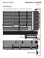
INSTALL GUIDE
600 Series Remote Vehicle Security System
WWW.ULTRASTARTERS.COM
Technical Support- 866.698.5872
FCC/ID Notice
This device complies with Part 15 of the FCC rules. Operation is subject to the following conditions:
(1) This device may not cause harmful interference, and
(2) This device must accept any interference received, including interference that may cause
undesired operation.
CAUTION: Changes or modifications not expressly approved by the part responsible for compliance
void the user’s authority to operate this devise.
INSTALL GUIDE
SECURITY SYSTEM
PAGE 2
Table of Contents
Table of Contents
Components
Page 2
600 Wiring Diagram
Page 3
Installation Tips
Pre-Installation Suggestions
Page 4
Installation Suggestions
Mounting The Module
Installing The LED
Installing The Program Button
Connecting The Starter Disable
Connecting The Dome Light Supervision
Under Hood Connections
Mounting The Siren
Page 4
Wire Connectors
14 Pin Main Harness Connector
4 Pin Red Connector- Keyless Entry
2 Pin Connector Red- Plug-in LED
2 Pin Blue Connector- Plug-in Program Button
3 Pin White Connector- Aux. outputs
4 Pin White Connector- Additional sensor input
Page 5
Installation
Basic Installation - Quick start
Shock Sensor Programming
Test The System
Page 6-7
Programming
Program Overview & System Reset
Program Menu 1 (User Settings)
Program Menu 2 (Alarm Settings)
Page 7-9
Operations
Single & Dual Car Operation
Transmitter Programming
Battery Replacement
Page 10
Other Features
System Service Mode
Service Mode- By remote
Page 11
Diagnostics
Page 12
Components
-Control module
- Remote transmitter(s)
- 14 pin main harness with
dual 30amp power inputs
- 4 pin Keyless Entry harness with
Driver’s Door Priority output
- Starter Disable harness
- Plug-in Valet Switch
- 4 pin Aux sensor harness
- Plug-in Led
- Multi-tone siren
- Installation and owner manuals
INSTALL GUIDE
SECURITY SYSTEM
PAGE 3
Wiring Diagram
Starter
Disable
Built-in Starter Disable relay (Normally Connected 87a & 30). See page. 5
500ma Output
Channel 4
Pink
Connect to (-) door pin
(-) Input
(-) Door Input
Green
Connect to hood pin
(-) Input
Hood Input
Blue
Connect to (+) door pin
(+) Input
(+) Door Input
Purple
Connect to Siren
3amp Output
(+) Siren
Brown
Connect to park lights
15amp Output
(+) Park Lights
White
See page. 4
(+.-) Input
Dome Light Relay
Blk/White
See page. 4
(+.-) Output
Dome Light Relay
Blk/White
(-) Output while armed
500ma Output
(-) When Armed
Orange
(-) Trunk Release Output
500ma Output
(-) Trunk Release
Connect to main Ignition
(+) Input
Ignition Input
Yellow
Connect to chassis ground
(-) Input
Ground
Black
12vt constant power
(+) Input
Main Power
Red
(-)500ma Output
Programmable - See menu 1, Setting 3
12vt inverter Output-Low Current
(+)500ma Output
Programmable - See menu 1, Setting 3
(-)500ma Output
Programmable - See menu 1, Setting 3
(-)500ma Output
Main Alarm Harness
Programmable - Menu 2
Grey
Door Lock Output
12vts Low Current
Door Unlock Output
Priority Output
Green
Red
Blue
Pink
4 PIN RED
- 2 PIN RED
LED
-
Valet Switch
2 PIN BLUE
SIDE VIEW
Negative Output When Disarmed
(-)500ma Output
Programmable - See menu 2, Setting 7
(-)500ma Output
Triggers when 12vt circuit is broken
(+)500ma Input
Negative trigger input
(-)500ma Input
Negative trigger input
(-)500ma Input
Sensor ground output
(-)500ma Output
Sensor power output
(+)500ma Output
(-) When Disarmed
Horn / Channel 5.
(+) Disconnect
Sensor
Sensor
Sensor
Sensor
Full - Warn
Pre - Warn
Ground
Power
Green
Pink
Blue
3 PIN WHITE
Blue
Green
Black
Red
4 PIN WHITE
**500ma outputs are low current and are designed to activate relays.
SATELLITE LINK PLUG
4 PIN WHITE
INSTALL GUIDE
SECURITY SYSTEM
PAGE 4
Recommended Pre-Installation Procedures
BEFORE STARTING INSTALLATION:
- Discuss the optional system features with the customer.
- Take a few minutes to review the installation and owners manuals.
- Do a walk around the vehicle and check for any damage.
- If installing a LED discuss the placement with customer before installing.
Recommended Installation Procedures
Mounting the Module
Never mount the module in the engine compartment. Select a location under the dash to install the
main module. Be certain that the module is securely attached and does not obstruct any
serviceable areas. Mount the module so that it cannot be seen if looking under the dash as it
could be easily unplugged by a thief. The module must be free from all moving parts such as
brake, clutch and gas pedals linkages.
Installing The Led
Choose a location that will be highly visible when the LED is installed. Most vehicles are equipped
with knock out panels in the dashboard, these panels are easily removable and can be easily
replaced if necessary. Once the location is picked, use a 5/16th drill bit and drill a hole through the
panel. Test fit the LED into the hole. If the hole was drilled to large, place the LED in the hole and
glue in place from the back of the panel. Plug the Led into the Red connector on the main module.
Installing The Program Button
Choose a location to mount the Program Button. This location should be hidden and not visible from
outside the vehicle. Once the location of the switch is picked, use a 1/4” drill bit and drill a hole.
Remove the nut and push the Program button through the hole. Replace the nut and tighten until
the switch is secure. Plug the valet into the Blue connector.
Connecting The Starter Disable
This system contains a built-in Starter disable relay. The brown starter kill wire from the wire
harness bag will connect to the module as normally connected. (87a & 30) Cut the brown wire in
half, then locate the vehicles starter wire. This wire will switch to 12volts in the crank or start
position only. Cut this wire in half and confirm that the vehicle will not start. Connect the brown
wires, one to each side of the cut starter wire. Route the brown wires to the main module and
connect.
Determine the door pin type. Positive, door pin wire switches to 12 volts when the door is opened.
Negative, door pin wire switches to ground when the door is opened. For positive door, connect one
of the black/white wires to 12volts and the other to the door pin wire. For negative connect one of the
black/white wires to ground and the other to the door pin wire.
Mounting The Siren
Choose a location in the engine compartment that is away from high heat sources and direct
exposer to water. The siren should be mounted as well as grounded to solid metal. Run the wiring
for the siren so that it can not be seen or reached from below the vehicle.
INSTALL GUIDE
SECURITY SYSTEM
PAGE 5
14 Pin Connector
Pink
Green
Blue
Purple
Brown
White
Blk/White
Blk/White
Orange
Grey
Yellow
Black
Red
Channel 4 Output
(-) Door Input
(-) Hood Input
(+) Door Input
(+) Siren Output
(+) Park lights
(+/-) Dome Light
(+/-) Dome Light
(-) When Armed
(-) Trunk Release
Ignition Input
Ground Input
Main Power Input
Programmable - See menu 2, setting 5.
Negative door pin switch input.
Negative input from hood pin switch.
Positive door pin switch input.
Positive output for siren.
Programmable - menu 2, setting 3.
Dome light supervision. See page 5.
Dome light supervision. See page 5.
Negative output when system is armed.
Positive trunk release. 500ma max.
Input from vehicles ignition wire.
System ground input.
Constant 12 Volt input.
4 Pin Connector Red
Green
Red
Blue
Pink
Door Lock
12 Volt Output
Door Unlock
Second Unlock
Programmable - menu 1, setting 3.
Output for voltage inverter. Low Current Only
Programmable - menu 1, setting 3.
Programmable - menu 1, setting 3
2 Pin Connector Blue
Plug-in Program Button Connector.
The program Button is used to access the systems Programming Menu’s.
See page 5. for installation instructions.
2 Pin Connector Red
Plug-in LED Connector.
See page 5. for installation instructions.
3 Pin Connector White
Green
Pink
Blue
(-) When Disarmed
Horn / Channel 5.
(+) Disconnect
Negative output when disarmed.
Programmable - See menu 2, setting 7
Triggers when 12volt circuit is broken.
4 Pin Connector White
Blue
Green
Black
Red
Sensor Full Warn
Sensor Pre Warn
Ground Output
12 Volt Output
Input trigger for addition alarm sensor(s)
Input trigger for addition alarm sensor(s)
Ground output for addition alarm sensor(s)
12 volt output for additional alarm sensor(s)
INSTALL GUIDE
SECURITY SYSTEM
PAGE 6
Quick Start Install
Step 1 - Connect All Of the Following Wires
14 Pin Power Connector
Black
Yellow
Red
White
Green*
Purple*
Ground Input
Ignition Input
MainPower Input
(+) Park lights
(-) Door Input
(+) Door Input
System ground input.
Input from vehicles ignition wire.
Positive output for siren.
Programmable - menu 2, setting 3.
Negative door pin switch input.
Positive door pin switch input.
*Test for door pin type (Positive or Negative) then connect the appropriate wire (Green or Purple)
Step 2- Plug-In The Module
When all the connections are done, the control module can be plugged in. Before connecting the
control module, make sure the ignition is in the OFF position. Plug in the 6 pin harness then the 14
pin followed by any other connectors that were used.
Step 3- Program, Test And Adjust The Shock Sensor
To program the Shock Sensor.
1.Press and release Lock button Five times.
2.The system will chirp and the park lights will flash three times then stay “ON”.
3.Within 10 seconds impact vehicle in a safe place (i.e. - Window pillar) with amount of force
wanted to activate alarm. The siren will chirp upon learning the impact.
4. The Shock Sensor is now programmed.
5. Press the Unlock button to exit the Program Mode.
To test the Shock Sensor.
1. Press the Lock button once to arm the system.
2. Wait five seconds then impact the vehicle. Lighter impacts to the vehicle should trigger the warn
away (The siren will chirp three times). A harder impact to the vehicle will trigger the full
alarm.(The siren will activate for 60 seconds then turn off).
3. To deactivate the alarm when triggered, press the unlock button twice.
To adjust the Shock Sensor.
1. Repeat the shock sensor learning.
- If the sensor was to sensitive, impact the vehicle with greater force.
- If the sensor was not sensitive enough, impact the vehicle with less force.
*For best results ensure that the Control Module is mounted securely to the vehicle.
Test The System
1. Open all the vehicles windows.
2. Press the Lock button to arm the system.
3. Wait five seconds (or until the dome light goes out) then reach in through a window and open
the door.
The alarm will then activate (repeat on all the doors).
4. Test the Shock Sensor again and adjust if necessary.
5. Insure that all additional features are working as intended.
6. If necessary proceed to Program Mode to adjust the programmable outputs.
Your Basic Install Is Complete!
SECURITY SYSTEM
INSTALL GUIDE
PAGE 7
Programming Overview
Program mode allows you to adjust the settings and options of your system.
Your system has been intelligently designed by installers with years of experience. The system’s
default settings do not require any program changes in most cases. However, this system does
incorporate a highly advanced programming system that includes 2 menus with numerous options
and settings that can be easily adjusted for custom installations and applications.
Entering Program Mode
To Enter Program Mode
1) Make sure ignition is in the off position.
2) Within three seconds turn the key ON - OFF - ON - OFF - ON. Leave Key ON.
3) Press and release the Program Button one time.
4) Park lights will come and the siren will chirp to confirm entering Program Mode.
5) Select Desired Program Menu by the following:
Press Button #1
Lock
User Options Page 8.
Press Button #2
Unlock
Alarm Settings Page 9.
6) The selected mode will be confirmed by a siren chirp and one park light flash.
7) The Program Menu may be changed at any time by pressing the transmitter buttons as
above, this allows the installer to change a setting from one menu, then quickly jump to
another menu and change another setting without exiting Program Mode.
8) Program Mode will be exited if there is no activity for 30 second or if the key is turned to the
“Off” position. This will be confirmed by one siren chirp and park light flash.
Note: If unit does not enter Program Mode, turn ignition off and repeat steps 1-4.
** The ignition wire(Yellow) MUST be connected to the vehicle’s ignition wire. If it is not
connected it will not be possible to enter the Program Modes.
Changing the Programmable Settings
To Select and Change A Program Setting:
1) Enter Program Mode.
2) Select the desired Program Menu. (See pages 8&9)
3) Press & release the Program Button the correct number of times to select the desired
Program Setting(as listed on pages (8&9). The park lights will flash and the siren will chirp to
indicate the current setting that is selected.
4) Press and hold the Program Button until the parking lights / siren confirm the selected setting.
The park lights will flash and the siren will chirp to indicate the option selected within the setting.
5) Turn the ignition key “Off” to exit Program Mode.
SYSTEM RESET
STEP 1 - Within three seconds turn the key ON-OFF-ON-OFF-ON (Leave the Key ON).
STEP 2 - Press and release the Program Button.
STEP 3 - Park Lights will come ON
STEP 4 - Press the Program Button a second time and hold for 8 seconds until the park lights
flash 3 times and siren chirps 3 times.
System is now re-set to factory defaults.
NOTE: Reset to defaults does not delete the transmitters from memory.
INSTALL GUIDE
SECURITY SYSTEM
PAGE 8
Menu 1 - User Settings
Setting 1- Ignition Auto Lock
1 Ignition Lock & Unlock Enabled
1 Light Flash
Doors Lock/Unlock when the key is turned On/Off
2 Ignition Lock Only
2 Light Flashes Doors Lock when ignition key is turned ON only
*3 Ignition Auto Lock Disabled
3 Light Flashes Doors do not Lock or Unlock with Ignition key
Press the Valet Switch 1 time to select setting 1 (This will be confirmed by 1 LED flashes)
Press and hold the Valet Switch until you receive the appropriate # of park light flashes and/or siren chirps.
Release the Valet Switch. Press the Valet momentarily to move to next program step or repeat to change selection.
Setting 2- Horn Honk Settings
1 Lock & Unlock chirps Disabled
2 Lock & Unlock chirps Enabled
*3 Chirps Enabled
1 Flash
2 Flashes
3 Flashes
A audible chirp for Panic Mode only
Chirp for Lock & Unlock but NO indication for Start
Chirp indication for Lock, Unlock and Start
Press the Valet Switch 2 times to select setting 2 (This will be confirmed by 2 LED flashes)
Press and hold the Valet Switch until you receive the appropriate # of park light flashes and/or siren chirps.
Release the Valet Switch. Press the Valet momentarily to move to next program step or repeat to change selection.
Setting 3- Door Lock Options
1 Double Pulse Unlock
2 3 Second Lock & Unlock
*3 0.75 Second Pulses
1 Flash
2 Flashes
3 Flashes
Single .75 second lock and double unlock pulse
3 second pulses for lock & unlock
0.75 second pulses for lock and unlock
Press the Valet Switch 3 times to select setting 3 (This will be confirmed by 3 LED flashes)
Press and hold the Valet Switch until you receive the appropriate # of park light flashes and/or siren chirps.
Release the Valet Switch. Press the Valet momentarily to move to next program step or repeat to change selection.
Setting 4 -Sensor - Enable / Disable
1 Sensors Disabled
* 2 Sensors Enabled
1 Flash
2 Flashes
Shock sensor and Aux. Sensor disabled
Shock Sensor and Aux. sensor enabled.
Press the Valet Switch 4 times to select setting 4 (This will be confirmed by 4 LED flashes)
Press and hold the Valet Switch until you receive the appropriate # of park light flashes and/or siren chirps.
Release the Valet Switch. Press the Valet momentarily to move to next program step or repeat to change selection.
Setting 5 - Passive / Active Arming
1 Passive Arming
2 Active Arming With Rearm
* 3 Active Arming
1 Flash
2 Flashes
3 Flashes
Auto Arms 30 seconds after last door is closed
Unlock is pressed and no door is within 30 sec.
Alarm arm by remote transmitter only.
Press the Valet Switch 5 times to select setting 5 (This will be confirmed by 5 LED flashes)
Press and hold the Valet Switch until you receive the appropriate # of park light flashes and/or siren chirps.
Release the Valet Switch. Press the Valet momentarily to move to next program step or repeat to change selection.
Setting 6 - Active / Passive Locks
1 Active Locking
*2 Passive Locks
1 Flash
2 Flashes
Doors do not auto-lock with passive arming
Doors Auto-Lock with passive arming.
Press the Valet Switch 6 times to select setting 6 (This will be confirmed by 6 LED flashes)
Press and hold the Valet Switch until you receive the appropriate # of park light flashes and/or siren chirps.
Release the Valet Switch. Press the Valet momentarily to move to next program step or repeat to change selection.
INSTALL GUIDE
SECURITY SYSTEM
PAGE 9
Menu 2- Alarm Settings
Setting 1 - Car Finder/ 5th Channel
1 Car Finder OFF
1 Light Flash
Car Finder Mode Disabled
*2 Car Finder ON
2 Light Flashes
Car Finder Mode Enabled
**To operate the 5th channel on button #4, setting 7 must be programmed for 5th channel output.
Press the Valet Switch 1 time to select setting 1 (This will be confirmed by 1 LED flashes)
Press and hold the Valet Switch until you receive the appropriate # of park light flashes and/or siren chirps.
Release the Valet Switch. Press the Valet momentarily to move to next program step or repeat to change selection.
Setting 2 - Secure Valet Mode
1 Secure Valet Active
1 Flash
Ignition “ON” and valet switch held for 15 seconds
2* Normal Valet Active
2 Flashes
Ignition “ON” and valet switch held for 5 seconds
Press the Valet Switch 2 times to select setting 2 (This will be confirmed by 2 LED flashes)
Press and hold the Valet Switch until you receive the appropriate # of park light flashes and/or siren chirps.
Release the Valet Switch. Press the Valet momentarily to move to next program step or repeat to change selection.
Setting 3 - Park Light Output
1 Parking Lights on Disarm
1 Flash
Park Lights on for 30 seconds on disarm
2 Negative Park Light
2 Flashes
Switches Park Light and the Trunk Release outputs
3* Normal Parking Lights
3 Flashes
2 Park Light Flashes on disarm
Press the Valet Switch 3 times to select setting 3 (This will be confirmed by 3 LED flashes)
Press and hold the Valet Switch until you receive the appropriate # of park light flashes and/or siren chirps.
Release the Valet Switch. Press the Valet momentarily to move to next program step or repeat to change selection.
Setting 4 - Horn Honk Timing
1 5ms Pulsed Output
1 Flash
Short (Quiet) Pulses
2 20ms Pulsed Output
2 Flashes
Long (Loud) Pulses
*3 10ms Pulsed Output
3 Flashes
Normal (Medium) Pulses
Press the Valet Switch 4 times to select setting 4 (This will be confirmed by 4 LED flashes)
Press and hold the Valet Switch until you receive the appropriate # of park light flashes and/or siren chirps.
Release the Valet Switch. Press the Valet momentarily to move to next program step or repeat to change selection.
Setting 5 - 4th Channel Settings
1 Pulsed Output
1 Flash
2 Latched Output
2 Flashes
*3 Active Output
3 Flashes
Pulsed for 0.75 seconds upon 4th Channel Activation
Latched until repeated or ignition “ON”
Active for as long as the button is held on Transmitter.
Press the lock and Star buttons together to activate the 4th Channel output.
The Shock Sensor and ignition will be bypassed upon 4th channel activation.
Press the Valet Switch 5 times to select setting 5 (This will be confirmed by 5 LED flashes)
Press and hold the Valet Switch until you receive the appropriate # of park light flashes and/or siren chirps.
Release the Valet Switch. Press the Valet momentarily to move to next program step or repeat to change selection.
Setting 6 - Car Jack Mode
1 Type 1
1 Flash
Press button #4 or open the door while the Ignition is “ON”
2 Type 2
2 Flashes
Press button #4 or by turning the Ignition “On”
*3 Car Jack OFF
3 Flashes
No Car Jack Functions
Press the Valet Switch 6 times to select setting 6 (This will be confirmed by 6 LED flashes)
Press and hold the Valet Switch until you receive the appropriate # of park light flashes and/or siren chirps.
Release the Valet Switch. Press the Valet momentarily to move to next program step or repeat to change selection.
Setting 7 - Horn/ 5th Channel
1 5th Channel
2 Horn Honk 2
*3 Horn Honk 1
1 Flash
2 Flashes
3 Flashes
Pulsed output when activated by button #4
Horn Honk Output - Full Alarm ONLY
Horn Honk with Arm & Disarm Chirps
INSTALL GUIDE
SECURITY SYSTEM
PAGE 10
First Car Operation
Press Once to Lock the doors and arm the alarm. Hold for Panic Mode.
Press a second time and hold for Constant Lock Output.
First Car
Press once to unlock the doors and disarm the alarm
Press and hold for the Trunk / Aux Output
Press this button to activate the 4th channel output.
This output can be used to activate additional alarm features.
Press once and hold for Car Finder
Press and release then hold to activate/deactivate Service Mode.
Second Car Operation (Optional)
2nd Car
then
&
&
&
then
=
=
=
=
Press Once to Lock and arm the alarm. Hold for Panic Mode.
Press a second time and hold for Constant Lock Output.
Press once to unlock the doors and disarm the alarm
Press and hold for the Trunk / Aux Output
Press this button to activate the 4th channel output.
This output can be used to activate additional alarm features.
Press once and hold for Car Finder
Press and release then hold to activate/deactivate Service Mode.
Transmitter Programming
Step 1 - Within three seconds turn the ignition ON-OFF-ON-OFF-ON - Leaving ON.
Step 2 - Press and hold the Program Switch - Parking Lights will come ON **if park-lights do not
come on at this point, turn key off for 5 seconds, then repeat step 1.
Step 3 - Continue to hold the Program Switch until park lights go out.
Step 4 - Press the LOCK button on each of 1st car remote’s and press the # button on Each of
the 2nd car remote’s of the transmitters to be programmed. The park lights will Flash
once and the siren will chirp once each time a new code is learned.
Note: Transmitter programming must done quickly. Do not pause more than one second between
each transmitter. All the transmitters to be used must be programmed at the same time.
All transmitters not programmed at this time will be erased from memory for security.
The system holds a maximum of 3 transmitter codes including 2nd car remote codes.
You can program the same remote as a 1st car remote in one vehicle and as a 2nd car
remote in a second vehicle.
Battery Replacement
The transmitter battery should be changed at least once every year to maintain proper operating
range. Replace with quality23A 12volt Alkaline battery.
Carefully remove
the screw from
back of the remote.
+
-
Remove top case
then replace the
battery.
Replace top case.
Re-install screw.
Test remote for
proper operation.
SECURITY SYSTEM
INSTALL GUIDE
PAGE 11
System Service Mode
ACTIVATING SERVICE MODE
1. While the ignition is “ON” press and hold the Program Button for five seconds.
The park lights will flash and the siren will chirp five times to confirm that the
system is in Service Mode.
2. While in Service Mode the remote start functions will be disabled and LEDs will
be “ON” steady. Door locks and trunk release are still operational.
DEACTIVATING SERVICE MODE
1. While the ignition is “ON” press and hold the Program Button for five seconds.
The park lights will flash and the siren will chirp two times to confirm that the
system has exited Service Mode.
2. Remote start functions will return to normal operation.
Service Mode- By Remote
SERVICE MODE ACTIVATED
1 - Press and release button 4 then hold Button 4 again for 6 seconds until
status LED comes on solid.
NOTE: The siren will chirp 5 times as confirmation.
SERVICE MODE DEACTIVATED
1 - Press and release button 4 then hold Button 4 again for 6 seconds until
status LED turns of.
NOTE: The siren will chirp 2 times as confirmation.
Anti Car Jacking Mode
Only program this feature if it specifically requested by the customer. Ensure that user is
fully trained on the operation of this feature. When car jack mode is activated the system
will no longer respond to the remote transmitters. If the starter disable feature was installed
the vehicle will not start.
When the Car Jack Mode is activated the system will start flashing the LED rapidly for five seconds.
The park lights and siren will then activate once every second for 10 seconds in Countdown Mode.
After 10 seconds the alarm will trigger into Full Alarm, the system will no longer respond to the
transmitters and the starter disable output will activate to disable the vehicle from starting.
ACTIVATING CAR JACK MODE
Program Menu 2, Setting 5
- Type 1- Car Jack Mode will activate if the door is opened while the ignition key is in the “On” position.
Car Jack Mode may also be activated by pressing the # button on the remote transmitter
while the ignition key is in the “On” position.
- Type 2- Car Jack Mode will activate if the ignition key is turned to the “On” position. Car Jack Mode
may also be activated by pressing the # button on the remote transmitter while the ignition
key is in the “On” position.
DEACTIVATING CAR JACK MODE
1.During the Countdown Mode - Turn the ignition key “ON” then press and release the
Program Button one time.
2.After Full Alarm - Turn the ignition key “Off” then “ON” then press and hold the Program
Button until the alarm turns off. (About Eight seconds)
INSTALL GUIDE
SECURITY SYSTEM
PAGE 12
Diagnostics
Alarm Diagnostics
If the alarm system is triggered while armed, the system will retain in memory the cause of the
trigger. The diagnostics can then be used to determine what the cause of the trigger was. When
disarming the alarm, the siren/horn will chirp 3 times instead of the usual 2 times to indicate the
alarm had been triggered.
The system’s LED will also flash in pulses to indicate which input triggered the alarm.
NOTE: LED status will be cleared when ignition is turned ON. For proper memory clearing, insure
to connect the ignition input to the ignition on the vehicle.
Diagnostics Chart
Park Light Flashes
LED Flashes
Diagnostic
Two Flashes
Three Flashes
Four Flashes
Five Flashes
None
None
None
None
On/Off
Two Flashes
Three Flashes
Four Flashes
Five Flashes
Off
On Solid
Single Flashes
Rapid Flashes
Rapid Flashes
Shock Sensor Triggered
Door Input Triggered
Ignition Input Triggered
Hood Input Triggered
System Disarmed
Valet/Service Mode
System Armed
Passive Arming
Car Jack Mode
Additional LED Flashes