1
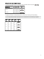
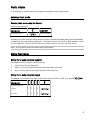
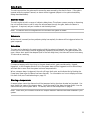
ENGLISH ..................................................................................................................................... 2
The Energizer Monitor Unit.............................................................................................................2
Arming and Disarming the Electric Fence Security System................................................................4
Daytime Fence Monitoring ..............................................................................................................6
Alarm Response ..............................................................................................................................8
Panic Alarm ....................................................................................................................................9
System Operation .........................................................................................................................10
Setting the User and Owner PIN numbers .....................................................................................12
Troubleshooting ...........................................................................................................................13
Care and Maintenance ..................................................................................................................14
Electric Fence Safety Considerations ..............................................................................................15
Warranty ......................................................................................................................................17
© Tru-Test Limited, 2003-2005. All rights reserved.
Tru-Test, Compact and Premium are trademarks of Tru-Test Corporation Limited.
No part of this publication may be photocopied, reproduced, stored in a retrieval system, or transmitted in any form or by any
means, electronic, mechanical, photocopying, recording or otherwise without the prior written permission of Tru-Test Limited.
Product specifications may change without prior notice.
For more information about the Tru-Test range of quality products, see www.tru-test.com.
Tru-Test Limited
25 Carbine Road
Mt Wellington
Auckland 1006
New Zealand
807753 Issue 1 11/05
Postal address:
P O Box 51078
Pakuranga
Auckland 1730
New Zealand
ENGLISH
The Energizer Monitor Unit
Congratulations on your recent purchase of an Energizer Monitor Unit electric fence security
system.
The unit is a combined electric fence energizer and alarm system designed primarily for security
fencing applications. When armed, the unit continuously checks the fence voltage and triggers an
alarm if the fence voltage falls outside of preset limits (e.g. when an intruder attempts to breach or
climb the fence).
The system can provide a high level of security to a wide range of installations, and includes the
following features:
•
•
•
•
•
•
•
•
•
•
•
•
•
•
•
Easy to use.
Powerful electric fence energizer with up to 4 joules output energy.
Adjustable fence voltage up to 12,000 volts.
Reduced false alarms, due to a unique dynamic fence monitoring option that distinguishes
sudden fence voltage changes from slow changes caused by environmental degradation.
Provision for up to four Keypads and/or Keyswitches (altogether).
Full gate access control using low voltage cabling for improved system reliability.
Outputs for auxiliary warning equipment, and a siren up to 15 W.
Easy connection to a tele-dialler or your master alarm system.
An internal battery keeps the unit working during a power failure.
Compatible with solar power installations.
‘Flash’ computer memory allows easy on-site software upgrades.
Flashing lamp warnings of poor battery and loss of mains power.
Low voltage isolated mains power pack for improved safety.
Many system configuration option settings available for maximum flexibility.
Built-in fault diagnostics for efficient servicing.
Getting Started
The unit has a set of configuration options that can be set using a Keypad. These are usually set by
the installer, but may be re-configured later if required.
2
Which Energizer Monitor Unit do you have?
The electric fence security system is based on one of two units, a Premium or a Compact:
Premium
A Premium unit has just a single ‘power’ indicator lamp on the case front. This unit is typically
installed together with a Keypad and/or Keyswitch.
Compact
A Compact unit has a Keyswitch mounted on the case front and a full set of indicator lamps (these
allow the unit to be installed on its own, without a Keypad or Keyswitch).
It has the same full range of features and customisable settings as provided on the Premium, but
these are set by your installer at the time of installation. The settings may be reconfigured later by
your installer.
Explanation of symbols on your unit
Read full instructions before use.
Class III appliance in which protection against electric shock relies on supply at safety extralow voltage (SELV) and in which voltages higher than those of safety extra-low voltage are
not generated.
3
Arming and Disarming the Electric Fence Security System
Arming the electric fence security system
Arm the system when you wish to fully secure the property. Arming the unit will electrify the fence
and enable gate and fence monitoring. The Keyswitch or Keypad can be used to arm the system:
Arming using the Keyswitch
Arming the system using the Keyswitch is easy:
1
2
3
Insert the key into the Keyswitch
Rotate ¼ turn to the right until a fast beeping is heard.
Return the key back to the upright position and remove.
Arming using the Keypad
Commands on the Keypad require a four digit User or Owner Personal Identification Number (UPIN
or OPIN) to be entered prior to a command sequence. The factory default UPIN is 1234, and the
factory default OPIN is 5555.
The Keypad will give a short beep to confirm each key press, a long high-pitched beep after each
successful command sequence, and a long low pitched beep after an invalid command sequence.
To arm the system, enter the UPIN or OPIN, then press ARM:
KEY
KEY
KEY
KEY
U
P
I
N
O
P
I
N
1 2 3 4
COMMAND
KEY
5
Arm using
User PIN
or
Owner PIN
For example, to arm the system with the factory default UPIN, the key sequence would be:
KEY
KEY
1 2 3 4
5
KEY
1
KEY
2
KEY
3
4
The system will arm. The Armed lamp will come on and the Pulse lamp will flash (provided the
fence is fault-free).
If the Armed lamp flashes and a slow beeping sound is heard, then the system has been configured
with a gate override exit delay. This gate override allows you to exit the secure area through the
gate without activating the alarm. After the delay period (for example, 2 minutes), the Armed
lamp will remain on and the beeping will stop.
4
Disarming the electric fence security system
Disarming using the Keyswitch
Disarm the system in the same way as you arm it.
1
2
3
Insert the key into the Keyswitch.
Rotate ¼ turn to the right until a fast beeping is heard.
Return the key back to the upright position and remove.
Disarming using the Keypad
To disarm the system, enter the UPIN or OPIN, then press
COMMAND
KEY
KEY
KEY
KEY
U
P
I
N
O
P
I
N
1 2 3 4
:
KEY
5
Disarm using
User PIN
or
Owner PIN
The system will disarm and return to Standby mode. The Armed lamp will turn off and the Pulse
lamp will stop flashing.
5
Daytime Fence Monitoring
Twenty-four hour fence monitoring can be provided by the unit, even without fully energizing the
fence. During the daytime, when people and children are expected to be around the fenced area,
fence monitoring can be provided at a reduced voltage, by selecting “Monitor mode”. In this
mode the unit is still able to monitor the electric fence installation, and will trigger the alarm if
someone tampers with it.
Entering Monitor mode
Entering Monitor mode using the Keypad
To set Monitor mode, enter the UPIN or OPIN, then press
COMMAND
KEY
KEY
KEY
KEY
U
P
I
N
O
P
I
N
1 2 3 4
:
KEY
5
Monitor using:
User PIN
or
Owner PIN
Note that in Monitor mode the gate is not alarmed, but the Keypad will chime each time the gate
is opened to announce the presence of a visitor or intruder.
Note: This feature cannot be activated using the Keyswitch.
Exiting Monitor mode
Exiting Monitor mode using the Keyswitch
The Keyswitch can be used to exit Monitor mode.
1
2
3
6
Insert the key into the Keyswitch
Rotate ¼ turn to the right until a fast beeping is heard.
Return the key back to the upright position and remove.
Exiting Monitor mode using the Keypad
To exit Monitor mode and return to Standby, enter the UPIN or OPIN, then press
KEY
KEY
KEY
KEY
U
P
I
N
O
P
I
N
1 2 3 4
COMMAND
:
KEY
5
Return to Standby using:
User PIN
or
Owner PIN
The system will disarm, the Armed lamp will turn off and the Pulse lamp will stop flashing.
Tip: You may instantly activate Armed and Monitor modes without first disarming the system.
KEY
KEY
U
P
1
2
KEY
KEY
I
N
3
4
KEY
5
Ú
U
P
I
N
or
O
P
I
N
Ú
O
P
I
N
7
Alarm Response
If the electric fence security system is breached, it triggers an alarm — the security siren and any
auxiliary equipment, such as a master alarm system/tele-dialler, are activated.
After activation, the cause of the alarm is indicated by the Fence and Gate lamps (on the case front
of the Compact, the Keypad, and Keyswitch). Whenever the cause of alarm is present, the
appropriate lamp will also flash.
After a programmed period (say, 3 minutes) the siren is automatically switched off, but any
auxiliary equipment remains activated until the system is disarmed.
After the alarm siren has switched off automatically, the electric fence security system will remain
active and be ready to raise the alarm again if necessary. Each subsequent activation of the alarm
will normally cause the siren to be re-triggered.
The siren can be silenced immediately by the user, without deactivating the electric fence security
system. This can be done using the Keyswitch or Keypad.
Silencing the siren and turning off auxiliary equipment
Silencing the siren and turning off auxiliary equipment using the Keyswitch
First silence the siren:
1
Insert the key into the Keyswitch.
2
Rotate ¼ turn to the right until a fast beeping is heard.
3
Return the key back to the upright position and remove.
Then disarm the unit and deactivate auxiliary equipment:
•
Repeat steps 1-3.
Silencing the siren and turning off auxiliary equipment using the Keypad
First silence the siren:
•
Enter the UPIN or OPIN, then press
COMMAND
KEY
KEY
KEY
KEY
U
P
I
N
O
P
I
N
1 2 3 4
:
KEY
5
Silence using
User PIN
or
Owner PIN
Then disarm the unit and deactivate auxiliary equipment:
•
8
Repeat the step above.
Panic Alarm
In an emergency, a panic alarm can be raised manually by entering Panic mode.
Entering Panic mode
Entering Panic mode using the Keypad
Enter the key sequence:
KEY
1
COMMAND
COMMENT
Entering Panic mode
Hold for 3 seconds
Activating the alarm manually using the panic button overrides all system settings and immediately
activates the siren and auxiliary equipment. The electric fence is turned off to allow people to come
to your assistance. The siren will not time-out and will continue until you exit Panic mode.
Note: A panic alarm cannot be raised using the Keyswitch.
Exiting Panic mode
Exiting Panic mode using the Keyswitch
The Keyswitch can be used to exit Panic mode:
1
2
3
Insert the key into the Keyswitch.
Rotate ¼ turn to the right and leave until a fast beeping is heard.
Return the key back to the upright position and remove key.
Exiting Panic mode using the Keypad
The Keypad can be used to exit Panic mode by entering the UPIN or OPIN, then press
COMMAND
KEY
KEY
KEY
KEY
U
P
I
N
O
P
I
N
1 2 3 4
:
KEY
5
Exit Panic mode using:
User PIN
or
Owner PIN
9
System Operation
Indicator lamps
You can quickly check the operating status of the electric fence security system by viewing the LED
indicator lamps, fitted to Keyswitch, Keypad and the case front of the Compact unit.
Lamp
*
State
Indicates
Off
When armed, indicates the fence is damaged or security has been
breached
Flashing
The unit has delivered a good fence pulse
Off
Disarmed (Standby mode)
Slow Flashing
Armed but waiting for entry/exit delay to time out
Flashing
Monitor mode (low power daytime operation)
Fast Flashing
Tampering detected
On
Armed
Off
Mains power off and battery disconnected or flat
Slow Flashing
Mains power off and battery good
Fast Flashing
Fault logged (Seek the advice of your installer.)
On
Mains power on and battery good
Off
Normal operation—if armed, system is secure
Flashing
Fence alarm condition present
On
Fence currently secure, but the fence alarm has previously been
triggered
Off
Gate closed
Flashing
Gate open
On
Gate currently closed, but the gate alarm has been triggered
Off
Normal operation
Flashing
Panic alarm has been activated.
*A panic indicator lamp is not fitted to Compact unit or the Keyswitch (fitted to the Keypad only).
Notes:
- If the battery is discharged and there is no mains power, the unit automatically switches to
Sleep mode and all indicator lamps turn off to conserve battery life. In addition, the Keypad
and Keyswitch beep every 10 seconds.
- To resume normal operation, charge the battery for a day (connect mains power) before rearming the system. If the system still does not function correctly, seek the assistance of your
installer.
10
Gate Alarm
The unit can monitor the gate used to access the area secured by the electric fence. If the gate is
opened while the system is armed, an alarm will be triggered (subject to the optional exit/entry
delays described below).
Exit/entry delays
The unit can be set with a range of exit/entry delay times. This allows a person arming or disarming
the unit sufficient time to exit or enter the secured area through the gate, before the alarm is
triggered. If required, ask your installer to set the delay times.
Note: The electric fence is energized from the moment the system is armed.
Gate alarm
While the unit is armed (and any exit/entry delay has expired), the alarm will be triggered when the
gate is opened.
Gate chime
The user can be alerted to the gate opening while the system is disarmed, via a gate chime. The
chime is a two-tone beep from the Keypad and Keyswitch (where fitted). If the gate has been left
open, after a short period has elapsed (half of the exit delay time), the chime will sound once every
10 seconds as a warning.
Tamper alarm
If someone tampers with the wiring to the gate break-switch, gate override switch, Keypad,
Keyswitch, or the Energizer Monitor Unit, the system alarm will be triggered and the Armed lamp
will flash fast to warn that the system has been tampered with.
When a tamper alarm is triggered, the unit will log a fault code, and indicate this by flashing the
Power lamp (even after the alarm has been silenced). For information on how to display and clear
this fault code, see Troubleshooting on page 13.
Silencing a tamper alarm
A tamper alarm cannot be silenced until the tampered wiring has been located and repaired. You
must rectify the cause of the tamper alarm. Once the cause of the alarm has been fixed, it can be
silenced like any other system alarm. For details, refer to Alarm Response on page 8.
2
Note: Check with your installer to see which tamper detection features have been enabled in your
system.
11
Setting the User and Owner PIN numbers
On Keypad equipped systems, the User PIN (UPIN) or Owner PIN (OPIN) number must be entered
before the unit will obey any commands, except when raising a panic alarm. These numbers should
be kept secret to prevent unauthorised operation of the unit.
Until configured, the factory default value of the OPIN is 5555, and the UPIN is 1234. New PIN
numbers should be chosen and set for the UPIN and OPIN as soon as possible after the system is
installed (if your system is fitted with a Keypad), to prevent unauthorised access.
The UPIN and OPIN differ only in that the OPIN is required to change these PIN numbers, whereas
the UPIN cannot do this, even for the UPIN itself.
Setting the UPIN
To set the UPIN, enter the current OPIN followed by the command
, and then
key in the new UPIN twice, followed by
, as shown in the sequence below:
KEY
KEY
KEY
KEY
Current UPIN
U
P
I
N
New UPIN
U
P
I
N
New UPIN
U
P
I
N
COMMAND
1 2 3 4
KEY
5
KEY
6
KEY
7
Setting the UPIN:
Setting the OPIN
To set the OPIN, enter the current OPIN followed by the command
and then
twice key in the new OPIN followed by
, as shown in the ordered sequence below:
KEY
KEY
KEY
KEY
1 2 3 4
5
6
7
KEY
COMMAND
KEY
KEY
Setting the OPIN:
Current OPIN
O
P
I
N
New OPIN
O
P
I
N
New OPIN
O
P
I
N
Resetting the OPIN
If you should ever lose the OPIN, you will need to consult your installer to have the OPIN reset to
the factory default value.
12
Troubleshooting
General system faults
If you encounter a problem with your electric fence security system, first ask your service agent for
advice.
If the unit detects a fault in the system, it will log a fault code, and the Power lamp will start
flashing fast. Additionally the beeper will sound in the Keyswitch and Keypad. Ask your service
agent for assistance.
If the supply cord is damaged it must only be replaced by your service agent, in order to avoid a
hazard.
Keypad or Keyswitch faults
In rare instances, the Keypad or Keyswitch may stop functioning normally (maybe after a bad
lightning storm). In this instance, the Keypad or Keyswitch needs to be reset. Ask your service
agent for assistance.
13
Care and Maintenance
While the electric fence security system has been designed to be as maintenance-free as possible,
observing the recommendations below will help to ensure a long and trouble-free life from your
system:
Have the internal battery in the Energizer Monitor Unit checked at least every two years by
your service agent, to preserve the back-up time of the unit.
Do not allow the Energizer Monitor Unit to go without mains power for long periods of time.
This will damage the internal back-up battery.
If you plan to disconnect mains power for more than a couple of days, disarm the Energizer
Monitor Unit and leave on standby, or have the battery disconnected by your service agent.
Do not leave the battery disconnected for over a month without charging.
If you know that mains power has been inadvertently removed for several days (especially if
the Energizer Monitor Unit was armed), have the battery checked by your service agent.
If any physical damage occurs to the electric fence security system (especially the outside
cables), have it checked and repaired promptly by your service agent, to ensure system
integrity.
The Power Pack supply cord cannot be replaced. If the cord is damaged, the whole Power
Pack should be replaced.
Ensure that the Power Pack is located indoors and protected against damage from physical
abuse, liquids, or corrosive chemicals. Have any suspected damage checked promptly by your
service agent for continued safety.
Do not disassemble the electric fence security system. There are no user serviceable parts
inside any of the Energizer Monitor Unit system components.
Ensure that the Energizer Monitor Unit and its accessories are always operated in a cool, dry,
well ventilated area.
Keep the Energizer Monitor Unit out of reach of children.
Should the outside of any system component require cleaning, disarm the system first for
safety. Then wipe gently with a soft cloth dampened in a mild soap-and-water solution. Do
not use harsh chemicals or cleaning solvents.
If the electric fence security system is to be decommissioned, return the Energizer Monitor
Unit to your installer for safe disposal.
•
•
•
•
•
•
•
•
•
•
•
•
•
Warning: Never open the Energizer Monitor Unit yourself, even for cleaning. Energizer
Monitor Units are sealed against dust and do not need cleaning inside.
14
Electric Fence Safety Considerations
If you are unsure of the meaning of the safety points detailed below, please seek clarification from
your installer before using the system.
The following section has been prepared from information appearing in international safety
standard IEC 60335-2-76. Please read it thoroughly.
Safety requirements
•
•
•
•
•
•
This product has been designed for use with electric security fences.
The Energizer Monitor Unit is suitable for indoor use only.
The Energizer Monitor Unit uses a sealed lead-acid rechargeable battery of 7 Ah capacity. Do
not use non-rechargeable batteries.
Do not attempt to replace the battery. Batteries should be replaced only by a suitably
qualified installer.
When disposing of the Energizer Monitor Unit, have the battery removed by your installer for
safe disposal. Do not dispose of the battery in a land-fill. Do not dispose in a fire.
In the event of a spill or leakage from the battery:
- Contain small spills with dry sand, earth and vermiculite. Do not use combustible materials.
If possible, carefully neutralise spilled electrolyte with soda ash, sodium bicarbonate, lime, etc.
- Wear acid-resistant clothing, boots, gloves and a face shield.
- Do not let un-neutralised acid get into the sewage system.
- Neutralised acid must be managed in accordance with approved local requirements.
Consult your local environmental agency.
Instructions for installation and connection of electric fences
Requirements for electric security fences
•
Electric security fences and their ancillary equipment shall be installed, operated and maintained in a
manner that minimizes danger to persons, and reduces the risk of persons receiving an electric shock unless
they attempt to penetrate the physical barrier, or are in the secure area without authority.
•
•
Electric security fence constructions that are likely to lead to the entanglement of persons shall be avoided.
Gates in electric security fences shall be capable of being opened without the person receiving an electric
shock.
•
An electric security fence shall not be supplied from two separate energizers or from independent fence
circuits of the same energizer.
•
For any two separate electric security fences, each supplied from a separate energizer independently timed,
the distance between the wires of the two electric security fences shall be at least 2.5 m. If this gap is to be
closed, this shall be effected by means of electrically non-conductive material or an isolated metal barrier.
•
•
•
Barbed wire or razor wire shall not be electrified by an energizer.
•
•
Follow the energizer manufacturer’s recommendations regarding earthing.
The distance between any electric security fence earth electrode and other earth systems shall be not less
than 2 m, except when associated with a graded earth mat.
NOTE: Where possible the distance between any electric security fence earth electrode and other earth
systems should preferably be at least 10 m.
Exposed conductive parts of the physical barrier shall be effectively earthed.
Where an electric security fence passes below bare power line conductors, the highest metallic element
shall be effectively earthed for a distance of not less than 5 m on either side of the crossing point.
15
•
Connecting leads that are run inside buildings shall be effectively insulated from the earthed structural parts
of the building. This may be achieved by using insulated high voltage cable.
•
Connecting leads that are run underground shall be run in conduit of insulating material or else insulated
high voltage cable shall be used. Care must be taken to avoid damage to the connecting leads due to the
effects of vehicle wheels sinking into the ground.
•
Connecting leads shall not be installed in the same conduit as the mains supply wiring, communication
cables or data cables.
•
Connecting leads and electric security fence wires shall not cross above overhead power or communication
lines.
•
Crossings with overhead power lines shall be avoided wherever possible. If such a crossing cannot be
avoided it shall be made underneath the power line and as nearly as possible at right angles to it.
•
If connecting leads and electric security fence wires are installed near an overhead power line, the
clearances shall not be less than those shown in the table below.
Minimum clearances from power lines for electric security fences
Power line voltage (V)
Clearance (m)
≤1 000
3
>1 000
>33 000
and ≤33 000
4
8
•
If connecting leads and electric security fence wires are installed near an overhead power line, their height
above the ground shall not exceed 3 m
•
This height applies to either side of the orthogonal projection of the outermost conductors of the power
line on the ground surface, for a distance of:
- 2 m for power lines operating at a nominal voltage not exceeding 1 000 V
- 15 m for power lines operating at a nominal voltage exceeding 1 000 V.
•
A spacing of 2.5 m shall be maintained between uninsulated electric security fence conductors or
uninsulated connecting leads supplied from separate energizers. This spacing may be less where conductors
or connecting leads are covered by insulating sleeving, or consist of insulated cables rated to at least 10 kV.
•
This requirement need not apply where the separately energized conductors are separated by a physical
barrier that does not have any openings greater than 50 mm.
•
A vertical separation of not less than 2 m shall be maintained between pulsed conductors fed from separate
energizers.
•
•
•
•
Electric security fences shall be identified by prominently placed warning signs.
The warning signs shall be legible from the secure area and the public access area.
Each side of the electric security fence shall have at least one warning sign.
Warning signs shall be placed:
- at each gate;
- at each access point;
- at intervals not exceeding 10 m;
- adjacent to each sign relating to chemical hazards for the information of the emergency services.
•
Any part of an electric security fence that is installed along a public road or pathway shall be identified at
frequent intervals by warning signs securely fastened to the fence posts or firmly clamped to the fence
wires.
•
•
The size of the warning sign shall be at least 100 mm × 200 mm.
•
16
The background colour of both sides of the warning sign shall be yellow. The inscription on the sign shall
be black and shall be either:
- the symbol of Figure 1, or
- the substance of “CAUTION: Electric security fence”.
The inscription shall be indelible, inscribed on both sides of the warning sign and have a height of at least
25 mm.
•
Ensure that all mains operated, ancillary equipment connected to the electric security fence circuit provides
a degree of isolation between the fence circuit and the supply mains equivalent to that provided by the
energizer.
NOTE: Ancillary equipment that complies with the requirements relating to isolation between the fence
circuit and the supply mains in Clauses 14, 16 and 29 of the standard for the electric fence energizer is
considered to provide an adequate level of isolation.
•
Mains supply wiring shall not be installed in the same conduit as signalling leads associated with the electric
security fence installation.
•
Protection from the weather shall be provided for the ancillary equipment unless this equipment is certified
by the manufacturer as being suitable for use outdoors, and is of a type with a minimum degree of
protection IPX4.
Figure 1 – Symbol for warning sign
Warranty
This product is warranted against faulty material and workmanship for a period from the date of
purchase. If a warranted defect occurs, return this product with proof of purchase to the place of
purchase. Details of warranty periods and other terms applying are available at the place of
purchase or at www.tru-test.com.
Note:
- No responsibility is accepted for any accident or damage caused subsequent to any tampering
with or modification to or misuse of this product, including (but not limited to) alterations
made by anyone other than Tru-Test or its agents.
- To the maximum extent permitted by law, this warranty is exclusive, personal to you and in lieu
of all other warranties, representations or conditions relating to this product (whether express
or implied and whenever arising) whether originating by statute, law, trade, custom or
otherwise.
17