1
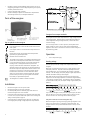
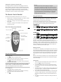
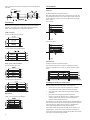
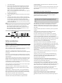
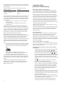
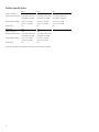
U S E R
M A N U A L
20, 36, 63 J Mains Energizer
Contents
Electric fencing and your energizer
Electric fencing and your energizer........................................................ 1
Parts of the energizer ........................................................................... 2
Installation ........................................................................................... 2
Operation ............................................................................................ 2
The Remote Control Handset ................................................................ 3
Communication between the energizer and a Remote Control Handset . 4
Building a permanent electric fence ...................................................... 5
Safety considerations............................................................................ 7
Frequently asked questions/Troubleshooting ......................................... 8
Servicing .............................................................................................. 9
Product specifications ......................................................................... 10
Congratulations on the purchase of your energizer. This product has
been constructed using the latest technology and construction
techniques. It has been engineered to give superior performance and
many years of service.
It is important to read these instructions carefully and thoroughly. They
contain important safety information and will assist you in ensuring that
your electric fencing system gives maximum performance and reliability.
Warning!
- USA and Canada - To reduce the risk of electric shock, the
energizer has a polarised plug (one blade is wider than the other).
This plug will fit in a polarised outlet one way. If the plug does not
fit fully in the outlet, reverse the plug. If it still does not fit, contact
a qualified electrician to install the proper outlet. Do not change
the plug in any way.
- Switch the energizer off before installation or performing any work
on the fence.
- Read all the safety considerations carefully. See Safety
Considerations on page 7.
- Check your installation to ensure that it complies with all local
safety regulations.
- The energizer must be located in a shelter, and the cable must not
be handled when the temperature is below 5 °C.
- Do not connect simultaneously to a fence and to any other device
such as a cattle trainer or a poultry trainer. Otherwise, lightning
striking your fence will be conducted to all other devices.
© 2003-2010 Tru-Test Limited
All product names and brand names in this document are trademarks or registered trademarks of their
respective holders.
No part of this publication may be photocopied, reproduced, stored in a retrieval system, or transmitted in
any form or by any means, electronic, mechanical, photocopying, recording or otherwise without the prior
written permission of Tru-Test Limited. Product specifications may change without prior notice.
For more information on other quality Tru-Test Group brands and products, visit www.tru-test.com.
Tru-Test Limited
25 Carbine Road
Mt Wellington
Auckland 1060
New Zealand
Postal address:
P O Box 51078
Pakuranga
Manukau 2140
New Zealand
815040 Issue 1 05/2010
Tru-Test Ltd thanks the International Electrotechnical Commission (IEC) for permission to reproduce
Information from its International Publication 60335-2-76 ed.2.0 (2002). All such extracts are copyright of
IEC, Geneva, Switzerland. All rights reserved. Further information on the IEC is available from www.iec.ch.
IEC has no responsibility for the placement and context in which the extracts and contents are reproduced
by the author, nor is IEC in any way responsible for the other content or accuracy therein.
Note:
-
This product has been designed for use with electric animal fences.
Keep this manual in a handy location.
Which energizer do I have?
Warranty
This user manual covers several models of energizer:
This product is warranted against faulty material and workmanship for a period
from the date of purchase. If a warranted defect occurs, return this product with
proof of purchase to the place of purchase. Details of warranty periods and other
terms applying are available at the place of purchase or at www.tru-test.com.
20 J model
820R / 20000R / M20R
820RE / 20000RE / M20RE*
36 J model
835R / 36000R / M36R
835RE / 36000RE / M36RE*
Note:
63 J model
63000R / M63R
-
-
No responsibility is accepted for any accident or damage caused subsequent
to any tampering with or modification to or misuse of this product,
including (but not limited to) alterations made by anyone other than
Tru-Test Group or its agents.
To the maximum extent permitted by law, this warranty is exclusive,
personal to you and in lieu of all other warranties, representations or
conditions relating to this product (whether express or implied and
whenever arising) whether originating by statute, law, trade, custom or
otherwise.
*These energizers are the European variants of the R energizers.
How does an electric fence work?
An electric fence system comprises an energizer and an insulated fence.
The energizer puts very short pulses of electricity onto the fence line.
These pulses have a high voltage, but are of very short duration (less
than 3/10,000ths of a second). However, a shock from an electric fence
pulse is very uncomfortable and animals quickly learn to respect electric
fences. An electric fence is not only a physical barrier, but is also a
strong psychological barrier.
What are the benefits of an electric fence?
An electric fence has many benefits over conventional fencing:
•
Requires less labour and materials to construct.
1
•
•
•
Flexibility to change or add paddocks when required. The use of
strip grazing techniques can allow temporary fencing to be quickly
and easily erected or removed.
Controls a broader range of animals.
Minimises damage to expensive livestock when compared with
other fencing mechanisms, for example barbed wire.
Parts of the energizer
Energizer fence output terminals
Key to symbols on the energizer
Fence earth terminal. Connect the fence earth terminal to the
earth system.
Fence output terminal. Connect the fence output terminal to
the fence.
Risk of electric shock! This energizer should be opened or
repaired only by qualified personnel.
Read full instructions before use.
This symbol on the product or its packaging indicates that this
product must not be disposed of with other waste. Instead, it
is your responsibility to dispose of your waste equipment by
handing it over to a designated collection point for the
recycling of waste electrical and electronic equipment. The
separate collection and recycling of your waste equipment at
the time of disposal will help conserve natural resources and
ensure that it is recycled in a manner that protects human
health and the environment. For more information about
where you can drop off your waste equipment for recycling,
please contact your local city recycling office or the dealer
from whom you purchased the product.
The energizer has a double-insulated construction.
Installation
•
•
•
•
•
2
Mount the energizer close to a power outlet.
Mount the energizer out of reach of children.
Use the template printed on the back page of this manual to
mount the energizer onto a wall or beam.
Connect the Fence earth terminal to a separate earth system that
is at least 10 m (33’) from other earth systems. See Installing and
testing an earth system on page 6.
Connect the Fence output terminal to the fence. Use either the
low voltage (yellow) or high voltage (red) fence output terminal.
The energizer has two Fence output terminals – high voltage (red) and
low voltage (yellow). Although the low voltage terminal produces a
lower voltage than the high voltage terminal, it delivers the same
amount of energy.
The low voltage terminal is used in dry areas, where sparks from a
higher voltage may cause a fire, or when special fire department
regulations are in force. This terminal can also be used to configure a
bi-polar fencing system.
Operation
•
Turn on the power supply.
Reading voltage
The LED display shows the voltage at the output terminals of the
energizer.
When first connected to the power source, all light segments on the
LED display illuminate. They then illuminate separately from left to
right and back again. This indicates that the energizer is operating
normally. The LED display, then, briefly displays a light sequence that
identifies the address setting of the energizer.
After three seconds, the energizer starts pulsing. Each of the light
segments on the LED display represent an increment of approximately
1 kV (1000 V) of output voltage. For example, if the first 4 segments
are illuminated at each pulse, the output voltage is approximately 4 kV
(4000 V).
If you see only red lights at each pulse and no green lights, this means
that your fence line is very heavily loaded, and you need to look for
faults on the fence line. See Using the fault finder on page 3.
Full-power mode (36 J and 63 J energizers only)
While the energizer is pulsing, if the large, green light segment on the
right is lit up continuously, it is operating in full-power mode. The
energizer switches to full-power mode when there is a heavy load on
the fence.
Output power control (63 J energizers only)
The energizer optimises the delivery of output energy to match the
fence conditions. For example, if there is a sudden heavy load on the
fence (e.g. during heavy rain, or if there are one or more short circuits
on the fence), the energizer will progressively increase the output
energy in order to maintain the fence voltage. If the load is removed,
the energizer re-adjusts the output energy accordingly.
The Remote Control Handset
The Remote Control Handset is three tools in one. It acts as a:
•
•
•
Remote control – Switching the energizer on or off from a remote
location anywhere on the electric fence system
Fault finder – Assisting in the location of faults anywhere on the
fence system
Volt meter – Providing instant feedback on fence performance
(voltage and current)
Warning!
- Do not touch the fence until the beeping has stopped.
- The energizer is designed to automatically reactivate following an
interruption to the input power supply. This will occur even if it
was deactivated using the remote control before the power failed.
For this reason, it is strongly recommended that if you are working
on a section of fence for an extended period, you should either
safely isolate the section with a cut-out switch, or unplug the
energizer from the power outlet.
Using the fault finder
Current flows through the path of least resistance. If the fence has a
short circuit, more current will flow. Large flows of current load the
energizer and fence causing lower voltage readings.
The fault finder is designed to direct the user to the strongest current
flow. The current will flow towards a leak much like water draining
from a bath and serves as a guide to point to the leak or fault.
Parts of the Remote Control Handset
If voltage has dropped on the fence system, it is necessary to identify
the cause. (See Frequently asked questions/Troubleshooting on
page 8.) Possible causes of poor fence performance are short circuits or
arcing faults. Location and repair of these faults is often difficult. The
fault finding function has been developed to reduce the amount of time
spent in locating fence line faults. Regular use of the fault finder will
increase your familiarity with the fence system.
Reading the screen
Using the remote control
To turn on the fence:
1
2
to switch on the remote control.
Press
Insert the fence wire into the Fence wire remote slot, ensuring
that the fence wire touches the Remote contact.
3
Press
to power the fence. The remote control will beep with
each pulse of the energizer.
Tip: If the remote control doesn’t work, the fence wire has probably
For currents over 1 A (ampere), an arrow appears on the screen next to
the current reading showing the direction of the current flow. The arrow
always indicates the direction of the strongest current flow. Follow the
fence in the direction of the arrow, taking readings at regular intervals.
A large drop in the current reading indicates that you’ve gone past a
fault.
When you switch on the fault finder, the last current reading measured
will be briefly displayed at the top right of the screen before changing
to the fence voltage.
Finding faults
1
rusted or oxidised. Try rubbing the Remote contact against the fence
wire to break through the layer of rust or oxidation.
2
To turn off the fence:
3
1
2
to switch on the remote control.
Press
Insert the fence wire into the Fence wire remote slot, ensuring
that the fence wire touches the Remote contact.
3
Press
4
.
5
Start close to where the energizer lead-out wires connect to the
fence. Press
to switch on the fault finder.
Insert the fence wire into the Fence wire voltage slot, ensuring
that the fence wire touches the Voltage probe. Note the reading
(in amperes).
Work down the fence line taking readings at regular intervals and
at all junction points. The previous reading is displayed briefly at
the top right of the screen for comparison.
At a junction, follow the branch that indicates an abnormally high
reading. A sudden reduction in current between one point and
the next will indicate the presence of a fault between these two
points.
Move back in the direction of the previous reading until the fault
is located.
3
Caring for the Remote Control Handset
Notes:
-
-
Higher than normal current readings indicate short circuit faults.
Lower than normal current readings with the same voltage
readings will most probably indicate arcing faults, a poor
connection or broken wire.
On an earth-wire-return fence, readings taken on the earth wire
may not indicate the correct current direction.
•
•
•
Live fence alert tone
When the fence wire is in the Fence wire voltage slot or the Fence wire
remote slot, the Remote Control Handset beeps each time the
energizer pulses to indicate that the fence is live. The pitch of the alert
tone rises with the magnitude of the current pulse. This is particularly
useful when measuring currents in different branches at a junction
point, and when the display cannot be seen. If the power supply to the
fence has been switched off, the Remote Control Handset will not beep.
Enabling and disabling live fence alert tone
1
Press and hold
2
Press
once to scroll to the flashing note ( ).
toggle to switch the alert tone on or off.
Do one of the following:
3
, then press
to enter the Set-up mode.
now acts as a
- To enable the live fence alert tone, press
on the screen.
until ON appears
- To disable the live fence alert tone, press
on the screen.
until OFF appears
4
Press
to move to the next setting.
5
Press
to switch off the Remote Control Handset.
Backlight
The remote control has a backlight for better screen visibility when
there is not enough daylight. If required, this feature can be turned off
to conserve battery life.
1
Press and hold
2
The backlight option will now be flashing (bL).
toggle to switch the backlight on or off.
Do one of the following:
3
Communication between the energizer
and a Remote Control Handset
Understanding address settings
The energizer communicates with a Remote Control Handset using a
channel. The channel has a unique address setting.
An energizer supplied with a Remote Control Handset has its address
preset to one of 16 possible addresses. The Remote Control Handset is
configured to match it.
An energizer supplied without a Remote Control Handset has its
address preset to 0 (zero). This means that it will not recognise or act
on commands from a remote control.
You may want to change the address setting of your energizer:
If you buy a Remote Control Handset separately and you want to
configure your energizer to accept commands from it.
•
If you are using more than one remote-controlled energizer on
your property and you want each remote control to operate one
energizer only.
•
If an adjacent property has an energizer that is operating at the
same address setting.
•
If your energizer turns off unexpectedly quite often.
A different address setting for each energizer prevents unintentional
activation or deactivation of fence lines.
•
Reading the energizer’s address setting
Enabling and disabling the backlight
, then press
Do not leave the Remote Control Handset in direct sunlight, for
instance on a vehicle dashboard.
Use only a damp cloth to clean the remote control.
If the Remote Control Handset gets wet, wipe it dry and place it
face down to allow any water to run out of the speaker grill. The
Remote Control Handset is water-resistant and should require no
further attention.
to enter the Set-up mode.
now acts as a
- To enable the backlight, press
screen.
until ON appears on the
- To disable the backlight, press
screen.
until OFF appears on the
When first connected to the power source, all light segments on the
LED display illuminate. They then illuminate separately from left to right
and back again. This indicates that the energizer is operating normally.
The LED display then displays a light sequence, for three seconds, that
identifies the address setting of the energizer.
To identify your energizer’s address setting, match the illustration with
what you see on the display.
Address
4
Press
to move to the next setting.
1
5
Press
to switch off the Remote Control Handset.
2
Battery
3
4
The remote control battery must be replaced when you see the
symbol on the screen.
5
To replace the battery:
7
1
2
8
3
Unscrew the case back.
Unclip the old battery, and replace with a new PP3, 9 V, alkaline
battery.
Screw the case back into place, taking care not to trap the battery
leads under the screws or in the case assembly.
6
9
10
11
12
4
13
To activate the remote control function:
14
1
on the remote control, then press
Press and hold
the Set-up mode.
2
Press and hold
3
Select the Address (Ad) option, and press
until the number
you want is displayed.
Hold the remote control within 150 to 300 mm (6 to 12”) of the
energizer, then press
to transmit the new setting to the
energizer.
A moving arrow on the remote control screen indicates that the
command is being sent to the energizer. The large, red light on
the left of the energizer’s LED display illuminates for 6 seconds as
the energizer receives the command. The energizer then resumes
in Standby mode with only the large, green light on the right
flashing.
15
Note: If only the large, red light segment on the left is illuminated, your
energizer is set to address zero.
This means that you have an energizer configured to ignore commands
from a Remote Control Handset.
4
Changing the energizer’s address setting
To switch to the Standby mode:
1
Switch off the power supply to the energizer and wait for 5
minutes, then switch on the power supply again.
2
3
Press
to switch on the remote control.
Hold the remote control within 150 to 300 mm (6 to 12”) of the
energizer, then press . The energizer will stop pulsing (may
take up to 2 seconds) and only the large, green light on the right
will continue flashing.
4
Press
to switch off the remote control.
To change the energizer’s address:
1
Switch to the Standby mode. See the procedure above.
2
Press and hold
, then press
3
Press and hold
to scroll through the list of available options.
4
Select the Address (Ad) option, and press
until the number
you want is displayed.
Hold the remote control within 150 to 300 mm (6 to 12”) of the
energizer, then press
to transmit the new setting to the
energizer.
A moving arrow on the remote control screen indicates that the
command is being sent to the energizer. The large, red light on
the left of the energizer’s LED display illuminates for 6 seconds as
the energizer receives the command. The energizer then resumes
in Standby mode with only the large, green light on the right
flashing.
5
to enter the Set-up mode.
to switch off the remote control.
6
Press
To exit the Set-up mode without changing the energizer’s address:
•
Instead of pressing , which transmits the new setting, press
. This switches off the remote control.
Tip: Make a note of the address setting of the energizer to save time
should the address be accidentally changed, or if an additional remote
control is required in the future.
To reduce the risk of accidental address changes, the energizer has
been built with the following safeguards:
•
•
It will accept a new address only within four minutes of the power
supply being switched on.
It will accept a new address only when in Standby mode (that is,
when the energizer is not pulsing).
5
Press
to enter
to scroll through the list of available options.
to switch off the remote control.
Tip: Make a note of the address setting of the energizer to save time
should the address be accidentally changed, or if an additional remote
control is required in the future.
Building a permanent electric fence
Components of an electric fence
An electric fence system comprises the following elements:
•
•
•
•
An energizer.
An earth system. This comprises a number of metal rods inserted
into the ground, which are connected to the Fence earth terminal
on the energizer.
Insulated underground cables. Used to connect the energizer to
the earth and fence.
An insulated fence. Connected to the Fence output terminal of the
energizer. Fences can be made to a variety of designs (see below).
Other useful components that can be added:
Cut-out switches. Installed at regular intervals, these allow
you to isolate sections of the fence for repair.
Lightning diverter kit. Used to minimise the damage to your
energizer from lightning conducted down the fence line.
Typical installation
The animal receives a shock when it completes a circuit between the
fence and the earth system. The fence below has all live wires and
requires conductive soils. These fences are often referred to as ‘all-live’
or ‘earth-return’ fences.
Activating the remote control function of an energizer
supplied without a Remote Control Handset
An energizer purchased without a Remote Control Handset in the same
package will not respond to commands sent by a remote control until
the remote control function has been activated in the energizer.
Before activating the remote control function:
•
Switch off the power supply to the energizer and wait for 5
minutes, then switch on the power supply again.
Alternative installation
For soils with poor conductivity (dry, sandy or volcanic), a ‘fence-return’
or ‘earth-wire-return’ system may be required in order to get optimum
performance from the energizer. On these fences, the Fence earth
terminal is connected directly to at least one of the fence wires. The
5
animal gets maximum shock from touching a live and earth wire at the
same time.
End assemblies
Angle stay
Suitable for field gate, high-tension strainer.
After firmly setting the footed strainer in the ground, dig in the stay
block just below ground level, at a distance to ensure the angle stay
will be held snugly in position. The stay can be levered into position
with a spade.
Fence designs
All-live system
Fences can be constructed to suit the type of livestock and materials
available. Discuss with your re-seller which design best suits your
needs. Some suggested fence configurations are below.
Cattle and horses
10-15 m (33-49’) spacing, posts only
Earth-return system
15-20 m (49-65’) spacing with droppers
Sheep, goats, cattle and horses
10 m (33’) spacing, posts only
Horizontal stay
Suitable for field gate, high-tension strainer.
Very simple to erect and most suitable as a high tension strainer,
excellent in areas where the soil gets very wet or where heavy frost
occurs.
15 m (49’) spacing with droppers
Installing and testing an earth system
Select a suitable site for the earth system. Sites need to be:
At least 10 m (33’) from other earth systems (e.g. telephone,
mains power or the earth system from another energizer).
•
Away from stock or other traffic that could interfere with the
installation.
•
At a site that can be easily observed for maintenance.
•
Ideally at a site that has damp soil (e.g. a shaded or swampy
location). Note that the earth does not need to be directly
adjacent to the energizer installation.
Drive earth rods into the ground. Use high-voltage, insulated cable and
earth clamps to continuously connect the earth rods and the energizer’s
Fence earth terminal. Make sure the insulation is stripped back to
ensure good contact between the wire and the earth rod.
•
Wild animals
7 wire, 10 m (33’) spacing with droppers
The number of earth rods used will vary with the soil conditions. For
larger energizers, at least six 2 m (6’6”) earth rods are required. To
ensure that an adequate number of earth rods have been used, test the
earth system using the following procedure:
6
1
2
3
4
5
Turn off the energizer.
At least 100 m (330’) away from the energizer, short circuit the
fence by laying several steel rods or lengths of pipe against the
fence. For best results, the fence voltage should be lowered to
2000 V or less. In dry or sandy conditions, it may be necessary to
drive the rods up to 300 mm (12”) into the earth.
Note: It is not acceptable to short circuit a fence return system to
the earth wire of the fence.
Turn the energizer back on.
Using an electric fence voltmeter, ensure that the fence voltage is
below 2 kV.
Check your earth system. Insert the voltmeter’s earth probe into
the ground at the full extent of the lead, and clip the other lead to
the last earth rod. The voltmeter should not read more than
0.3 kV. Anything higher than this indicates that better earthing is
required. Either add more earth rods or find a better ground area
to drive in the earth rods.
Notes:
-
The Remote Control Handset may also be used to check voltage.
See Using the fault finder on page 3 for more information.
When earthing energizers located in dairies, earth at least 20 m
(65’) away from the dairy using double-insulated wire, to avoid
touching the dairy building or equipment.
Pulsed conductors – Conductors which are subjected to high voltage
pulses by the energizer.
Secure area – The side of an electric security fence where a person may
come into contact with the electric fence, without the protection of a
physical barrier.
Requirements for electric animal fences
Electric animal fences and their ancillary equipment shall be installed,
operated and maintained in a manner that minimises danger to
persons, animals or their surroundings.
Warning! Avoid contacting electric fence wires especially with the
head, neck or torso. Do not climb over, through or under a multiwire electric fence. Use a gate or a specially designed crossing
point.
This energizer is not intended for use by persons (including children)
with reduced physical, sensory or mental capabilities, or lack of
experience and knowledge, unless they have been given supervision or
instruction concerning use of the energizer by a person responsible for
their safety.
Children should be supervised to ensure that they do not play with the
energizer.
Electric animal fence constructions that are likely to lead to the
entanglement of animals or persons shall be avoided.
An electric animal fence shall not be supplied from two separate
energizers or from independent fence circuits of the same energizer.
Safety considerations
Definition of special terms
Energizer – An appliance that is intended to periodically deliver voltage
impulses to a fence connected to it.
Fence – A barrier for animals or for the purpose of security, comprising
one or more conductors such as metal wires, rods or rails.
Electric fence – A barrier which includes one or more electric
conductors, insulated from earth, to which electric pulses are applied by
an energizer.
Fence circuit – All conductive parts or components within an energizer
that are connected or are intended to be connected, galvanically, to the
output terminals.
Earth electrode – Metal structure that is driven into the ground near an
energizer and connected electrically to the Fence earth terminal of the
energizer, and that is independent of other earthing arrangements.
Connecting lead – An electric conductor, used to connect the energizer
to the electric fence or the earth electrode.
Electric animal fence – An electric fence used to contain animals within
or exclude animals from a particular area.
Electric security fence – A fence used for security purposes which
comprises an electric fence and a physical barrier electrically isolated
from the electric fence.
Physical barrier – A barrier not less than 1.5 m (5’) high intended to
prevent inadvertent contact with the pulsed conductors of the electric
fence. Physical barriers are typically constructed from vertical sheeting,
rigid vertical bars, rigid mesh, rods or chainwire mesh.
Public access area – Any area where persons are protected from
inadvertent contact with pulsed conductors by a physical barrier.
For any two separate electric animal fences, each supplied from a
separate energizer independently timed, the distance between the wires
of the two electric animal fences shall be at least 2 m (6’6”). If this gap
is to be closed, this shall be effected by means of electrically nonconductive material or an isolated metal barrier.
Barbed wire or razor wire shall not be electrified by an energizer.
A non-electrified fence incorporating barbed wire or razor wire may be
used to support one or more offset electrified wires of an electric animal
fence. The supporting devices for the electrified wires shall be
constructed so as to ensure that these wires are positioned at a
minimum distance of 150 mm (6”) from the vertical plane of the nonelectrified wires. The barbed wire and razor wire shall be earthed at
regular intervals.
Follow our recommendations regarding earthing. See Installing and
testing an earth system on page 6.
A distance of at least 10 m (33’) shall be maintained between the
energizer earth electrode and any other earthing system connected
parts such as the power supply system protective earth or the
telecommunication system earth.
Connecting leads that are run inside buildings shall be effectively
insulated from the earthed structural parts of the building. This may be
achieved by using insulated high voltage cable.
Connecting leads that are run underground shall be run in conduit of
insulating material or else insulated high voltage cable shall be used.
Care must be taken to avoid damage to the connecting leads due to the
effects of animal hooves or vehicle wheels sinking into the ground.
Connecting leads shall not be installed in the same conduit as the
mains supply wiring, communication cables or data cables.
Connecting leads and electric animal fence wires shall not cross above
overhead power or communication lines.
Crossings with overhead power lines shall be avoided wherever
possible. If such a crossing cannot be avoided it shall be made
underneath the power line and as nearly as possible at right angles to
it.
7
If connecting leads and electric animal fence wires are installed near an
overhead power line, the clearances shall not be less than those shown
in the table below.
Frequently asked
questions/Troubleshooting
Minimum clearances from power lines for electric animal fences
Power line voltage
Clearance
≤1000 V
3 m (10’)
>1000 V to ≤33,000 V
4 m (13’)
>33,000 V
8 m (27’)
If connecting leads and electric animal fence wires are installed near an
overhead power line, their height above the ground shall not exceed
3 m (10’). This height applies to either side of the orthogonal projection
of the outermost conductors of the power line on the ground surface,
for a distance of:
•
2 m (6’6”) for power lines operating at a nominal voltage not
exceeding 1000 V.
•
15 m (50’) for power lines operating at a nominal voltage
exceeding 1000 V.
Electric animal fences intended for deterring birds, household pet
containment or training animals such as cows need only be supplied
from low output energizers to obtain satisfactory and safe performance.
In electric animal fences intended for deterring birds from roosting on
buildings, no electric fence wire shall be connected to the energizer
earth electrode. A warning sign shall be fitted to every point where
persons may gain ready access to the conductors.
Where an electric animal fence crosses a public pathway, a nonelectrified gate shall be incorporated in the electric animal fence at that
point or a crossing by means of stiles shall be provided. At any such
crossing, the adjacent electrified wires shall carry warning signs.
Any part of an electric animal fence that is installed along a public road
or pathway shall be identified at frequent intervals by warning signs
securely fastened to the fence posts or firmly clamped to the fence
wires.
•
•
The size of the warning sign shall be at least 100x200 mm (4x8”).
The background colour of both sides of the warning sign shall be
yellow. The inscription on the sign shall be black and shall be
either:
or the substance of “CAUTION: Electric animal fence”.
The inscription shall be indelible, inscribed on both sides of the
warning sign and have a height of at least 25 mm (1”).
Ensure that all mains-operated, ancillary equipment connected to the
electric animal fence circuit provides a degree of isolation between the
fence circuit and the supply mains equivalent to that provided by the
energizer.
•
Protection from the weather shall be provided for the ancillary
equipment unless this equipment is certified by the manufacturer as
being suitable for use outdoors, and is of a type with a minimum
degree of protection IPX4.
What voltage is required to control animals?
4 kV is widely accepted as the recommended minimum voltage to
control animals. However, you also require a well constructed fence
system to ensure that animals cannot push through electrified wires.
The fence voltage is below 4 kV. How do I increase the voltage?
Check the energizer. Ensure that the energizer is on and set to operate
at full power. Disconnect the fence wire from the energizer’s fence
output terminal. Measure the voltage across the energizer terminals
using a Fault Finder, Digital Voltmeter or a remote control handset. If
the voltage is less than 6 kV, the energizer may require servicing.
Check the energizer earthing. Use the procedure described in Installing
and testing an earth system on page 6.
Check your fence system for faults. The most common source of low
voltage is faults on the fence line.
If the fence, earth and energizer are in good condition and the voltage
is still below 4 kV, talk to your nearest reseller. Recent extensions to
your fence, a poor fence layout, or soil conditions may be causing
inadequate voltage.
How do I locate faults?
The recommended tool for locating faults is a Fault Finder or remote
control handset. These have a combined voltage and current meter
which allows you to rapidly locate sources of current leakage.
Alternatively, use a Digital Voltmeter. Use cut-out switches to turn off
the power to different sections of the farm. If the voltage on the fence
increases when a section of the farm is turned off, then investigate that
section for possible faults.
There are no lights flashing on the energizer.
Ensure the power supply is on. Check the fence system for faults (see
above). Check the energizer (see above). If the energizer still does not
operate, it may require servicing.
The energizer does not respond to commands from the Remote
Control Handset.
•
Ensure that the remote contact on the Remote Control Handset is
in contact with the fence wire before pressing
or .
(Holding the button down for an extended period will not make
or , wait
the remote control work better.) After pressing
for two seconds for the ON or OFF message to disappear from the
display, as the energizer may send out a final pulse after receiving
the signal to deactivate. Similarly, allow two seconds for the
energizer to send out its first pulse after receiving the command to
reactivate.
•
•
•
•
•
•
•
8
If the symbol is displayed on the Remote Control Handset,
replace the 9 V alkaline battery and try again.
Rusty or oxidised wire can hamper the quality of the signal you
receive. To obtain a clear signal, rub the Remote contact against
the fence wire to break through the layer of rust or oxidation.
Ensure that no spring gates or cut-out switches have been left
open. Sometimes the remote control will work in spite of minor
breaks in the wire, although reliable operation under such
conditions is not guaranteed.
Check for spark gaps and loose wire joints in the fence. Severe or
multiple spark gaps reduce the effectiveness of the remote control.
Use the fault finding function to locate faults in the fence line. See
Using the fault finder on page 3.
Check all connections to the fence and the earth system. Ensure
that the energizer is connected to the power supply and the fence
system and that the energizer is switched on.
Try turning the energizer on and off by holding the Remote
contact against the lead-out wire, or by holding the remote
control close to the energizer (within 150 to 300 mm [6 to 12”]).
If the energizer still doesn’t respond, then the remote control and
energizer may have different address settings. See Changing the
energizer’s address setting on page 5 and Activating the remote
control function of an energizer supplied without a Remote
Control Handset on page 5.
The energizer sometimes turns off unexpectedly
An adjacent property may have an energizer operating at the
same address setting. Change the energizer’s address setting. See
Changing the energizer’s address setting on page 5. If the
problem persists, seek advice from your nearest reseller.
•
If...
The 10th light segment
The energizer has diagnosed a fault and
flashes rapidly, a few
should be returned to the service centre as
other light segments are
soon as possible.
illuminated, but the
energizer resumes pulsing
after some time, and this
happens quite often.
The 10th light segment
flashes rapidly, and the
3rd and 6th light
segments are illuminated.
The energizer is too hot to operate safely.
This generally happens in places that
experience high day-time temperatures. The
energizer will resume normal operation
when the temperature cools down
sufficiently.
36 and 63 J energizers
only - The energizer is
pulsing, and the 10th light
segment is illuminated.
The energizer has switched to the fullpower mode, because there is a heavy load
on the fence. See Full-power mode (36 and
63 J energizers only) on page 2 for more
information.
Identifying faults using the LED display
What do the light sequences on the LED display mean?
Different light sequences indicate different things. But there are certain
light sequences that you must pay attention to more than others.
If...
This means that...
At each pulse, you see
only red lights (no green
lights).
The fence may be heavily loaded [voltage
below or around 3 kV (3000 V)], Look for
faults, e.g. short circuit or arcing faults. If
no faults can be found, disconnect the
energizer from the fence to see if the green
lights illuminate on the energizer. If the
green lights are visible, then the energizer
is operating normally. This may indicate
that the energizer is not sufficient for the
length of the fence. Try subdividing the
fence.
The 10th light segment
flashes rapidly, a few
other light segments are
illuminated, and the
energizer doesn’t work.
The energizer has diagnosed a fault and
should be returned to the service centre for
repair.
This means that...
Servicing
This energizer contains no user serviceable parts. It must be returned to
a service agent appointed by Tru-Test Group for repair. If the supply
cord is damaged it must only be replaced by service agent appointed by
Tru-Test Group, as a special cord is required.
This energizer uses Double Insulation, where two systems of insulation
are provided instead of grounding. No equipment grounding means is
provided in the supply cord of a double-insulated energizer, nor should
a means for equipment grounding be added to the energizer. Servicing
a double-insulated energizer requires extreme care and knowledge of
the system and should only be done by qualified service personnel.
Replacement parts for a double-insulated energizer must be identical to
the parts they replace. A double-insulated energizer is marked with the
words DOUBLE INSULATION or DOUBLE INSULATED and/or the symbol
below.
9
Product specifications
20 J
36 J
63 J
Power Consumption
33 W
52 W
64 W
Maximum Output Voltage
up to 9500 V open circuit
up to 9400 V open circuit
up to 9500 V open circuit
up to 8900 V at 500 Ω
up to 8400 V at 500 Ω
up to 8600 V at 500 Ω
up to 22.0 J at 50 Ω
up to 36.5 J at 50 Ω
up to 63.0 J at 25 Ω
up to 7.3 J at 500 Ω
up to 6.7 J at 500 Ω
up to 7.0 J at 500 Ω
Stored Energy
34 J
54 J
97 J
Europe only
20 J
36 J
Power Consumption
33 W
52 W
Maximum Output Voltage
up to 7300 V open circuit
up to 7600 V open circuit
up to 6400 V at 500 Ω
up to 6600 V at 500 Ω
Maximum Output Energy
up to 22.0 J at 50 Ω
up to 36.5 J at 50 Ω
up to 4.8 J at 500 Ω
up to 4.9 J at 500 Ω
Stored Energy
34 J
54 J
Maximum Output Energy
Values are typical and normal production tolerances of ±10% should be allowed for.
10
Notes
11
200 mm (7 7/8”)
Actual size
200 mm (7 7/8”)
200 mm (7 7/8”)
Diagram shown 40% of actual size
Wall mounting template
12