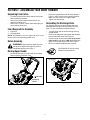
1
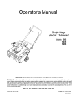
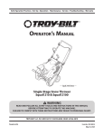
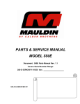
Operator’s Manual
Single Stage
Snow Thrower
Models 285 & 295
Models E285 &E295
IMPORTANT: Read safety rules and instructions carefully before operating equipment.
Warning: This unit is equipped with an internal combustion engine and should not be used on or near any unimproved forestcovered, brush-covered or grass-covered land unless the engine’s exhaust system is equipped with a spark arrester meeting
applicable local or state laws (if any). If a spark arrester is used, it should be maintained in effective working order by the operator.
In the State of California the above is required by law (Section 4442 of the California Public Resources Code). Other states may have
similar laws. Federal laws apply on federal lands. A spark arrester for the muffler is available through your nearest engine authorized
service dealer or contact the service department, P.O. Box 361131 Cleveland, Ohio 44136-0019.
MTD LLC, P.O. BOX 361131 CLEVELAND, OHIO 44136-0019
PRINTED IN U.S.A.
FORM NO. 770-10540C.fm
(7/2003)
TABLE OF CONTENTS
Content
Page
Important Safe Operation Practices .................................................................................. 3
Assembling Your Snow Thrower ....................................................................................... 5
Know Your Snow Thrower................................................................................................. 6
Operating Your Snow Thrower .......................................................................................... 7
Making Adjustments.......................................................................................................... 9
Maintaining Your Snow Thrower ....................................................................................... 10
Off-Season Storage .......................................................................................................... 10
Troubleshooting ................................................................................................................ 11
Parts List .......................................................................................................................... 12
FINDING MODEL NUMBER
This Operator’s Manual is an important part of your new snow thrower. It will help you to assemble, prepare and
maintain the unit for best performance. Please read and understand what it says.
Before you start assembling your new snow thrower, please locate the model plate on the
equipment and copy the information from it in the space provided below. The information on the
model plate is very important if you need help from our Customer Support Department or an
authorized dealer.
•
You can locate the model number by standing behind the unit in the operating position and looking down at
the dash panel . A sample model plate is explained below. For future reference, please copy the model
number and the serial number of the equipment in the space below.
Model Number ________________
Serial Number ________________
Copy the model number here:
www.yardman.com
MTD LLC
P. O. BOX 361131
CLEVELAND,OH 44136
330-220-4683
800-800-7310
Copy the serial number here:
ENGINE INFORMATION
The engine manufacturer is responsible for all engine-related issues with regards to performance, power-rating,
specifications, warranty and service. Please refer to the engine manufacturer’s Owner’s/Operator’s Manual packed
separately with your unit for more information.
CALLING CUSTOMER SUPPORT
Please do NOT return the unit to the retailer from which it was purchased, without first contacting Customer Support.
If you have difficulty assembling this product or have any questions regarding the controls, operation or
maintenance of this unit, please call 1- (330) 220-4MTD (4683) or 1- (800)-800-7310 to reach a
Customer Support representative. Please have your unit’s model number and serial number ready when
you call. See previous section to locate this information. You will be asked to enter the serial number in
order to process your call.
For more details about your unit, visit our website at www.yardman.com
2
SECTION 1: IMPORTANT SAFE OPERATION PRACTICES
WARNING: This symbol points out important safety instructions which, if not followed, could endanger
the personal safety and/or property of yourself and others. Read and follow all instructions in this manual
before attempting to operate this machine. Failure to comply with these instructions may result in personal
injury. When you see this symbol—heed its warning.
WARNING: Engine Exhaust, some of its constituents, and certain vehicle components contain or emit
chemicals known to State of California to cause cancer and birth defects or other reproductive harm.
DANGER: This machine was built to be operated according to the rules for safe operation in this manual. As with any type
of power equipment, carelessness or error on the part of the operator can result in serious injury. This machine is capable
of amputating hands and feet and throwing objects. Failure to observe the following safety instructions could result in
serious injury or death.
Training
1.
2.
3.
4.
5.
6.
7.
7.
Read, understand, and follow all instructions on the
machine and in the manual(s) before attempting to
assemble and operate. Keep this manual in a safe place
for future and regular reference and for ordering
replacement parts.
Be familiar with all controls and their proper operation.
Know how to stop the machine and disengage them
quickly.
Never allow children under 14 years old to operate this
machine. Children 14 years old and over should read and
understand the operation instructions and safety rules in
this manual and should be trained and supervised by a
parent.
Never allow adults to operate this machine without
proper instruction.
Thrown objects can cause serious personal injury. Plan
your snow throwing pattern to avoid discharge of material
toward roads, bystanders and the like.
Keep bystanders, helpers, pets and children at least 75
feet from the machine while it is in operation. Stop
machine if anyone enters the area.
Exercise caution to avoid slipping or falling, especially
when operating in reverse.
8.
9.
Preparation
1.
2.
3.
4.
5.
6.
Thoroughly inspect the area where the equipment is to
be used. Remove all door mats, newspapers, sleds,
boards, wires and other objects which could be tripped
over or thrown by the auger.
Always wear safety glasses or eye shields during
operation and while performing an adjustment or repair to
protect your eyes. Thrown objects which ricochet can
cause serious injury to the eyes.
Do not operate without wearing adequate winter outer
garments. Do not wear jewelry, long scarves or other
loose clothing which could become entangled in moving
parts. Wear footwear which will improve footing on
slippery surfaces.
Use a grounded three wire extension cord and receptacle
for all units with electric start engines.
Adjust collector housing height to clear gravel or crushed
rock surfaces.
Disengage the auger control bail before starting the
engine.
Never attempt to make any adjustments while engine is
running, except where specifically recommended in the
operator’s manual.
Let engine and machine adjust to outdoor temperature
before starting to clear snow.
To avoid personal injury or property damage use extreme
care in handling gasoline. Gasoline is extremely
flammable and the vapors are explosive. Serious
personal injury can occur when gasoline is spilled on
yourself or your clothes which can ignite. Wash your skin
and change clothes immediately.
a. Use only an approved gasoline container.
b. Extinguish all cigarettes, cigars, pipes and other
sources of ignition.
c. Never fuel machine indoors.
d. Never remove gas cap or add fuel while the
engine is hot or running.
e. Allow engine to cool at least two minutes before
refueling.
f. Never over fill fuel tank. Fill tank to no more than
½ inch below bottom of filler neck to provide space
for fuel expansion.
g. Replace gasoline cap and tighten securely.
h. If gasoline is spilled, wipe it off the engine and
equipment. Move machine to another area. Wait 5
minutes before starting the engine.
i. Never store the machine or fuel container inside
where there is an open flame, spark or pilot light
(e.g. furnace, water heater, space heater, clothes
dryer etc.).
j. Allow machine to cool at least 5 minutes before
storing.
Operation
1.
2.
3.
4.
3
Do not put hands or feet near rotating parts, in the auger
housing or discharge chute. Contact with rotating parts
can amputate hands and feet.
The auger control bail is a safety device. Never bypass
its operation. Doing so, makes the machine unsafe and
may cause personal injury.
The auger control bail must operate easily in both
directions and automatically return to the disengaged
position when released.
Never operate with a missing or damaged discharge
chute. Keep all safety devices in place and working.
5.
6.
7.
8.
9.
10.
11.
12.
13.
14.
15.
16.
17.
18.
19.
20.
Maintenance & Storage
Never run an engine indoors or in a poorly ventilated
area. Engine exhaust contains carbon monoxide, an
odorless and deadly gas.
Do not operate machine while under the influence of
alcohol or drugs.
Muffler and engine become hot and can cause a burn. Do
not touch.
Exercise extreme caution when operating on or crossing
gravel surfaces. Stay alert for hidden hazards or traffic.
Exercise caution when changing direction and while
operating on slopes.
Plan your snow throwing pattern to avoid discharge
towards windows, walls, cars etc. To avoid property
damage or personal injury caused by a ricochet.
Never direct discharge at children, bystanders and pets
or allow anyone in front of the machine.
Do not overload machine capacity by attempting to clear
snow at too fast of a rate.
Never operate this machine without good visibility or
light. Always be sure of your footing and keep a firm hold
on the handles. Walk, never run.
Disengage power to the auger when transporting or not
in use.
Never operate machine at high transport speeds on
slippery surfaces. Look down and behind and use care
when in reverse.
If the machine should start to vibrate abnormally, stop the
engine, disconnect the spark plug and ground it against
the engine. Inspect thoroughly for damage. Repair any
damage before starting and operating.
Disengage the auger control bail and stop engine before
you leave the operating position (behind the handles).
Wait until the auger comes to a complete stop before
unclogging the discharge chute, making any
adjustments, or inspections.
Never put your hand in the discharge or collector
openings. Always use a clearing tool to unclog the
discharge opening.
Use only attachments and accessories approved by the
manufacturer.
If situations occur which are not covered in this manual,
use care and good judgment. Contact your dealer or
telephone 1-800-800-7310 for assistance and the name
of your nearest servicing dealer.
1. Never tamper with safety devices. Check their proper
operation regularly.
Disengage the auger control bail and stop engine. Wait
until the auger comes to a complete stop. Disconnect the
spark plug wire and ground against the engine to prevent
unintended starting before cleaning, repairing, or
inspecting.
3. Check bolts, and screws for proper tightness at frequent
intervals to keep the machine in safe working condition.
Also, visually inspect machine for any damage.
4. Do not change the engine governor setting or over-speed
the engine. The governor controls the maximum safe
operating speed of the engine.
5. Snow thrower shave plates and skid shoes are subject to
wear and damage. For your safety protection, frequently
check all components and replace with original
equipment manufacturer’s (O.E.M.) parts only. “Use of
parts which do not meet the original equipment
specifications may lead to improper performance and
compromise safety!”
6. Check the auger control bail periodically to verify they
engage and disengage properly and adjust, if necessary.
Refer to the adjustment section in this operator’s manual
for instructions.
7. Maintain or replace safety and instruction labels, as
necessary.
8. Observe proper disposal laws and regulations for gas,
oil, etc. to protect the environment.
9. Prior to storing, run machine a few minutes to clear snow
from machine and prevent freeze up of auger.
10. Never store the machine or fuel container inside where
there is an open flame, spark or pilot light such as a water
heater, furnace ,clothes dryer etc.
11. Always refer to the operator’s manual for proper
instructions on off-season storage.
2.
Your Responsibility:
•
4
Restrict the use of this power machine to persons
who read, understand and follow the warnings and
instructions in this manual and on the machine.
SECTION 2: ASSEMBLING YOUR SNOW THROWER
Unpacking From Carton
•
•
•
•
Cut along corners of the carton and lay it down flat.
Remove packing material.
Remove any loose parts included with unit (i.e.,
operator’s manual, etc.).
Roll unit out of carton. Check carton thoroughly for
any remaining loose part.
•
Raise the upper handle in the direction shown in
Figure 1 until it clicks into the operating position.
Make sure not to pinch or crimp the cable.
Tighten the hand knobs.
Assembling the Discharge Chute
For shipping reasons, the snow thrower has been
packaged with the upper chute pivoted all the way
down. To pivot it upward, proceed as follows:
Items Required For Assembly
•
1. Engine oil
2. Fresh gasoline
•
NOTE: All references to left or right side of the snow
thrower is from the operating position only.
•
Before Assembly
•
WARNING: Disconnect the spark plug wire
Turn the chute until the chute opening is facing
straight ahead.
Remove the wing knob, flat washer and carriage
bolt from the lower chute. See Figure 2.
Pivot the upper chute upward over the lip on the
lower chute so that there is NO gap between the
upper chute and the lower chute. See Figure 2.
Re-secure with the hardware just removed.
and ground it against the engine to prevent
unintended starting. See Figure 1.
CAUTION:Do not use the Chute
Handle to lift the machine.
Raising Upper Handle
•
Loosen the hand knob on each side of the handle.
Remove packing material, if any.
Carriage Bolt
and Flat Washer
Wing Knob
Hand Knob
Spark Plug
Access
Figure 2
Figure 1
5
SECTION 3: KNOW YOUR SNOW THROWER
WARNING: Be familiar with all the controls on the snow thrower and their proper operation. Know how to
stop the machine and disengage them quickly.
Auger Control Handle
Recoil Starter
Gasoline Cap
Fuel Plug
Primer
Key
Electric Starter(If Equipped)
Spark Plug Access
Discharge
Chute
Oil Fill Plug
Choke
Lever
Auger
Shave Plate
Figure 3
Auger Control Handle
Primer Button
Located on the upper handle, the auger control handle
is used to engage and disengage the auger. The snow
thrower is designed to propel by the rotation of the
auger. Pull the auger control handle back against the
upper handle to engage the auger; release to
disengage.
Used to inject fuel directly into the carburetor to insure
fast starts in cold weather. Follow engine manual to
prime engine.
Ignition Key
Used to start engine. Put key in “ON” position to start
for both electric and recoil start engines. Follow starting
instructions given in the next section.
Discharge Chute
The angle of the discharge chute controls the distance
that the snow is thrown. Tilt the discharge chute up for
greater distance; tilt down for less distance. Loosen the
hand knob on the side of the discharge chute to adjust.
Tilt the chute to the desired position, and tighten the
knob.
Recoil Starter
Choke Lever
Requires use of a three-prong outdoor extension cord
The location of the choke lever is indicated in Figure 3
inset. You will have to use this lever to start the engine.
Push the lever all the way up to the FULL/ON position,
or all the way down to the OFF position as desired.
and a 120V power source
Used to manually start the engine.
Electric Starter (If Equipped)
Used to start engine with a 120V power source
Plug for Electric Start
Spark Plug Access
Spark plug located under the access cover.
Fuel Plug
Discard the fuel plug, before filling the fuel tank. It is
only used during assembly to keep dirt and debris out of
fuel tank.
6
SECTION 4: OPERATING YOUR SNOW THROWER
Before Starting
•
•
WARNING: Read, understand, and follow all
instructions and warnings on the machine and
in this manual before operating.
•
The spark plug wire was disconnected for safety.
Attach spark plug wire to spark plug before starting.
•
Gas and Oil Fill-Up
•
•
Check oil and gasoline level and add if necessary.
Follow related instructions in the separate engine
manual packed with your snow thrower.
WARNING: Use extreme care when
handling gasoline. Gasoline is extremely
flammable and the vapors are explosive. Never
fuel the machine indoors or while the engine is
hot or running. Extinguish cigarettes, cigars,
pipes and other sources of ignition.
•
•
•
To Start Engine
•
•
•
Insert ignition key into slot. Turn key to ON position.
Now follow the instructions below as it pertains to
your unit. See Figure 4 for location of controls.
•
Electric Starter(If Equipped)
WARNING: The electric starter must be
used with a properly grounded three-prong
receptacle at all times to avoid the possibility of
electric shock. Follow all instructions carefully
prior to operating the electric starter.
•
Recoil Starter
•
Press auger
control handle
to engage
auger
•
•
•
Primer
Move choke lever to FULL choke position (cold
engine start).
If engine is warm, place choke in OFF position
instead of FULL.
Push primer button two or three times for cold
engine start.
If engine is warm, push primer button only once.
NOTE: Always cover vent hole in primer button when
pushing. Additional priming may be necessary for first
start if temperature is below 15 degrees Fahrenheit.
Recoil
Starter
Key
•
Choke
Lever
The electric starter is equipped with a grounded
three-wire power cord and plug, and is designed to
operate on 120 volt AC household current.
Determine that your house wiring is a three-wire
grounded system. Ask a licensed electrician if you
are not certain.
If your home wiring system is not a three-wire
grounded system, do not use this electric starter
under any conditions.
If your home electrical system is grounded, but
a three-hole receptacle is not available, one should
be installed by a licensed electrician before using
the electric starter.
If you have a grounded three-prong receptacle,
proceed as follows.
Move Choke Control to “Full” position.
Push Primer three (3) times, making sure to cover
vent hole when pushing.Connect power cord to
switch box on dash panel. Plug the other end of
power cord into a three-prong 120-volt, grounded,
AC receptacle.
Push starter button to crank engine. As you crank
the engine, move choke lever to FULL choke
position.
When engine starts, release starter button, and
move choke gradually to OFF. If engine falters,
move choke immediately to FULL and then
gradually to OFF.
When disconnecting the power cord, always unplug
from the three-prong receptacle first, and then from
the snow thrower.
Electric
Starter
(If Equipped)
•
•
Spark Plug Access
Figure 4
7
Grasp starter handle and pull rope out slowly, until
it pulls slightly harder. Let rope rewind slowly.
Pull starter handle rapidly. Do not allow handle to
snap back. Allow it to rewind slowly while keeping a
firm hold on the starter handle.
As engine warms up and begins to operate evenly,
rotate choke lever slowly to OFF position. If engine
falters, return to FULL choke, then slowly move to
OFF position.
To Stop Engine
•
•
To stop engine, turn ignition key counter-clockwise.
Disconnect the spark plug wire from the spark plug
to prevent accidental starting while equipment is
unattended.
To help prevent possible freeze-up of starter,
proceed as follows:
•
•
•
•
Wing Knob
Upper Chute
Run engine for a few minutes before stopping to
help dry off any moisture on the engine.
Electric Starter (If Equipped): Connect power
cord to switch box on engine, then to 120 volt AC
receptacle. With the engine running, push starter
button and spin the starter for several seconds. The
unusual sound made by spinning the starter will not
harm engine or starter. Disconnect the power cord
from receptacle first, and then from switch box.
Recoil Starter: With engine running, pull starter
rope with a rapid, continuous full arm stroke three
or four times. Pulling the starter rope will produce a
loud clattering sound, which is not harmful to the
engine or starter.
Wipe all snow and moisture from the carburetor
cover in the area of the control levers. Also, move
control levers back and forth several times. Leave
throttle control lever in the STOP or OFF position.
Leave choke control in the FULL choke position.
Remove ignition key and disconnect spark plug
wire to prevent accidental starting.
Chute Handle
Figure 5
Operating Tips
•
•
Discharge snow downwind whenever possible.
Slightly overlap each previously cleared path.
Lifting up on the handle will allow the rubber on the
augers to propel the snow thrower forward. Pushing
downward on the handle will raise the augers off
the ground and stop forward motion.
NOTE: Excessive upward pressure on the handle will
result in premature wear on the rubber auger blades
which would not be covered by warranty.
•
Operating the Snow Thrower
•
The pitch of the discharge chute controls the angle at
which the snow is thrown.
•
Position the discharge chute opening by using the
Chute Handle to throw the snow in the desired
direction. See Figure 5.
Run the engine for a few minutes before stopping to
help dry any moisture on the engine.
Clean the snow thrower thoroughly after each use.
WARNING: Muffler, engine and surrounding
areas become hot and can cause a burn. Do
not touch.
Loosen the wing knob found on the left side of the
discharge chute and pivot the upper chute upward
or downward to the desired pitch. Retighten the
wing knob before operating the snow thrower.
8
SECTION 5: MAKING ADJUSTMENTS
WARNING: NEVER attempt to make any
adjustments while the engine is running,
except where specified in the operator’s
manual.
Shave Plate
•
To check the adjustment of the shave plate, place
the unit on a level surface. See Figure 6. The
wheels, shave plate and augers should all contact
level surface. Note that if the shave plate is
adjusted too high, snow may blow under the
housing. If the shave plate wears out excessively,
or the unit does not self-propel, the shave plate
may be too low and needs to be adjusted.
NOTE: On new units or units with a new shave plate
installed, the augers may be slightly off the ground.
Lock Nut & Carriage Bolt
Figure 7
Control Cable
As a result of both the control cable and the drive belt
stretching due to wear, periodic adjustments may be
necessary.
If the auger seems to hesitate when rotating while the
engine maintains a constant speed, an adjustment is
necessary. Proceed as follows:
Augers
The upper hole in the control handle provides an
adjustment in cable tension. To adjust, disconnect the
end of control cable from the bottom hole in the control
handle and reinsert it in the upper hole. Test the snow
thrower to see if there is a noticeable difference.
Shave Plate
Figure 6
•
To adjust, tip the snow thrower back so that it rests
on the handle. Loosen the four lock nuts and bolts
which secure the shave plate to the housing. See
Figure 7. Move the shave plate to desired position
and retighten the nuts and bolts securely.
Carburetor
WARNING: If any adjustments need to be
made to the engine while the engine is running
(e.g. carburetor), keep clear of all moving parts.
Be careful of muffler, engine and other
surrounding heated surfaces.
•
9
Refer to the separate engine manual, packed with
your unit, for carburetor adjustment information.
SECTION 6: MAINTAINING YOUR SNOW THROWER
Replacing Shave Plate
WARNING: Before servicing, repairing, or
The shave plate is attached to the bottom of the auger
housing and is subject to wear. It should be checked
periodically. There are two wearing edges and the
shave plate can be reversed. Refer to Figure 6.
inspecting, disengage the auger control bail
and stop engine. Wait until all moving parts
have come to a complete stop. Disconnect
spark plug wire and ground it against the
engine to prevent unintended starting.
•
Replacing Belt
•
•
Remove the belt cover by removing five hex
screws. See Figure 8.
•
Remove the four carriage bolts and hex lock nuts
which attach it to the snow thrower housing.
Install new shave plate, making sure the heads of
the carriage bolts are on the inside of the housing.
Adjust the shave plate according to instructions on
page 9. Tighten securely.
Engine
Hex
Screw
•
•
Refer to the separate engine manual for all engine
maintenance procedures.
Check engine and snow thrower frequently for
loose hardware, and tighten as needed.
Lubrication
Lubricate pivot points on the auger control handle and
the extension spring at the end of the control cable with
a light oil once every season and before storage of the
snow thrower at the end of the season.
Hex Screw
Belt Cover
Figure 8
•
Replacing the Auger’s Rubber Paddles
Pull up on the idler pulley and slip the belt off the
engine and auger pulley. See Figure 9.
The snow thrower auger’s rubber paddles are subject
to wear and should be replaced if any signs of
excessive wear is present.
Idler Pulley
NOTE: Call 1-800-800-7310 for information regarding
the price and availability of Auger Kit 753-04472 or
contact an authorized MTD Service Dealer in your
area).
Engine
Pulley
To change the rubber paddles, proceed as follows:
•
Auger
Pulley
•
Drive
Belt
Remove the existing rubber paddles by
unthreading the self-tapping screws which secure
them to the auger.
Secure the replacement rubber paddles to the
auger using the hardware removed earlier.
Figure 9
•
Reassemble new belt. Reinstall the belt cover.
SECTION 7: OFF-SEASON STORAGE
•
WARNING: Never store engine with fuel in
tank indoors or in enclosed, poorly ventilated
areas where fuel fumes may reach an open
flame, spark or pilot light as on a furnace, water
heater, clothes dryer, or other gas appliance.
•
•
•
Store in a clean, dry area. Block the snow thrower
up so it is not resting on the rubber auger blades.
NOTE: When storing in a metal storage shed, rustproof
the equipment, especially springs, cables and all
moving parts.When storing any type of power
equipment in a poorly ventilated or metal storage shed,
care should be taken to rustproof the equipment,
especially springs, cables and all moving parts.
Clean snow thrower thoroughly.
Lubricate as instructed above with a light oil.
Follow “Storage” instructions in the Engine Manual.
10
SECTION 8: TROUBLESHOOTING GUIDE
Problem
Cause
Remedy
Engine fails to start
1.
2.
3.
4.
5.
6.
7.
Fuel tank empty, or stale fuel
Blocked fuel line
Key not in ON position
Spark plug wire disconnected
Faulty spark plug
Engine not primed
Engine flooded with excessive priming
Engine runs erratic
1. Unit running on choke
2. Fuel line blocked, or stale fuel
1.
2.
3.
4.
5.
Fill tank with clean fresh gasoline.
Clean fuel line
Insert key and turn to ON position
Connect wire to spark plug.
Clean spark plug, readjust gap, or
replace.
6. Prime engine four times.
7. Wait at least ten minutes before
starting.
3. Water or dirt in fuel system
4. Carburetor out of adjustment
1. Move choke lever to OFF position.
2. Clean fuel line and fill tank with fresh,
clean gasoline.
3. Refer to engine manual for remedy.
4. Refer to engine manual for remedy.
Engine overheats
1. Carburetor out of adjustment
1. Refer to engine manual for instruction.
Loss of power
1. Spark plug wire loose
2. Vent in gas cap plugged
1. Connect and tighten spark plug wire.
2. Clear vent.
Excessive vibration
1. Loose parts or damaged auger
1. Stop engine immediately and
disconnect spark plug wire. Check for
possible damage. Tighten all bolts and
nuts. Repair as needed. If the problem
persists, take unit to an authorized
service dealer.
Unit fails to selfpropel
1. Control cable out of adjustment
1. Adjust control cable following
instructions on page 9 of this manual.
2. Replace drive belt
2. Drive belt loose or damaged
Unit fails to
discharge snow
1. Discharge chute clogged
2. Foreign object lodged in auger
3. Control cable not adjusted properly
4. Drive belt loose or damaged
1. Stop engine immediately and
disconnect spark plug wire. Clean
discharge chute and the auger
housing.
2. Stop engine immediately and
disconnect spark plug wire. Remove
object .
3. Adjust control cable following
instructions on page 9 of this manual.
4. Replace drive belt.
NOTE: For repairs beyond the minor adjustments listed above, contact your nearest authorized service
representative or call 1-800-800-7310 for the Customer Support Center. Refer to the engine manual for more
engine related information.
11
SECTION 9: PARTS LIST FOR MODELS 285, E285, 295 & E295
41
39
35
44
46
35
32
35
44
44
51
38
45
40
52
24
49
26
33
47
43
17
42
12
50
48
12
17
37
18
8
14
3
11
21
34
20
36
CABLE TO BE ABOVE
WHEEL AXEL
21
10
28
2
22
3
53
16
14
7 2723 31
4
1
29
13
25
17
13
9
12
22
10
9
28
30
19
15
12
6
Models 285, E285, 295 & E295
REF.
NO.
1
2
3
4
5
6
7
8
9
10
11
12
13
14
15
16
17
18
19
20
21
22
23
24
25
26
27
PART
NO.
684-04027
684-04028
710-0134
710-0167
710-0323
710-0352
710-0597
710-0642
710-0896
710-1005
712-0324
712-3010
712-3027
726-0299
731-1033
732-0357A
736-0119
736-0176
736-0326
736-0329
736-3090
741-0600
741-0919
746-04091
748-0234
749-04114
750-04230
REF.
NO.
28
29
30
31
32
33
DESCRIPTION
Auger Ass'y 21" complete w/Solid Shaft
Auger Housing Ass’y 21”
Screw, 1/4-20 x .62
Carriage Bolt 1/2-20 x .50 LG
Truss Mach Scr 5/16-18 x .75
Hex "B" Tap Scr. 1/4-14 x .375" LG
Hex Screw 1/4-20 x 1.00 Gr. 5
Hex Tap Scr. 1/4-20 x .75"
Hex Screw AB:1/4-14 x 0.625”
Hex Tap Scr. 1/4-14 x .50" LG.
Hex Nut, 1/4-20 Nylon
Hex Nut 5/16-18 hd. Gr. 5
Hex Flange Nut, 1/4-20
Push Cap x 1/2" Rod
Shave Plate 2.66 x 19.88 Double
Extension Spring .33 OD x 1.12 Lg.
L-Wash 5/16 ID
Flat Washer .265 ID x .938 OD x .120
Flat Washer .510 ID x 1.00 OD x .125
Lock Washer, 1/4
Flat Washer .260 x .720 x .060
Ball Bearing 17 x 40 x 12
Ball Bearing
Control Cable
Shoulder Spacer .25 THK
Lower Handle
Flange Spacer
34
35
36
37
38
39
40
41
42
43
44
45
46
47
48
49
50
51
52
53
NOTE: For painted parts, please refer to the list of color
codes below. Please add the applicable color code,
wherever needed, to the part number to order a
replacement part. For instance, if a part numbered 700xxxx is painted powder black, the part number to order
would be 700-xxxx-0637.
Yardman Green- 0665
13
PART
NO.
784-5174
790-00039
790-00045
790-00062
684-0178
684-04031
684-04032
710-0895
710-1003
710-1090
710-1882
710-3083
712-0252
712-0429
725-0201
725-2018
736-0225
736-0400
736-0451
7519636
710-0487
720-0284
710-0157
710-0451
747-04159
749-04106
734-04062
DESCRIPTION
Bearing Cup
Idler Bracket w/Brake
Belt Cover
Belt Keeper
Mitten Grip Bracket
Shroud Ass’y, 7HP Yellow
Shroud Ass’y, 5HP Yellow
Screw, 1/4-15 x .75
Hex Wash B-Tapp Scr #10-16 x .625" Lg.
Hex Flange Screw, 5/16-18x 1.25
Hex Flange Screw 5/16-18 x 1.50 Gr. 5
Hex Screw, 5/16-18 x 1.375
Hex Nut 5/8-32 x .12 Special
Hex Nut, 5/16-18 Gr 5 Nylon
Ignition Key
Key Switch-Electric Start
L-Washer Internal .625 ID x 1.058 OD
Flat Washer .194" ID x .62" OD x .063
Saddle Washer .320 ID x .93 OD
Recoil Handle, Mitten
Carriage Bolt 5/16-18 x 2.0 Gr. 1
Handle Knob Assembly 5/16-18
Hex Screw 5/16-24 x .75 Gr. 5
Carriage Bolt, 5/16-18 x.075 GR 1
Gull Wing Bail
Upper Handle, Gull Wing
Wheel, 7 x 1.5 Star Yellow
Models 285, E285, 295 & E295
9
3
11
11
4
1
8
2
5
6
12
10
7
REF.
NO.
1
2
3
4
5
6
7
8
9
10
11
12
PART
NO.
710-04071
710-0451
712-3068
720-0284
731-04127
731-04353
731-04373
731-04388
731-04429
732-04111
736-0159
684-04049
DESCRIPTION
Carriage Screw, 5/16-18 x 1.0
Carriage Bolt, 5/16-18 x.075 GR 1
Hex Patch I-Nut 5/16-18‘
Handle Knob Assembly 5/16-18
Lower Chute 5” Dia
Ring-Lower Chute
Chute, Adapter 5” Dia
Handle-Chute 5” Dia
Upper Chute w/Export Label
Chute Adjustment Spring
Flat Washer,.349 ID x .879 OD x .063
Lower Chute Ass’y (Incl. #5-7 and 10)
14
Models 285, E285, 295 & E295
18
16
1
19
5
12
10
17
9
7
8
13
6
3
21
15
21
14
23
4
22
2
20
REF.
NO.
1
2
3
4
5
6
7
8
9
10
12
13
14
15
16
17
18
19
20
21
22
23
PART
NO.
629-0071
710-0157
710-0409
710-0654A
710-0751
710-1003
712-0324
719-0581
726-0205
726-0470
731-2825
736-0119
736-0242
736-0337
747-04169
751-0535
751-0603
751-10023
751-0101A
756-04060
756-0475
790-00047
DESCRIPTION
Extension Cord
Hex Screw, 5/16-24 x .75
Hex Screw, 5/16-24 x 1.75
Self Tapping Screw, 3/8-16 x 1.00
Hex Screw, 1/4-20 x .62
Screw, #10-16 x .625
Hex Nut, 1/4-20 Nylon
Spacer, Engine 4 Cycle
Clamp, Hose
Cable Tie
Knob, Choke
Washer, Lock 5/16
Bell Washer, .340 x .872 x .060
Flat Washer, 5/8 ID x 1.0 OD
Support, Wire Gas Tank
Hose, Fuel Line
Cap, Fuel
Tank, Fuel
V-Belt 1/2 x 35.0 LG
Pulley Half, .625 ID x 2.25 OD
Pulley, 1/2 V 1/2-20 LH x 6.0
Bracket, Engine 4 Cycle
15
MANUFACTURER’S LIMITED WARRANTY FOR:
The limited warranty set forth below is given by MTD LLC with
respect to new merchandise purchased and used in the
United States, its possessions and territories.
“MTD” warrants this product against defects in material and
workmanship for a period of two (2) years commencing on the
date of original purchase and will, at its option, repair or
replace, free of charge, any part found to be defective in
materials or workmanship. This limited warranty shall only
apply if this product has been operated and maintained in
accordance with the Operator’s Manual furnished with the
product, and has not been subject to misuse, abuse,
commercial use, neglect, accident, improper maintenance,
alteration, vandalism, theft, fire, water, or damage because of
other peril or natural disaster. Damage resulting from the
installation or use of any part, accessory or attachment not
approved by MTD for use with the product(s) covered by this
manual will void your warranty as to any resulting damage.
Normal wear parts or components thereof are subject to
separate terms as follows: All normal wear parts or
component failures will be covered on the product for a period
of 90 days regardless of cause. After 90 days, but within the
two year period, normal wear part failures will be covered
ONLY IF caused by defects in materials or workmanship of
OTHER component parts. Normal wear parts and
components include, but are not limited to: batteries, belts,
blades, blade adapters, grass bags, rider deck wheels, seats,
snow thrower skid shoes, shave plates, auger spiral rubber,
and tires.
HOW TO OBTAIN SERVICE: Warranty service is available,
WITH PROOF OF PURCHASE, through your local authorized
service dealer. To locate the dealer in your area, check your
Yellow Pages, or contact MTD LLC at P.O. Box 361131,
Cleveland, Ohio 44136-0019, or call 1-800-800-7310 or log
on to our Web site at www.mtdproducts.com.
This limited warranty does not provide coverage in the
following cases:
a.
b.
c.
The engine or component parts thereof. These items
may carry a separate manufacturer’s warranty. Refer
to applicable manufacturer’s warranty for terms and
conditions.
Log splitter pumps, valves, and cylinders have a sepa
rate one year warranty.
Routine maintenance items such as lubricants, filters,
blade sharpening, tune-ups, brake adjustments, clutch
adjustments, deck adjustments, and normal
deterioration of the exterior finish due to use or
exposure.
d.
e.
f.
g.
MTD does not extend any warranty for products sold or
exported outside of the United States, its possessions
and territories, except those sold through MTD’s
authorized channels of export distribution.
Replacement parts that are not genuine MTD parts.
Service completed by someone other than an
authorized service dealer.
Transportation charges and service calls.
No implied warranty, including any implied warranty of
merchantability of fitness for a particular purpose,
applies after the applicable period of express written
warranty above as to the parts as identified. No other
express warranty, whether written or oral, except as
mentioned above, given by any person or entity,
including a dealer or retailer, with respect to any product,
shall bind MTD. During the period of the warranty, the
exclusive remedy is repair or replacement of the product
as set forth above.
The provisions as set forth in this warranty provide the
sole and exclusive remedy arising from the sale. MTD
shall not be liable for incidental or consequential loss or
damage including, without limitation, expenses incurred
for substitute or replacement lawn care services or for
rental expenses to temporarily replace a warranted
product.
Some states do not allow the exclusion or limitation of
incidental or consequential damages, or limitations on how
long an implied warranty lasts, so the above exclusions or
limitations may not apply to you.
In no event shall recovery of any kind be greater than the
amount of the purchase price of the product sold. Alteration
of safety features of the product shall void this warranty.
You assume the risk and liability for loss, damage, or injury to
you and your property and/or to others and their property
arising out of the misuse or inability to use the product.
This limited warranty shall not extend to anyone other than the
original purchaser or to the person for whom it was purchased
as a gift.
HOW STATE LAW RELATES TO THIS WARRANTY: This
limited warranty gives you specific legal rights, and you may
also have other rights which vary from state to state.
IMPORTANT: Owner must present Original Proof of Purchase to obtain warranty coverage.
MTD LLC, P.O. BOX 361131 CLEVELAND, OHIO 44136-0019; Phone: 1-800-800-7310