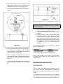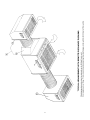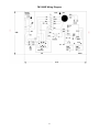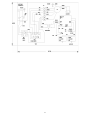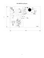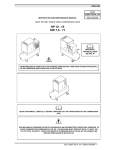
1
Model FM 1000
Electronic & Media Air Cleaner
Installation
Operation
Service
Please read these instructions carefully for
trouble free operation and to get the most out of
your purchase.
For further information
concerning this project, contact your local Trion
representative
101 McNeill Road • Sanford, NC 27330
Phone: 800-884-0002 • Fax: 800-458-2379 • Email: [email protected]
www.trioninc.com
Manual Part No. 140627-001 • June 2002
to change the filter and wash the pre-filter. (From 1 to 4
months, depending on the application).
SPECIFICATIONS
FM 1000 Electrostatic
Input Voltage:
Amp Draw:
Unit Weight:
Air Output:
Options:
The media main filter and charcoal after-filter are
disposable when dirty. Replace with new filters from your
authorized Trion Representative.
120 V, 60 HZ, 1 PH
3.1 Max.
108 lbs.
600, 800 and 1100 CFM (nominal)
1. Charcoal After Filter
2. Remote Discharge
OPERATION
CONTROL SWITCH
The 3 position control switch located on the exposed
side of the installed unit, controls the operation of the
power supply and the speed of the fan: Low, Medium or
High. (Power Supply not needed on FM 1000 Media
Unit).
FM 1000 Media
Input Voltage:
Amp Draw:
Unit Weight:
Air Output:
Options:
120 V, 60 HZ, 1 PH
4.0 Max
88 lbs.
400, 500 and 650 CFM (nominal)
1. Charcoal After Filter
2. Remote Discharge
LED LIGHTS (Red not used on FM 1000M)
The green LED indicates the unit has electrical power
and the switch has been turned to one of the 3 positions.
This manual provides information for location,
installation, operation and service of the FM 1000 E & M.
Before installation and use of the air cleaner, carefully
read these instructions to insure maximum benefits from
the unit and to avoid needless service cost that result
from improper installation.
The Red LED indicates High Voltage (approximately
6800 VDC) is supplied to the Ionizer / Collector cell.
(Red not used on Media unit).
FILTER ACCESS
The filter access screws located on the access door of
the unit hold the access door closed, and are designed
to automatically disconnect electrical power when the
access door is opened (Item 6, Page 5). The access
door may be removed for convenience of unit installation
and cleaning once in operation.
FM 1000 E ELECTROSTATIC
The FM 1000 E electronic air cleaner is technically
known as a two-stage electrostatic precipitator. It is
designed to remove airborne particles, dust, dirt, smoke
or other indoor air pollutants.
INSTALLATION
Air movement through the unit is controlled by its own
blower system. As dirty air enters the unit, it passes
through a pre-filter, which removes large particles by
direct impingement.
Read instructions carefully before beginning installation.
CAUTION:
ELECTRONIC AIR CLEANERS CANNOT BE USED IN
AREAS WHERE COMBUSTIBLE GASES OR VAPORS
ARE
PRESENT.
USE
GLOVES
DURING
INSTALLATION TO PREVENT POSSIBLE INJURY
FROM EXPOSED METAL.
The pre-filtered air then passes through a two-stage
electrostatic precipitator. In the first stage of electrical
operation, all airborne particles, even of submicroscopic
size are electrically charged (positive) as they pass
through the ionizer. In the second stage of operation, the
charged particles pass into an electrical field established
between a series of parallel plates, forming the negative
element of the field established between a series of
parallel plates that collect airborne particulate.
T-BAR CEILING INSTALLATION
DO NOT INSTALL THE UNIT IN A T-BAR CEILING
UNLESS THE UNIT CAN BE SECURED TO THE
PERMANENT CEILING OR CEILING JOIST, BEAMS,
ETC. AS DESCRIBED HEREIN.
FM 1000M MEDIA FILTER
The FM 1000M with media filtration instead of an
Ionizer/Collector cell utilizes the same type pre-filter but
a mechanical media or fabric main filter to trap airborne
pollutants in the filter fibers. As more pollutants are
collected, the efficiency of the media filter is increased to
a point where air delivery from the unit is reduced and
effective air cleaning does not take place. It is then time
1. Installer must provide the 2/0 chain or other
hanger material as required.
2. Carefully unpack the unit and check for damage
incurred in shipment. Report any damage to the
freight carrier and your TRION Representative
immediately.
2
3. Open Filter access door and remove it. Also
remove both collector cells or media filter and
set aside being careful not to damage either.
4. Install eyebolts provided with unit as shown in
Sketch A.
CAUTION:
DO NOT ALLOW FULL WEIGHT OF UNIT TO REST
ON T-BAR CEILING.
8. Install mounting trim brackets to each side to fill
in the gap between the unit and T-Bar.
9. Connect electrical power to the unit. See Wiring
Diagram.
10. If optional carbon filter is used, remove filter
from plastic bag and install in the guide rails
provided inside the cabinet behind the main
filter. Replace the main filter and pre-filter / door
assembly. Close the door and secure by turning
the quarter turn fasteners clockwise with a coin
or screwdriver. The unit is now ready for
operation.
The following information will be required for prompt
delivery of repair parts:
5. Select mounting location as near to the center of
the area to be cleaned or at the point
recommended by your TRION Representative.
Remove a section of ceiling tile.
Description
1. Unit model number
2. Unit serial number
3. Part number and description
6. Attach a length of safety chain (2.0 Min.) or
equivalent rod, cable or other hanger material to
each of the four eyebolts. Fasten securely. See
Sketch A.
When a part number is not listed, give the above
information and include the item number from the
exploded views.
7. Lift unit into place and support while securing to
permanent ceiling, ceiling joist, etc. (See Sketch
B)
Located
Inside door
Inside door
Exploded views.
MAINTENANCE AND WASHING
MAINTENANCE
When to Wash: Periodically the dirt collected by your
unit must be removed. The frequency of washing will
depend on the amount of dirt present in the air in your
locality.
The washing frequency best suited for your unit can be
determined by examining the dirt collected components
at three week intervals. As the dirt begins to collect, you
3
will notice a light film, then a very definite collection will
be evident at a later examination. When there is a
noticeable build-up of dirt, it is time to wash.
input line voltage. A minimum voltage of 108 VAC is
required.
After assembling and installing the unit, turn the control
switch to one of the 3 positions.
In most areas the collecting cell should be washed every
12 weeks.
1. The unit’s green “on” light should now be on
indicating the unit has line voltage.
2. The voltage to the cell light (red) should be on
indicating high voltage is being sent from the
power supply to the cell. (Not on FM 1000
Media).
NOTE:
Dirt build-up on the ionizing–collecting cell should not be
confused with dirt stains. Dirt stains are normal and
should not affect efficiency.
STEPS FOR WASHING (Electronic Units Only)
ARCING (SNAPPING OR CRACKING NOISE)
Does not apply to FM 1000 Media
1. Switch control switch “OFF”.
2. Remove pre-filter and cell.
3. Place components in automatic dishwasher,
stationary tub, shower stall or over floor drain.
Use hot soapy water and rinse thoroughly.
(Ionizing wires are easily broken. Handle the
cells with care.)
4. Replace pre-filter and cell.
5. Close cell access door.
6. Switch control switch to “ON”.
If arcing noise occurs due to wet cells, turn
switch off and allow more drying time.
If there are any problems, refer to the service
check list.
An occasional arcing noise may be emitted from the air
cleaner. This is normal and is caused by an
exceptionally large piece of dirt or other matter entering
the collecting cell. An arcing noise may also be noted
after cell washing. If this occurs and is consistent, allow
more time for the cell to dry. Refer to Troubleshooting
Chart.
CAUTION:
TROUBLESHOOTING WILL EXPOSE HAZARDOUS
LIVE PARTS. DISCONNECT POWER BEFORE
PROCEEDING. ALLOW THE CELL TO DISCHARGE
AT LEAST 2 MINUTES AFTER POWER HAS BEEN
TURNED OFF TO INSURE THERE IS NO RESIDUAL
CHARGE.
FM 1000E ELECTROSTATIC
TROUBLESHOOTING
THE FOLLOWING INSTRUCTIONS ARE FOR USE BY
QUALIFIED PERSONNEL.
FM 1000 MEDIA
TROUBLESHOOTING
WARNING:
THE FOLLOWING PROCEDURES WILL EXPOSE
HAZARDOUS LIVE PARTS. DISCONNECT THE AIR
CLEANER BEFORE PROCEEDING.
THE FOLLOWING INSTRUCTIONS ARE FOR USE BY
QUALIFIED PERSONNEL.
WARNING:
THE FOLLOWING PROCEDURES WILL EXPOSE
HAZARDOUS LIVE PARTS. DISCONNECT THE AIR
CLEANER BEFORE PROCEEDING.
All TRION Electronic Air Cleaners are manufactured to
give the user continued trouble-free service. However,
as with all mechanical equipment breakdowns do occur.
All TRION Air Cleaners are manufactured to give the
user continued, trouble-free service. However, as with all
mechanical equipment, breakdowns do occur.
The Troubleshooting Chart on this page will enable the
user to pinpoint the cause of most problems. Refer to the
Ordering Information section for replacement parts.
Troubleshooting the unit is very easy as there are only
three electrical components in the unit; the motor with
the capacitor, the speed controller, and a light.
Before troubleshooting the unit, refer to the Wiring
Diagram; check for proper wiring connections and the
4
TROUBLESHOOTING
PROBLEM
SOLUTION
Unit does not operate
Light not on
1. Check 120 VAC input power
2. Broken lead in power cord
3. Bad speed controller
Light on
Blower does not run
1. Broken wire between the speed controller
and the motor
2. Bad motor capacitor
3. Bad motor
5
6
FM 1000 E & M Unit Assembly Parts List
Item
Part Number
1
2
3
4
4A
4B
5
6
440549-001
227833-006
228276-001
139999-001
244223-001
244224-001
240550-001
120034-506
Description
Discharge grill (2 req.)
Charcoal afterfilter (2 req.)
Switch, 3 speed rotary
Knob, switch
Label, control switch ESP (not shown)
Label, control switch Media (not shown)
Pre-filter, aluminum mesh
Machine screw (2 req.)
7
6A
6B
7
8
9
10
10A
11
12
13
14
15
16
16A
17
17A
18
19
20
21
22
23
24
25
26
27
28
29
244225-004
120456-001
440541-001
422086-504
340553-001
140551-001
140552-001
240537-001
340623-001
234458-006
341677-601F
134516-013
134516-007
140568-002
240060-001
2400061-001
129040-003
132322-001
132311-001
440734-001
340564-001
440559-001
340546-001
220111-029
140569-001
340659-001
340660-001
240636-001
Retainer (2 req.)
Nylon Washer (2 req.) (not shown)
Access door
Ionizer/collector cell (electrostatic)
Pleated media filter (Media)
4 blade fan (electrostatic)
5 blade fan (Media)
Collector cell latch
Motor
High voltage contact board assy. (2 req)
Circuit board power supply
LED light assy. (red electrostatic)
LED light assy. (green electrostatic)
LED light assy. (green media)
Name Plate (ESP)
Name plate (Media)
Capacitor
Cap, Switch
Safety Switch
Remote discharge kit-less duct-Includes Items 22 & 23
Plenum inlet adaptor (remote only) (2)
Cabinet outlet adapter (remote only) (2)
Outlet plenum
Ionizer wire assy. (10 req.)
Resistor assy. (Media only, not shown)
Positioning bracket (Long 2 req.)
Positioning bracket (Short 4 req.)
Step down transformer
8
9
10
11
FM 1000E Wiring Diagram
12
13
FM 1000M Wiring Diagram
14
WARRANTY
All Trion air cleaners are warranted for component failure and workmanship for a
period of three years after purchase. Do not return defective parts without prior
permission from the factory. Contact your local Trion Distributor or Trion Customer
Service Department at 1-800-884-002 of Fax 1-800-458-2379 to obtain
material return authorizations and service information.
Form No. 147527-001
June 2002
Corporate Office: 101 McNeill Road • Sanford, NC 27330
Phone: 800-884-0002 • Fax: 800-458-2379 • Email: [email protected]
www.trioninc.com