1
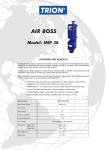
ELECTRONIC
AIR PURIFICATION
SYSTEM
Eliminator
Series
SE400E and SE800E
•
•
•
INSTALLATION
OPERATION
SERVICE
Electrostatic Precipitators for
Commercial Applications
101 McNeill Road • Sanford, NC 27330
(919) 775-2201 • Fax: (919) 777-6399 • (800) 884-0002
www.trioninc.com
MANUAL PART NO. 154385-002 • September 2001
1
Contents
Section I – Design
1. Introduction………………………..
Page
3
2. The Filter System…………………
3
3. Specifications……………………..
4
Section II - Installation
1. Installation…………………………
5-6
2. Diagrams…………………………..
7
Section III – Servicing and Maintenance
1. Servicing / Maintenance…………
8
2. Parts List…………………………..
9
3. Exploded Views…………………..
10
Section IV - Reference
1. Wiring Diagram SE400E…………
11
2. Wiring Diagram SE 800E………..
12
This manual provides information for installation, operation and maintenance of
your Trion SE400E & SE800E. Before installing and using the air purifier, carefully
read these instructions to ensure maximum benefits from the unit, and to avoid
needless service costs that may result from improper installation
and maintenance.
2
Eliminator SE Series
2. The Filter System
Section I – Design
There are two filters in your air cleaner THE PRE-FILTER: This is the mechanical
filter that lies behind the inlet grill. It is
designed to remove large particles and can be
washed many times before replacement.
1. Introduction
The Trion Eliminator SE400E & SE800E are
commercial air purifiers that have been
specifically designed to remove airborne
pollutants - including tobacco smoke, dust,
pollen and mold spores - in rooms and areas
where people work or relax. They are
designed to be mounted onto a solid ceiling,
semi-recessed for into a suspended ceiling, or
wall mounted (SE400E only). Where
appropriate they can also draw in additional
fresh air.
Their features make them the ideal air purifier
for installations into areas such as offices,
conference rooms, restaurants, designated
smoking areas, institutions and waiting rooms
or any other place where people gather.
THE ELECTROSTATIC FILTER: This is the
deep aluminum assembly (Collector Cell)
located immediately behind the pre-filter and
is the heart of your air cleaner. It uses an
electrostatic charge to remove particles so
small that it would take a pile of many millions
to cover a pinhead. When dirty it can be
washed and reused indefinitely.
FILTER REMOVAL
TRION SE400E
Turn the control switch off before removing cell.
Press the two cell access latches and the hinged
door will swing down. Remove pre-filter by turning
pre-filter clip 90 degrees (fig 2). While supporting
the weight of the Collector Cell, loosen the filter
retaining screw (fig 3). The filter retaining plate will
now open allowing the filter to be removed (fig 4).
To reinstall the filter, simply reverse above
procedure.
HOW THEY WORK
The Trion SE400E & SE800E utilize the
principle of Electrostatic Precipitation. Air is
drawn into the intake, through the metal
prefilter, which traps lint and large dust
particles. The remaining particles, some as
small as 0.01 microns*, pass into a strong
electrical field (ionizing section) where the
particles receive an electrical charge. The
charged particles pass onto a series of equally
spaced parallel plates (collector section). Each
alternate plate is charged with the same
polarity as the particles, which are repelled,
while the interleaving plates are grounded, and
therefore attract and collect the particles.
TRION SE800E
The two hinged access doors are secured with
retaining screws (fig 3). Release screws to
allow the doors to swing down. Remove the
Collector Cells as described above.
INSTALLATION LOCATION
The most effective location for the air purifier is
the center of the area to be cleaned because
the dirty air is pulled into the center of the unit
and discharged equally out the four sides. If
more than one unit is required, space them
evenly over the area to be cleaned.
* The diameter of a human hair is about 100
micron!
3
Eliminator SE Series
3. Specifications
Model
SE400E
SE800E
Dimensions
Depth:
Width:
Length:
Installation
Surface mounted, recessed into suspended ceiling,
or wall (SE400E only) mounted.
Weight
42 lbs. / shipping 48 lbs.
80 lbs. / shipping 86 lbs.
Input Power
120 Volts, 1 Phase, 60 Hz
120 Volts, 1 Phase, 60 Hz
Power Consumed
1.8 Amps, 155 Watts
3.4 Amps, 270 Watts
Controls
Hard-wired remote control
with 3-speed selector switch
with air-dry (fan only) facility
Hard wired remote control
with 3-speed selector switch
with air dry (fan only) facility
Motor
1/20 HP, 3-speed, Ball Bearing
(2) 1/20 HP, 3-speed, Ball Bearing
Air Flow
200, 300, 400 CFM
400, 600, 800 CFM
Sound Rating
38, 55, 62 dBa
41, 58, 65 dBa
Safety Feature
Interlock to cell access door
Interlock to cell access door
Features
Anti-arc circuitry
Power to cell indicator
Fresh air inlet
Dry (fan only) cycle
Anti-arc circuitry
Power to cell indicator
Fresh air inlet
Dry (fan only) cycle
Options
Infrared remote control
Fresh air damper system
Infrared remote control
Fresh air damper system
9.5”
22.5”
22.5”
Depth:
Width:
Length:
4
9.5”
22.5”
46.12”
g) Make electrical connections as detailed in next
section.
h) Re-install cell and prefilter.
i) Close access door and unit is ready for
operation.
Eliminator SE400E & SE800E
Section II – Installation
1. INSTALLATION
SOLID CEILNG MOUNTING
CAUTION:
To mount the unit to a solid ceiling, proceed
as follows:
a) Unpack the unit, open filter access door
and remove prefilter and cell (see filter
removal in section 2).
b) Select a location near the center of the
area to be cleaned. lf you are fitting to
wooden ceiling joists, locate the position
of joists.
c) Using the template provided, drill four
holes into the ceiling and fit four 5/16 lag
screws in the joists. Hex-headed screws
will give easier access for final tightening.
Do not tighten fully home.
d) Lift the unit to where the large end of the
keyhole slots in the top of the cabinet fit
over the screw heads. Slide the unit so
that the narrow ends of the mounting
slots are located under the screw heads.
Tighten the screws fully home.
e) Install the lockdown location screw as
shown on template.
f) Make electrical connections as detailed in
next section.
g) Re-install cell and pre-filter.
h) Close access door and unit is ready for
operation.
ELECTRONIC AIR CLEANERS
CANNOT BE USED IN AREAS WHERE
COMBUSTIBLE GASES OR VAPORS
ARE PRESENT.
MECHANICAL
The unit has been designed so that it can fit
either surface mounted onto the ceiling,
semi-recessed into a T-Bar suspended
ceiling or wall mounted (SE400E only).
When installed with a T-Bar suspended
ceiling NEVER support the unit from the TBars, the unit must be supported from the
permanent ceiling.
SUSPENDED CEILING INSTALLATION
To hang the unit into a suspended ceiling,
proceed as follows:
a) Unpack the unit, open filter access door
and remove prefilter and cell (see filter
removal in section 2).
b) Install ¼-20 eyebolts into mounting slots
with large diameter washers and lock-nuts as
shown in sketch A. Alternatively, use drop
rods.
c) Install trim as shown in sketch A.
d) Select and remove a ceiling tile near the
center of the area to be cleaned by the unit.
e) Attach a length of safety chain to each of
the four eyebolts or fit threaded rod. Fasten
securely.
f) Lift unit into place and support unit while
securing to permanent ceiling, ceiling
joists, etc. See sketch A.
WALL MOUNTED (SE400E Only)
Filter removal will be simpler if the unit is
positioned with the access door hinge in a
vertical plane. Locate the wall studs and
follow the mounting instructions for SOLID
CEILING MOUNTING.
ELECTRICAL:WARNING:
THIS APPLIANCE MUST BE
ELECTRICALLY GROUNDED.
CAUTION:
IT IS THE RESPONSIBILITY OF THE
INSTALLER TO ENSURE ADEQUATE
MOUNTING COMPONENTS ARE USED.
NOTE: This unit is designed to be
permanently connected to fixed
wiring. Installation must comply with
all applicable electrical codes.
DO NOT ALLOW WEIGHT OF UNIT TO
REST ON SUSPENDED CEILING
SUPPORT RAILS.
5
Hard wired remote control
Two sets of wiring are required to connect
the unit. Main power to the unit is 120V,
60Hz, 1Ph, rated 5 Amp - Live, Neutral and
Ground. A 5-conductor 5 Amp rated cable is
required from the unit to remote control.
Run the 5-conductor cable and the main
power connection through the cable entry
knockouts (see Fig. 5) in the cabinet and
connect to the input terminal block (Fig. 6) as
shown in the wiring diagram on page 10 and
11. Mount the remote control in the desired
position and connect the 5-conductor cable
leads to the numbered terminals as shown in
the wiring diagram.
OPTIONAL INFRARED CONTROL
Main power to the unit is 120V, 60Hz, 1Ph,
rated 5 Amp - Live, Neutral and Ground. To
install, follow the instructions included with
the infrared control kit.
6
2. Diagrams
FIGURE 1.
FIGURE 2.
FIGURE 3.
FIGURE 4.
FIGURE 5.
FIGURE 6.
7
Section III – Service and Maintenance
1. SERVICING AND MAINTENANCE
Beyond an occasional wipe down with a damp
cloth, the units need little in the way of
maintenance.
However, the units are designed to collect
airborne dirt and from time to time will require
routine servicing to remove the accumulation.
The service interval varies considerably between
applications, but typically will range from six
weeks in a busy bar up to several months in a
quiet office.
During normal operation, the unit will make an
occasional snapping noise. This is caused by
large pieces of dirt accumulating on the electronic
filter and is not dangerous. The Trion SE400E &
SE800E units have anti-arcing circuitry to
eliminate the nuisance of constant arcing. If,
however, the arcing occurs every minute or two, it
is an indication that the unit needs cleaning.
When a service is due proceed as follows:
a) Remove pre-filter and either vacuum clean it or
wash as described below.
b) To clean the electronic filter, soak it in a hot
(not boiling), a strong non-caustic detergent
solution cleaner.
Trion can supply an excellent detergent- TriDexobtainable through your Dealer. Alternatively, a
dishwasher detergent does an excellent job.
Soak the collector cell for several hours, then
rinse with clean water. Do not physically try to rub
the dirt off since this can cause damage to the
filter.
c) Allow the filter to dry thoroughly - preferably
overnight- and replace into the unit or alternatively
use force air dry setting on the unit.
Trion has a policy of continuous product
improvement, and reserves the right to make
changes in design and specification without
notice.
8
2. PARTS LIST
Item
Part Number
Description
Qty/Unit
SE400E
Qty/Unit
SE800E
1
2
3
4
5
6
7
8
9
10
11
12
13
14
15
16
17
18
19
20
21
22
23
24
25
26
27
28
29
30
31
32
33
34
35
36
37
37a
37b
454027-001
454028-001
453844-001
453844-003
453845-001
153853-001
453855-001
453856-001
453857-001
253863-001
441730-103
150685-001
353842-001
153854-001
244225-002
345109-001
453840-001
453841-001
242404-002
147214-001
350950-003
254167-003
254167-004
453847-001
254026-002
142153-001
254101-001
453858-001
EST-1124
253850-001
253851-001
153848-001
153849-001
253852-001
120035-210
234711-002
354267-001
250056-001
242235-001
Cabinet Assembly, SE400E
Cabinet Assembly, SE800E
Cell Access Cover
Discharge Cover
Cell Access Cover
Hinge Pin
Grill
Corner
Grill Filler
Pre-filter
Collector Cell
Cell Retaining Clip
Cell Latch
Thumb Screw
Bolt Retainer
Cell Contact Assembly
Cell Contact Support
Cell Contact Support
Interlock Switch
Insulator
Power Supply Assembly
Step-down Transformer 120V/24V
Step-down Transformer 120V/24V
Motor Mounting Bracket
Motor, 120V/60Hz
Ground Contact
Fan
Inlet Ring
Terminal Block
Terminal Block Cover
Duct Cover Plate
Interlock Switch Actuator
Interlock Switch Actuator
Access Cover Latch
Flat Head Screw
Retaining Nut
Remote Control Assembly
Rotary Switch
Switch Knob
1
1
1
2
4
4
1
1
1
1
1
1
1
1
2
2
1
1
1
1
1
1
1
1
1
1
1
2
1
1
1
1
2
2
4
6
4
2
2
2
2
2
2
6
2
1
4
4
1
1
2
2
2
2
2
1
1
2
2
4
4
1
1
1
9
3. Exploded Views
SE400E
SE800E
10
Section IV – Reference
1. WIRING DIAGRAM SE400E
11
2. WIRING DIAGRAM SE800E
WARRANTY
All Trion air cleaners are warranted for component failure and workmanship for a period of three years after
purchase. Do not return defective parts without prior permission from the factory. Contact your local Trion
Distributor or Trion Customer Service Department at 800-884-0002 or Fax 800-458-2379 to obtain material
return authorizations and service information.
101 McNeill Road • Sanford, NC 27331-0760
Customer Service: (800) 884-0002 • Fax: (800) 458-2379
www.trioninc.com • email: [email protected]
Manual Part Number 154385-002, June 2001
12