1
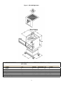
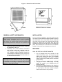
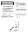
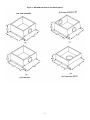
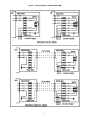
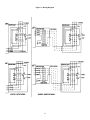
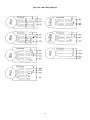
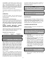
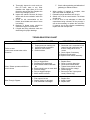
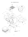
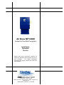
Air Boss MP 600M
Vertical Air Flow Mist Precipitator
Installation
Operation
Service
Please read these instructions carefully for
trouble free operation and to get the most out of
your purchase.
For further information
concerning this project, contact your local Trion
representative.
101 McNeill Road • Sanford, NC 27330
Phone: 800-884-0002 • Fax: 800-458-2379 • Email: [email protected]
www.trioninc.com
Manual Part No. 153632-001 • June 2002
DESCRIPTION
POSITION AIR CLEANER CABINET
The Trion MP 600M air cleaner is designed to capture
machine tool fluids, metal dust and smoke for clean air
filtration. It can be mounted to a wall, frame, platform, or
directly on the machine tool. Mist, dust, and smoke are
drawn from each machine through an external duct into
the air cleaner. A self-draining Impinger removes the
heavy mist and droplets (including water soluble fluids),
and the remaining contaminates are captured by the prefilter and the primary filter. Clean air is returned to the
plant through the vertical discharge. The air cleaner
operates at 95-99.97% efficiency at the rated 600 CFM
airflow.
To reduce weight for ease in handling, remove the prefilters, main filters and place them safely aside. Position
the cabinet in the designated location giving
consideration to following points:
(a) Provide sufficient clearance in front of the
access doors for mechanical filter replacement.
A minimum of 26” is required (see figure 2).
(b) Level the cabinet to assure proper drainage from
the drain pan.
(c) Unless specific design features have been
prearranged, the direction of air flow through th
e cabinet may be from any side or upward
through the bottom. When the filters are
reinstalled, the directional arrows on the filters
must concur with airflow through the cabinet. If
mist suppressors have been specified, they are
to be installed on the air entering side of the unit.
NEW UNIT INSPECTION
At the time the unit is received, all shipping containers
and their contents should be examined for damage. Any
damage occurring in shipment must be immediately
reported to the carrier, an inspection report completed
and a claim filed at the receiving point. The unit cabinet
is shipped completely assembled
After the cabinet has been properly located, it may be
secured into place at the mounting pads either by bolting
or welding.
2
Figure 1 - MP 600M High Static
SPECIFICATIONS
STANDARD
MP 600M
Voltage
Phase
HZ
AMPS
Motor
CFM
Shipping Weight
115
1
60
17
½ hp
600
175 lbs
OPTIONAL MP600M and High Static
208-230
1
60
9.4-8.5
1 ½ hp
600
225 lbs.
3
208-230/460
3
60
4.9-4.6/2.3
1 ½ hp
600
225 lbs.
575
3
60
1.9
1 ½ hp
600
225 lbs.
115/230
1
60
8.0-4.0
½ hp
600
225 lbs.
Figure 2 – Dimension and Access Data
GENERAL SAFETY INFORMATION
INSTALLATION
WARNING: RISK OF ELECTRIC SHOCK
These serving instructions are for use by qualified
personnel only, To reduce the risk of electric shock, do
not perform any servicing other than that contained in
the operating instructions unless you are qualified to do
so.
Prior to beginning installation, select the location for the
air cleaner. The air cleaner should be located as close to
the contaminant source as possible. The air enters the
air cleaner from the bottom (or specified side with inlet
plenum as viewed from the access door side) and
discharges vertically through the grille in the cabinet top
panel. Do not obstruct the air flow from the unit. Maintain
at least 18 inches (45 cm) clearance above the unit.
1. Read this manual thoroughly before beginning
the installation of this unit.
2. Conference to all local ordinances associated
with building codes and electrical codes is
required prior to beginning installation of this
unit. Authorities having jurisdiction should be
consulted before installation is made. If there are
no local codes, the installation should conform to
the National Electrical Code.
MOUNTING
WALL OR VERTICAL SUPPORT MOUNTED
1. Four (4) tapped holes are provided in the
cabinet back. Bars may be mounted to the
cabinet with existing hard ware. The MP600M
can then be mounted to the wall or vertical
support stand (not provided) with 3/8” hardware
(not provided).
2. The inlet plenum is equipped with a ½” half
coupling to connect drain piping. Plumbing
should be routed to the collection point to
facilitate drainage.
3. Affix duct(s) or elbow fitting(s) or flex hose(s) to
the inlet plenum flange collar using hose clamps
or other similar connection method. (Clamps,
elbows and/or duct are not provided).
CAUTION:
The weight of the air cleaner is 150 lbs. Any mounting
arrangement must be able to support this weight. Failure
to determine if mounting is sufficient may result in
damage or injury within the area.
4
CAUTION:
When using flex duct connections with other than
straight runs of duct, 45 degree elbows should be used
to connect ducting to flanged collars to maximize air
flow.
TRAPEZE MOUNT
1. Four (4) through holes are provided in the inlet
plenum bottom flange to which two (2) mounting
channels are affixed with 3/8” hardware (not
provided).
2. The MP600M can be suspended from overhead
with chains or 3/8” diameter (minimum) rods (not
provided).
3. The inlet plenum is equipped with a ½” half
coupler to connect drain piping. Plumbing should
be routed to the collection point to facilitate
drainage (P – trap not Required).
4. Affix duct(s) or elbow fitting(s) or flex hose(s) to
the inlet plenum flange collar using hose clamps
or other similar connection method (not
provided).
ENCLOSED MACHINING CENTER DIRECT MOUNT
1. When mounting directly to an enclosed
machining center ensure there is 53” (135 cm)
clearance above the enclosure and structure
integrity is sufficient to support the MP 600M.
2. Open the filter access door and remove all the
filtering elements. Set these components aside
until the installation is complete.
3. Prepare an outlet opening on the top of he
enclosed machining center (8” minimum to 20”
maximum diameter opening).
4. Center the MP600M over opening and secure to
the enclosure with self-drilling/self-tapping
screws or other similar method in accordance
with local codes. No additional duct connections
or drain plumbing is required on this type of
installation.
MINI-HELIC GAUGE (Optional Mounting)
1. Gauge may be mounted directly on MP600M
unit or may be remotely mounted for improved
visibility.
2. Gauge may be connected to measure entire
system static pressure or only pressure drop
across filter section.
3. All hardware, components and detailed
installation instructions are included in gauge kit
option.
ARM ASSEMBLY (OPTIONAL) MOUNTING
Mount the arm assembly(s) to the arm connection collar
on the inlet plenum in accordance with the mounting
instructions provided in the arm assembly kit.
Figure 3 - MP 600M Wall Mounted with 8” Arm Assembly and Drain Pipe
5
Figure 4 - MP 600M Inlet Plenum and Stand Options
6
Figure 5 – Wiring Diagrams for Model MP 600M
7
Figure 6 – Wiring Diagram
8
Figure 6A – Motor Wiring Diagram
9
The MP600M is wired directly from the power source
with 20 amps minimum, service utilizing 3 wire grounded
cable, (115-208-230-460-575/60/3) for single 208230/60/1, phase service and 4 wire grounded cable for 3
phase service, routed through appropriate conduit (See
figure 5 wiring diagram). All wiring must be connected in
accordance with local electrical codes.
the pressure reading when the pre-filter is replaced. At
that point, the unit would be allowed to run until 3.1” w.c.
and both filters replaced.
NOTE:
The unit can continue to run beyond the 3.1” w.c.
pressure reading; however, airflow will be reduced
further.
The conduit is connected to the cabinet junction box, or
motor starter enclosure on the top-right front corner of
unit.
CAUTION:
To check internal components, disconnect power source
to unit to prevent accidental shock.
OPERATION
To start the air cleaner, close the access door and
activate the ON-OFF control switch to ON. The blower
motor should start.
MAINTENANCE
Precision equipment will require a minimum amount of
maintenance to keep it in operating condition. You can
perform all normal preventative maintenance. If you are
unfamiliar with the terminology used in the in the
following sections, refer to the Parts List (Figure 7-A).
Blower Rotation (3 phase power only)
By looking down through the MP600M discharge grille
confirm blower rotation agrees with rotation label on
motor mount. If rotation is incorrect reverse two (2) input
power leads connections in the junction box, switch box
or motor starter enclosure. Again verify correct blower
rotation.
CLEANING AND INSPECTION
FILTER CHANGE (MINI-HELIC GAUGE)
INDICATOR (OPTIONAL) OPERATION
Cleaning of Impinger, and inspection and replacement of
pre-filter and main filter.
Change filter according to the pressure drop across the
filter. A minihelic gauge with a range from 0-5” water
column is optional for reading filter pressure.
CAUTION:
Always disconnect the power source before working on
or near any electrical component. If the disconnect point
is out of sight, lock it in the proper position and tag to
prevent unexpected application of power.
Estimated Filter Change Pressure
Main Filter Both Filters
95%
HEPA
Change Pre-filter
Estimated
1.8”w.c.
1.8”w.c.
Recommended Final
Estimated
1. Turn unit off.
2. Open access door by turning door latches
counter clockwise.
3. Remove filter element, pre-filter and impinger
assembly or pre-filter support.
4. Clean impinger by first rinsing with warm to hot
water, then immerse in a commercial grade
detergent. Trion recommends our specially
formulated Tridex detergent to provide maximum
cleaning efficiency on air cleaning equipment.
For best results, the cleaning solution should be
140ºF to 160ºF. The impinger should be soaked
in the solution for 1½ to 2 hours (longer if
extremely dirty).
3.1”w.c.
3.1”w.c.
NOTE:
These readings will vary slightly due to altitude and
temperature.
Upon installation of the unit, note the initial pressure
reading and record in the table above. Check daily and
replace pre-filter at the reading shown in the table.
Pressure should return to near the initial pressure
reading. When the pressure reading, with new pre-filter,
shows little improvement (less than 0.1”) allow unit to run
until recommended final pressure is reached. At that
point, both pre-filter and main filter should be replaced.
Impinger models will have greater pressure initially than
standard models.
NOTE:
Using non-factory approved detergents can cause
damage to the metal surface.
Once a pattern is established, the pre-filters can be
replaced on a calendar basis with the main filter being
replaced when the gauge reads “Recommended Final”
in the Table. For example, if the unit takes 6 weeks to go
from initial reading to 1.8” w.c., the pre-filter would then
be replaced every 6 weeks until no change occurred in
5. While impinger is soaking, make the following
inspections:
10
A. Thoroughly inspect the main and prefilter for holes, tears or any other
condition that might allow air to leak
through or around the filter. Replace the
filters if any damage is found.
B. Inspect the cabinet. Remove all foreign
debris and dirt accumulation inside the
cabinet.
C. Check for dirt accumulation on the
blower wheel blades and clean if there
is a buildup.
D. Bearings of blower motor should be
checked for signs of unusual wear.
E. If liquids are being collected, check the
drain fittings for proper drainage.
F. Check rubber gasketing and adhesion of
gasketing to cabinet surfaces.
6. When soaking of impinger is complete, rinse
with clean water and allow to dry.
7. Reinstall impinger and filters into the unit.
8. Switch unit on at the control switch. The blower
should start.
9. If the air flow is now adequate to draw the
contaminant being collected off the process, it
will not be necessary to replace the main filter.
If, however, the air flow remains unsatisfactory,
replace the main and pre-filter.
TROUBLESHOOTING CHART
SYMPTOM
Failure to start
(motor does not start when unit is
turned on
1.
2.
3.
4.
POSSIBLE CAUSES
CORRECTIVE ACTION
Proper power not reaching unit
Loose electrical connections
Defective control switch
Defective Motor
1. Check that unit is connected to live
power line with good fuses, and
that the voltage at the unit is
correct
2. Check; tighten if necessary
3. Replace control switch
4. Replace motor/ blower assembly
Motor / Blower operates with little or
no air volume
1. Dirty or dogged filters
2. Discharge grille obstructed
3. Blower wheel blades loaded with
dirt
4. Blower wheel loose on motor shaft
5. Incorrect voltage
6. Dirty or dogged impinger
7. Motor rotation incorrect
1.
2.
3.
4.
5.
6.
7.
Blow Through / Bypass
1. Filter ruptured or torn
2. Gasket missing or damaged
3. Filter saturated or damaged
1. Replace filter
2. Install or repair
3. Replace filter
11
Replace filters
Clean or remove obstruction
Clean blower wheel blades
Tighten blower wheel on shaft
Supply correct line voltage
Clean impinger
Reverse 2 of the 3 input power
leads (3 Phase only)
Figure 7 – MP 600M Unit Assembly
12
Figure 7A – Unit Assembly Parts List
MP 600M
Qty
MP 600M HS
Qty
Item
1
1
1
2
2
2
6’
1
1
1
1
1
1
1
1
1
1
1
1
1
1
1
1
1
1
1
1
1
1
1
1
REF
1
1
1
1
1
1
1
REF
REF
1
-
1
1
1
2
2
2
6’
1
1
1
1
1
1
1
1
2
1
1
1
1
1
1
1
1
1
1
1
1
1
1
1
1
1
1
1
1
1
1
1
1
1
1
1
1
1
1
1
REF
1
1
1
1
1
1
1
REF
REF
1
4
1
2
3
5
6
7
8
9
10
11A
11B
11C
11D
11E
12
13
14
15
16A
16B
16C
16D
16E
16F
16G
17A
17B
18A
18B
19A
19B
19C
19D
19E
19F
19G
19H
19J
20A
20B
20C
20D
20E
20F
20G
20H
20I
20J
20K
21A
21B
22
23A
23B
23C
23D
24A
25
26
27A
27B
28
29
Part No.
Description
353613-001
354477-001
253619-001
248956-002
321449-002
146442-002
224779-015
247350-101
253631-001
150825-001
150825-003
150825-004
150825-005
150825-006
250819-007
250837-102
253617-001
253621-001
353622-001
353622-002
353622-003
353622-004
353622-005
353622-006
354988-001
246901-011
248533-001
148534-001
224451-022
248535-008
248535-007
248535-006
248535-005
248535-004
248535-003
248535-002
248535-001
248535-009
253625-002
253625-003
253625-004
355032-006
355032-007
355032-008
355032-009
355032-010
355032-011
355032-012
355032-013
253625-002
253625-003
253625-001
253763-001
253763-002
253763-003
253763-004
354970-001
253761-001
60000-0003-01-00
238001-002
238001-003
254643-001
145541-003
Cabinet Assembly
Access Door
Blower Housing Cover
Clamping Knob
Nut Retainer
Hinge
Gasket ¼” x 1”
Blower Motor Assembly 120/240/50-60/1
Adapter Plate
Motor 115/208/-230/60/1
Motor 208-230/460/60/3
Motor 575/60/3
Motor 110/220/50/1
Motor 220/380-440/50/3
Inlet Cone
Blower Wheel
Motor Mount
Motor Adjusting Angle
Plenum 1 – 8” Hose
Plenum 2 – 6” Hose @ 90º
Plenum 2 – 6” Hose @ 180º
Plenum 2 – 6” Hose @ 0º
Plenum 1 – 8” Arm @ Bottom
Plenum 1 – 8” Hose @ Bottom
Plenum 1 – 8” Arm @ Side
Impinger
Pre-Filter Support
Synthetic Filter - 22¼ x 22¼ x 2
Aluminum Mesh
Filter 55%, 30 SF – Special Order
Filter 65%, 30 SF – Special Order
Filter 85%, 30 SF – Special Order
Filter 95%, 30 SF – Special Order
Filter 65%, 54 SF – Special Order
Filter 85%, 54 SF – Special Order
Filter 95%, 70 SF – Stock
Filter 99.97% DOP, 90 SF – Stock
Filter 95% DOP – Stock
Switch Box Assembly 1Ø
Switch Box Assembly 1Ø w/ Cord
Switch Box Assembly 3Ø
Compact Starter 110-120/50-60/1
Compact Starter 220-240/50-60/1
Compact Starter 208/60/1
Compact Starter 208/60/3
Compact Starter 220-230/50-60/3
Compact Starter 380/50/3
Compact Starter 440-460/50-60/3
Compact Starter 575/60/3
Switch Box Assembly 1Ø
Switch Box Assembly 1Ø w/ Cord
Junction Box Assembly
Gauge Kit System
Gauge Kit Filter
Gauge Kit System – Remote
Gauge Kit Filter – Remote
Arm Assembly 8” x 10”
Mounting Bar
Swivel Caster
Toggle Switch 1Ø
Toggle Switch 3Ø
Stand
Vibration Isolator
13
Remarks
Feature & Option
Feature & Option
Feature & Option
Feature & Option
Feature & Option
Feature & Option
Feature & Option
Feature & Option
Feature & Option
Feature & Option
Feature & Option
Feature & Option
Feature & Option
Feature & Option
Feature & Option
Feature & Option
Feature & Option
Feature & Option
Feature & Option
Feature & Option
Feature & Option
Feature & Option
Feature & Option
Feature & Option
Feature & Option
Feature & Option
Feature & Option
Feature & Option
Feature & Option
Feature & Option
Feature & Option
Feature & Option
Feature & Option
Feature & Option
Feature & Option
Feature & Option
Feature & Option
Feature & Option
Feature & Option
Feature & Option
Feature & Option
Feature & Option
Feature & Option
Feature & Option
Feature & Option
Feature & Option
Feature & Option
Feature & Option
Feature & Option
Feature & Option
Feature & Option
Feature & Option
Feature & Option
Feature & Option
Not Shown
Figure 8 – Filter Locking Mechanism
-
Access opening increased 3.5” height
16 GA tapered filter retainer welded in door and cabinet rear
As door closes, filter gasket is compressed and seal is made
14
Figure 9 – System Performance Curves (without Filters)
Flow – CFM @ 60 Hz
Added Static @ Filter
Filter
99.97% DOP HEPA
95% DOP
90-95% ASHRAE
80-85% ASHRAE
60-65% ASHRAE
45-55% ASHRAE
Impinger
Aluminum Mesh Pre-Filter
Glass Pre-Filter
600 CFM
Inches W.C.
1.00
0.35
0.20
0.15
0.10
0.05
0.15
0.05
0.00
1000 m3/hr
Pascals
250
87
50
37
25
13
37
13
1
** To determine performance with various filter combinations, add total static of filters (from table)
15
WARRANTY
All Trion air cleaners are warranted for component failure and workmanship for a
period of three years after purchase. Do not return defective parts without prior
permission from the factory. Contact your local Trion Distributor or Trion Customer
Service Department at 1-800-884-002 of Fax 1-800-458-2379 to obtain
material return authorizations and service information.
Form No. 153632-001
June 2002
Corporate Office: 101 McNeill Road • Sanford, NC 27330
Phone: 800-884-0002 • Fax: 800-458-2379 • Email: [email protected]
www.trioninc.com