1
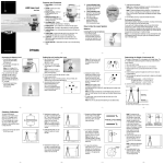
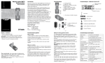
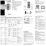
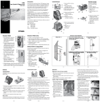
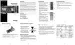
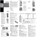
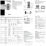
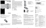
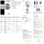
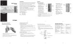
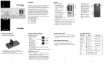
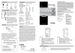
Introduction
LP20, LP40 Laser Pointer
User Guide
•
Features
Thank you for choosing the LP20 or LP40 Spectra Precision®
Laser from the Trimble® family of precision hand-held lasers. This
simple-to-use tool allows you to transfer points between the floor
and ceiling and to establish 90° points for laying out wall lines
and putting up wall partitions. You can also use the laser for
other applications where true plumb, square, and level setups
are required.
Installing/Removing the Batteries
1
2
3
CAUTION: The batteries should be removed when storing the
laser more than 30 days.
4
5
3
5
4
4
Before using the laser, be sure to read this operator’s manual
carefully. Included in it is information about setting up, using,
and maintaining the laser. Also included in this manual are
CAUTIONS and Notes. Each of these words represents a level
or danger or concern. A CAUTION indicates a hazard or unsafe
practice that could result in minor injury or property damage.
A Note indicates important information unrelated to safety.
3
5
1. Release the battery door using your fingers. Open the door.
2. Install/remove the 4 AA batteries.
6
Your comments and suggestions are welcome; please contact us at:
Trimble Construction Division
5475 Kellenburger Road
Dayton, Ohio 45424-1099 U.S.A.
Phone: (937) 245-5600
(800) 538-7800
FAX:
(937) 233-9004
Internet: www.trimble.com
Note: When installing the batteries, be sure to note the positive
(+) and negative (–) diagrams molded on the battery housing.
1. Power Button
4. Level Offset Mark
2. Power-Status LED
5. Plumb Offset Mark
3. Lens
6. Battery Housing
3. Close the battery door and latch it shut.
www.trimble.com
–2–
–3–
Setting Up the Laser and Transferring a Point
Setups attempted through glass or other material will affect the
accuracy of the laser.
–4–
0002-8210 Universal Accessory
3. Adjust the position of the
laser so that the down beam
is on the control point.
1 M (4 Ft) Marks
Elevations with 1/4–20
Tripod Mount
Columns with Strap or
Bungee Cord
Ceiling with 0002-1106
Ceiling Mount
Pipes/Conduit
72 mm
23/16 in
1. Press the power button. The green power-status LED lights to
show that the laser is on.
4. Locate the position of the
up beam and level beam.
Make a mark on the ceiling
and wall respectively.
CAUTION: Never look directly into the laser beam.
2. Place the laser on a flat surface. The laser must be within ±4° of
being level for it to self-level.
–5–
Plumbing a Wall
–6–
Specifications
1. Place the laser so that the
bottom feet are on the front
edge of the bottom track.
2. Press the power button.
3. Adjust the top of the
partition until the up
beam is on the front edge
of the top track.
Up Beam Accuracy*
+/– 6 mm @ 21 m (+/– 1/4 in. @ 70 ft)
Down Beam Accuracy*
+/– 1 mm @ 0.5 m (+/– 1/16 in. @ 2.5 ft)
Level Beam Accuracy*–LP40
+/– 6 mm @ 30 m (+/– 1/4 in. @ 100 ft)
Square Beam Accuracy*–LP40 +/– 6 mm @ 30 m (+/– 1/4 in. @ 100 ft)
Self-Leveling Range
±4° from level
Out-of-Level Indicator
Beam flashes
Working Range*
20–30 m (65–100 ft)
Laser Class
2
Laser Type
LP40–635 nm; LP20–650 nm
Beam Shape
Round
Battery Type
4 AA alkaline
Battery Life
40 hours (alkaline)
Low Battery Indicator
LED Blinking
Auto-Shutoff
1 hour (on/off selectable)
(Holding the power button
down for 3 seconds
enables auto-shutoff.)
Operating Temperature Range –10 °C to 45 °C (14 °F to 113 °F)
Size
12.0 x 11.0 x 6.5 cm (4.7 x 4.4 x 2.6 in.)
Weight
0.4 kg (0.9 lb)
*When operated within specified temperature range
–7–
–8–
Maintenance and Care
System Cleaning
You will get years of service from your laser by following the
maintenance and care recommendations in this manual. However
well the product is designed, mishaps do occur and the most
common problems associated with these are covered in the
following areas. Any damage to the laser caused by improper
maintenance and care voids the warranty.
For maximum performance and accuracy always keep the lenses
clean. When cleaning, apply very light pressure and use only a
good quality glass cleaner on a soft cloth to clean the exterior of
the laser and its lenses.
CAUTION: A dry cloth or abrasive organic cleaner could scratch
or damage these surfaces.
Handling Precautions
CAUTION: Do not submerge the laser.
When transferring the laser from a very low temperature to a
warmer environment or visa versa, always allow time for the laser
to reach the new temperature before using. Allowing this time is
especially important when transferring the laser from an extremely
heated/cold vehicle to the job site.
Storage
When you’re not using the laser, store it in its pouch/carrying case.
CAUTION: Do not store the laser in a wet pouch/carrying case.
If the pouch/carrying case gets wet, let it dry before storing the
laser in it.
CAUTION: The batteries should be removed when storing the
laser more than 30 days.
Battery Disposal
Some states and local areas have regulations regarding the disposal
of batteries. Be sure to dispose of discharged batteries properly.
–9–
– 10 –
– 11 –
– 12 –
Calibration
Checking Accuracy—Level
Before each use, be sure to check the pocket laser for signs of
damage. If the laser has been dropped or subjected to other rough
treatment, it should be checked for accuracy.
4. Rotate the laser 180° and
realign the down beam
over the reference mark on
the floor.
Distance Between Walls
1)
5. Locate the position of the
up beam on the ceiling,
which will be twice the
actual error, and make
a mark.
2. Place the laser so that
its down beam is over a
reference mark on the floor.
3. Locate the position of the
up beam on the ceiling and
make a mark.
8. Without changing the height of the laser, rotate it 180° to place
the beam near the mark on the first wall (step 3).
2)
Checking Accuracy—Plumb
1. Press the power button.
7. Adjust the laser’s height until the beam is superimposed over
the mark made in step 5.
9. Measure the vertical distance between the beam and the mark
made in step 3. If the measurement is greater than the values
shown below, the laser must be serviced at an authorized
service center.
3)
4)
1. In an area with at least 6 m (20 ft) between two parallel walls,
place the laser 50–75 mm (2–3 in.) from one wall, facing
the wall.
6. Measure the difference
between the two marks on
the ceiling, which will be
twice the actual error. If
the difference is more than
5 mm in 7.5 m (3/16 in.
in 25 ft), the laser must be
serviced at an authorized
service center.
3.0 mm (1/8 in.)
6.0 mm (1/4 in.)
8.0 mm (5/16 in.)
11.0 mm (7/16 in.)
6 m (20 ft)
12 m (40 ft)
18 m (60 ft)
24 m (80 ft)
2. Press the power button.
3. Locate the position of the level beam on the wall and make
a mark.
4. Rotate the laser 180° so that the laser faces the other wall.
5. Locate the position of the level beam on the wall and make
a mark.
6. Move the laser to the far wall, facing the wall.
– 13 –
– 14 –
Checking Level to Square Beam 90° Calibration
(LP40 only)
2. Set up the laser so that its
down beam is over point A.
Make sure the level beam
points toward the far end
of the room.
3. Mark a point (B) on the
floor at the center of
the room using a target
to transfer the level beam
location to the floor.
5. Move the LP40 to point B and align the level beam to point
C again.
6. Mark the location of the square beam (D) on the floor.
Note: To ensure accuracy, the distances from A to B, B to C,
and B to D should be equal.
Steps 1-4
Mark point A.
Set up laser
over A.
Mark points
B & C.
E A
X
D
7. Turn the LP40 90° so that the level beam aligns with point D.
8. Mark the location of the square beam (E) on the floor as close
as possible to point A.
B
X
Steps 5-6
9. Measure the distance between points A and E. If the
measurement is greater than the values shown below, the laser
must be serviced at an authorized service center.
Set up laser
over B.
Align to point C.
Mark point D.
Steps 7-8
Turn laser 90°
and align to D.
Mark point E.
– 16 –
Request for Service
Refer to the graphic for the location of the LP40 at each step and
for the location of the marks made at each step. All marks can be
made on the floor by placing a target in front of the level or square
beam and transferring the location to the floor.
1. Find a room at least
10 m (35 ft) long. Mark
a point (A) on the floor at
one end of the room.
– 15 –
C
Room length or distance
between points A and C
The 90° angle between the
level beam and square beam is out
of calibration if the distance between
points A and E is:
10 m (35 ft)
>9.0 mm (3/8 in.)
20 m (70 ft)
>18.0 mm (3/4 in.)
X
4. Mark a point (C) on the
far wall or transfer the level beam location to the floor.
– 17 –
Notice to Our European Union Customers
Our goal is to provide prompt and efficient service through
competent service dealers. To locate your local dealer or authorized
Trimble Service Center, contact our world centers listed below.
North America
Trimble Construction Division
5475 Kellenburger Road
Dayton, Ohio 45424-1099
U.S.A.
(800) 538-7800 (Toll Free)
+1-937-245-5600 Phone
+1-937-233-9004 Fax
Africa & Middle East
Trimble Export Middle-East
P.O. Box 17760
Jebel Ali Free Zone, Dubai
UAE
+971-4-881-3005 Phone
+971-4-881-3007 Fax
Asia-Pacific
Trimble Navigation
Australia PTY Limited
Level 1/120 Wickham Street
Fortitude Valley, QLD 4006
AUSTRALIA
+61-7-3216-0044 Phone
+61-7-3216-0088 Fax
Europe
Trimble GmbH
Am Prime Parc 11
65479 Raunheim
GERMANY
+49-6142-2100-0 Phone
+49-6142-2100-550 Fax
Latin America
Trimble Navigation Limited
6505 Blue Lagoon Drive
Suite 120
Miami, FL 33126
U.S.A.
+1-305-263-9033 Phone
+1-305-263-8975 Fax
– 19 –
Laser Safety
Warranty
The pocket laser uses a Class 2 laser, which complies with the
requirements based on the IEC825-1/EN60825 standards (Class
2 based on 21CFR 1041). This laser may be operated without the
need for any additional protective measures. Nevertheless, as with
the sun, care should be taken to avoid looking directly into the
light source.
Trimble warrants the Spectra Precision® Laser LP20 and LP40 to
be free of defects in material and workmanship for one year. This
warranty period is in effect from the date the system is delivered
by Trimble or its authorized Dealer to the purchaser, or is put into
service by a Dealer as a demonstrator or rental component.
Any evidence of negligent, abnormal use, accident, or any attempt
to repair equipment by other than factory-authorized personnel
Trimble certified or recommended parts, automatically voids the
warranty.
CAUTION: Never look directly into the laser beam.
Please keep the pocket laser out of the reach of children.
Trimble or its Authorized Service Center will repair or replace, at
its option, any defective part or components of which notice has
been given during the warranty period. A Warranty Registration
Card must be filled out properly and on file with Trimble Service
Department before warranty repair or replacement can be
approved. Travel and per diem expenses, if required, to and from
the place where repairs are made will be charged to the purchaser
at the prevailing rates.
– 22 –
To recycle Trimble WEEE,
call: +31 497 53 2430, and
ask for the “WEEE associate,” or
mail a request for recycling instructions to:
Trimble Europe BV
c/o Menlo Worldwide Logistics
Meerheide 45
5521 DZ Eersel, NL
– 20 –
Special precautions have been taken to ensure the calibration
of the laser; however, calibration is not covered by this warranty.
Maintenance of the calibration is the responsibility of the user.
The foregoing states the entire liability of Trimble regarding
the purchase and use of its equipment. Trimble will not be held
responsible for any consequential loss or damage of any kind.
This warranty is in lieu of all other warranties, except as set forth
above, including an implied warranty merchantability of fitness for
a particular purpose, is hereby disclaimed. This warranty is in lieu
of all other warranties, expressed or implied.
Customers should send products to the nearest Authorized Factory
Service Center for warranty repairs, freight prepaid. In countries
with Trimble Service Subsidiary Centers, the repaired products will
be returned to the customer, freight prepaid.
– 21 –
Recycling in Europe
China
Trimble Beijing
Room 2805-07, Tengda Plaza,
No. 168 Xiwai Street
Haidian District
Beijing, China 100044
+86 10 8857 7575 Phone
+86 10 8857 7161 Fax
www.trimble.com.cn
– 18 –
Additionally, items covered by the standard Trimble oneyear warranty are the accessories. All other components not
manufactured Trimble but sold as a part of the system, such
as tripods and grade rods, will carry a 90 days warranty or the
manufacturer’s warranty, whichever is greater.
For product recycling instructions and more information,
please go to: www.trimble.com/environment/summary.html
Trimble Construction Division
5475 Kellenburger Road
Dayton, Ohio 45424-1099
U.S.A.
+1-937-245-5600 Phone
www.trimble.com
– 23 –
© 2004–2005, Trimble Navigation Limited. All rights reserved.
Reorder PN 0002-0020 Rev. D (10/05)