1
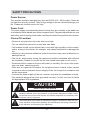
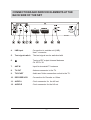
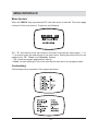
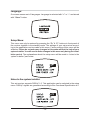
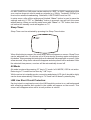
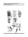
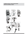
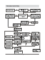
SR-26 User Guide SR-26 ANALOG SATELLIT RECEIVER • • • • • • • • • • • • • • • • • • 450 Pre-programmed channels (ASTRA, EUTELSAT/HOT BIRD, and other) 2 SCART connectors (TV and VCR/DECODER) OSD On-Screen-Display (English and German) Parental lock and favourites list Frequency range 920 – 2150 MHz LNB control via 14/18 volt, 22 kHz and DiSEqC 1.0 Stereo audio output via RCA/phono Stereo/Mono Infrared Remote control UHF modulator, channel 30-39 Last channel function / channel memory Volume level control for each program channel. Mute function Support for Ku and C band LNB power off in standby Sleep timer Dynamic noise reduction for better sound LNB line short circuit and overload protection CONTENTS GENERAL PROPERTIES ........................................................................................... 2 SAFETY PRECAUTIONS ............................................................................................ 3 Power Source: ................................................................................................... 3 Power Cord: ...................................................................................................... 3 Choice Of Location: .......................................................................................... 3 SATELLITE ANTENNA ............................................................................................... 4 PUTTING ON THE BATTERIES OF THE REMOTE CONTROL ........................................................................................... 4 CONNECTION OF YOUR TV WITH THE SATELLITE RECEVIER ................................ 4 Connection to the TV: ........................................................................................ 4 Putting into operation: ....................................................................................... 4 Tuning your TV to the Sat-receiver: ................................................................... 5 Scart socket: ...................................................................................................... 5 Audio Output socket: ......................................................................................... 5 FUNCTIONS ON THE FRONT PANEL OF THE RECEIVER .......................................... 6 1. STANDBY : ............................................................................................ 6 2. BUTTONS : ................................................................................ 6 3. CHANNEL DISPLAY : ........................................................................... 6 CONNECTIONS AND SERVICE ELEMENTS AT THE BACK SIDE OF THE SET .......... 7 REMOTE CONTROL FUNCTIONS .............................................................................. 8 MENU INTERFACE ..................................................................................................... 9 Menu System: ................................................................................................... 9 Customizing: ..................................................................................................... 9 Installation: ...................................................................................................... 11 Language: ....................................................................................................... 12 Setup Menu: .................................................................................................... 12 Notes to the system installer: ......................................................................... 12 Sleep Timer: .................................................................................................... 14 AV Mode: .......................................................................................................... 14 LNB Line Short Circuit Protection: .................................................................. 14 CONNECTION OF THE SAT-RECEIVER WITH A SCART CABLE .................................................................................... 15 CONNECTION OF THE SAT-RECEIVER WITH RF ANTENNA CABLE ............................................................................. 16 TROUBLE SHOOTING ............................................................................................. 17 TECHNICAL SPECIFICATIONS ................................................................................ 18 GENERAL ....................................................................................................... 18 VIDEO .............................................................................................................. 18 AUDIO ............................................................................................................. 18 RF .................................................................................................................... 18 RF MODULATOR ............................................................................................. 19 SR REMOTE CONTROL ................................................................................. 19 LNB POWER SUPPLY .................................................................................... 19 -1- GENERAL PROPERTIES 1) User-friendly OSD menu control (2 languages) 2) DiSEqC 1.01 3) 2 Scarts (TV, VCR/Decoder) 4) Keypad control 5) Multi-functional remote control 6) Horizontal/vertical polarity switching(18/13V) 7) 0-22 kHz switching 8) Toneburst A/B switching for dish selection 9) C/Ku Band Switching 10) Video Search 11) Stereo sound 12) Volume level control for each program channels 13) Audio Mute 14) 15 pre-set plus 1 user adjustable audio modes 15) 50µs,75µs, FLAT audio de-emphasis 16) 7 Audio Bandwidths (80/110/130/180/230/380/500kHz) 17) Dynamic noise reduction for better sound 18) System switching (TV/RADIO/DECODER) 19) PAL/MAC/DEEMPHASIZED Video Selection for Decoder 20) 920-2150 MHz video frequency band, 5.00-9.00 MHz audio frequency band 21) Video contrast switching (50 steps) per channel 22) AV mode 23) VCR play in standby mode 24) Video Mute selection for dish installation 25) Sleep Timer 26) Program Copy 27) Program lock 28) Program skip 29) Selectable LNB Local Oscillator frequency (8 presets) 30) Last function / channel memory 31) LNB power off in standby mode 32) LNB line short circuit and overload protection by software 33) Wide range SMPS. 1 DiSEqC is a Trademark of Eutelsat -2- SAFETY PRECAUTIONS Power Source: The receiver should be operated only from an 85-265 V AC, 50 Hz outlet. Please do not open the cover by yourself. There is high voltage in the set, which will danger your life. Please ask closest service for help. Power Cord: The power supply cord should be placed so that they are not likely to be walked on or pinched by items placed upon them or against them. Pay particular attention to cord where they enter the plug, power outlet, and the point where they exit from the receiver. Choice Of Location: Please do not place the set under direct sun light. The set should be placed on a solid and safe base. The location should not be selected as a room with high humidity, as the condensation, arising in the kitchen for example, may cause malfunction or damage the set. Heating or other thermal radiations under the set also may cause malfunction or damage the set. The hot air, which arises during the operation should be ventilated with sufficient air circulation. Please do not put the set into closed areas and do not cover it. Please avoid the contact of the set with water or humidity. Do not put into operation near bath, swimming pools. Take care for a good air circulation. Do not place the set on beds, sofas, carpets or similar surface otherwise the air supply of the set though the ventilation-slot will be interrupted. Connect the power supply of the sat- receiver only after the installation is ready. The parabolic antenna has to be grounded correctly. For this you have to follow the appropriate VDE regulations. CAUTION RISK OF ELECTRIC SHOCK The lightning flash with arrowhead symbol, within an equilateral triangle, is intended to alert the user to the presence of uninsulated "dangerous voltage" within the product's enclosure that may be of sufficient magnitude to constitute a risk of electric shock of persons. The exclamation point within an equilateral triangle is intended to alert the user to the presence of important operating and maintenance (servicing) instructions in the literature accompanying the appliance. -3- SATELLITE ANTENNA To have an excellent function of the sat-receiver, it is necessary to install the antenna correctly. Please avoid under all conditions to have a short circuit at the antenna cable conductor (LNB receiver). The sat-receiver is equipped with a LNB short-circuit protection. PUTTING ON THE BATTERIES OF THE REMOTE CONTROL First open the battery cover on the underside of the remote control. Put on both batteries 1.5Volt (R03/AAA) referring to the imprinted symbols (+/-) in the battery case and put on the battery cover again. While using the remote control, direct it towards the front side of the receiver. If the remote control do not work or the chosen function could not be made, the batteries are most probably exhausted and they should be replaced as soon as possible. Please use only the leak proof batteries. It is the best to take out the batteries from remote unit in case you wouldnt use the remote control unit for long time. CONNECTION OF YOUR TV WITH THE SATELLITE RECEVIER Connection to the TV: 1. Connect your terrestrial antenna to the ANT IN signed socket of the satellite receiver. 2. Connect an antenna cable between the TV OUT signed socket of the satellite receiver and the antenna socket of the TV, as it is used for video recorders. 3. Carefully plug in the connector of the satellite antenna cable to the LNB INPUT (920-2150MHz) signed socket of the satellite receiver. Putting into operation: Be sure that you put through all the cable connection. After plugging in the mains supply of the set to the mains supply, a red light will be seen on the front panel. Then, user can turn on the receiver by pressing standby button on remote control or keypad. The red light in front panel will disappear. -4- Tuning your TV to the Sat-receiver: Put the switch Test/TV on the backside of the set to position TEST. The signal of the sat-receiver is tuned for channel 38(UHF) ex factory. Turn on your TV and tune it with the channel search (UHF area) to the test signal. The test signal exists of two vertical white stripes on black background. Memorize this tuning on an unused program on your TV. You can later receive the satellite on this program. If needed, please use the operation manual of your color TV. Remark: If your channel 38 is used by a program, which you receive via an antenna or another connected set, for example a video recorder, you can tune on the output of the receiver between 30-39 UHF. Turn with a small screwdriver carefully the signed output on the back of the set. With this process you can change the channel of the starting signal of the sat receiver. In this way you can tune channels 30-39. Tune again your TV for the RF signal and memorize this adjustment. Scart socket: When you additionally connect your set with a scart cable, the satellite programs will be directly fed in the TV, respectively the video receiver, as far as you have chosen the AV channel of these sets. The picture and sound quality will be improved better. During the operation over the scart cable there is no special adjustment needed. Audio Output socket: The audio sockets are used to connect the sat-receiver to a hi-fi set. So you can listen to the TV sound or one of the numerous radio stations via your set or respectively record on a cassette recorder. -5- FUNCTIONS ON THE FRONT PANEL OF THE RECEIVER 1. STANDBY : If the receiver is in the standby position, you can turn on or off with this button. (last tuned program will be shown). 2. BUTTONS : Modification on selected pages aremade by these buttons. These buttons can also be used to exit standby. 3. LED DISPLAY : The 4 digit LED display is for displaying the program numbers. -6- CONNECTIONS AND SERVICE ELEMENTS AT THE BACK SIDE OF THE SET 79287 $8',2 79 7(67 '(&2'(59&5 /()7 $&9 +] 5,*+7 $17,1 4. LNB Input Connection to outside unit (LNB). Use F connector. 5. Test signal switch The test signal can be switched with Tuning of RF output channel between Ch 30-Ch 39 6. 7. ANT IN Input for terrestrial TV antenna 8. TV OUT Antenna connector to the TV. 9. TV SCART Audio and Video connection socket to the TV. 10. DECODER-VCR Connection for Decoder or Video. 11. AUDIO L Cinch connector for the hifi set. 12. AUDIO R Cinch connector for the hifi set. -7- REMOTE CONTROL FUNCTIONS 13. STANDBY : The receiver can be turned on or off with this button. 14. (MUTE) : For the interruption of the sat-receiver sound (Mute). 15. 0-9 BUTTONS : For the direct selection of the program number, video and audio frequency. 0 key also has an AV function. 16. - : Decrease the volume or change the positions among the program number, name, frequency of LNB, video and audio. 17. MENU : To enter the top menu. 18. This button has no function. 19. TV : To exit menu page and return to the program without saving. 20. STORE : Button to store the changes made in menus. 21. SLEEP TIMER : To adjust the time that your receiver will turn off automatically. 22. P+ : Increase program number, and move upwards in the menu. 23. + : Enter sub-menu, increase the volume, video and audio frequency or change the menu parameters. 24. P- : Decrease program number and move downwards in the menu. 25. This button has no function. -8- MENU INTERFACE Menu System: When the MENU key is pressed on R/C, the main menu is entered. This menu page consists of four sub-menus. These are as following; P+, P- are used to move up & down in the main menu as the other pages. + or - is used to enter the sub-menus in the main menu. Exiting from this menu is only made by the TV, Store and Standby buttons. TV to exit to program page without saving. Store to save settings in all of the sub-menus and return the program mode. Customizing: Customizing menu consists of two pages as below. -9- In LNB NO line, 8 or 16 different LNB configurations (corresponding to the LNB NO line in the installation page) can be chosen by using +,- (8 for DiSEqC OFF, 16 for DiSEqC ON mode). At every LNB NO changing, the video frequency is driven according to selected LNB frequency. User can switch to second customizing page by pressing P+ in this line. In PR. FREQ. line, the program frequency can be entered in two different ways: i) Direct access. For example to enter 10921MHz just press 1-0-9-2-1 buttons one by one. ii) Increasing/decreasing frequency with 1 MHz steps using + ,- buttons. By pressing continually to + or -, video search begins. Video search stops automatically after tuning to another program or until the end of frequency band if there is no program after/before the frequency that video search began. User can exit video search manually by pressing TV button only. In AUDIO NO line, audio frequency can be chosen among 15 preset audio frequencies or user-defined 16th mode. The user can change the audio frequency and mode only when audio no is 16. While the other 15 numbers are selected, user cant reach these lines by pressing P- button in this line. At the 16th audio type, in the AU. MODE line, Stereo/Mono is switched for this audio frequency. In the AU. FREQ. line, the audio frequency is changed like program frequency. The range for audio frequency is between 5.00 -9.00 MHz. In the SYSTEM line, select TV to watch a channel RADIO to listen to audio only with blue background on screen. A musical note symbol will appear in program page if a program is set to radio. PAL DEC. to watch a pay TV channel that can be only watched by PAL decoder MAC DEC. to watch a pay TV channel that can be only watched by a D2MAC decoder. DEEMPH. to watch a pay TV channel that can be only watched by a D2MAC decoder. In this line, user can switch to second customizing page by pressing P-. At the DEEMPH. line, 3 different de-emphasis modes can be selected. These are FLAT, 50µs, 75µs. At the AUDIO BW line, 7 different audio bandwidth modes (80/110/130/180/ 230/380/ 500kHz) can be selected. At theDNR line, Dynamic Noise Reduction can be switched as ON/OFF with +, - buttons. CONTRAST line is used to adjust the contrast level of programs from 1 up to 50 with +, - buttons. In PR. LOCK line, by selecting YES with +, - buttons, parental lock is set. The user will see blue background even if there is a video signal. And a lock character will appear under the program number after exiting the menu. - 10 - To skip a program, PR. SKIP line is used. If it is enabled, the user can not reach this program with P+, P- buttons. Only direct accessing is enabled to watch the skipped program. TV is used to return without saving, Store button to return to the program mode with saving for selected channel number. To store the customizing page, Store button is pressed and then program number begins to flash. +,- or 0-9 buttons are used to change channel number. After entering the program number Store button is pressed again to save the program settings to this program. Installation: This page depends upon the DiSEqC mode selection in the setup menu. Setup menu and the other modes of this page will be explained later in notes to the system installer part. While DiSEqC is OFF installation menu seems like this: In this page, technical specifications for 8 different LNBs are defined. In the LNB FREQ. line, for each LNB, Local Oscillator frequency can be selected by using +, - buttons from 8 preset values: 9750, 10000, 10600, 10750, 11000, 11250, 11475 MHz for Ku Band and 5150MHz for C Band. In POL line, polarity is changed as vertical or horizontal by +,-. 22 kHz can be switched for each LNB. 22 kHz can be used either for dish switching (with a 22kHz switch) or Universal LNB frequency band switching. If DiSEqC is ON in setup menu, 22kHz can only be used for frequency band switching for universal LNBs. TONEBURST signal can be used for each LNB to select dishes with a toneburst switch. - 11 - Language: On screen menus are in 2 languages. Language is selected with + or - and stored with Store button. Setup Menu: This menu can only be entered by pressing the P+ & P- buttons in front panel of the receiver together in the standby mode. The settings of your sat receiver according to the application can be made in this menu. Factory setting of this menu will be as below. Please do not make any changes in this menu without the help of your system installer. You will need to make changes in this menu only during the installation period. The explanations about the setup menu will be made in notes to the system installer part below. Notes to the system installer: This sat receiver supports DiSEqC 1.0. This application can be selected in the setup menu. DiSEqC signals are generated according to Bus Functional Specification 4.2. - 12 - In the DiSEqC line, DiSEqC mode can be changed to OFF/ON. While DiSEqC is switched to OFF, REPEAT automatically changes to 0, no DiSEqC signals are generated and the installation menu is as in installation page description. The user can not reach REPEAT line in this mode. If any DiSEqC device will be used (e.g. DiSEqC 1.0 or 2.0 switch, multiswitch or LNB), DiSEqC mode must be selected as ON to communicate with these devices. In this mode, DiSEqC signals are sent with the analog 13/18V, 22kHz and toneburst signals. The installation menu changes like this in DiSEqC ON mode. LNB Numbers can be increased up to 16 while DiSEqC is ON. Satellite Position is combination of Position and Option as below. DiSEqC device address is chosen as 00H to support all devices. In REPEAT line, repeat number of DiSEqC signals can be selected. This number corresponds to the number of cascaded DiSEqC accessories in your sat system. For example if there is only one DiSEqC switch (or multiswitch), repeat number may be 0. If there is a DiSEqC switch (or multiswitch) and a DiSEqC LNB, repeat number must be 1. In VIDEO MUTE line Video Mute function can be enabled or disabled. When VIDEO MUTE is OFF, there will be no blue background even if there is no video signal or video signal is too bad. This mode is recommended during dish installation. When VIDEO MUTE is ON, there will be blue background if there is no video signal or video signal is too bad. This mode is recommended after installation procedure has finished. - 13 - In LNB POWER line, LNB power can be switched to OFF in SMATV applications that your receiver does not need to send any signals (e.g. 22kHz, Toneburst, DiSEqC) to receive the satellite broadcasting. Otherwise, LNB POWER must be ON. In setup menu, after all the settings are finished Store button is used to save the settings and exit. If TV or Standby button is pressed, user will exit this menu without saving. When you exit the setup menu with Store or TV button, last channel before the standby mode will appear on TV. Sleep Timer: Sleep Timer can be activated by pressing the Sleep Timer button. When this button is pressed, the sleep timer value will appear on screen. Sleep Timer can be adjusted from 15 minutes up to 90 minutes by pressing again and again to this button. Stop pressing this button when the desired value appears on screen. After a few seconds, sleep timer value will disappear and sleep timer will be activated. After the selected time passes, receiver will be automatically turned off. AV Mode: AV mode is entered by pressing 0 key in TV mode. In AV MODE, OSD is not active. Returning to TV mode can be done by 1-9 keys. While receiver is in standby mode, connecting and playing VCR (pin 8 should be high) can be done automatically. Returning to TV mode can be done by standby key. LNB Line Short Circuit Protection: If a short circuit or overload occurs in the LNB line while receiver is on, red background with a flashing satellite dish symbol in the middle will appear on the screen. This screen will disappear when short circuit problem is solved. - 14 - CONNECTION OF THE SAT-RECEIVER WITH A SCART CABLE - 15 - CONNECTION OF THE SAT-RECEIVER WITH RF ANTENNA CABLE - 16 - TROUBLE SHOOTING - 17 - TECHNICAL SPECIFICATIONS GENERAL LNB input .................................................. : 1 Supply Voltage .......................................... : 85-265 V AC, 50Hz Program Place ......................................... : 450 channels Input Frequency ........................................ : 920-2150 MHz Carton Size (mm) ..................................... : 300x65x150 Weight ....................................................... : 1 kg VIDEO Signal ........................................................ : Clamped video signal, with negative synchronization Signal standard ........................................ : PAL, CCIR 405, 625 scanning lines Output impedance .................................... : 75 Ohm Bandwidth ................................................. : 500Hz-5,5 MHz Output level ............................................... : 1 Vpp Tune .......................................................... : PLL AUDIO Audio Carrier ............................................ : Mono 5,0-9,00 MHz Stereo L 5,0-9,00 MHz Stereo R 5,0-9,00 MHz De-emphasis ........................................... : 50 µs, 75 µs, FLAT Tune .......................................................... : PLL Output Conn. ............................................ : Scart & phonojack (L/R) RF Input level .................................................. : -65dBm to -30dBm Input impedance ...................................... : 75 Ohm IF-Frequency ............................................. : 479,5 MHz Bandwidth ................................................. : 27 MHz - 18 - RF MODULATOR UHF output conn. ...................................... : IEC male ANT input conn. ........................................ : IEC female Standard ................................................... : PAL G Output channel ......................................... : Channel 30-39 UHF (Channel 38preprogrammed) SR REMOTE CONTROL Range ....................................................... : approx. 6m Batteries ................................................... : 2x1.5V Micro (R-03/AAA) LNB POWER SUPPLY Vertical ...................................................... : 13 Volt Horizontal .................................................. : 18 Volt Max. Output Current : ................................ : 400 mA (Short-circuit protected ) - 19 - SR-26 User Guide - 20 - SR-26 User Guide Triax A/S Bjørnkærvej 3 DK-8783 Hornsyld www.triax.com - 21 -