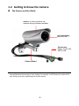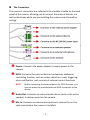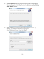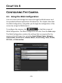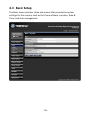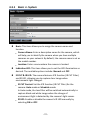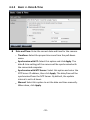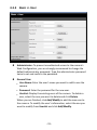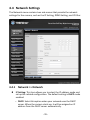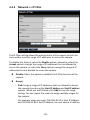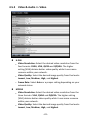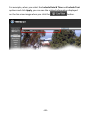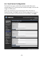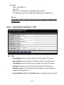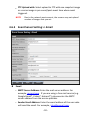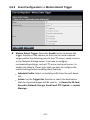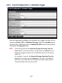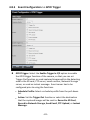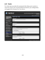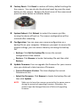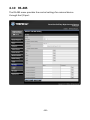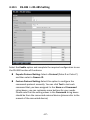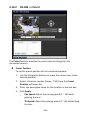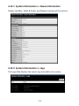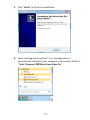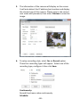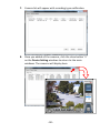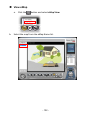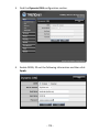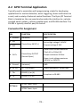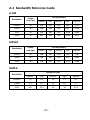
1
P REFACE Thank you for purchasing the TV-IP322P SecurView™ Outdoor PoE Megapixel Day/Night Internet Camera, a standalone system that can be connected directly to an Ethernet or Fast Ethernet network. The camera is equipped with a 2-megapixel CMOS sensor, allowing you to capture high quality image with the resolution of up to 1280 x 1024. Additionally, the camera features the IR (Infrared) LEDs and ICR function (IR Cut Filter). The ICR function enables the camera to capture the clear image under sunlight and increase the amount of light for IR LEDs in the dark by changing the filter automatically. The camera also provides the audio and microphone ports, allowing you to transfer sound from/to the camera. Compared to the conventional PC Camera, this camera features a built-in CPU and web-based solutions that can provide a cost-effective solution to transmit the real-time high-quality video images and sounds synchronously for monitoring. The camera can be managed remotely, so that you can use a web browser to access and control it from any desktop/notebook computer over the Intranet or Internet. Compliant with IEEE802.3af PoE (Power over Ethernet) standard, the camera provides you with more flexibility of camera installation according to your application. The camera can be powered by the Ethernet, so that you can place the camera anywhere without a power outlet supported. The trouble-free installation procedures and web-based interface allow you to integrate it into your network fast and easy. With comprehensive applications supported, the Internet camera is your best solution for remote monitor, high quality, and high performance video images. -1- This Advanced Installation Guide provides you with the instructions and illustrations on how to use your camera, which includes: Chapter 1 Introduction to Your Camera describes the features of the camera. You will also know the components and functions of the camera. Chapter 2 Hardware Installation helps you install the camera according to your application environment. You can use this camera at home, at work, at any where you want. Chapter 3 Accessing the Camera lets you start using your camera without problem. The camera can be set up easily and work within your network environment instantly. Chapter 4 Configuring the Camera guides you through the configuration of the camera using the Web browser on your PC. Chapter 5 Using SecurView™ Pro shows you the detail instructions on operating SecurView™ Pro software. Chapter 6 How to Access the Camera Behind a Router provides the instruction how to setup your DDNS. Chapter 7 Appendix provides the specification of the camera and some useful information for using your camera. NOTE The illustrations and configuration values in this guide are for reference only. The actual settings depend on your practical application of the camera. NOTE All trademarks and logos are the property of the respective trademark owners. -2- Contents PREFACE CHAPTER 1 INTRODUCTION TO YOUR CAMERA 1.1 1.2 1.3 1.4 CHECKING THE PACKAGE CONTENTS ............................................. 5 GETTING TO KNOW THE CAMERA ................................................. 6 FEATURES AND BENEFITS ............................................................ 9 SYSTEM REQUIREMENT ............................................................ 12 CHAPTER 2 HARDWARE INSTALLATION 2.1 2.2 2.3 2.4 ASSEMBLING THE CAMERA MOUNTING BRACKET .......................... 14 MOUNTING THE CAMERA ......................................................... 14 INSTALLING THE MEMORY CARD ................................................ 15 APPLICATIONS OF THE CAMERA.................................................. 16 CHAPTER 3 ACCESSING THE CAMERA 3.1 3.2 3.3 USING IP SETUP ...................................................................... 17 ACCESSING TO THE CAMERA ...................................................... 22 CONFIGURING THE IP ADDRESS OF THE COMPUTER ....................... 25 CHAPTER 4 CONFIGURING THE CAMERA 4.1 4.2 4.3 4.4 4.5 4.6 4.7 USING THE WEB CONFIGURATION .............................................. 26 USING SMART WIZARD ............................................................ 27 BASIC SETUP .......................................................................... 30 NETWORK SETTINGS ................................................................ 35 SETTING UP VIDEO & AUDIO ..................................................... 41 EVENT SERVER CONFIGURATION ................................................ 49 MOTION DETECT..................................................................... 57 -3- 4.8 4.9 4.10 4.11 4.12 EVENT CONFIGURATION ........................................................... 58 TOOLS ................................................................................... 64 RS-485................................................................................. 66 SETTING UP THE SD CARD......................................................... 70 INFORMATION ........................................................................ 72 CHAPTER 5 SECURVIEW™ PRO SOFTWARE 5.1 5.2 INSTALLATION ......................................................................... 75 USING SECURVIEW™ PRO ........................................................ 78 CHAPTER 6 Ho w to a c c es s th e ca m er a b eh in d a R o u t er A p p en d i x A.1 A.2 A.3 A.4 SPECIFICATION ...................................................................... 117 GPIO TERMINAL APPLICATION ................................................ 119 BANDWIDTH REFERENCE GUIDE............................................... 120 GLOSSARY OF TERMS ............................................................. 121 Li mi t ed Wa r r a n ty -4- C HAPTER 1 INTRODUCTION TO YOUR CAMERA 1.1 Checking the Package Contents Unpack the package and check the items contained in the package carefully. You should have the following: 1 x TV-IP322P 1 x Multi-Language Quick Installation Guide 1 x CD-ROM (Utility & User’s Guide) 1 x Desiccant ** 2 x GPIO Connector 1 x Spiral Cable Wrap 1 x Camera Mounting Bracket Kit* 1 x Power Adapter (12V DC, 1.5A) NOTE * Once any item contained is damaged or missing, contact the authorized dealer of your locale. The provided screws included: (1) screws and washers for assembling the camera shield; (2) expansion screws for mounting the camera to the wall. ** The camera provides two packs of desiccant: one pack is pre-installed inside the camera compartment before shipment; the extra pack is provided for replacement while you open the back cover in the future. -5- 1.2 Getting to Know the Camera The Camera and the Shield Shield* is used to protect the camera during inclement weather. Lens Assembly with IR LEDs Connectors Power, Audio, Mic, GPIO, LAN Camera Stand * There are various positions of screw hole on the shield, allowing you to move the shield forward/backward according to your needs. For example, it will protect the camera lens well during rainy day by adjusting the shield forward. -6- The Connectors The camera's connectors are collected into a bundle of cable on the back panel of the camera, allowing you to connect the external devices in a well-ordered way while you are installing the camera onto the wall (or ceiling). Power: Connects the power adapter to supply power to the camera. GPIO: Connects the external device that features additional controlling function, such as motion detection, event triggering, alarm notification, and a variety of external control functions. NOTE Before connecting the external device for GPIO function, you have to attach the provided external GPIO connectors to the device. Audio Out: Connects an external audio device (such as the active speaker) to deliver sound via the camera. Mic In: Connects an external microphone to receive the on-thespot sound where the camera is installed. -7- LAN: Plugs the provided Ethernet cable to connect to your local area network (LAN). The LAN port of the camera supports the NWay protocol so that the camera can detect the network speed automatically. -8- 1.3 Features and Benefits H.264/MPEG4/MJPEG Multi-codec Supported The camera provides you with excellent images by the H.264/MPEG4/ MJPEG multi-codec selectable technology, allowing you to adjust image size and quality, and bit rate according to the networking environment. High Resolution Surveillance Equipped with a megapixel CMOS sensor, the high performance camera is designed for your professional surveillance and security applications. The image resolution is up to 1280 x 1024. In addition, the minimum illumination of the sensor is 0 lux, providing a truly day & night functions that allows you to capture image even in low-light conditions. Multiple Profiles Supported The camera supports multiple profiles simultaneously, so that you can separately set up different image settings (such as image quality and frame rate) for the video types of the camera: H.264, MPEG4, MJPEG, and 3GPP. Flexible Audio Capability The camera allows you to connect the external microphone to receive on-the-spot audio via the Internet, allowing you to monitor the on-site voice. In addition, you can connect an external active speaker to the camera to speak through the camera (supporting mono audio only). Supports RTSP The camera supports RTSP (Real Time Streaming Protocol), which is a technology that allows you to view streaming media via the network. You can view the real-time video with the Quick Time player or RealPlayer. To view the real-time streaming image on your computer, open the Web browser and enter the RTSP link: rtsp://(IP address of the camera)/mpeg4 -9- Remote Control Supported By using a standard Web browser or the bundled SecurView™ Pro software application, the administrator can easily change the configuration of the camera via Intranet or Internet. In addition, the camera can be upgraded remotely when a new firmware is available. The users are also allowed to monitor the image and take snapshots via the network. I/O Connectors and RS-485 Provided The I/O connectors (IN/OUT) of the camera provide the physical interface to send and receive digital signals to a variety of external alarm devices (such as motion detection, event triggering, alarm notification, and a variety of external control functions). The pins TX+ & TX- of the I/O connectors are used for RS-485 data transmission, which allow you to connect a special featured device (such as an external camera stand with rotation function) and then configure the settings and control the device from the GPIO Trigger window of Web Configuration. Multiple Platforms Supported The camera supports multiple network protocols, including TCP/IP, SMTP e-mail, HTTP, and other Internet related protocols. Therefore, you can use the camera in a mixed operating system environment, such as Windows 7, Vista and XP. Multiple Applications Supported Through the remote access technology, you can use the cameras to monitor various objects and places for your own purposes. For example, babies at home, patients in the hospital, offices and banks, and more. The camera can capture both still images and video clips, so that you can keep the archives and restore them at any time. IR LEDs and IR CUT Filter Supported The IR LEDs around the lens assembly enables the camera capture image even in the dark environment. The night vision distance of the IR LEDs is up to 20M. The IR CUT Filter helps the camera increase the amount of light for IR LEDs by changing the filter - 10 - automatically. This allows the camera to capture clear image whenever the environment light changed. PoE Supported PoE (Power over Ethernet) standard enables the camera to be powered by the Ethernet, which simplifies your surveillance system by eliminating the need of power outlet. The PoE camera features both stability and security, providing a cost-saving solution to your application of Internet camera. Please make sure that you remove the power adapter when the camera power is supplied through PoE. - 11 - 1.4 System Requirement NOTE: Networking LAN 10 Base-T Ethernet or 100Base-TX Fast Ethernet; Auto-MDIX. PoE IEEE 802.3af PoE Accessing the Camera using Web Browser Platform Microsoft® Windows® 7/Vista/XP CPU Intel Pentium III 800MHz or above RAM 512MB Resolution 800x600 or above User Interface Microsoft® Internet Explorer® 6.0 or above Accessing the Camera using SecurView™ Pro Platform Microsoft® Windows® 7/Vista/XP Resolution 1024 x 768 or above Hardware Requirement: 1 ~ 8 cameras Intel Core 2 Duo; 2GB RAM 9 ~ 32 cameras Intel Core 2 Quad; 4GB RAM It is higher recommended that using a high performance computer to monitor multiple cameras. - 12 - C HAPTER 2 HARDWARE INSTALLATION - 13 - 2.1 Assembling the Camera Mounting Bracket Assemble the sun visor and camera mounting bracket to the camera by using the provided screws and washers, and then the camera can be mounted on the wall (or ceiling) securely through the three screw holes on the base of the holder. Adjust the camera position Once you have mounted the camera to the wall (or ceiling), you need to adjust the camera position to focus on the location where you want to monitor. You can adjust the camera position easily by using the swivel ball on the camera holder. 2.2 Mounting the Camera The expansion screws in the package are used to mount the camera on the wall (or ceiling). The following illustration provides one example of the camera installation. You can mount the camera flexibly according to your outdoor surveillance application. a. Place the bracket against the wall. Mark the three holes with a pencil. b. Drill holes for the provided screws anchors at each marked position. c. Align the mounting bracket with the screw anchors, and then use the provided screws to secure it. d. Secure the camera to the mounting bracket. e. Adjust the swivel on the mounting bracket to desired position. Waterproofing The camera is designed featuring waterproof. However, you need to protect the connectors from water soak. For example, you can tape the - 14 - junction points of the connectors while you connect the cables or purchase a weatherproof cable/power cord protector. 2.3 Installing the Memory Card The camera provides a SD card slot that allows you to install the memory card (not included in the package) to store files. To install the memory card: 1. Remove the back cover of the camera by unscrewing the three screws. 2. Locate the SD card slot inside the camera, and then insert the memory card into the slot. 3. Replace the back cover and then screw the three screws. - 15 - 2.4 Applications of the Camera The camera can be applied in multiple applications, including: Monitor local and remote places and objects via Internet or Intranet. Capture still images and video clips remotely. Upload images or send email messages with the still images attached. The following diagram explains one of the typical applications for your camera and provides a basic example for installing the camera. NOTE The camera’s connectors are not waterproof. Please have the connectors protected by waterproof housing. - 16 - C HAPTER 3 ACCESSING THE CAMERA 3.1 Using IP Setup The camera comes with a conveniently utility, IP Setup, which is included in the Installation CD-ROM, allowing you to search the camera on your network easily. 1. Insert the Installation CD-ROM into your computer’s CD-ROM drive to initiate the Auto-Run program. - 17 - 2. Click the IP Setup from the Auto-Run menu screen. Then IP Setup Wizard will appear. Click “Next” when the Welcome to the IPSetup Setup Wizard appears. 3. Click “Browse” to choose the desired destination location. By default, the destination location is C:\Program Files\TRENDnet\IPSetup. Then Click “Next”. - 18 - 4. Click “Next” to confirm the IPSetup software to be installed to the computer. 5. When the Installation Complete window appears, click “Finish”. - 19 - 6. After installing the IPSetup utility, the application is automatically installed to your computer, and creates a folder in “Start \Program\TRENDnet\IPSetup”. 7. Click Start > Programs > TRENDnet > IPSetup, and then click IPSetup 8. The IPSetup window will appear. It will search the Camera within the same network. Camera Display Area - 20 - - Camera Display Area: It shows the connected camera(s) within the same network. By default, the IP setting on the Camera is set up DHCP. If you have DHCP server, the camera will automatic get the IP address from DHCP server. If you do not have DHCP server on your network, it will show the default IP as 192.168.10.30. Double click the IP address; it will link to Camera’s Web Configuration page. - Change IP: Click this button to bring up the following window. It allows you to change the IP Address. You can select either Static IP or click DHCP. Then, enter the Administrator ID & password. By default ID/password is: admin. When complete, click “Change”. - Search: Click this button to search the connected camera within the network. - Exit: Click this button to exit the program. - 21 - 3.2 Accessing to the Camera By default, the IP setting on the camera is set to DHCP. It is recommend to use IPSetup to find the camera’s IP address. Once you find the IP address of the camera, click Link to access the camera’s web page. TIP If the camera cannot get the IP address from DHCP server, you can access the camera by manually entering the default IP address: 192.168.10.30 When the login window appears, enter the default User name (admin) and password (admin) and press OK to access to the main screen of the camera’s Web Configuration. NOTE If you are the first time to access the camera, you will be asked to install a new plug-in for the camera. Permission request depends on the Internet security settings of your computer. Click Yes to proceed. - 22 - The Main screen will appear as below: The Main screen of the Web Configuration provides you with the useful information and functions, including: Live View/Setup Switch: Click the details, see Chapter 4. button to configure the camera. For Click the button to return to the Main screen to view the live view image. Compression Buttons: Select to transmit and record the video using H.264, MPEG4 or MJPEG compression. Function Buttons: Use these buttons to control the audio, video, and trigger functions. Manual Record allows you to record and save a video clip. - 23 - Snapshot allows you to capture and save a still image. Browse allows you to assign the destination folder to store the video clips and still images. Talk allows you to speak out through the camera. Please note only one user is allowed to use this function at a time. Listen allows you to receive the on-site sound and voice from the camera. Trigger Out allows you to trigger on/off the GPIO output manually. Multicast allows you to change the camera’s transmission type between multicast/unicast. Live View Image: Displays the real-time video image of the connected camera. The compression mode is displayed above the Live View image. Zoom Buttons: Click the zoom buttons to zoom in/out the live view image. Camera Information – Display the camera’s location and the current date & time. The information can be modified in the Web Configuration. NOTE If your computer use Microsoft® Windows® 7/Vista platform, you may not find the recorded files that are saved by Snapshot or Manual Record. You need to disable the protected mode of Security in the IE Browser through the following steps: Please follow the below Steps: 1. Open IE Browser 2. Select ToolsInternet Options 3. Select Security 4. Uncheck the ”Enable Protected Mode” then press OK - 24 - 3.3 Configuring the IP Address of the Computer If you are failed to access to the camera, please check the IP address of your computer. When you connect the camera to your computer directly to proceed with configuration of the camera, you need to set up the IP addresses to be in the same segment for the two devices to communicate. 1. On your computer, click Start > Control Panel to open the Control Panel window. 2. Double-click Network Connection to open the Network Connection window. 3. Right-click Local Area Connection and then click Properties from the shortcut menu. 4. When the Local Area Connection Properties window appears, select the General tab. 5. Select Internet Protocol [TCP/IP] and then click Properties to bring up the Internet Protocol [TCP/IP] Properties window. 6. To configure a fixed IP address that is within the segment of the camera, select the Use the following IP address option. Then, enter an IP address into the empty field. The suggested IP address is 192.168.10.x (x is 1~254 except 30), and the suggested Subnet mask is 255.255.255.0. 7. When you are finished, click OK. - 25 - C HAPTER 4 CONFIGURING THE CAMERA 4.1 Using the Web Configuration You can access and manage the camera through the Web browser and the provided software application UltraView Pro. This chapter describes the Web Configuration, and guides you through the configuration of the camera by using the Web browser. To configure the camera, click on the Main screen of Web Configuration. The Web Configuration will start from the Basic page. The Web Configuration contains the settings that are required for the camera in the left menu bar, including Smart Wizard, Basic, Network, Video/Audio, Event Server, Motion detect, Event Config, Tools, RS-485, SD Card, and Information. - 26 - 4.2 Using Smart Wizard The camera’s Smart Wizard lets you configure your camera easily and quickly. The wizard will guide you through the necessary settings with detailed instructions on each step. To start the wizard, click Smart Wizard in the left menu bar. Step 1. Camera Settings By default, the camera name is set as model number. Change the name if necessary. Enter the location and administrator password twice. - 27 - Step 2. IP Settings Setup the IP setting, DHCP, Static IP or PPPoE. Step 3. Email Settings Enter the mail server information. If you are using a free mails server, select the SSL and/or STARTTLS according to the mail server requirement. - 28 - Step 4. Confirm Settings Click Apply to finish the setting or click Prev to change the previous setting or click Cancel to disregard all setting. - 29 - 4.3 Basic Setup The Basic menu contains three sub-menus that provide the system settings for the camera, such as the Camera Name, Location, Date & Time, and User management. - 30 - 4.3.1 Basic >> System Basic: This item allows you to assign the camera name and location. Camera Name: Enter a descriptive name for the camera, which will help you to identify the camera when you have multiple cameras on your network. By default, the camera name is set as the model number. Location: Enter a name where the camera is located Indication LED: This item allows you to set the LED illumination as desired. The available options include: Normal and OFF. IR CUT & IR LED: The camera features ICR function (IR CUT Filter) and IR LED, allowing you to capture clear image when environment light changed. IR CUT Control: Set the ICR function (IR CUT filter) for the camera: Auto mode or Schedule mode. In Auto mode, the lens filter will be switched automatically to capture black and white image when the change of environment light is detected by the camera’s light sensor. IR LED: Enable or disable the camera’s IR LED manually by selecting ON or OFF. - 31 - 4.3.2 Basic >> Date & Time Date and Time: Enter the correct date and time for the camera. TimeZone: Select the proper time zone from the pull-down menu. Synchronize with PC: Select this option and click Apply. The date & time settings of the camera will be synchronized with the connected computer. Synchronize with NTP Server: Select this option and enter the NTP Server IP address, then click Apply. The date/time will be synchronized from the NTP Server. By default, the update interval is set to 6 hours. Manual: Select this option to set the date and time manually. When done, click Apply. - 32 - 4.3.3 Basic >> User Administrator: To prevent unauthorized access to the camera’s Web Configuration, you are strongly recommend to change the default administrator password. Type the administrator password twice to set and confirm the password. General User User Name: Enter the user’s name you want to add to use the camera. Password: Enter the password for the new user. UserList: Display the existing users of the camera. To delete a user, select the one you want to delete and click Delete. When you are finished, click Add/Modify to add the new user to the camera. To modify the user’s information, select the one you want to modify from UserList and click Add/Modify. - 33 - Guest User Name: Enter the guest’s name you want to add to use the camera. Password: Enter the password for the new guest. UserList: Display the existing guests of the camera. To delete a user, select the one you want to delete and click Delete. NOTE The “General User” can access the camera and control the Function buttons of the camera’s Web Configuration; the “Guest’ can only view the live view image from the Main screen of the Web Configuration while accessing the camera. Only the “Administrator” is allowed to configure the camera through the Web Configuration. The maximum 12 user accounts. Direct Video Stream Authentication: To steam the video directly without going through the configuration page, you can access it via Internet. Enable: User needs to enter user name and password to stream the camera. Disable: User can stream the camera without entering the user name and password. Examples of the direct link to video: H.264 Mode http://camera_ip_address:port number/h264view.htm MPEG4 Mode http://camera_ip_address:port number/mpgview.htm MJPEG Mode http://camera_ip_address:port number/jpgview.htm NOTE This feature is enabled by default, and for security reason, it is recommended to have the feature enabled at all time. - 34 - 4.4 Network Settings The Network menu contains two sub-menus that provide the network settings for the camera, such as the IP Setting, DDNS Setting, and IP Filter. 4.4.1 Network >> Network IP Setting: This item allows you to select the IP address mode and set up the related configuration. The default setting is DHCP mode enabled. DHCP: Select this option when your network uses the DHCP server. When the camera starts up, it will be assigned an IP address from the DHCP server automatically. - 35 - Static IP: Select this option to assign the IP address for the camera directly. You can use IPFinder to obtain the related setting values. IP Enter the IP address of the camera. The default setting is 192.168.10.30. Subnet Mask Enter the Subnet Mask of the camera. The default setting is 255.255.255.0. Default Gateway Enter the Default Gateway of the camera. The default setting is 192.168.10.1. Primary/ Secondary DNS DNS (Domain Name System) translates domain names into IP addresses. Enter the Primary DNS and Secondary DNS that are provided by ISP. PPPoE: Select this option when you use a direct connection via the ADSL modem. You should have a PPPoE account from your Internet service provider. Enter the User Name and Password. The camera will get an IP address from the ISP as starting up. NOTE DDNS Setting: With the Dynamic DNS feature, you can assign a fixed host and domain name to a dynamic Internet IP address. To set up the DDNS: NOTE Once the camera get an IP address from the ISP as starting up, it automatically sends a notification email to you. Therefore, when you select PPPoE as your connecting type, you have to set up the email or DDNS configuration in advance. 1. Select the Enable option to enable this feature. 2. Select the Provider from the pull-down list. 3. Enter the required information in the Host Name, User Name, and Password boxes. You have to sign up for DDNS service with the service provider before configuring this feature. Please refer to Chapter 6 for detail information. UPnP: The camera supports UPnP (Universal Plug and Play), which is a set of computer network protocols that enable the device-to- 36 - device interoperability. In addition, it supports port auto mapping function so that you can access the camera if it is behind an NAT router or firewall. Select the Enable option to enable this feature. Ports Number HTTP Port: The default HTTP port is 80. NOTE If the camera is behind an NAT router of firewall, the suggested port to be used is from 1024 to 65535. 4.4.2 Network >> Network >> Advanced HTTPS Enable: Select this option to enable HTTPS, which is a secure protocol to provide authenticated and encrypted communication within your network. HTTPS Port: Assign a HTTPS port in the text box. The default HTTPS port is 443. - 37 - Bonjour: The devices with Bonjour will automatically broadcast their own services and listen for services being offered for the use of others. If your browser with Bonjour, you can find the camera on your local network without knowing its IP address. The Apple Safari is already with Bonjour. You can download the complete Bonjour for Internet Explorer browser from Apple's web site by visiting http://www.apple.com/bonjour/. RTSP RTSP Streaming: Selection the Authentication as Disable or Enable to configure the transmission of streaming data within the network. The default RTSP Port (Real Time Streaming Protocol) is 554. Multicast settings: Configure the following settings so that you can deliver information from your camera to a set of receivers. Group IP Assign a category of IP addresses to receive the information from the camera. H.264 Port Assign a multicast port for H.264 in the text box. The default port is 1234. MPEG4 Port Assign a multicast port for MPEG4 in the text box. The default port is 1236. Audio Port Assign a multicast port for audio in the text box. The default port is 1238. TTL Set the TTL value from 1 to 255, which is used to modify the time to live field in the IP header. QoS Live Video DSCP: Assign the DSCP (DiffServ Code Point) of the stream video from the camera. Live Audio DSCP: Assign the DSCP (DiffServ Code Point) of the stream audio from the camera. - 38 - 4.4.3 Network >> IP Filter The IP Filter setting allows the administrator of the camera to limit the users within a certain range of IP addresses to access the camera. To disable this feature, select the Disable option; otherwise, select the Accept option to assign the range of IP addresses that are allowed to access the camera, or select the Deny option to assign the range of IP addresses that are blocked to access the camera. Disable: Select this option to disable the IP Filter function of the camera. Accept IPv4: Assign a range of IP addresses that are allowed to access the camera by entering the Start IP address and End IP address options. When you are finished, click Add to save the range setting. You can repeat the action to assign multiple ranges for the camera. For example, when you enter 192.168.10.50 in Start IP Address and 192.168.10.80 in End IP Address, the user whose IP address - 39 - located within 192.168.10.50 ~ 192.168.10.80 will not be allowed to access the camera. IPv6: Enter the IP Address that is allowed to access the camera. Deny IPv4: Assign a range of IP addresses that are blocked to access the camera by entering the Start IP address and End IP address options. When you are finished, click Add to save the range setting. You can repeat the action to assign multiple ranges for the camera. For example, when you enter 192.168.10.50 in Start IP Address and 192.168.10.80 in End IP Address, the user whose IP address located within 192.168.10.50 ~ 192.168.10.80 will not be allowed to access the camera. IPv6: Enter the IP Address that is not allowed to access the camera. - 40 - 4.5 Setting up Video & Audio The Video & Audio menu contains four sub-menus that provide the video and audio settings for the camera. - 41 - 4.5.1 Video & Audio >> Camera Image Setting Black Level: Adjust the brightness level from 0 ~ 5. Brightness: Adjust the brightness level from 0 ~ 100. Saturation: Adjust the colors level from 0 ~ 100. Sharpness: Adjust the sharpness level from 0 ~ 100. TIP Click Default to restore the default settings of the three options above. Mirror: Select Vertical to mirror the image vertically, or select Horizontal to mirror the image horizontally. Light Frequency: Select the proper frequency according to the camera’s location to reduce the noise: 50Hz or 60Hz. AE Control: Select AE (Auto Exposure) speed as Fast, Normal or Slow. Mode Frequency AE Control (Day Time) min. shutter speed Fast VGA SXGA Normal AE Control (Night Time) min. shutter speed Slow Fast Normal Slow 60Hz 1/120s 1/60s 1/30s 1/120s 1/60s 1/30s 50Hz 1/100s 1/50s 1/25s 1/100s 1/50s 1/25s 60Hz 1/120s 1/60s 1/15s 1/120s 1/60s 1/15s 50Hz 1/100s 1/50s 1/12.5s 1/100s 1/50s 1/12.5s Night Mode: Select to capture Color or Mono image when in dark environment. - 42 - 4.5.2 Video & Audio >> Video H.264 Video Resolution: Select the desired video resolution from the four formats: SXGA, VGA, QVGA and QQVGA. The higher setting (VGA) obtains better video quality while it uses more resource within your network. Video Quality: Select the desired image quality from five levels: Lowest, Low, Medium, High, and Highest. Frame Rate: Select Auto or a proper setting depending on your network status. MPEG4 Video Resolution: Select the desired video resolution from the three formats: VGA, QVGA and QQVGA. The higher setting (VGA) obtains better video quality while it uses more resource within your network. Video Quality: Select the desired image quality from five levels: Lowest, Low, Medium, High, and Highest. - 43 - Frame Rate: Select Auto or a proper setting depending on your network status. MJPEG Video Resolution: Select the desired video resolution from the four formats: SXGA, VGA, QVGA and QQVGA. The higher setting (VGA) obtains better video quality while it uses more resource within your network. Video Quality: Select the desired image quality from five levels: Lowest, Low, Medium, High, and Highest. Frame Rate: Select Auto or a proper setting depending on your network status. NOTE The camera supports H.264, MPEG4 and MJPEG compression. Please note that that MJPEG mode captures the images in JPEG format, which requires higher bandwidth to view smooth video. You can control the bandwidth of each connection well through the setting options above. For the bandwidth information, refer to the Appendix, Bandwidth Reference Guide. 3GPP: The camera supports 3GPP specification. Select the Disable option to disable this feature. Otherwise, select 3GPP Without Audio or 3GPP With Audio to transfer the video clips without or with audio. If you use a mobile phone that supports 3GPP, you can also view the real-time streaming image captured by the camera on your phone (with the default player on the phone) by entering the RTSP link: rtsp://(IP address of the camera)/3gp. NOTE Your mobile phone and the service provider must support 3GPP function. Please contact your service provider when you are failed to use this service. - 44 - 4.5.3 Video & Audio >> Audio Camera Microphone In: Select the Enable option to enable the camera’s audio function, so that you can receive the on-site sound and voice from the camera. Camera Speaker Out: Select the Enable option to enable the camera’s external speaker function, so that the connected speaker can play the sound and voice through the camera. You can set the speaker’s volume by entering the proper value in the Volume option. The default setting is 90. - 45 - 4.5.4 Video & Audio >> Overlay / Mask This sub-menu is used to set the image overlay and mask feature of the camera. Image Overlay: This item allows you to set the image overlay. In the Image File option, click Browse to select the image file from your computer, and then click Upload. You can click Preview to check the image size and adjust the image position before clicking Upload. The preview image area is displayed with red dotted line. If you want to remove the preview image before uploading, click Delete. Since you click Upload, the preview image area is displayed with white dotted line. Click Enable and set the transparency setting by whether selecting the Transparent option or not. When done, click Apply. You can see the image overlay on the live view image when you click Live View. - 46 - NOTE The width and height of the input overlay graphic should be multiple of 4 at a maximum size of 43690 pixels, and in JPG or BMP (24-bit RGB) format. Privacy Mask: This item allows you to configure up to two mask areas. Select the area 1 or 2 from the Window pull-down list, and then click Enable. You can change the size and position of the area by holding and dragging the mouse. You can also change the color of the mask area by clicking the Color box and then selecting the color you want. When done, click Apply. You can see the mask area(s) on the live view image when you click Live View. 4.5.6 Video & Audio >> Overlay / Mask >> Text Overlay This page is used to set the text overlay feature of the camera, including the following three options: date & time, heading text, and background transparency setting. Include Date & Time: Select this option to display the date & time information on the live view image. Include Text: Select this option and enter your heading text in the box to display the text information on the live view image. Enable Opaque: Select this option to display the overlay text with a background color. - 47 - For example, when you select the Include Date & Time and Include Text options and click Apply, you can see the related information displayed on the live view image when you click the - 48 - button. 4.6 Event Server Configuration The Event Server menu contains four sub-menus that allow you to upload images to FTP, send emails that include still images, and store the images to a NAS system. When you complete the required settings for HTTP, FTP, Email, or Network Storage, click Test to test the related configuration is correct or not. Once the camera connects to the server successfully, click Apply. - 49 - 4.6.1 Event Server Setting >> HTTP HTTP Notify For Motion Trigger Send the query parameter via an HTTP notification when an event is triggered. Host: Enter the IP of the HTTP server Port: Enter the Port number of the HTTP server User Name: Enter the username of the HTTP server Password: Enter the password of the HTTP server Query: Enter the query parameter for the request if necessary - 50 - Example: Host: 192.168.10.1 Port: 80 Query: xxx.cgi?name1=value1&name2=value2 Ex: cgi/event.cgi?status=#s&time=#t&model=modelname Result: http://192.168.10.1:80/cgi/event.cgi?status=#s&time=#t&model= modelname 4.6.2 Event Server Setting >> FTP FTP Host Address: Enter the IP address of the target FTP server. Port Number: Enter the port number used for the FTP server. User Name: Enter the user name to login into the FTP server. Password: Enter the password to login into the FTP server. Directory Path: Enter the destination folder for uploading the images. For example, test. Passive Mode: Select the Enable option to enable passive mode. - 51 - FTP Upload with: Select upload to FTP with one snapshot image or a series image in pre-event/post-event time when event triggered. NOTE Due to the network environment, the camera may not upload number of images that you set. 4.6.3 Event Server Setting >> Email Email SMTP Server Address: Enter the mail server address. For example, mymail.com. If you are using a free mail service (e.g. Google Gmail®, Yahoo®, Hotmail®), please enter the SMTP server address from the service provider. Sender Email Address: Enter the email address of the user who will send the email. For example, [email protected]. - 52 - SMTP Port: Assign the SMTP port in the text box. The default SMTP port is 25. If the mail server requires an encrypted connection, you should check the SSL option. SSL / STARTTLS: Most free email services require an encrypted connection. If you are using a free email service, please check the mail server requirement and select the options that apply to the server. Authentication Mode: Select None or SMTP according to the mail server configuration. Sender User Name: Enter the user name to login the mail server. Sender Password: Enter the password to login the mail server. Receiver #1 Email Address: Enter the first email address of the user who will receive the email. Receiver #2 Email Address: Enter the second email address of the user who will receive the email. Send Email With: Select the attachment type that is to be added to the email. NOTE Depending on the network environment, your network may not be able to send all the screen shots that was set to your email account. Wan IP Change Notify Select the option to enable the system to notify you when the WAN IP address changed. - 53 - 4.6.4 Event Server Setting >> Network Storage Network Storage Samba Server Address: Enter the IP address of the Network Storage server. Share: Assign the folder on the Network Storage server to share the files to users. Path: Assign the path for uploading the files on the Network Storage server. For example, Test. User Name: Enter the user name to login into the Network Storage server. Password: Enter the password to login into the Network Storage server. Split By: When the file is too large to upload smoothly, use this option to split it by selecting File Size or Recording Time. When Storage Full: Select Stop Recording or Recycle – Delete Oldest Folder when the storage space on the Network Storage server is full. - 54 - Encode Format: Select MPEG4 or H.264 as the encode format while recording. File Format: Select MP4 or AVI as the file format while recording. NOTE The recorded video files in Network Storage are enclosed by AVI format without audio. 4.6.5 Event Server Setting >> Instant Message The camera supports the Jabber IM service, so that you can send an instant message once you have a Jabber account. For more information of Jabber, please visit the Jabber Website at: http://jabber.org/Main_Page. The information show above is using google talk. - 55 - Instant Message Jabber ID: Enter your user ID to login into the Jabber IM service. Jabber Password: Enter the password to login into the Jabber IM service. Manually Specify Server Host/Port: Select the Enable option to manually configure the Jabber server settings. Jabber Server Address: Enter the Jabber server address manually. Jabber Port: Assign the Jabber port manually in the text box. Encrypt Connection: Select the Enable option to secure the connection. Encrypt Authentication: Select the Enable option to secure the connection. Receiver: Enter the receiver’s information. Message: Enter the message that is to be sent. - 56 - 4.7 Motion Detect The Motion Detect menu contains the command and option that allow you to enable and set up the motion detection feature of the camera. The camera provides three detecting areas. To enable the detecting area, select Window 1/2/3 from the pull-down list, and then select Enable. When the detecting area is enabled, you can use the mouse to move the detecting area and change the area coverage. Name: Assign a name to the detecting area. Threshold: Move the slide bar to adjust the level for detecting motion to record video. NOTE Sliding the Threshold bar to the right will decrease the sensitivity of motion detection; sliding the Threshold bar to the left will increase the sensitivity of motion detection. - 57 - 4.8 Event Configuration The Event Config menu contains five sub-menus that provide the commands to configure event profiles. - 58 - 4.8.1 Event Configuration >> General Setting General Snapshot/Recording Subfolder: You can assign a descriptive name for the subfolder to save the captured image/video files. Otherwise, leave this option blank to use the default setting. Storage Recording Time Per Event: Limit the recording time while you are using the Network Storage solution. GPIO Trigger Out Retention Time Per Event: Limit the retention time of the GPIO Trigger Out function. 4.8.2 Event Configuration >> Arrange Schedule Profile Schedule Profile: This sub-menu displays the scheduled profile(s). To customize the profile, click Add and then enter a descriptive name for the profile in the prompt dialog window. After entering the profile name, click OK and the profile is added to the Schedule - 59 - Profiles list. To delete the profile, select the profile in the list and click Delete. Profile Name: Display the profile name that you select in the Schedule Profiles list. Weekdays: Select the weekday(s) that you want to separately assign in the schedule profile. The weekday that has been assigned will be displayed with green color. Time List: Display the time period that you have assigned within the selected weekday. To assign the same time period to every weekday, click Copy this to all weekdays; click Delete this from all weekdays to remove the selected time period from every weekday. Click Delete to remove the selected time period. Start/End Time: Enter the start and end time and then click Add to assign a time period within in the selected weekday. - 60 - 4.8.3 Event Configuration >> Motion Detect Trigger Motion Detect Trigger: Select the Enable option to enable the trigger function of the camera, so that you can send captured images within the detecting area to the FTP server, email receiver, or the Network Storage server. You have to configure corresponding settings, such as FTP server and email server, to enable this feature. Please note that you have to configure the related settings before enabling these features. Schedule Profile: Select a schedule profile from the pull-down list. Action: Set the Trigger Out function or select the destination that the captured images will be sent to: , or Record to SD Card, Record to Network Storage, Send Email, FTP Upload, or Instant Message. - 61 - 4.8.4 Event Configuration >> Schedule Trigger You can separately configure the schedule for trigger function of the camera by Email, FTP, or Network Storage. Select the Enable option on each item, and then select a Schedule Profile from the pull-down list and set the Interval time. NOTE If the setting value of the Network Storage Recording Time Per Event option in General Setting is longer than the Interval time in Network Storage Schedule, the recorded file will be a continuous video clip. For example, if you set the Network Storage Recording Time Per Event as 10 seconds and the Interval as 5 seconds, recorded file becomes a non-stop video clip because the camera will record a 10-second video clip every 5 seconds. - 62 - 4.8.5 Event Configuration >> GPIO Trigger GPIO Trigger: Select the Enable Trigger In 1/2 option to enable the GPIO trigger function of the camera, so that you can set Trigger Out function or send captured images within the detecting area to the SD card, FTP server, email receiver, Network Storage server, or send an instant message. Event server has to be configured prior to using the functions. Schedule Profile: Select a schedule profile from the pull-down list. Action: Set the Trigger Out function or select the destination that the captured images will be sent to: Record to SD Card, Record to Network Storage, Send Email, FTP Upload, or Instant Message. - 63 - 4.9 Tools The Tools menu provides the commands that allow you to restart or reset the camera. You can also backup and restore your configuration, and upgrade the firmware for the camera. - 64 - Factory Reset: Click Reset to restore all factory default settings for the camera. You can also do the physical reset by press the reset button on the camera. Remove the front cover of the camera and press the reset button as indicates below. System Reboot: Click Reboot to restart the camera just like turning the device off and on. The camera configuration will be retained after rebooting. Configuration: You can save your camera configuration as a backup file on your computer. Whenever you want to resume the original settings, you can restore them by retrieving the backup file. Backup: Click Get the backup file to save the current configuration of the camera. Restore: Click Browse to locate the backup file and then click Restore. Update Firmware: You can upgrade the firmware for your camera once you obtained a latest version of firmware. Current Firmware Version: This item displays the current firmware version. Select the firmware: Click Browse to locate the backup file and then click Update. NOTE Make sure to keep the camera connected to the power source during the process of upgrading firmware. Otherwise, the camera might be damaged because of failure of upgrading firmware. - 65 - 4.10 RS-485 The RS-485 menu provides the control settings for external device through the I/O port. - 66 - 4.10.1 RS-485 >> RS-485 Setting Select the Enable option and complete the required configuration to use the RS-485 function of the device. Popular Protocol Setting: Select a Protocol (Pelco-D or Pelco-P) and then select a Camera ID. Custom Protocol Setting: Select this option to configure the commands protocol manually. You can click Test to test each command that you have assigned. In the Name and Command string boxes, you can customize more buttons for your needs. Please note that the setting values in the Command string boxes should be from the connected external device (please refer to the manual of the connected device). - 67 - 4.10.2 RS-485 >> Patrol The Patrol function provides the patrol control settings for the connected camera. Preset Position To set the preset position for the connected camera: 1. Use the Navigation buttons to move the camera lens to the desired position. 2. Select a Position number (Home, 2~32) from the Preset Position pull-down list. 3. Enter the descriptive name for the location in the text box. 4. Click Apply. Pan Speed: Adjust the moving speed (1 ~ 10) while panning the lens. Tilt Speed: Adjust the moving speed (1 ~ 10) while tilting the lens. - 68 - Zoom Speed: Adjust the speed (1 ~ 10) while zooming the lens. Focus Speed: Adjust the speed (1 ~ 10) while focusing the lens. Zoom In/Zoom Out: Click to zoom in/out the live view image. Focus Far/Focus Near: Click to adjust the focus by far/near. Patrol Position This field allows you to set the positions for camera’s patrolling: 1. Select a preset position from the Preset Position pull-down list, and then click Add to be Patrol Position. The preset position will be added to the Patrol Path list. 2. From the Patrol Path list, you can change the patrolling order by selecting a position and clicking Up or Down. You can also delete a position by clicking Remove. 3. You can change the stay time for each position when the camera is patrolling. Select a position in the Patrol Path list and then enter a time setting in the text box below the Stay Time list. Click Update to save the setting. The Stay Time list displays the current setting for each position. 4. When done, click Save. - 69 - 4.11 Setting up the SD Card The SD Card menu allows you to set the SD card function installed in the camera. - 70 - 4.11.1 SD Card >> SD Card Setting SD Card Dismount: Click Dismount to safely remove the SD card that is installed in the camera. Note: You must disable the event trigger in order to dismount the SD Card. SD Card Information: Displays the information of the installed SD card, including the Total space and Free space. SD Card Setting When Storage Full: Select Stop Recording or Recycle – Delete Oldest Folder when the storage space on the SD card is full. Encode Format: Select MPEG4 or H.264 as the encode format while recording. File Format: Select MP4 or AVI as the file format while recording. 4.11.2 SD Card >> File Manager The File Manager menu allows you to download files from the SD card. Select the desire file and click the Download button to download the file. - 71 - 4.12 Information The Information menu displays the current configuration and events log of the camera. - 72 - 4.12.1 System Information >> Device Information Display the Basic, Video & Audio, and Network settings of the camera. 4.12.2 System Information >> Logs The Logs table displays the events log recorded by the system. - 73 - C HAPTER 5 S ECUR V IEW ™ P RO S OFTWARE This chapter describes detailed instructions on using SecurView™ Pro, a customized software application with a user-friendly interface that allows you to access your cameras. The Software can monitor and record up to 36 cameras. It also let you change some basic settings of the camera, such as schedule profiles and motion detecting areas. The SecurView™ Pro also supports audio or Pan/Tilt function. It is recommended to use a high performance computer if you want to connect multiple cameras simultaneously. Platform: Microsoft® Windows® 7/Vista/XP Hard Disk: 80GB or above Resolution: 1024x768 or above Hardware Requirement 1 ~ 8 cameras: Intel Core 2 Duo; 2GB RAM 9 ~ 32 cameras: Intel Core 2 Quad; 4GB RAM * For Windows Vista users: please go to User Accounts and Family Safety > User Accounts > Turn User Account Control on or off, then uncheck the checkbox of “Use User Account Control (UAC) to help protect your computer”. Restart your computer to validate the setting. For additional information of User Account Control, please go to http://www.microsoft.com/windows/products/windowsvista/features/details /useraccountcontrol.mspx * For Windows 7 users, please go to Control Panel > User Accounts > Change User Account Control Setting to lower your notify setting. For additional information of User Account Control, please go to http://windows.microsoft.com/en-us/windows7/products/features/useraccount-control - 74 - 5.1 Installation 1. Insert the Installation CD-ROM into your computer’s CD-ROM drive to initiate the Auto-Run program. 2. Click the SecurView™ Pro from the Auto-Run menu screen. NOTE: To use SecurView™ Pro, you must have Microsoft .NET Framework 2.0 installed in the computer. The setup wizard will detect it and, if the program is not installed yet, it will ask you to install it during the process of installing SecurView™ Pro. NOTE: Microsoft® Windows® Installer 3.0 or above is a required component to install SecurView™ Pro. For more information of the required component during installation, please visit the Microsoft support Website. - 75 - 3. Then SecurView™ Pro Setup Wizard will appear. Click “Install”. 4. Wait until the program finish the installation. By default, the destination location is C:\Program Files\TRENDnet\SecurView Pro. - 76 - 5. Click “Finish” to finish the installation. 6. After installing the SecurView™ Pro, the application is automatically installed to your computer, and creates a folder in “ Start \Program\TRENDnet\SecurView Pro ”. - 77 - 5.2 Using SecurView™ Pro 5.2.1 Launch the Program To start SecurView™ Pro, click Start > All Programs > TRENDnet >SecurView™ Pro > SecurView™ Pro. You can also start the program by double-click the SecurView™ Pro icon on your desktop. On the login window, enter the User name/Password and click OK to login. The default User name/Password is admin/admin. If you wish to save the login information, please select Auto Login. - 78 - 5.2.2 Main Window and Features When you start and login to SecurView™ Pro, the Main window will display as below: The Main window provides you with the information on operating the system, as well as the control panel such as the Quick Launch buttons, and so on. NOTE For best result, it is higher recommended to configure resolution setting to 1024 x 768 or higher; otherwise, it cannot be displayed on the screen when launching the program. Live View Window displays the live video of the connected camera(s). - 79 - Quick Launch Buttons are located below the Live View Window, providing you with the following quick-launch functions: Button Function Logout : To log out the SecurView™ Pro program Close: To close the SecurView™ Pro program Restore Recording Type: Restore all recording type to current camera’s setting All Continuous Recording: Continuous recording on all cameras Stop All Recording: Stop recording on all cameras View Setting: To configure eMap settings eMap View: To view current maps Camera Status: Display cameras status Playback: Playback recorded files Schedule: Display Schedule Configuration window Event Server: Setup a SMTP server Address Book: Add/Remove email address for event notification Event Trigger: Setup event trigger configuration Device Setting : Set up the camera Recording Setting: Set up the recording path Account information: Setup administrator password Version: Display software version System Setting: Software settings - 80 - Camera View Mode buttons in this area allow you to switch the camera view mode. Buttons Functions Display the connected camera(s) in a single camera view mode. Display the connected camera(s) in a quad view mode. Display the connected camera(s) in a 3 x 3 grid view mode. Display the connected camera(s) in a 13-camera view mode using a split window. The first camera is displayed as the major view. Display the connected camera(s) in a 17-camera view mode using a split window. The first camera is displayed as the major view. Display the connected camera(s) in a N x N grid view mode, supporting up to 36 cameras. Display the live view of the selected camera in full screen mode. Click ESC on the keyboard to return to Main window. Automatically switch the live view of each connected cameras in single camera view mode by 30 seconds*. Click once to start and click again to stop. * The auto-switch time is set as 30 seconds by default, which can be changed by clicking the System Setting and then change the value from the pull-down list of the Auto Switch time interval option. System Information displays the system information, including the date and time, and the available storage space of the system. Live View Status provides the status of live view mode, including Camera List and eMap. - 81 - Camera List displays the status of the connected cameras. If multiple cameras are connected, you can switch to the live view of each camera by simply selecting the camera from the list. eMap allows you to select the desired camera to the view from the map easily. Please note that you have to set up the eMap for monitoring in advance. Camera Control Buttons provides the control buttons that allow you to control the selected camera. Buttons Functions Talk On/Off. Click to enable/disable the speaker function of the connected camera. This option is available only in single camera view mode. Listen On/Off. Click to enable/disable the microphone function of the connected camera. This option is available only in single camera view mode. For Pan/Tilt cameras, use this control panel to set the preset positions (up to 8 positions). Use Navigation buttons to adjust camera position, and then select the position number (1~8) from the Set button. To move to the preset position, simply select the position number (1~8) from the Go button. Navigation Buttons (Left/Right/Up/Down/Home). If the connected camera has pan/tilt functions, the Navigation buttons allow you to move the camera lens position. Clicking the Home (center) button will move the camera lens to the assigned home position. / The Patrol/Stop buttons are used to enable/disable the patrol function of the camera. Click Patrol to start patrolling through the preset positions once. Click Stop to stop patrolling. - 82 - 5.2.3 Manage the Cameras Before adding the cameras, please setup the recording setting first. Configure Recording Settings 1. Click the button and then select Record Setting. 2. Default path is C:\, click Browse and select the desire directory then click Save to complete the configuration. To change the time interval for recording, select time from the pull-down menu. NOTE: The system will automatically delete the oldest files (10%) when the size of recorded files is up to 90% of the storage space. - 83 - Add a Camera 1. Click the button and select Device Setting to display the Device Setting window. 2. Click New. - 84 - 3. Click on Search, all cameras that’s connected to your network would appear. 4. Select the camera you would like to add and then click Add. - 85 - 5. The information of the camera will display on the screen. It will auto detect the IP address/port number and display the stream type of the camera. Please type in the correct user name and password, then select Preview to view live image. 6. To setup recording style, select Yes on Record option. These four recording types will appear. Select one of the recording type, configure it then click Save. Continuously: Record the stream video continuously Schedule: - 86 - Records stream video by schedule. You can setup the schedule by click Add Schedule here. Click on New to create a new schedule and select the time to record. Click on Save when finish. Motion: Record video by Motion Detection. Motion detection recording required to setup a motion detection area. If you are adding a new camera, you must preview the camera first in order to setup the motion detection area. - 87 - Click on Motion detection area to setup Enable motion detection windows, set up the senstivity and click on Save. - 88 - Motion by Schedule: same requirement as Motion & Schedule recording. Digital Input: Recording triggered when there I/O port is triggered. After all recording methods are configured, click Save to apply the settings. - 89 - 7. Camera list will appear with recording type notification. 8. Once you added all the cameras, click the close button “x” on the Device Setting windows to return to the main windows. The cameras will display here. - 90 - NOTE Divx/Xvid codec is required for viewing the image of camera. If the image cannot be displayed in the Live View/Preview window normally, click the following path to download and install the required component: http://download.divx.com/divx/DivXInstaller.exe Edit / Delete a Camera 1. To edit a camera: From the Device Setting window, highlight the camera you would like to edit then click on Modify button. - 91 - 2. To delete a camera: select the desired one and then click Remove. Click Yes to confirm. View Camera Image Since you have added camera(s) to the system, the image of the selected camera(s) will be displayed on the Live View Window automatically. You can view a maximum of 36 cameras simultaneously. Additionally, you can select one-camera or other view mode to display the video from the Camera View Mode buttons. For example, if you use only one camera, select single camera view mode ( ), and the Live View Window will display the view as below. You can select the other modes according to your need. - 92 - The Information icon ( ) on the top-right corner of the window provides you with the options to connect/disconnect the camera, select a camera to be displayed in the window, capture a still image of the camera live video, or switch to eMap mode. Click the Information icon to pop up the shortcut menu and select the desired option. - 93 - Playback the Recorded Files 1. Click the button to display the Playback window. 2. On the Playback window, select the camera and setup the begin/end date and begin/end time, then click Search. The search result will be displayed in the Record File list. - 94 - 3. To playback the video clip, select the desired file and click Play. 5.2.4 eMap Setup & Camera Status Manage eMap Click the button and select View Setting to manage eMap. eMap refers to the geography and device scope in the SecurView™ Pro, which visually presents the devices in your security system. It uses a background of the area (e.g. a picture or a map) as the interface for monitoring. - 95 - To add an eMap 1. On the View Setting window, click New. 2. Enter an eMap name. - 96 - 3. Click Browse to select a Picture File from your computer. Picture will display in the Preview window. 4. Click Save and click OK to apply the settings. - 97 - 5. Click Camera Location to assign the camera location. 6. The following screen appears. - 98 - 7. Select the camera from the list and then click the position on the map. The camera icon 8. Click Save when complete. - 99 - will be displayed on map. To modify/remove an eMap 1. To edit the eMap: In the eMap List, select the map name from eMap list, and click Modify. 2. The map’s information will display on the preview windows. After changes the setting information, click Save to save the setting. - 100 - 3. To delete the eMap: In the eMap List, select the desired one and click Remove. The selected map will be removed from the list. - 101 - View eMap a. b. Click the button and select eMap View. Select the map from the eMap Name list. - 102 - Camera Status Click the camera icon , the camera Live Monitor window will display live image on that camera. 5.2.5 System Info Account Click the System button and select Account to change the administrator password of the system. - 103 - Enter the Current password, and then enter the new password twice (in the Type new password and Retype password boxes). Then click Save. Version Click the System button and select Version to view the current firmware version of the system. - 104 - System Setting Click the System button and select System Setting. Auto Scan period can be set from 30 seconds to 100 seconds. 5.2.6 Event Settings Setting up Event Server Click the button and select Event Server to configure the SMTP settings for email notification use. - 105 - Select the Enable SMTP option and configure the following information correctly to start the email feature. SMTP Server Address: Enter the mail server address. For example, mymail.com or smtp.gmail.com or smtp.live.com Sender Email Address: Enter the email address of the user who will send the email. For example, [email protected]. Authentication Mode: Select None or SMTP according to the mail server configuration. Sender User Name: Enter the user name to login the mail server. Sender Password: Enter the password to login the mail server. - 106 - Port Number: Enter the port number used for the email server. SSL: If the mail server requires an encrypted connection, you should check the SSL option. For example, gmail users, please select this option. When completed, click Save and then select OK. The system will automatically start the Event Service. TIP The status of Event Service is indicated by the bar. - 107 - icon in the system Sending Notification to the User Click the button and select Address Book to assign the user to the Address Book of the camera. The user will receive a realtime notification from the system while triggering out. 1. On the Address Book window, click New. 2. In the Address Book Information field, enter the Name and Email of the user. 3. When completed, click Save. The user will be displayed in the Address Book List. 4. To edit the user: In the Address Book List, select the desired user and click Modify. The user’s information will - 108 - be displayed, where you can change the user’s information and then click Save when completed. 5. To delete the user: In the Address Book List, select the desired user and click Remove. The selected user will be removed from the list. Configuring Event Trigger Click the button and select Event Trigger to configure the trigger out function of the camera. 1. On the Event Trigger window, select the desired camera from the Camera List. - 109 - 2. Do one of the following: SMTP: Select this option and enter the Subject and Message, the system will send an email message to the selected user(s) in the Address Book List. Play Sound: Select this option select a sound file from the computer, so that the system will alarm by the sound while triggering out. eMap Popup: Select this option and select the eMap profile from the pull-down menu. The camera view of the eMap will be displayed while triggering out. 5.2.7 Close Program When you have finished operating, click the button and select Logout to logout the system or Close to exit the program. - 110 - C HAPTER 6 How to access the camera behind a Router You can either setup the Dynamic DNS connection via camera itself or your home router. An account from any of the listed DDNS providers is required prior to this operation. Configure DDNS on your Camera 1. Go to Camera’s DDNS Setting page, click Enable to activate the feature. Then select a DDNS provider from the list. 2. Enter your DDNS’s the Host Name, User Name and Password. - 111 - 3. In the Port Number section, assign an HTTP port of the camera. The default HTTP Port on the camera is 80. The example shows above is using port number 9000. 4. Open another web browser and go to your Router’s Web Configuration page. (In the example, TRENDnet’s TEW-651BR Wireless N router is used) 5. Go to Virtual Server* section and create a new entry. Enable: Click Enable Name: Enter the application name (eg. CameraName) Protocol: Select TCP - 112 - Private Port: The HTTP port that you assign on your Camera. Public Port: The port used on remote side to access to your Camera. LAN Server: The local IP address of your Camera. Then click Add to add the application. * Please refer to your router’s user’s manual for detail Virtual Server setting. Some router might use Port Forwarding or Special applications for this function. The setup steps should be very similar. - 113 - 6. Open another web browser and enter your DDNS domain and camera’s port number. http://yourDomainName:PortNumber 7. Camera’s login page will appear. Configure DDNS on your router 1. Go to Camera’s DDNS Ports Number section, assign a HTTP port for your camera and click Apply. 2. Login to your router’s web configuration page. - 114 - 3. Find the Dynamic DNS configuration section. 4. Enable DDNS, fill out the following information and then click Apply. - 115 - 5. Go to Virtual Server* section and create a new entry. Enable: Click Enable Name: Enter the application name (eg. Camera Name) Protocol: Select TCP Private Port: The HTTP port that you assign on your Camera. Public Port: The port used on remote side to access to your Camera. LAN Server: The local IP address of your Camera. Click Add to add the application. * Please refer to your router’s user’s manual for detail Virtual Server setting. Some router might use Port Forwarding or Special applications for this function. The setup steps should be very similar. 6. Open another web browser and enter your DDNS domain and camera’s port number. http://yourDomainName:PortNumber 7. The camera login page will appear. - 116 - Appendix A.1 Specification Image Sensor Sensor Resolution Min. Illumination 1/3” 2-megapixel color CMOS Sensor 1600 x 1200 0 Lux System Hardware Processor RAM ROM Power ARM9 base 64MB SDRAM 8MB NOR Flash DC12V / AC24V Lens Assembly Lens Type Lens Specification View Angle Night Vision Video Compression Video Resolution Board lens F1.8, 12mm 28.5 degree 850nm IR LED (Auto mode and Schedule mode supported); up to 20M H.264/MPEG4/MJPEG SXGA (1280 x 1024) @ 15fps; VGA (640 x 480) @ 30 fps; QVGA (320 x 240) @ 30 fps; QQVGA (160 x 120) @ 30 fps - 117 - Audio Input Output Format 3.5mm external microphone input jack 3.5mm speaker output jack (Mono) PCM/AMR (AMR is for 3GPP only) User Interface LAN SD Card Slot I/O Connectors RJ-45 port Yes GPIO: 2-in/1-out connectors; RS-485; AC24V Communication LAN PoE Protocol Support Software OS Support Browser Software 10/100Mbps Fast Ethernet, auto-sensed, Auto-MDIX IEEE802.3af TCP/IP, IPv4, IPv6, UDP, ICMP, DHCP, NTP, DNS, DDNS, SMTP, FTP, HTTP, HTTPs, Samba, PPPoE, UPnP, Bonjour, RTP, RTSP, RTCP Windows™ 2000/XP/Vista Internet Explorer 6.0 or above SecurView™ Pro for playback/motion detection/recording configuration features Operating Environment Temperature Operation: -20C ~ 60C; Storage: -20C ~ 65C Humidity Operation: 20% ~ 85% non-condensing; Storage: 0% ~ 90% non-condensing EMI FCC/CE - 118 - A.2 GPIO Terminal Application Typically used in association with programming scripts for developing applications for motion detection, event triggering, alarm notification via e-mail, and a variety of external control functions. The 8-pin I/O Terminal Block is located on the rear panel and provides the interface to: a photocoupled switch output, a photo-coupled input, and RS-485 interface. The RS-485 is typically used for pan/tilt control. Connector Pin Assignment PIN FUNCTION SPECIFICATION 1 Ground (common) GND 2 IN1 Photo-Relay INPUT (+) 3 IN2 Active High voltage 9~40VDC Dropout voltage 0 VDC. Close circuit current maximum 70mA AC or 100mA DC. 4 OUT+ Photo-Relay OUTPUT (Normal Open) Output resistance 30 Ohm. Open circuit voltage maximum 240V AC or 350V DC. 5 Ground (common) GND 6 DC 12V DC +12V output Power distribution: 250mA max. 7 TX+ RS-485 (+) or (A) 8 TX- RS-485 (-) or (B) Compliant to RS-485. AC24V Power Input AC Power AC24V Power Input - 119 - A.3 Bandwidth Reference Guide H.264 Bit rate (Kbit/s) Resolution Frame rate (fps) Lowest Low Normal High Highest QQVGA 30 128 128 128 128 128 QVGA 30 128 128 256 512 1024 VGA 30 128 128 512 1024 2048 SXGA 15 192 192 768 1536 3072 MPEG4 Bit rate (Kbit/s) Resolution Frame rate (fps) Lowest Low Normal High Highest QQVGA 30 128 128 128 128 128 QVGA 30 128 128 256 512 1024 VGA 30 128 256 512 1024 2048 MJPEG Resolution Image size (KB) Lowest Low Normal High highest QQVGA 1.5 1.9 2.4 2.7 4.1 QVGA 3.2 4.2 5.4 6.3 9.7 VGA 8.8 11.2 14 16 24.3 - 120 - A.4 Glossary of Terms NUMBERS 10BASE-T 10BASE-T is Ethernet over UTP Category III, IV, or V unshielded twisted-pair media. 100BASE-TX The two-pair twisted-media implementation of 100BASE-T is called 100BASE-TX. A ADPCM Adaptive Differential Pulse Code Modulation, a new technology improved from PCM, which encodes analog sounds to digital form. AMR AMR (Adaptive Multi-Rate) is an audio data compression scheme optimized for speech coding, which is adopted as the standard speech codec by 3GPP. Applet Applets are small Java programs that can be embedded in an HTML page. The rule at the moment is that an applet can only make an Internet connection to the computer form that the applet was sent. ASCII American Standard Code For Information Interchange, it is the standard method for encoding characters as 8-bit sequences of binary numbers, allowing a maximum of 256 characters. ARP Address Resolution Protocol. ARP is a protocol that resides at the TCP/IP Internet layer that delivers data on the same network by translating an IP address to a physical address. AVI Audio Video Interleave, it is a Windows platform audio and video file type, a common format for small movies and videos. B BOOTP Bootstrap Protocol is an Internet protocol that can automatically configure a network device in a diskless workstation to give its own IP address. C - 121 - Communication Communication has four components: sender, receiver, message, and medium. In networks, devices and application tasks and processes communicate messages to each other over media. They represent the sender and receivers. The data they send is the message. The cabling or transmission method they use is the medium. Connection In networking, two devices establish a connection to communicate with each other. D DHCP Developed by Microsoft, DHCP (Dynamic Host Configuration Protocol) is a protocol for assigning dynamic IP addresses to devices on a network. With dynamic addressing, a device can have a different IP address every time it connects to the network. In some systems, the device's IP address can even change while it is still connected. It also supports a mix of static and dynamic IP addresses. This simplifies the task for network administrators because the software keeps track of IP addresses rather than requiring an administrator to manage the task. A new computer can be added to a network without the hassle of manually assigning it a unique IP address. DHCP allows the specification for the service provided by a router, gateway, or other network device that automatically assigns an IP address to any device that requests one. DNS Domain Name System is an Internet service that translates domain names into IP addresses. Since domain names are alphabetic, they're easier to remember. The Internet however, is really based on IP addresses every time you use a domain name the DNS will translate the name into the corresponding IP address. For example, the domain name www.network_camera.com might translate to 192.167.222.8. E Enterprise network An enterprise network consists of collections of networks connected to each other over a geographically dispersed area. The enterprise network serves the needs of a widely - 122 - distributed company and operates the company’s missioncritical applications. Ethernet The most popular LAN communication technology. There are a variety of types of Ethernet, including 10Mbps (traditional Ethernet), 100Mbps (Fast Ethernet), and 1,000Mbps (Gigabit Ethernet). Most Ethernet networks use Category 5 cabling to carry information, in the form of electrical signals, between devices. Ethernet is an implementation of CSMA/CD that operates in a bus or star topology. F Fast Ethernet Fast Ethernet, also called 100BASE-T, operates at 10 or 100Mbps per second over UTP, STP, or fiber-optic media. Firewall Firewall is considered the first line of defense in protecting private information. For better security, data can be encrypted. A system designed to prevent unauthorized access to or from a private network. Firewalls are frequently used to prevent unauthorized Internet users from accessing private networks connected to the Internet, especially Intranets all messages entering or leaving the intranet pass through the firewall, which examines each message and blocks those that do not meet the specified security criteria. G Gateway A gateway links computers that use different data formats together. Group Groups consist of several user machines that have similar characteristics such as being in the same department. H HEX Short for hexadecimal refers to the base-16 number system, which consists of 16 unique symbols: the numbers 0 to 9 and the letters A to F. For example, the decimal number 15 is represented as F in the hexadecimal numbering system. The hexadecimal system is useful because it can represent every byte (8 bits) as two consecutive hexadecimal digits. It - 123 - is easier for humans to read hexadecimal numbers than binary numbers. I Intranet This is a private network, inside an organization or company that uses the same software you will find on the public Internet. The only difference is that an Intranet is used for internal usage only. Internet The Internet is a globally linked system of computers that are logically connected based on the Internet Protocol (IP). The Internet provides different ways to access private and public information worldwide. Internet address To participate in Internet communications and on Internet Protocol-based networks, a node must have an Internet address that identifies it to the other nodes. All Internet addresses are IP addresses IP Internet Protocol is the standard that describes the layout of the basic unit of information on the Internet (the packet) and also details the numerical addressing format used to route the information. Your Internet service provider controls the IP address of any device it connects to the Internet. The IP addresses in your network must conform to IP addressing rules. In smaller LANs, most people will allow the DHCP function of a router or gateway to assign the IP addresses on internal networks. IP address IP address is a 32-binary digit number that identifies each sender or receiver of information that is sent in packets across the Internet. For example 80.80.80.69 is an IP address. When you “call” that number, using any connection methods, you get connected to the computer that “owns” that IP address. ISP ISP (Internet Service Provider) is a company that maintains a network that is linked to the Internet by way of a dedicated communication line. An ISP offers the use of its dedicated communication lines to companies or individuals who can’t afford the high monthly cost for a direct connection. - 124 - J JAVA Java is a programming language that is specially designed for writing programs that can be safely downloaded to your computer through the Internet without the fear of viruses. It is an object-oriented multi-thread programming best for creating applets and applications for the Internet, Intranet and other complex, distributed network. L LAN Local Area Network a computer network that spans a relatively small area sharing common resources. Most LANs are confined to a single building or group of buildings. M MJPEG MJPEG (Motion JPEG) composes a moving image by storing each frame of a moving picture sequence in JPEG compression, and then decompressing and displaying each frame at rapid speed to show the moving picture. MPEG4 MPEG4 is designed to enable transmission and reception of high-quality audio and video over the Internet and nextgeneration mobile telephones. N NAT Network Address Translator generally applied by a router that makes many different IP addresses on an internal network appear to the Internet as a single address. For routing messages properly within your network, each device requires a unique IP address. But the addresses may not be valid outside your network. NAT solves the problem. When devices within your network request information from the Internet, the requests are forwarded to the Internet under the router's IP address. NAT distributes the responses to the proper IP addresses within your network. Network A network consists of a collection of two or more devices, people, or components that communicate with each other over physical or virtual media. The most common types of - 125 - network are: LAN – (local area network): Computers are in close distance to one another. They are usually in the same office space, room, or building. WAN – (wide area network): The computers are in different geographic locations and are connected by telephone lines or radio waves. NWay Protocol A network protocol that can automatically negotiate the highest possible transmission speed between two devices. P PCM PCM (Pulse Code Modulation) is a technique for converting analog audio signals into digital form for transmission. PING Packet Internet Groper, a utility used to determine whether a specific IP address is accessible. It functions by sending a packet to the specified address and waits for a reply. It is primarily used to troubleshoot Internet connections. PPPoE Point-to-Point Protocol over Ethernet. PPPoE is a specification for connecting the users on an Ethernet to the Internet through a common broadband medium, such as DSL or cable modem. All the users over the Ethernet share a common connection. Protocol Communication on the network is governed by sets of rules called protocols. Protocols provide the guidelines devices use to communicate with each other, and thus they have different functions. Some protocols are responsible for formatting and presenting and presenting data that will be transferred from file server memory to the file server’s net work adapter Others are responsible for filtering information between networks and forwarding data to its destination. Still other protocols dictate how data is transferred across the medium, and how servers respond to workstation requests and vice versa. Common network protocols responsible for the presentation and formatting of data for a network operating system are the Internetwork Packet Exchange (IPX) protocol or the Internet Protocol (IP). - 126 - Protocols that dictate the format of data for transferors the medium include token-passing and Carrier Sense Multiple Access with Collision Detection (CSMA/CD), implemented as token-ring, ARCNET, FDDI, or Ethernet. The Router Information Protocol (RIP),a part of the Transmission Control Protocol/Internet Protocol (TCP/IP) suite, forwards packets from one network to another using the same network protocol. R RJ-45 RJ-45 connector is used for Ethernet cable connections. Router A router is the network software or hardware entity charged with routing packets between networks. RTP RTP (Real-time Transport Protocol) is a data transfer protocol defined to deliver live media to the clients at the same time, which defines the transmission of video and audio files in real time for Internet applications. RTSP RTSP (Real-time Streaming Protocol) is the standard used to transmit stored media to the client(s) at the same time, which provides client controls for random access to the content stream. S Server It is a simple computer that provides resources, such as files or other information. SIP SIP (Session Initiated Protocol) is a standard protocol that delivers the real-time communication for Voice over IP (VoIP), which establishes sessions for features such as audio and video conferencing. SMTP The Simple Mail Transfer Protocol is used for Internet mail. SNMP Simple Network Management Protocol. SNMP was designed to provide a common foundation for managing network devices. Station In LANs, a station consists of a device that can communicate data on the network. In FDDI, a station includes both physical nodes and addressable logical devices. - 127 - Workstations, single-attach stations, dual-attach stations, and concentrators are FDDI stations. Subnet mask In TCP/IP, the bits used to create the subnet are called the subnet mask. T (TCP/IP) Transmission Control Protocol/Internet Protocol is a widely used transport protocol that connects diverse computers of various transmission methods. It was developed y the Department of Defense to connect different computer types and led to the development of the Internet. Transceiver A transceiver joins two network segments together. Transceivers can also be used to join a segment that uses one medium to a segment that uses a different medium. On a 10BASE-5 network, the transceiver connects the network adapter or other network device to the medium. Transceivers also can be used on 10BASE-2 or 10BASE-T networks to attach devices with AUI ports. U UDP The User Datagram Protocol is a connectionless protocol that resides above IP in the TCP/IP suite User Name The USERNAME is the unique name assigned to each person who has access to the LAN. Utility It is a program that performs a specific task. UTP Unshielded twisted-pair. UTP is a form of cable used by all access methods. It consists of several pairs of wires enclosed in an unshielded sheath. W WAN Wide-Area Network. A wide-area network consists of groups of interconnected computers that are separated by a wide distance and communicate with each other via common carrier telecommunication techniques. - 128 - WEP WEP is widely used as the basic security protocol in Wi-Fi networks, which secures data transmissions using 64-bit or 128-bit encryption. Windows Windows is a graphical user interface for workstations that use DOS. WPA WPA (Wi-Fi Protected Access) is used to improve the security of Wi-Fi networks, replacing the current WEP standard. It uses its own encryption, Temporal Key Integrity Protocol (TKIP), to secure data during transmission. WPA2 Wi-Fi Protected Access 2, the latest security specification that provides greater data protection and network access control for Wi-Fi networks. WPA2 uses the governmentgrade AES encryption algorithm and IEEE 802.1X-based authentication, which are required to secure large corporate networks. - 129 - Limited Warranty TRENDnet warrants its products against defects in material and workmanship, under normal use and service, for the following lengths of time from the date of purchase. TV-IP322P – 3 Years Limited Warranty AC/DC Power Adapter, Cooling Fan, and Power Supply carry 1 year warranty. If a product does not operate as warranted during the applicable warranty period, TRENDnet shall reserve the right, at its expense, to repair or replace the defective product or part and deliver an equivalent product or part to the customer. The repair/replacement unit’s warranty continues from the original date of purchase. All products that are replaced become the property of TRENDnet. Replacement products may be new or reconditioned. TRENDnet does not issue refunds or credit. Please contact the point-of-purchase for their return policies. TRENDnet shall not be responsible for any software, firmware, information, or memory data of customer contained in, stored on, or integrated with any products returned to TRENDnet pursuant to any warranty. There are no user serviceable parts inside the product. Do not remove or attempt to service the product by any unauthorized service center. This warranty is voided if (i) the product has been modified or repaired by any unauthorized service center, (ii) the product was subject to accident, abuse, or improper use (iii) the product was subject to conditions more severe than those specified in the manual. Warranty service may be obtained by contacting TRENDnet within the applicable warranty period and providing a copy of the dated proof of the purchase. Upon proper submission of required documentation a - 130 - Return Material Authorization (RMA) number will be issued. An RMA number is required in order to initiate warranty service support for all TRENDnet products. Products that are sent to TRENDnet for RMA service must have the RMA number marked on the outside of return packages and sent to TRENDnet prepaid, insured and packaged appropriately for safe shipment. Customers shipping from outside of the USA and Canada are responsible for return shipping fees. Customers shipping from outside of the USA are responsible for custom charges, including but not limited to, duty, tax, and other fees. WARRANTIES EXCLUSIVE: IF THE TRENDNET PRODUCT DOES NOT OPERATE AS WARRANTED ABOVE, THE CUSTOMER’S SOLE REMEDY SHALL BE, AT TRENDNET’S OPTION, REPAIR OR REPLACE. THE FOREGOING WARRANTIES AND REMEDIES ARE EXCLUSIVE AND ARE IN LIEU OF ALL OTHER WARRANTIES, EXPRESSED OR IMPLIED, EITHER IN FACT OR BY OPERATION OF LAW, STATUTORY OR OTHERWISE, INCLUDING WARRANTIES OF MERCHANTABILITY AND FITNESS FOR A PARTICULAR PURPOSE. TRENDNET NEITHER ASSUMES NOR AUTHORIZES ANY OTHER PERSON TO ASSUME FOR IT ANY OTHER LIABILITY IN CONNECTION WITH THE SALE, INSTALLATION MAINTENANCE OR USE OF TRENDNET’S PRODUCTS. TRENDNET SHALL NOT BE LIABLE UNDER THIS WARRANTY IF ITS TESTING AND EXAMINATION DISCLOSE THAT THE ALLEGED DEFECT IN THE PRODUCT DOES NOT EXIST OR WAS CAUSED BY CUSTOMER’S OR ANY THIRD PERSON’S MISUSE, NEGLECT, IMPROPER INSTALLATION OR TESTING, UNAUTHORIZED ATTEMPTS TO REPAIR OR MODIFY, OR ANY OTHER CAUSE BEYOND THE RANGE OF THE INTENDED USE, OR BY ACCIDENT, FIRE, LIGHTNING, OR OTHER HAZARD. LIMITATION OF LIABILITY: TO THE FULL EXTENT ALLOWED BY LAW TRENDNET ALSO EXCLUDES FOR ITSELF AND ITS SUPPLIERS ANY LIABILITY, WHETHER BASED IN CONTRACT OR TORT (INCLUDING NEGLIGENCE), FOR INCIDENTAL, CONSEQUENTIAL, INDIRECT, SPECIAL, OR PUNITIVE DAMAGES OF ANY KIND, OR FOR LOSS OF REVENUE OR PROFITS, LOSS OF BUSINESS, LOSS OF INFORMATION OR DATE, OR - 131 - OTHER FINANCIAL LOSS ARISING OUT OF OR IN CONNECTION WITH THE SALE, INSTALLATION, MAINTENANCE, USE, PERFORMANCE, FAILURE, OR INTERRUPTION OF THE POSSIBILITY OF SUCH DAMAGES, AND LIMITS ITS LIABILITY TO REPAIR, REPLACEMENT, OR REFUND OF THE PURCHASE PRICE PAID, AT TRENDNET’S OPTION. THIS DISCLAIMER OF LIABILITY FOR DAMAGES WILL NOT BE AFFECTED IF ANY REMEDY PROVIDED HEREIN SHALL FAIL OF ITS ESSENTIAL PURPOSE. Governing Law: This Limited Warranty shall be governed by the laws of the state of California. Some TRENDnet products include software code written by third party developers. These codes are subject to the GNU General Public License ("GPL") or GNU Lesser General Public License ("LGPL"). Go to http://www.trendnet.com/gpl or http://www.trendnet.com Download section and look for the desired TRENDnet product to access to the GPL Code or LGPL Code. These codes are distributed WITHOUT WARRANTY and are subject to the copyrights of the developers. TRENDnet does not provide technical support for these codes. Please go to http://www.gnu.org/licenses/gpl.txt or http://www.gnu.org/licenses/lgpl.txt for specific terms of each license. - 132 - - 133 -