1
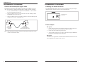
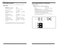
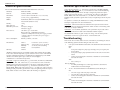
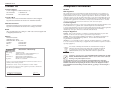
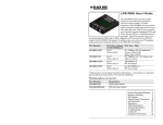
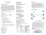
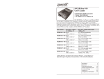
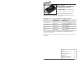
User’s Guide
M/GE-PSW-SX-01, M/GE-PSW-LX-01
Stand-Alone Media Converters
• Copper to Fiber
• 10/100/1000Base-T to 1000Base-X
The miniature plug-and-play M/GE-PSW-xX-01, 2port Ethernet/Fast Ethernet bridging media
converters allow integrating fiber optic cable to
10/100/1000 Unshielded Twisted Pair (UTP) environments while providing a spacesaving alternative to traditional sized media converters.
M/GE-PSW-xX-01:
Part Number
M/GE-PSW-SX-01
M/GE-PSW-LX-01
M/GE-PSW-LX-01
(100) **
M/GE-PSW-LX-01
(101)**
Auto-Negotiation, AutoCross, Link Pass-Through
Copper - Port
10/100/1000Base-T
RJ-45
100 m (328 ft)*
RJ-45
100 m (328 ft)*
RJ-45
100 m (328 ft)*
RJ-45
100 m (328 ft)*
Fiber-Optic -Port
1000Base-FX (SC)
SX, 850 nm, multimode 62.5/125
200m (722 ft), 50/125 550m (1,805 ft)
LX, 1310 nm single mode
10 km (2.1 miles)*
LX, 1310TX/1550RX nm, single mode
20 km (12.4 miles)*
LX, 1550TX/1310RX nm, single mode
20 km (12.4 miles)*
*Typical maximum cable distance; actual distance is dependent upon the physical
characteristics of the network.
**M/GE-PSW-LX-01(100) and M/GE-PSW-LX-01(101) are single-stand models and are
sold in pairs.
Installation . . . . . . . . . . . . . . . . . . . . .2
Operation . . . . . . . . . . . . . . . . . . . . .6
Cable Specifications . . . . . . . . . . . . .10
Technical Specifications . . . . . . . . . .12
Troubleshooting . . . . . . . . . . . . . . .13
Contact Us . . . . . . . . . . . . . . . . . . .14
Declaration of Conformity . . . . . . .14
Compliance Information . . . . . . . . .15
M/GE-PSW-xX-01
Installation
Installation—Continued
Copper and fiber ports
Connect the fiber cable
The illustration below shows the front panel of the M/GE-PSW-xX-01 media
converters.
Full duplex (always ON) is on the fiber side only; therefore, the 512-Bit Rule does not
apply. The cable lengths are constrained by the cable requirement.
1.
Locate or build IEEE 803.2™ compliant 1000Base-X fiber cable with male,
two-stranded TX to RX connectors installed at both ends.
2.
Connect the fiber cable to the M/GE-PSW-xX-01 media converters as follows:
•
•
3.
Connect the male TX cable connector to the female TX port.
Connect the male RX cable connector to the female RX port.
Connect the fiber cable to the other device (another media converter, hub, etc.)
as follows:
Connect the male TX cable connector to the female RX port.
Connect the male RX cable connector to the female TX port.
Front Panel
TP Link/Active
Fiber Link/Activity
TX
RX
Copper Port
Fiber Port
•
•
Power ON LED
Connect fiber cable
to media converter
as shown.
Electrostatic Discharge (ESD)
Always observe the following ESD precautions when installing or handing the
M/GE-PSW-xX-01 media converter:
2
•
Do not remove the converter from its protective packaging until you are ready to
install it.
•
Wear an ESD wrist grounding strap before handling any module or component. If
you do not have a wrist strap, maintain grounded contact with the system unit
throughout any procedure requiring ESD protection.
Tech Support: 1-800-260-1312 International: 00-1-952-941-7600 (24 hours)
RX
TX
Connect fiber cable
to other device
(media converter,
hub, etc.) as shown
RX
TX
Note: With AutoCross permanently enabled, the link LED only lights when a valid
end-to-end connection is made.
[email protected] -- Click the “Transition Now” link for a live Web chat.
3
M/GE-PSW-xX-01
Installation—Continued
Installation—Continued
Connect the twisted-pair copper cable
Powering the media converter
The AutoCross feature allows either MDI (straight-through) or MDI-X (crossover)
cable connections to be configured automatically, according to network conditions.
The M/GE-PSW-xX-01 media converter is powered by using a DC power adapter
through the barrel connector on its rear panel, as shown below.
1.
Locate or build IEEE 803.2™ compliant 10/100/1000Base-T cables with RJ45 connectors installed at both ends.
2.
Connect the RJ-45 connector at one end of the cable to the RJ-45 port on the
M/GE-PSW-xX-01 media converter.
3.
Connect the RJ-45 connector at the other end of the cable to the RJ-45 port on
the other device (switch, workstation, etc.).
Back Panel
Barrel Connector
5-28 VDC
M/GE-PSW-xX-01 Back Panel Power
Power adapter
RJ-45 port
on the media
converter
RJ-45 port
on the other device
(switch, work station, etc.)
Note: With AutoCross permanently enabled, the link LED only lights when a valid
end-to-end connection is made.
AC power
1.
Connect the barrel connector of the power adapter to the media converter’s
power port (located on the back panel of the media converter).
2.
Connect the power adapter plug to AC power.
3.
Verify that the media converter is powered up by observing the illuminated
LED power indicator light on the front panel.
DC power
Consult the user’s guide for the Transition Networks SPS-1872-SA DC external
power supply for powering the media converter.
4
Tech Support: 1-800-260-1312 International: 00-1-952-941-7600 (24 hours)
[email protected] -- Click the “Transition Now” link for a live Web chat.
5
M/GE-PSW-xX-01
Operation
Operation—Continued
Status LEDs
Product features
Use the LEDs to monitor the status of the media converter.
Front Panel
TP-Link/Act LED
Fiber-Link/Act LED
The Auto-Negotiation feature is ON permanently for the M/GE-PSW-xX-01 media
converters. Auto-Negotiation allows the media converter to configure itself
automatically to achieve the best possible mode of operation over a link. It
broadcasts speed (10 /100/1000 Mb/s) and duplex capabilities (full or half) to the
other device and negotiates the best mode of operation. Auto-Negotiation allows
quick and easy installation because the optimal link is established automatically.
LED states are as follows:
Fiber-Link/Act LED
ON
= Link (fiber)
Flashing = Activity
TP-Link/Act LED
Green
ON
= Link (copper)
Flashing = Activity
Power LED
Green
The M/GE-PSW-xX-01 media converters do not forward collision signals or error
packets from one collision domain to another, which results in improvements in
baseline network performance. In addition, the media converter filters packets
destined for local devices, which reduces network congestion.
Auto-Negotiation
Power ON LED
Green
Congestion reduction
In a scenario where an auto-negotiation device is linked to a non-negotiating device,
the negotiating device via parallel detection recognizes the speed of the second
device then establishes the best operating speed (10/100/100Mbs) at half-duplex.
AutoCross™
The AutoCross feature allows using either straight-through (MDI) or crossover
(MDI-X) copper cables when connecting to 10Base-T or 100Base-TX devices.
AutoCross determines the characteristics of the connection and automatically
configures the device to link up, regardless of the copper cable configuration, MDI
or MDI-X.
Link Pass-Through
ON
= Connected to power
The Link Pass-Through feature (illustrated below) allows the media converter to
monitor both the fiber and copper RX (receive) ports for loss of signal. In the event
of an RX signal loss (1), the media converter will automatically disable the TX
(transmit) signal (2), thus “passing through” the link loss (3). The far-end device is
automatically notified of the link loss (4), which prevents the loss of valuable data
unknowingly transmitted over an invalid link.
media converter A
disables the fiber TX link
Near-End
Device
1
Media
Converter A
original fault
on the copper link
2
media converter B
loses the fiber RX link
3
Media
Converter B
4
Far-End
Device
media converter B
disables the copper link
Note: Both copper and fiber cables must be installed before the LEDs will light.
6
Tech Support: 1-800-260-1312 International: 00-1-952-941-7600 (24 hours)
[email protected] -- Click the “Transition Now” link for a live Web chat.
7
M/GE-PSW-xX-01
Operation—Continued
Operation—Continued
Product features—continued
Product features—continued
Automatic link restoration
Distance extension
The media converter will automatically re-establish the link when connected to a
switch if the link is lost, even with Auto-Negotiation and Link Pass-through (both
directions) enabled.
The M/GE-PSW-xX-01 media converters can segment one (1) 10Base-T copper
Ethernet, 100Base-T copper fast Ethernet, or 1000Base-T copper Gigabit Ethernet,
and one (1)1000 Base-X fiber Fast Ethernet collision domain:
Full-duplex flow control
In a half-duplex Ethernet or Fast Ethernet environment, the M/GE-PSW-xX-01
media converters extend network distances by segmenting collision domains so that
the 512-Bit Rule applies separately to each collision domain.
In a full-duplex network, maximum cable lengths are determined by the type of
cables used—see front cover and cable specifications section.
The 512-Bit Rule does not apply in a full-duplex network.
Note: Full duplex is ON permanently for the fiber port only.
Half-duplex flow control (512-Bit Rule)
In a half-duplex network, the maximum cable lengths are determined by the roundtrip delay limitations of each Fast Ethernet collision domain. (A collision domain is
the longest path between any two terminal devices; e.g., a terminal, switch, or
router.)
The 512-Bit Rule determines the maximum length of cable permitted by calculating
the round-trip delay in bit-times (BT) of a particular collision domain. If the result
is less than or equal to 512 BT, the path is good.
In a full-duplex Ethernet or Fast Ethernet environment, the M/GE-PSW-xX-01
media converters extend network distances to the physical cable limitations
imposed by the selected twisted-pair copper fiber cables.
Rate conversion
The M/GE-PSW-xX-01 media converters allow the following connections:
•
10Mb/s devices on a 10Base-T legacy copper network to 1000Mb/s devices on
a 1000Base SX/LX Gigabit Ethernet fiber network.
•
100Mb/s devices on a 100Base-T legacy copper network to 1000Mb/s devices
on a 1000Base SX/LX Gigabit Ethernet fiber network.
For more information on the 512-Bit Rule, see the white paper titled “Collision
Domains” on the Transition Networks website at: www.transition.com
Back pressure
Back pressure is used in half duplex mode. It ensures the retransmission of
incoming packets when a port using half-duplex is temporarily unable to receive
incoming frames.
Flow control
The process of adjusting the flow of data from one device to another ensures that
the receiving device can handle all the incoming data. This is particularly important
where the sending device is capable of transmitting data much faster than the
receiving device can accept it.
8
Tech Support: 1-800-260-1312 International: 00-1-952-941-7600 (24 hours)
[email protected] -- Click the “Transition Now” link for a live Web chat.
9
M/GE-PSW-xX-01
Cable Specifications
Cable Specifications—Continued
The physical characteristics must meet or exceed IEEE 802.3™ specifications.
Fiber cable
Copper cable
Categories 5 and 5e: minimum requirement
Bit Error Rate:
single mode fiber (recommended):
Multimode fiber (recommended):
Multimode fiber (optional):
<10-9
9 µm
62.5/125 µm
100/140, 85/140, 50/125 µm
M/GE-PSW-SX-01
Fiber Optic Transmitter Power:
Fiber Optic Receiver Sensitivity:
Link Budget:
850nm multimode
min: -10.0 dBm
min: -17.0 dBm
7.0 dB
M/GE-PSW-LX-01
Fiber-optic Transmitter Power:
Fiber-optic Receiver Sensitivity:
Link Budget:
1310 nm single mode
min: -9.5 dBm
max: -3.0 dBm
min: -20.0 dBm
max: -3.0 dBm
10.5 dB
M/GE-PSW-LX-01(100)
M/GE-PSW-LX-01(101)
Fiber-optic Transmitter Power:
Fiber-optic Receiver Sensitivity:
Link Budget:
max: -4.0 dBm
max: -0.0 dBm
1310TX/1550RX nm single mode
1550TX/1310RX nm single mode
min: -8.0 dBm
max: -3.0 dBm
min: -21.0 dBm
max: -3.0 dBm
13 dB
Gauge
24 to 22 AWG
Attenuation
22.0 dB /100m @ 100 MHz
Maximum Cable Distance
100 meters
• Straight-through or crossover twisted-pair cable may be used.
• Shielded (STP) or unshielded (UTP) twisted-pair cable may be used.
• Pins 1&2 and 3&6 are the two active pairs in an Ethernet network.
• All four pairs are used in a gigabit Ethernet network.
• Use only dedicated wire pairs for the active pins:
(e.g., blue/white & white/blue, orange/white & white/orange, etc.)
• Do not use flat or silver satin wire.
S traig ht T hroug h C able
Twisted Pair #1
1
2
1
2
Twisted Pair #2
3
6
3
6
C ros s ove r C able
Twisted Pair #1
1
2
1
2
Twisted Pair #2
3
6
3
6
CAT5e Gigbit Ethernet
Straight-Through Cable
The fiber optic transmitters on this device meet Class I Laser safety requirements per
IEC-825/CDRH standards and comply with 21 CFR1040.10 and 21CFR1040.11.
10
Tech Support: 1-800-260-1312 International: 00-1-952-941-7600 (24 hours)
Twisted Pair #1
1
2
1
2
Twisted Pair #2
3
4
3
4
Twisted Pair #3
5
6
5
6
Twisted Pair #4
7
8
7
8
[email protected] -- Click the “Transition Now” link for a live Web chat.
11
M/GE-PSW-xX-01
Technical Specifications
Technical Specifications—Continued
For use with Transition Networks Model M/GE-PSW-xX-01 converters.
Standards:
IEEE 802.3-2000
Data rate:
10 Mb/s, 100 Mb/s, 1000 Mb/s
Dimensions:
1.8"W x 3.35"D x 0.85"H (45.7 x 85.1 x 21.6 mm)
Weight:
3.15 oz. (127.5 g) approximately
MTBF*:
24,466 hours (MIL217F2 V5.0) (MIL-HDBD-217F)
100,130 hours (Bellcore7 V5.0)
Memory:
MAC addresses:
Maximum packet size:
1Meg
8K
1632 bytes, untagged
1628 bytes, tagged
Power sources:
Unit will accept - 5 to 28 VDC
Barrel connector – Wall Mount AC Adapter
(400mA at 12VDC)(The external power supply provided
with this product is UL listed by the power supply’s
manufacturer.)
Power consumption:
262mA @ 12VDC, 3.15 watts
Environment:
Tmra**:
Storage Temp:
Humidity:
Altitude:
Warranty:
0°C to 50°C (32°F to 122°F )
-25°C to 65°C (-13°F to 149°F)
5% to 95%, non-condensing
0 to 10,000 feet
Copper-based media ports, e.g., Twisted Pair (TP) Ethernet, USB, RS232, RS422,
RS485, DS1, DS3, Video Coax, etc., are intended to be connected to intra-building
(inside plant) link segments that are not subject to lightening transients or power
faults. Copper based media ports, e.g., Twisted Pair (TP) Ethernet, USB, RS232,
RS422, RS485, DS1, DS3, Video Coax, etc., are NOT to be connected to interbuilding (outside plant) link segments that are subject to lightening transients or power
faults.
The product is certified by the manufacturer to comply with DHHS Rule 21/CFR,
Subchapter J applicable at the date of manufacture.
WARNING: Visible and invisible laser radiation when open. Do not stare into the
beam or view directly with optical instruments. Failure to observe this warning could
result in an eye injury or blindness.
WARNING: Use of controls, adjustments, or the performance of procedures other
than those specified herein could result in hazardous radiation exposure.
The information in this user’s guide is subject to change. For the most up-to-date
information, view the user’s guide on-line at: www.transition.com.
Troubleshooting
If the media converter fails, isolate and correct the failure by determining the answers
to the following questions and then taking the indicated action:
1.
Lifetime
*MTBF is estimated using the predictability method. This method is based on MIL217F at 25°C ambient temperature, typical enclosure heat rise of 10°C with nominal
operating conditions and parameters. Installation and configuration specific MTBF
estimates are available upon request. Contact Technical Support.
**Manufacturer’s rated ambient temperature.
CAUTION: Copper based media ports, e.g., Twisted Pair (TP) Ethernet, USB, RS232,
RS422, RS485, DS1, DS3, Video Coax, etc., are intended to be connected to intrabuilding (inside plant) link segments that are not subject to lightening transients or
power faults. Copper-based media ports, e.g., Twisted Pair (TP) Ethernet, USB,
RS232, RS422, RS485, DS1, DS3, Video Coax, etc., are NOT to be connected to interbuilding (outside plant) link segments that are subject to lightening transients or power
faults. Failure to observe this caution could result in damage to equipment.
12
Tech Support: 1-800-260-1312 International: 00-1-952-941-7600 (24 hours)
Is the power LED illuminated and did the TX and FX LEDs turn ON then turn
OFF?
NO
Is the power adapter the proper type of voltage and cycle frequency for
the AC outlet?
•
Is the power adapter properly installed in the media converter and in the
outlet?
•
Contact Technical Support: US/Canada: 1-800-260-1312, International:
00-1-952-941-7600.
YES
•
Proceed to step 2.
Note the following:
•
As a link pass-through device both copper and fiber cables must be
installed before the LEDs will light.
2.
Are the “TX and FX-Link/ACT” LEDs illuminated on the RJ-45 port ?
NO
•
Check the copper cables for proper connection.
•
Check the fiber cables for proper connection.
•
Contact Technical Support: US/Canada: 1-800-260-1312, International:
00-1-952-941-7600.
YES
•
Contact Technical Support: US/Canada: 1-800-260-1312, International:
00-1-952-941-7600.
[email protected] -- Click the “Transition Now” link for a live Web chat.
13
M/GE-PSW-xX-01
Contact Us
Compliance Information
Technical Support
Technical support is available 24 hours a day.
US and Canada:
1-800-260-1312
International:
00-1-952-941-7600
CE Mark
FCC Regulations
Transition Now
Chat live via the Web with Transition Networks Technical Support.
Log onto www.transition.com and click the Transition Now link.
Web-Based Seminars
Transition Networks provides seminars via live web-based training.
Log onto www.transition.com and click the Learning Center link.
E-Mail
Ask a question anytime by sending an e-mail to our technical support staff.
[email protected]
Address
Transition Networks
10900 Red Circle Drive
Minnetonka MN 55343, U.S.A.
telephone:
952-941-7600
toll free:
800-526-9267
fax:
952-941-2322
Declaration of Conformity
Name of Mfg:
Model:
Part Number(s):
Regulation:
Transition Networks
10900 Red Circle Drive, MinnetonkaMN 55343 U.S.A.
M/GE-PSW-xX-01 Series Media Converters
M/GE-PSW-LX-01, M/GE-PSW-SX-01,
M/GE-PSW-LX-01(100), M/GE-PSW-LX-01(101)
EMC Directive 89/336/EEC
Purpose: To declare that the M/GE-PSW-xX-01 to which this declaration refers is in
conformity with the following standards.
EN 55022:1994 + A1:1995 + A2:1997; EN 55024:1998 + A1:2001 + A2:2003
I, the undersigned, hereby declare that the equipment specified above conforms to the
above Directive(s) and Standard(s).
This equipment has been tested and found to comply with the limits for a class A digital device,
pursuant to part 15 of the FCC rules. These limits are designed to provide reasonable protection
against harmful interference when the equipment is operated in a commercial environment. This
equipment generates, uses, and can radiate radio frequency energy and, if not installed and used in
accordance with the instruction manual, may cause harmful interference to radio communications.
Operation of this equipment in a residential area is likely to cause harmful interference, in which
case the user will be required to correct the interference at the user's own expense.
Canadian Regulations
This digital apparatus does not exceed the Class A limits for radio noise for digital apparatus set out
on the radio interference regulations of the Canadian Department of Communications.
Le présent appareil numérique n'émet pas de bruits radioélectriques dépassant les limites applicables
aux appareils numériques de la Class A prescrites dans le Règlement sur le brouillage
radioélectrique édicté par le ministère des Communications du Canada.
European Regulations
Warning This is a Class A product. In a domestic environment this product may cause radio
interference in which case the user may be required to take adequate measures.
Achtung! Dieses ist ein Gerät der Funkstörgrenzwertklasse A. In Wohnbereichen können bei
Betrieb dieses Gerätes Rundfunkstörungen auftreten. In diesem Fäll ist der Benutzer für
Gegenmaßnahmen verantwortlich.
Attention! Ceci est un produit de Classe A. Dans un environment domestique, ce produit risque
de créer des interférences radioélectriques, il appartiendra alors à l'utilsateur de prende les measures
spécifiques appropriées.
In accordance with European Union Directive 2002/96/EC of the European
Parliament and of the Council of 27 January 2003, Transition Networks will
accept post usage returns of this product for proper disposal. The contact
information for this activity can be found in the 'Contact Us' portion of this
document.
CAUTION: RJ connectors are NOT INTENDED FOR CONNECTION TO THE
PUBLIC TELEPHONE NETWORK. Failure to observe this caution could result
in damage to the public telephone network.
Der Anschluss dieses Gerätes an ein öffentlickes Telekommunikationsnetz in den EGMitgliedstaaten verstösst gegen die jeweligen einzelstaatlichen Gesetze zur Anwendung der
Richtlinie 91/263/EWG zur Angleichung der Rechtsvorschriften der Mitgliedstaaten über
Telekommunikationsendeinrichtungen einschliesslich der gegenseitigen Anerkennung ihrer
Konformität.
February, 2009_____
Stephen Anderson, Vice President of Engineering
14
Date
Tech Support: 1-800-260-1312 International: 00-1-952-941-7600 (24 hours)
[email protected] -- Click the “Transition Now” link for a live Web chat.
15
M/GE-PSW-xX-01
Trademark Notice
All trademarks and registered trademarks are the property of their respective owners.
Copyright Restrictions
© 2001-2005 Transition Networks.
All rights reserved. No part of this work may be reproduced or used in any form or by any
means—graphic, electronic, or mechanical—without written permission from Transition
Networks.
16
Printed in the U.S.A.
33398.B