1
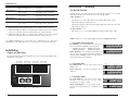
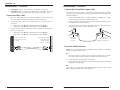
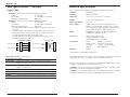
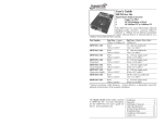
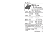
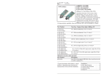
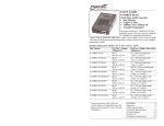
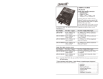
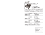
User’s Guide
SBFTF10xx-12x
Stand-Alone Media Converter
• Copper to Fiber
• 10/100 Bridging 6-Port
• (5 copper / 1 fiber)
• 10/100Base-TX to 100Base-FX
The SBFTF10xx-12x 6-port Ethernet/fast Ethernet bridging media converter allows
connection of 10Base-T Ethernet and/or 100Base-TX fast Ethernet twisted-pair
copper network devices to network devices on a 100Base-FX fast Ethernet fiber
network.
Part Number
Copper - five (5) ports Duplex Fiber-Optic - one (1) port
10Base-T/100Base-TX 100Base-FX
SBFTF1011-120
SBFTF1015-120
(long haul)
RJ-45
100 m (328 ft)*
RJ-45
100 m (328 ft)*
RJ-45
100 m (328 ft)*
RJ-45
100 m (328 ft)*
ST, 1300 nm multimode
2 km (1.2 miles)*
SC, 1300 nm multimode
2 km (1.2 miles)*
SC, 1310 nm single mode
20 km (12.4 miles)*
SC, 1310 nm single mode
40 km (24.8 miles)*
SBFTF1016-120
(extra long haul)
SBFTF1017-120
(long wave length)
RJ-45
100 m (328 ft)*
RJ-45
100 m (328 ft)*
SC, 1310 nm single mode
60 km (37.2 miles)*
SC, 1550 nm single mode
80 km (49.7 miles)*
SBFTF1018-120
RJ-45
100 m (328 ft)*
RJ-45
100 m (328 ft)*
MT-RJ, 1300 nm multimode
2 km (1.2 miles)*
MT-RJ, 1310 nm single mode
5 km (3.1 miles)*
SBFTF1013-120
SBFTF1014-120
SBFTF1025-120
* Typical maximum cable distance.
Actual distance is dependent upon the
physical characteristics of the network.
Installation . . . . . . . . . . . . . . . . . .2
Operation . . . . . . . . . . . . . . . . . . .8
Cable Specifications . . . . . . . . . .11
Technical Specifications . . . . . . .13
Troubleshooting . . . . . . . . . . . . .14
Compliance Information . . . . . . .15
Contact Us . . . . . . . . . . . . . . . . .16
SBFTF10xx-12x
Part Number
Copper - five (5) ports
Fiber-Optic - one (1) port
10Base-T/100Base-TX
Single Fiber
SBFTF1029-120 RJ-45
SC, 1310 nm (TX)/1550 nm (RX)
100 m (328 ft)*
single mode, 20 km (12.4 miles
SBFTF1029-121 RJ-45
SC, 1550 nm (TX)/1310 nm (RX)
100 m (328 ft)*
single mode, 20 km (12.4 miles)*
SBFTF1029-122 RJ-45
SC, 1310 nm (TX)/1550 nm (RX)
100 m (328 ft)*
single mode, 40 km (24.8 miles)*
SBFTF1029-123 RJ-45
SC, 1550 nm (TX)/1310 nm (RX)
100 m (328 ft)*
single mode, 40 km (24.8 miles)*
*
Typical maximum cable distance. Actual distance is dependent upon the
physical characteristics of the network. (TX) = transmit (RX) = receive
**
SBFTF1029-120 and -121 are intended to be installed in the same network
where one is the local converter and the other is the remote converter.
Installation -- Continued
Set the Dip Switches
The dip switches are located on the side of the media converter. Use a small,
flat-blade screwdriver or a similar device to set each dip switch.
“SW1” switches 1 - 6
Dip switches 1, 2, and 3 apply only to twisted-pair copper port 1 (TP1).
Dip switch 4 applies to fiber port 1 (F1).
Dip switch 5 applies to all twisted-pair copper ports (TP1, TP2, TP3, TP4, TP5).
Dip switch 6 is not in use.
“Config. Switches” 1 - 4
Dip switches 1, 2, 3, and 4 apply only to twisted-pair copper port 2 (TP2).
*** SBFTF1029-122 and -123 are intended to be installed in the same network
where one is the local converter and the other is the remote converter.
NOTE: Switches 1, 2, and 3 apply only to twisted-pair copper port 1 (TP1).
The chassis version of the media converter is CBFTF10xx-12x. For more
information, see the CBFTF10xx-12x user’s guide on-line at: www.transition.com.
1. Twisted-Pair Auto-Negotiation
Installation
Up (Enabled) - The media converter “advertises”
UP
ALL rate and mode capabilities to the network:
Twisted-Pair Auto-Negotiation ON
• 100Mb/s full-duplex • 100Mb/s half-duplex,
• 10Mb/s full-duplex • 10Mb/s half-duplex.
1
DOWN
Copper and Fiber Ports
The figure below illustrates the locations of the five (5) twisted-pair copper ports
and the one (1) fiber port.
Twisted-Pair
Port 2 (TP2)
Twisted-Pair
Port 3 (TP3)
Twisted-Pair
Port 4 (TP4)
Twisted-Pair
Port 5 (TP5)
Down (Disabled) - The bridging media converter
does not “advertise” the rate and mode capabilities Twisted-Pair Auto-Negotiation OFF
to the network. Switches 2 and 3 are then used to
set the twisted-pair rate and mode.
2. Twisted-Pair Rate
Up (100Base-TX) - Sets the twisted-pair rate to
100Base-TX.
2
UP
Down (10Base-T) - Sets the twisted-pair rate to Twisted-pair 100Base-TX
10Base-T.
DOWN
10/100TX
10/100TX
10/100TX
10/100TX
3. Twisted-Pair Mode
PWR
LACT
FD
100Base-FX
Fiber Port 1
(F1)
2
Twisted-pair 10Base-T
10/100TX
Twisted-Pair
Port 1 (TP1)
24-hour Technical Support: 1-800-260-1312 -- International: 00-1-952-941-7600
3
Up (Full-Duplex) - The twisted-pair cable
UP
distances are constrained by the cable
requirements (see pages 1 and 2).
Twisted-pair Full-Duplex
Down (Half-Duplex): - The twisted-pair cable
DOWN
distances are constrained by the 512-Bit Rule (see
Twisted-pair Half-Duplex
page 9).
[email protected] -- Click the “Transition Now” link for a live Web chat.
3
SBFTF10xx-12x
Installation -- Continued
Installation -- Continued
Set the Dip Switches -- Continued
Set the Dip Switches -- Continued
NOTE: Dip switch 4 (in the “SW” set) applies to fiber port 1 (F1).
NOTE: Dip switches 1, 2, 3, and 4 (in the Config. Switches set) apply ONLY to
twisted-pair copper port 2 (TP2).
4. Fiber Mode (Fiber Port 1)
4
Up (Full-Duplex) - The cable distances for fiber port
UP
1 (F1) are constrained by the cable requirements (see
pages 1 and 2).
Fiber Full-Duplex
Down (Half-Duplex) - The cable distances for fiber
DOWN
port 1 (F1) are constrained by the 512-Bit Rule (see
Fiber Half-Duplex
page 9).
NOTE: DIP switch 5 (in the “SW” set) applies to ALL twisted-pair copper ports
(TP1, TP2, TP3, TP4, TP5).
5. AutoCross
1. Twisted-Pair Auto-Negotiation
1
Up (Enabled) - The media converter “advertises”
UP
ALL rate and mode capabilities to the network:
• 100Mb/s full-duplex • 100Mb/s half-duplex, Twisted-Pair Auto-Negotiation ON
• 10Mb/s full-duplex • 10Mb/s half-duplex.
DOWN
Down (Disabled) - The bridging media converter
does not “advertise” the rate and mode Twisted-Pair Auto-Negotiation OFF
capabilities to the network. Switch 2 and switch 3
are then used to set the twisted-pair rate and mode.
5
Up (Enable) - The media converter connects
UP
automatically to either straight-through or crossover
AutoCross Enable
twisted-pair copper cable.
Down (Disable) - Either straight-through or crossover
DOWN
twisted-pair copper cable must be installed,
AutoCross Disable
according to the site requirements
2
2. Twisted-Pair Rate
UP
Up (100Base-TX) - Sets the twisted-pair rate to
100Base-TX.
Twisted-Pair 100Base-TX
Down (10Base-T) - Sets the twisted-pair rate to
DOWN
10Base-T.
Twisted-Pair 10Base-T
6. Not in use
3. Twisted-Pair Mode
Up (Full-Duplex) - The twisted-pair cable
UP
distances are constrained by the cable
requirements (see pages 1 and 2).
Twisted-Pair Full-Duplex
Down (Half-Duplex) - The twisted-pair cable
DOWN
distances are constrained by the 512-Bit Rule (see
Twisted-Pair
Half-Duplex
page 9).
3
4. Monitor for Twisted-Pair Port 2 (TP2)
4
Up (Off) - The twisted-pair port 2 (TP2) functions
as directed by switches 1, 2, and 3.
UP
Down (On) - The twisted-pair port 2 (TP2) Monitor on TP2 OFF
functions as a “sniffer” port and transmits all
packets received from ports F1 and TP1.
DOWN
Monitor on TP2 ON
4
24-hour Technical Support: 1-800-260-1312 -- International: 00-1-952-941-7600
[email protected] -- Click the “Transition Now” link for a live Web chat.
5
SBFTF10xx-12x
Installation -- Continued
•
•
Installation -- Continued
If half-duplex mode is used, refer to the 512-Bit Rule (see page 9).
If full-duplex mode is used, the 512-Bit Rule does not apply. The cable
lengths are constrained by the cable requirements (see pages 1 and 2).
Connect the Fiber Cable
Connect the Twisted-Pair Copper Cable
The AutoCross feature allows either MDI (straight-through) or MDI-X
(crossover) cable connections to be configured automatically, according to the
network conditions.
1.
Locate or build IEEE 803.2™ compliant 100Base-FX fiber cable with
male, two-stranded TX to RX connectors installed at both ends.
1. Locate or build IEEE 803.2™ compliant 10Base-T or 100Base-TX cables,
with male, RJ-45 connectors installed at both ends.
2.
Connect the fiber cables to the SBFTF10xx-12x media converter as
described:
• Connect the male TX cable connector to the female TX port.
• Connect the male RX cable connector to the female RX port.
2.
Connect the RJ-45 connector at one end of the cable to the RJ-45 port on
the SBFTF10xx-12x media converter.
3.
Connect the RJ-45 connector at the other end of the cable to the RJ-45
port on the other device (switch, workstation, etc.).
3.
Connect the fiber cables to the other device (another media converter,
hub, etc.) as described:
• Connect the male TX cable connector to the female RX port.
• Connect the male RX cable connector to the female TX port.
Connect the fiber cable
to the media converter
as shown.
RJ-45 port
on the media
converter
Connect the fiber cable
to the other device
(media converter,
hub, etc.) as shown
RX
RX
TX
TX
RJ-45 port
on the other device
(switch, work station, etc.)
Power the Media Converter
NOTE: The external power supply provided with this product is UL listed by
the power supply’s manufacturer.
AC
1.
Connect the barrel connector on the power adapter to the media
converter’s power port (located on the back of the media converter).
2.
Connect the power adapter plug to AC power.
3.
Verify that the media converter is powered by observing the illuminated
LED power indicator light.
DC
Consult the user’s guide for the Transition Networks SPS1872-xx DC external
power supply for powering the media converter.
6
24-hour Technical Support: 1-800-260-1312 -- International: 00-1-952-941-7600
[email protected] -- Click the “Transition Now” link for a live Web chat.
7
SBFTF10xx-12x
Operation
Operation -- Continued
Status LEDs
Product Features
Use the status LEDs next to the fiber ports to monitor the media converter and
the fiber network connections.
PWR
The “FD” and “LACT” LEDs near the bottom of the media
converter refer to Fiber Port 1 (F1).
LACT
Full-Duplex Network
In a full-duplex network, maximum cable lengths are determined by the type
of cables that are used. See pages 1 and 2 for the cable specifications for the
different SBFTF10xx-12x models.
The 512-Bit Rule does not apply in a full-duplex network.
FD
10
F(ull) D(uplex)
Half-Duplex Network (512-Bit Rule)
On = Full-duplex connection.
In a half-duplex network, the maximum cable lengths are determined by the
round trip delay limitations of each fast Ethernet collision domain. (A
collision domain is the longest path between any two terminal devices, e.g. a
terminal, switch, or router.)
Off = Half-duplex connection.
L(ink) ACT(ivity)
On = Fiber link connection.
The 512-Bit Rule determines the maximum length of cable permitted by
calculating the round-trip delay in bit-times (BT) of a particular collision
domain. If the result is less than or equal to 512 BT, the path is good.
Flashing = Fiber network activity.
P(o)W(e)R
For more information on the 512-Bit Rule, see the white paper titled
“Collision Domains” on the Transition Networks website at:
www.transition.com.
On = Connection to external AC or DC power.
Use the bi-color twisted-pair status LEDs to monitor the twisted-pair copper
network connections.
Duplex/Link LED
Duplex/Link Speed
Amber = A link on the half-duplex twisted-pair
copper link.
Flashing Amber = Activity on the half-duplex
copper link.
The SBFTF10xx-12x 6-point bridging media converter segments up to five (5)
10Base-T copper Ethernet and/or 100Base-TX copper fast Ethernet and one
(1) 100Base-FX fiber fast Ethernet collision domains.
In a half-duplex Ethernet or fast Ethernet environment, the SBFTF10xx-12x
media converter extends network distances by segmenting collision domains
so that the 512-Bit Rule applies separately to each collision domain (see page
9).
Green = A link on the full-duplex twisted-pair
copper link.
Flashing Green = Activity on the full-duplex
copper link.
Distance Extension
10/100TX
Speed LED
In a full-duplex Ethernet or fast Ethernet environment, the SBFTF10xx-12x
media converter extends network distances to the physical cable limitations
imposed by the selected twisted-pair copper fiber cables (see pages 1 and 2).
Amber = 10Mb/s operation.
Green = 100Mb/s operation.
8
24-hour Technical Support: 1-800-260-1312 -- International: 00-1-952-941-7600
[email protected] -- Click the “Transition Now” link for a live Web chat.
9
SBFTF10xx-12x
Operation -- Continued
Product Features -- Continued
Cable Specifications
The physical characteristics must meet or exceed IEEE 802.3™ specifications.
Fiber Cable
Rate Conversion
The SBFTF10xx-12x media converter allows connection of 10Mb/s terminal
devices on a 10Base-T legacy Ethernet copper network to 100Mb/s terminal
devices on a 100Base-TX fast Ethernet copper network and/or to 100Mb/s
terminal devices on a 100Base-FX fast Ethernet fiber network.
Congestion Reduction
The SBFTF10xx-12x media converter does not forward collision signals or
error packets from one collision domain to another, improving baseline
network performance. In addition, the media converter filters packets
destined for local devices, also reducing network congestion.
Auto-Negotiation
The Auto-Negotiation feature allows the SBFTF10xx-12x media converter to
automatically configure itself to achieve the best possible mode of operation
over a link. The media converter broadcasts its speed (10 Mb/s or 100 Mb/s)
and duplex capabilities (full or half) to the other devices and negotiates the
best mode of operation. Auto-Negotiation allows quick and easy installation
because the optimal link is established automatically.
A scenario where the media converter is linked to a non-negotiating device is
a case where the user may want to disable Auto-Negotiation. In this instance,
the mode of operation will drop to the least common denominator between
the two devices (e.g.: 10 Mb/s, half-duplex). Disabling this feature gives the
user the ability to force the connection to the desired speed and duplex mode
of operation.
AutoCross™
When the AutoCross feature is activated, it allows either straight-through
(MDI) or crossover (MDI-X) copper cables to be used when connecting to
10Base-T or 100Base-TX devices. AutoCross determines the characteristics of
the connection and automatically configures the unit to link up, regardless if
the copper cable is MDI or MDI-X configuration. (Transition networks
recommends leaving the device in the default “enable” mode.)
Bit Error Rate:
single mode fiber (recommended):
Multimode fiber (recommended):
Multimode fiber (optional):
<10-9
9 µm
62.5/125 µm
100/140, 85/140, 50/125 µm
SBFTF1011-120
SBFTF1013-120
Fiber Optic Transmitter Power:
Fiber Optic Receiver Sensitivity:
Link Budget:
1300 nm multimode
1300 nm multimode
min: -19.0 dBm
max: -14.0 dBm
min: -30.0 dBm
max: -14.0 dBm
11.0 dB
SBFTF1014-120
Fiber-optic Transmitter Power:
Fiber-optic Receiver Sensitivity:
Link Budget:
1310 nm single mode
min: -15.0 dBm
max: -8.0 dBm
min: -31.0 dBm
max: -8.0 dBm
16.0 dB
SBFTF1015-120 (long haul)
Fiber-optic Transmitter Power:
Fiber-optic Receiver Sensitivity:
Link Budget:
1310 nm single mode
min: -8.0 dBm
max: -2.0 dBm
min: -34.0 dBm
max: -7.0 dBm
26.0 dB
SBFTF1016-120 (extra long haul)
Fiber-optic Transmitter Power:
Fiber-optic Receiver Sensitivity:
Link Budget:
1310 nm single mode
min: -5.0 dBm
max: 0.0 dBm
min: -34.0 dBm
max: -7.0 dBm
29.0 dB
SBFTF1017-120 (long wave length)
Fiber-optic Transmitter Power:
Fiber-optic Receiver Sensitivity:
Link Budget:
1550 nm single mode
min: -5.0 dBm
max: 0.0 dBm
min: -34.0 dBm
max: -7.0 dBm
29.0 dB
SBFTF1018-120
Fiber-optic Transmitter Power:
Fiber-optic Receiver Sensitivity:
Link Budget:
1300 nm multimode
min: -19.0 dBm
max: -14.0 dBm
min: -33.5 dBm
max: -14.0 dBm
14.5 dB
SBFTF1025-120
Fiber-optic Transmitter Power:
Fiber-optic Receiver Sensitivity:
Link Budget:
1310 nm single mode
min: -11.0 dBm
max: -3.0 dBm
min: -20.0 dBm
max: -3.0 dBm
9.0 dB
SBFTF1029-120
SBFTF1029-121
Fiber-optic Transmitter Power:
Fiber-optic Receiver Sensitivity:
Link Budget:
1310 nm (TX) / 1550 nm (RX) simplex
1550 nm (TX) / 1310 nm (RX) simplex
min: -13.0 dBm
max: -6.0 dBm
min: -32.0 dBm
max: -3.0 dBm
19.0 dB
SBFTF1029-122
SBFTF1029-123
Fiber-optic Transmitter Power:
Fiber-optic Receiver Sensitivity:
Link Budget:
1310 nm (TX) / 1550 nm (RX) simplex
1550 nm (TX) / 1310 nm (RX) simplex
min: -8.0 dBm
max: -3.0 dBm
min: -33.0 dBm
max: -3.0 dBm
25.0 dB
The fiber optic transmitters on this device meets Class I Laser safety
requirements per IEC-825/CDRH standards and complies with 21
CFR1040.10 and 21CFR1040.11.
10
24-hour Technical Support: 1-800-260-1312 -- International: 00-1-952-941-7600
[email protected] -- Click the “Transition Now” link for a live Web chat.
11
SBFTF10xx-12x
Cable Specifications -- Continued
Technical Specifications
Copper Cable
For use with Transition Networks Model SBFTF10xx-12x or equivalent.
Category 3: (Minimum requirement for 10 Mb/s operation)
Standards
IEEE 802.3™
Gauge
24 to 22 AWG
Attenuation
11.5 dB/100m @ 5-10 MHz
Maximum Cable Distance
100 meters
Category 5: (Minimum requirement for 100 Mb/s operation)
Gauge
24 to 22 AWG
Attenuation
22.0 dB /100m @ 100 MHz
Maximum Cable Distance
100 meters
• Straight-through (MDI) or crossover (MDI-X) twisted-pair cable may
be used.
• Shielded (STP) or unshielded (UTP) twisted-pair cable may be used.
• Pins 1&2 and 3&6 are the two active pairs in an Ethernet network .
• Use only dedicated wire pairs for the active pins:
(e.g., blue/white & white/blue, orange/white & white/orange, etc.)
• Do not use flat or silver satin wire.
Data Rate
10 Mb/s, 100 Mb/s
Dimensions
3.25" x 1.75" x 4.8" (82 x 43 x 122 mm)
Weight
13 oz. (369 g) (approximate)
Power Consumption
4.95 watts
Power Supply
12VDC, 0.8 A (N. America, Europe, Japan, UK)
12VDC, 1.25 A (Latin Am., Australia, N.Z., S. Africa)
The external power supply provided with this product
is UL listed by the power supply’s manufacturer.
MTBF
48,000 hours (MIL217F2 V5.0) (MIL-HDBD-217F)
129,000 hours (Bellcore7 V5.0)
Packet Size:
Unicast MAC addresses: 4K
Memory: 256K bytes (2 Mbit)
Maximum packet size: 1536 bytes
Environment
Tmra*:
Storage Temp:
Humidity:
Altitude:
Warranty
Lifetime
Straight-Through Cable
Twisted Pair #1
1
2
1
2
Twisted Pair #2
3
6
3
6
Crossover Cable
Twisted Pair #1
1
2
1
2
Twisted Pair #2
3
6
3
6
0 to 50°C (32 to 122°F )
-20 to 85°C (-4 to 185°F)
5 to 95%, non condensing
0 to 10,000 feet
*Manufacturer’s rated ambient temperature.
Optional Accessories (sold separately)
Part Number Description
SPS-1872-SA Optional External Power Supply; 18-72VDC Stand-Alone
Output: 12.6VDC, 1.0 A
SPS-1872-DPS Optional External Power Supply; 18-72VDC Piggy-back;
Output: 12.6VDC, 1.0 A
WMBL
Optional Wall Mount Brackets; Length: 4.7in. (119mm)
WMBV
Optional Vertical Mount Bracket; Length: 5.0in. (127mm)
WMBD
Optional DIN Rail Mount Bracket; Length: 5.0in. (127mm)
WMBD-F
Optional DIN Rail Mount Bracket (flat); Length: 3.3in. (84mm)
12
24-hour Technical Support: 1-800-260-1312 -- International: 00-1-952-941-7600
The information in this user’s guide is subject to change. For the most up-to-date
information, view the user’s guide on-line at: www.transition.com.
Product is certified by the manufacturer to comply with DHHS Rule 21/CFR,
Subchapter J applicable at the date of manufacture.
CAUTION: Visible and invisible laser radiation when open. Do not stare into
the beam or view directly with optical instruments.
CAUTION: Use of controls, adjustments or the performance of procedures other
than those specified herein may result in hazardous radiation exposure.
[email protected] -- Click the “Transition Now” link for a live Web chat.
13
SBFTF10xx-12x
Troubleshooting
Compliance Information
If the media converter fails, isolate and correct the failure by determining the
answers to the following questions and then taking the indicated action:
CISPR22/EN55022 Class A + EN55024
CE Mark
1.
FCC Regulations
2.
3.
4.
14
Is the power LED on the media converter illuminated?
NO
• Is the power adapter the proper type of voltage and cycle frequency
for the AC outlet? (See “Power Supply” on page 13.)
• Is the power adapter properly installed in the media converter and in
the outlet?
• Contact Technical Support: US/Canada: 1-800-260-1312,
International: 00-1-952-941-7600.
YES
• Proceed to step 2.
Is the “Duplex/Link” LED illuminated on a port with twisted-pair cable
installed?
NO
• Check the copper cables for proper connection.
• Contact Technical Support: US/Canada: 1-800-260-1312,
International: 00-1-952-941-7600.
YES
• Amber = The media converter has selected half-duplex mode.
• Green = The media converter has selected full-duplex mode.
• If the mode is not correct, disconnect and reconnect the twisted pair
cable to restart the initialization process.
• Proceed to step 3.
Is the “LACT” LED illuminated on the fiber cable port?
NO
• Check the fiber cables for proper connection.
• Verify that the TX and RX cables are connected to the RX and TX
ports, respectively, on the 100Base-FX device.
• Contact Technical Support: US/Canada: 1-800-260-1312,
International: 00-1-952-941-7600.
YES
• Proceed to step 4.
Is the “Speed” LED illuminated on a port with twisted-pair cable
installed?
NO
• Check the copper cables for proper connection.
• Contact Technical Support: US/Canada: 1-800-260-1312,
International: 00-1-952-941-7600.
YES
• Amber = The media converter has selected 10Mb/s operation.
• Green = The media converter has selected 100Mb/s operation.
• If the speed is not correct, disconnect and reconnect the twisted pair
cable to restart the initialization process.
• Contact Technical Support: US/Canada: 1-800-260-1312,
International: 00-1-952-941-7600.
24-hour Technical Support: 1-800-260-1312 -- International: 00-1-952-941-7600
This equipment has been tested and found to comply with the limits for a Class A digital
device, pursuant to part 15 of the FCC rules. These limits are designed to provide reasonable
protection against harmful interference when the equipment is operated in a commercial
environment. This equipment generates, uses, and can radiate radio frequency energy and, if
not installed and used in accordance with the instruction manual, may cause harmful
interference to radio communications. Operation of this equipment in a residential area is
likely to cause harmful interference, in which case the user will be required to correct the
interference at the user's own expense.
Canadian Regulations
This digital apparatus does not exceed the Class A limits for radio noise for digital apparatus
set out on the radio interference regulations of the Canadian Department of Communications.
Le présent appareil numérique n'émet pas de bruits radioélectriques dépassant les limites
applicables aux appareils numériques de la Class A prescrites dans le Règlement sur le
brouillage radioélectrique édicté par le ministère des Communications du Canada.
European Regulations
Warning This is a Class A product. In a domestic environment this product may cause radio
interference in which case the user may be required to take adequate measures.
Achtung! Dieses ist ein Gerät der Funkstörgrenzwertklasse A. In Wohnbereichen können
bei Betrieb dieses Gerätes Rundfunkstörungen auftreten. In diesem Fäll ist der Benutzer für
Gegenmaßnahmen verantwortlich.
Attention! Ceci est un produit de Classe A. Dans un environment domestique, ce produit
risque de créer des interférences radioélectriques, il appartiendra alors à l'utilsateur de
prende les measures spécifiques appropriées.
VCCI Class 1 Compliance
This equipment is in the 1st Class category (information equipment to be used in commercial
and/or industrial areas) and conforms to the standards set by the Voluntary Control Council
For Interference by Data Processing
Equipment and Electronic Office
Machines aimed at preventing radio
interference in commercial and/or
industrial areas. When used in a
residential area or in an adjacent area
thereto, interference may be caused to
radio and TV receivers, etc. Read the
instructions for correct handling.
CAUTION: RJ connectors are NOT INTENDED FOR CONNECTION TO THE
PUBLIC TELEPHONE NETWORK. Failure to observe this caution could result in
damage to the public telephone network.
Der Anschluss dieses Gerätes an ein öffentlickes Telekommunikationsnetz in den EGMitgliedstaaten verstösst gegen die jeweligen einzelstaatlichen Gesetze zur Anwendung der
Richtlinie 91/263/EWG zur Angleichung der Rechtsvorschriften der Mitgliedstaaten über
Telekommunikationsendeinrichtungen einschliesslich der gegenseitigen Anerkennung ihrer
Konformität.
[email protected] -- Click the “Transition Now” link for a live Web chat.
15
Contact Us
Technical Support
Technical support is available 24 hours a day.
US and Canada:
1-800-260-1312
International:
00-1-952-941-7600
Transition Now
Chat live via the Web with Transition Networks Technical Support.
Log onto www.transition.com and click the Transition Now link.
Web-Based Seminars
Transition Networks provides seminars via live web-based training.
Log onto www.transition.com and click the Learning Center link.
E-Mail
Ask a question anytime by sending an e-mail to our technical support staff.
[email protected]
Address
Transition Networks
6475 City West Parkway
Minneapolis, MN 55344, USA
telephone:
952-941-7600
toll free:
800-526-9267
fax:
952-941-2322
Declaration of Conformity
Name of Mfg:
Transition Networks
6475 City West Parkway, Minneapolis MN 55344 USA
Model:
SBFTF10xx-12x Series Media Converters
Part Number(s):
SBFTF1011-120, SBFTF1013-120, SBFTF1014-120, SBFTF1015-120,
SBFTF1016-120, SBFTF1017-120, SBFTF1018-120, SBFTF1025-120,
SBFTF1029-120, SBFTF1029-121, SBFTF1029-122, SBFTF1029-123
Regulation:
EMC Directive 89/336/EEC
Purpose: To declare that the SBFTF10xx-12x to which this declaration refers is
in conformity with the following standards.
CISPR 22:1993; EN 55022:1994; EN 55024:1998; FCC Part 15 Subpart B;
21 CFR subpart J; EN 61000-3-2:1995; EN61000-3-3:1995
I, the undersigned, hereby declare that the equipment specified above conforms to the above
Directive(s) and Standard(s).
_April 16, 2001_____
Stephen Anderson, Vice-President of Engineering
Date
Trademark Notice
All trademarks and registered trademarks are the property of their respective owners.
Copyright Restrictions
© 2001-2005 Transition Networks.
All rights reserved. No part of this work may be reproduced or used in any form or by any
means - graphic, electronic, or mechanical - without written permission from Transition
Networks.
Printed in the U.S.A.
33223.E