1
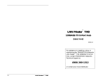
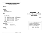
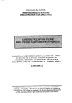
STACKMASTER TX12 SPECIFICATIONS
Standards
IEEE 802.3u 100BASE-TX
Class 1 (stacked)
Class 2 (unstacked)
Physical
Dimensions
17’ x 10’ x .1.8’
(438 mm x 255 mm x 45 mm)
Shipping Weight
9 lbs
™
StackMaster TX12
(4.1 kg)
Input Power
Internal universal input; 100–240VAC, 50/60 Hz, 53W
AC Input Cord:
TN PN
Requirement
3344
120 volts, 60 hertz
3344
100 volts, 50-60 hertz
3347
230 volts, 50 hertz
3348
240 volts, 50 hertz
3349
240 volts, 50 hertz
(SMHB-E-TX-12)
Location
USA/Canada/Mexico
Japan
Europe
Australia
United Kingdom
MTBF
50,000 hours
Environment
Temperature:
Humidity
Altitude
Warranty
Lifetime
17
100BASE-TX 12-Port Stackable Hub
0-50°C (32° to 122° F )
10-90%, non condensing
0-10,000 feet
33010.B
For assistance in installing, using, or
maintaining the TRANSITION Networks
StackMaster™ TX12 100BASE-TX 12-Port
Stackable Hub, contact TRANSITION
Networks Technical Support at:
(800) 260-1312
or contact your local distributor.
CAUTION: RJ connectors are NOT INTENDED FOR
CONNECTION TO THE PUBLIC TELEPHONE
NETWORK. Failure to observe this caution could result
in damage to the public telephone network.
100BASE-TX Cable and Connector Specifications
Der Anschluss dieses Gerätes an ein öffentlickes
Telekommunikationsnetz in den EG-Mitgliedstaaten verstösst gegen die
jeweligen einzelstaatlichen Gesetze zur Anwendung der Richtlinie
91/263/EWG zur Angleichung der Rechtsvorschriften der
Mitgliedstaaten über Telekommunikationsendeinrichtungen
einschliesslich der gegenseitigen Anerkennung ihrer Konformität.
100BASE-TX CABLE SPECIFICATIONS
Category 5 wire or better is required. Either shielded twisted pair
(STP) or unshielded twisted pair (UTP) can be used. DO NOT USE
FLAT OR SILVER SATIN WIRE.
The physical characteristics of the 100BASE-TX cable must meet or
exceed IEEE 802.3u 100BASE-TX specifications.
Category 5:
Gauge
Attenuation
Impedance
Compliance Information
UL Listed
C-UL Listed (Canada)
CISPR/EN55022 Class A
Maximum Cable Distance:
24 to 22 AWG
20 dB/1000’ @ 10 MHz
100 Ω ±10% @ 10 MHz
100 meters (330 feet)
FCC Regulations
This equipment has been tested and found to comply with the limits for a class
A digital device, pursuant to part 15 of the FCC rules. These limits are
designed to provide reasonable protection against harmful interference when
the equipment is operated in a commercial environment. This equipment
generates, uses, and can radiate radio frequency energy and, if not installed
and used in accordance with the instruction manual, may cause harmful
interference to radio communications. Operation of this equipment in a
residential area is likely to cause harmful interference, in which case the user
will be required to correct the interference at the user’s own expense.
Canadian Regulations
This digital apparatus does not exceed the Class A limits for radio noise for
digital apparatus set out on the radio interference regulations of the Canadian
Department of Communications.
100BASE-TX CONNECTOR CHARACTERISTICS:
The 100BASE-TX connectors are standard RJ-45 connectors with
standard pinning.
The two active pairs in a 100BASE-TX network are pins 1 & 2 and
pins 3 & 6. Use only dedicated wire pairs (such as blue/white &
white/blue, orange/white & white/orange) for the active pins.
100BASE-TX cable for unlike devices (such as hub to terminal
device) must be configured as straight through; 100BASE-TX cable
for like devices (such as hub to hub or terminal device to terminal
device) must be configured as crossover.
Straight Through Cable
Crossover Cable
European Regulations
Warning
Twisted
Pair #1
Twisted
Pair #1
This is a Class A product. In a domestic environment this product may cause
radio interference in which case the user may be required to take adequate
measures.
Twisted
Pair #2
Twisted
Pair #2
Copyright Restrictions
Connectors for unlike devices
© 1996, 1997 TRANSITION Networks.
All rights reserved. No part of this work may be reproduced or used in any
form or by any means – graphic, electronic, or mechanical – without written
permission from TRANSITION Networks.
Trademark Notice
Connectors for like devices
NOTE: MDI/MDI-X connectors on hubs allow straight-through
cable to be used in a crossover configuration for hub to hub
connection.
All registered trademarks and trademarks are the property of their respective
owners.
StackMaster™ TX12
100BASE-TX 12-Port Stackable Hub
16
FAST ETHERNET (IOOBASE-X)
CABLE SPECIFICATIONS
Due to the limited collision domain in 100BASE-X, use the shortest
cables possible to make a connection between any two devices.
Where collisions are not a consideration (full duplex), longer
cable may be possible.
Effective cable distances are determined by ambient RF noise and
by signal loss in the cable. Since fiber has low signal loss/meter
and invulnerability to RF noise, fiber is the preferred medium for
extending distances.
100BASE-FX Cable and Connector Specifications
The physical characteristics of the 100BASE-FX cable must meet or
exceed IEEE 802.3 100BASE-FX specifications.
100BASE-FX CABLE SPECIFICATIONS
Fiber Optic Cable Recommended:
Optional:
Fiber Optic Transmitter Power:
Average power:
Fiber Optic Receiver Sensitivity:
Average sensitivity:
Bit error rate:
Maximum Cable Distance:
62.5 / 125 µm multimode fiber
100 / 140 µm multimode fiber
85 / 125 µm multimode fiber
50 / 125 µm multimode fiber
-19.0 dBm
-33.5 dBm
≤10-10
2000 meters (6500 feet)
Table of Contents
1 INTRODUCTION . . . . . . . . . . . . . . . . . . . . . . . . . 1
The StackMaster TX12 Hub . . . . . . . . . . . . . . . . . . . . . . . . . .1
StackMaster TX12 Hub Features . . . . . . . . . . . . . . . . . . . . . . . .1
Networking the StackMaster TX12 Hub . . . . . . . . . . . . . . . . . . .2
StackMaster TX12 Hub Connectors and Status LEDs . . . . . . .3
RJ-45 Connectors . . . . . . . . . . . . . . . . . . . . . . . . . . . . . . . . . . .3
SCSI Connectors . . . . . . . . . . . . . . . . . . . . . . . . . . . . . . . . . . . .3
Power Connector . . . . . . . . . . . . . . . . . . . . . . . . . . . . . . . . . . .3
Status LEDs . . . . . . . . . . . . . . . . . . . . . . . . . . . . . . . . . . . . . . . .3
2 SITE CONSIDERATIONS. . . . . . . . . . . . . . . . . . . . 4
3 INSTALLATION. . . . . . . . . . . . . . . . . . . . . . . . . . . 5
Unpacking 12-Port Stackable Hub . . . . . . . . . . . . . . . . . . . . .5
Installing StackMaster™ TX12 in 19-inch Rack . . . . . . . . . . .6
Optionally Cascading 12-Port Stackable Hubs . . . . . . . . . . . .7
Using Port 12 to Cascade Two Hubs . . . . . . . . . . . . . . . . . . . . .7
Using SCSI Connectors to Cascade Stacked Hubs . . . . . . . . . . .8
Connecting 100BASE-TX Cable . . . . . . . . . . . . . . . . . . . . . . .9
Connecting Power to StackMaster™ TX12 . . . . . . . . . . . . . .10
4 OPERATION . . . . . . . . . . . . . . . . . . . . . . . . . . . . 11
5 MAINTENANCE . . . . . . . . . . . . . . . . . . . . . . . . . 12
Fault Isolation . . . . . . . . . . . . . . . . . . . . . . . . . . . . . . . . . . .12
Technical Support Contact . . . . . . . . . . . . . . . . . . . . . . . . .12
100BASE-FX CONNECTOR CHARACTERISTICS:
The 100BASE-FX connectors are standard ST connectors.
WARRANTY STATEMENT . . . . . . . . . . . . . . . . . . . . . . . . . . . 13
SC connectors are available.
CABLE SPECIFICATIONS . . . . . . . . . . . . . . . . . . . . . . . . . . . . 15
STACKMASTER TX12 HUB SPECIFICATIONS. . . . . . . . . . . 17
15
StackMaster™ TX12
100BASE-TX 12-Port Stackable Hub
i
1. INTRODUCTION
This guide is intended for the system or network administrator
responsible for installing and monitoring a TRANSITION Networks
StackMasterTX-12 100BASE-TX 12-Port Stackable Hub. A working
knowledge of local area network (LAN) operations, including
familiarity with communications protocols used on interconnected
LANs, is assumed.
The StackMaster TX12 Hub
The StackMasterTX-12 100BASE-TX 12-Port Stackable Hub (SMHBE-TX-12) is a Fast Ethernet repeater designed to meet IEEE 802.3u
100BASE-TX standards.
StackMaster TX12 Hub Features
1
•
Twelve RJ-45 100BASE-TX ports for Fast Ethernet
connectivity
•
Port #12 provides StackMaster TX12-to-StackMaster TX12
MDI/MDI-X uplink option
•
Optional cascading of hubs using SCSI connectors at back
•
19-inch rack mountable
•
Auto partitioning of ports with excessive collisions
•
Fully automatic preamble regeneration
•
Internal universal input power supply
StackMaster™ TX12
The sole purpose of this remedy shall be provided the customer with the replacement or
repair of non-conforming goods in the manner described in this Warranty statement. This
exclusive remedy shall not be deemed to have failed of its essential purpose so long as TN is
willing and able to repair or replace the defective item(s) or refund the purchase price.
TN reserves the right to inspect products claimed to be defective under warranty either at the
customer’s location or at TN’s plant. TN assumes no liability for liability charges incidental
to the adjustment, service, repairing, removal or replacement of the product, or other costs,
or the expense of repairs made outside of its factory, except when made with TN’s prior
written consent. Additionally, Transition Networks reserves the right to charge for all testing
and shipping incurred, if after testing, a return is classified as “No Problem Found”.
TN’s total liability in connection with the products and their installation to all persons and
from all causes in the aggregate, whether in contract, tort, or strict liability, shall not exceed
the amount paid to TN for the product directly related to the alleged damage. However, in
no event shall TN have any liability to a customer or any third party for products
manufactures according to the customer’s specifications.
C. Return Procedure
The customer must follow this procedure for the return of defective items:
1. Locate the serial number(s) of the item(s) to be returned.
2. Determine the date the item(s) was received.
3. Contact Transition Networks Technical Support to determine if the problem can be
corrected on site.
If not, and the product is covered by warranty, then:
• Call the distributor directly or contact TN.
• Request a Return Material Authorization (RMA).
• Ship the item, prepaid in original packaging to Transition Networks at the above
address.
• Include the RMA number on the outside of the carton and/or on the Packing List.
• Include a copy of the RMA form.
• Include a copy of the original invoice or packing list (if possible) to expedite
processing.
• The item(s) may be shipped by the customer or the distributor.
• Transition Networks will repair or replace the unit, at TN’s discretion, and cover the
cost of the return freight to the distributor or to the customer, whichever requested
the RMA number.
If the item(s) was received more than five years ago, or if the item(s) is no longer covered by
warranty for other reasons, then:
• Call the distributor or contact TN.
• Request a Material Repair Authorization number (MRA).
• Ship the item(s), prepaid, in the original packaging to Transition Networks at the
above address.
• Include the MRA number on the outside of the carton add/or on the Packing List.
• Include a copy of the MRA form.
• Include a copy of the original invoice or packing list (if possible) to expedite processing.
• Only the customer (end-user) may send the items(s) to TN.
• TN will contact the customer after the item(s) have been received, inspected, and a
cost estimate of the repair determined.
• The repair charges may be billed, with customer’s approval, though the distributor, or
on a prepaid or C.O.D. basis directly to the customer. The charges will include the
cost of shipping.
The return authorization numbers are valid only for 90 days from the date issued.
100BASE-TX 12-Port Stackable Hub
14
Warranty Statement
A. Five Year Warranty
Transition Networks, Inc. (TN) warrants, for a period of five years, that TN products (with
the exception of power supplies and fans that TN warrants for two years) will be free from
defects in materials and workmanship, and will be in conformity with TN’s specifications.
TN’s warranty on products manufactured by or assembled for TN in accordance with a
customer’s specifications, is a five-year warranty that the goods conform to such
specifications.
The warranty is invalidated if the goods have been subject to alterations, misuse, accident,
Acts of God (e.g., damage by floods, lightning strikes, Etc.), tampering, improper
maintenance, improper installation, or abuse. If the user is unsure about the proper means
of installing or using the equipment, contact TN’s free Technical Support or Network
Design Services, which can be reached by:
Telephone
Fax
E-mail
Internet
1.800.LAN.WANS or 612.941.7600
612.941.2322
[email protected]
http://www.transition.com
Networking the StackMaster TX12 Hub
Use the StackMaster TX12 100BASE-TX 12 port stackable hub alone
to provide twelve RJ-45 Fast Ethernet port connections.
Up to 100 meters
Cascade two StackMaster TX12 hubs throough the uplink port to
provide twenty-two RJ-45 Fast Ethernet port connections.
THE ABOVE WARRANTY IS EXCLUSIVE AND EXTENDS ONLY TO PRODUCTS
ASSEMBLED BY TRANSITION NETWORKS, INC. TO THE EXTENT PERMITTED BY LAW,
TN DOES NOT MAKE AND DISCLAIMS ALL OTHER WARRANTIES, EXCEPT TITLE,
EXPRESSED OR IMPLIED, INCLUDING, BUT NOT LIMITED TO, ANY WARRANTY OF
DESCRIPTION, MERCHANTIBILITY, FITNESS FOR A PARTICULAR PURPOSE OR NONINFRINGEMENT, AND ANY WARRANTY BASED UPON PRIOR WRITTEN OR ORAL
REPRESENTATIONS REGARDING SUCH PRODUCTS MADE BY TN, ITS EMPLOYEES,
AGENTS, OR REPRESENTATIVES.
B. Limitations and Exclusions
If the customer believes any goods sold by TN are defective and within the warranty period,
the following general procedure will be followed:
1. Locate the serial number and delivery date of the item(s).
2. Notify TN within the warranty period.
3. TN will promptly issue a return authorization form for the goods.
4. Upon receiving the form, the customer will promptly return the item(s) at customers
own expense, shipped prepaid, to the distributor from which it was purchased, or
directly to TN.
TN will only accept goods for return if the following conditions have been met:
1. A return form is obtained from TN.
2. The freight charges have been prepaid by the customer.
3. Goods are re-packed in their original packaging.
Up to 100 meters
Up to 5 meters
Up to 100 meters
Cascade up to six StackMaster TX12 hub, using SCSI cascade
connectors at the back, to provide seventy-two RJ-45 Fast Ethernet
port connections.
Up to 100 meters
If under warranty TN shall, at its option, (1) repair the goods free of charge (2) replace the
goods free of charge, or (3) accept the return of the item(s) and credit the current price to
the reseller (within 90 days of purchase), or (4) if the goods are not under warranty, will
repair the item(s) at a minimum charge of USD $200 (two hundred U.S. dollars) per item.
THIS IS THE EXCLUSIVE REMEDY FOR ANY BREACH OF WARRANTY. IN NO EVENT
SHALL TRANSITION NETWORKS BE LIABLE FOR SPECIAL, INDIRECT, INCIDENTAL OR
CONSEQUENTIAL DAMAGES OF ANY KIND, WHETHER FOR BREACH OF ANY
CONDITION OF SALE, FOR NEGLIGENCE, ON THE BASIS OF STRICT LIABILITY,
CONTRACT, OR OTHERWISE AND IRRESPECTIVE OF WHETHER TN IS INFORMED BY
CUSTOMER OF THE POSSIBILITY OF SUCH DAMAGES IN ADVANCE OF THIS SALE.
13
StackMaster™ TX12
100BASE-TX 12-Port Stackable Hub
2
StackMaster TX12 Connectors and Status
Indicators
RJ-45 Connectors
Twelve (12) 100BASE-TX RJ-45 connectors are located at the front of
the StackMaster TX12. The RJ-45 jacks support connection to
Category 5 shielded or unshielded 100 ohm twisted pair 100BASE-TX
cable.
SCSI Connectors
Two (2) SCSI connectors are located at the back of the StackMaster
TX12 for optionally cascading hubs.
5. MAINTENANCE
WARNING: DO NOT, UNDER ANY CIRCUMSTANCES,
open and attempt to repair the StackMaster TX12 100BASETX 12-Port Stackable Hub. Failure to observe this warning
could result in personal injury or death from electrical
shock.
NOTE: Failure to observe the above warning will immediately void
the warranty.
Fault Isolation
If two network devices fail to communicate through the
StackMaster TX12, consider the following:
Power Connector
An external power connector is located at the back of the StackMaster
TX12.
Status LEDs
•
Are the LEDs described in the previous section functioning
properly?
•
Do network devices have Link Integrity enabled?
•
Do network devices communicate when the StackMaster
TX12 is not installed between them?
Status LEDs are located at the front of the StackMaster TX12.
POWER
Illuminated green: Hub powered ON.
•
Is flat or “silver satin” wire used in site internal wiring?
UTILIZATION
Iilluminated green 1%, 8%, 16%, 32%, or 64%
network activity
•
Are internal wiring patch cords, punch down blocks, and
wall jacks properly pinned or configured?
COLLISION
Illuminated amber: Collision detected during data
transmission on ANY port.
•
Are network interface cards properly configured?
LINK/ACTIVITY
Illuminated green: Port link established.
Flashing green: Data being received.
Technical Support Contact
ERROR
Flashing yellow: Error detected on port.
Illuminated yellow: Port partitioned and isolated.
For assistance in fault isolation and in maintaining the StackMaster
TX12 100BASE-TX 12-Port Stackable Hub, contact:
Technical Support
(800) 260-1312
or your local distributor.
3
StackMaster™ TX12
100BASE-TX 12-Port Stackable Hub
12
4. OPERATION
2. SITE CONSIDERATIONS
The StackMaster TX12 normally requires no intervention beyond
occasionally monitoring the Power and Status LEDs.
The site for the StackMaster TX12 hub must provide:
• AC power outlet for each hub
• Adequate ventilation
• Standard environmental conditions
• Isolation from electrical noise, including radio transmitters
and broadband amplifiers, motors, high power electrical
lines, or fluorescent light fixtures.
Additionally:
• The twisted pair cables should not run in the same conduit
with power line cables
• Phone lines should be separated from data cables
• Flat or “silver satin” wires should not be used.
And:
•
Since the StackMaster TX12 functions as an Ethernet
Repeater, the entire installation should comply with the IEEE
Ethernet 802.3 specification.
Status LEDs
Status LEDs are located at the front of the StackMaster TX12.
11
POWER
Illuminated green: Hub powered ON.
UTILIZATION
Iilluminated green 1%, 8%, 16%, 32%, or 64%
network activity
COLLISION
Illuminated amber: Collision detected during
data transmission on ANY port.
LINK/ACTIVITY
Illuminated green: Port link established.
Flashing green: Data being received.
ERROR
Flashing yellow: Error detected on port. OR
port partitioned and isolated.
StackMaster™ TX12
100BASE-TX 12-Port Stackable Hub
4
3. INSTALLATION
Connecting Power to StackMaster TX12
NOTE: StackMaster TX12 Link Integrity cannot be disabled. All devices
connected to the StackMaster TX12 MUST have link functions enabled.
To install the StackMaster TX12:
To power ON the StackMaster TX12:
•
•
•
•
•
Unpack the StackMaster TX12 Hub.
Install StackMaster TX12 on shelf or in rack
Optionally cascade StackMaster TX12 hubs
Connect 100BASE-TX cable to StackMaster TX12
Connect the StackMaster TX12 to power.
1. Locate the power receptacle on the back of the StackMaster
TX12.
2. Connect the StackMaster TX12 power connector end of the
power cord to the StackMaster TX12.
3. Connect the external power connector end of the power cord
to external AC power.
Direction is provided in the pages that follow.
NOTE: After power is supplied to the StackMaster TX12, the green
Power LED is illuminated.
Unpacking the StackMaster TX12
The StackMaster TX12 packing contents should include the following:
Item
Part Number
StackMaster TX12
Power Cord
SMHB-E-TX-12
3344, 3347, 3348, 3349, or 3523,
(depending upon power configuration
in country where installed)
SCSI Connector
User’s Guide
5
33010
StackMaster™ TX12
10
Connecting 100BASE-TX Cable
Installing StackMaster TX12 in 19-inch Rack
To connect 100BASE-TX Cable to StackMaster TX12 RJ-45 connectors:
NOTE: Optionally, the StackMaster TX12 can be installed on a table or
other flat, stable surface.
1. Locate or build 100BASE-TX cables with the following
characteristics:
• 803.2 compliant (See page 15)
• cable length less than 100 meters
• male RJ-45 plug connectors installed at both ends of
cable.
NOTE: The StackMaster TX12 is shipped with attached brackets for
standard 19-inch rack installation. Rackmount screws and clip nuts are
NOT provided.
To install the StackMaster TX12 in 19-inch rack:
2. Connect male RJ-45 plug connector at one end of 100BASETX cable to StackMaster TX12 RJ-45 jack connector.
3. Connect male RJ-45 plug connector at other end of 100BASETX cable to terminal device RJ-45 jack connector.
Up to 100 meters
1. Locate four (4) screws (and clip nuts, if necessary) for each
StackMaster TX12 to be installed.
2. Carefully align the StackMaster TX12 between the 19-inch rack
mounting rails at the installation position.
3. Install two screws through right front bracket and two screws
through left front bracket, using clip nuts if necessary.
9
StackMaster™ TX12
100BASE-TX 12-Port Stackable Hub
6
Optionally Cascading 12-Port Stackable Hub
Using SCSI Connectors to Cascade Stacked Hubs
Using Port 12 to Cascade Two Hubs
Up to six StackMaster™ TX12 hubs can be cascaded by installing SCSI
connectors at the back of the StackMaster™ TX12 stack.
Two StackMaster™ TX12 hubs can be cascaded using the two
connections at the front of each hub that are labelled ‘Port 12’.
To cascade a StackMaster™ TX12 stack:
To cascade two StackMaster TX12 hubs:
Up to 5 meters
1. Locate or build 100BASE-TX cable with the following
characteristics:
• 803.2 compliant (See page 15)
• cable length less than 5 meters
• male RJ-45 plug connectors installed at both ends of cable.
2. Connect male RJ-45 plug connector at one end of 100BASE-TX
cable to Port 12 connector marked MDI-X.
3. Connect male RJ-45 plug connector at other end of 100BASETX cable to Port 12 connector marked MDI.
NOTE: Install the SCSI cable by carefully pressing the cable
connector against the StackMaster™ TX12 connector until the
connectors snap into place.
1. At back of stacked StackMaster™ TX12 units to be cascaded,
connect a SCSI cable to the BOTTOM SCSI connector on the
top StackMaster™ TX12 hub.
2. Connect the SCSI cable to the TOP SCSI connector on the next
StackMaster™ TX12 hub.
3. Connect another SCSI cable to the BOTTOM SCSI connector
on that StackMaster™ TX12 hub, as shown above.
4. Connect the SCSI cable to the TOP SCSI connector on the next
StackMaster™ TX12 hub, as shown above.
5. Continue connecting SCSI cables by repeating steps 3 and 4
until the entire StackMaster™ TX12 stack is cascaded.
NOTE: The open SCSI connectors at the top and bottom of the
StackMaster™ TX12 stack do NOT require termination.
7
StackMaster™ TX12
100BASE-TX 12-Port Stackable Hub
8