1
jet® 1500
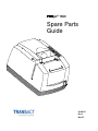
Spare Parts
Guide
20-06371
Rev J
Nov-07
Revision J
Rev A
Rev C
Rev D
Rev E
Rev F
Rev G
Rev H
Rev J
Initial Release.
Pg 33 updated item #2 p/n
Pg 26 added item #28 & 29
Pg 2 updated view & item #’s in chart to only show complete Interface Bd/Bracket Assemblies/Kits as purchased
Pg 28 added item #24 (Driveframe Bearing)
Pg 28 updated item #1 p/n (Screw); Pg 6 removed “buzzer” option
Pg 22 updated item #11 p/n
Added RoHS part numbers to the Spare Parts Lists
NOTICE TO ALL PERSONS RECEIVING THIS DOCUMENT:
The information in this document is subject to change without notice. No part of this document may be reproduced,
stored or transmitted in any form or by any means, electronic or mechanical, for any purpose, without the express
written permission of TransAct Technologies, Inc. ("TransAct"). This document is the property of and contains
information that is both confidential and proprietary to TransAct. Recipient shall not disclose any portion of this
document to any third party.
TRANSACT DOES NOT ASSUME ANY LIABILITY FOR DAMAGES INCURRED, DIRECTLY OR
INDIRECTLY, FROM ANY ERRORS, OMISSIONS OR DISCREPANCIES IN THE INFORMATION
CONTAINED IN THIS DOCUMENT.
Some of the product names mentioned herein are used for identification purposes only and may be trademarks and/or
registered trademarks of their respective companies.
TransAct, PowerPocket, Magnetec, Insta-Load, POSjet, Ithaca, 50Plus, BANKjet and "Made to Order. Built to Last"
are registered trademarks and KITCHENjet is a trademark of TransAct Technologies, Inc.
© 2007 TransAct Technologies, Inc. All rights reserved.
Revision J, November 2007
Printed in USA.
The POSjet® 1500 Printer complies with the limits for a Class B computing device in accordance with the
specifications in Part 15 of FCC rules. These regulations are designed to minimize radio frequency interference
during installation; however, there is no guarantee that radio or television interference will not occur during any
particular installation. Interference can be determined by turning the equipment off and on while the radio or
television is on. If the printer causes interference to radio or television reception, try to correct the interference by
one or more of the following measures:
•
•
•
Reorient the radio or television receiving antenna
Relocate the printer with respect to the receiver
Plug the printer and receiver into different circuits
If necessary, the user should consult their dealer or an experienced radio/television technician for additional
suggestions. The user may find the following booklet prepared by the Federal Communications Commission helpful:
How to Identify and Resolve Radio/TV Interference Problems. This booklet is available from the US Government
Printing Office, Washington, DC 20402. Ask for stock number 004-000-00345-4.
The POSjet® 1500 Printer does not exceed Class A limits for radio noise emissions from digital apparatus set out in
the Radio Interference Regulations of the Canadian Department of Communications.
EMI:
Safety:
FCC Class B
UL (US)
CUL (Canada)
CE Marking:
Safety:
Other:
CLASS B: EN55022, EN50081-1 (optional)
TUV
CB Certificate
Revision J
Monday through Friday, 8 A.M. to 8 P.M. Eastern Standard Time (excluding holidays). To obtain Technical
Support, call: TransAct at (607) 257-8901, or (877) 7-ITHACA.
TransAct Technologies Incorporated has a full service organization to meet your printer service and repair
requirements. If your printer needs service, you can directly contact TransAct at (607) 257-8901 or
(877) 7-ITHACA for a return authorization. International customers should contact their distributor for services.
TransAct offers the following service programs to meet your needs.
•
•
•
•
Extended Warranty
Depot Repair
Maintenance Contract
Internet Support
Please have the following information at hand:
1.
2.
3.
4.
5.
6.
The Model Number and Serial Number.
A list of any other peripheral devices attached to the same port as the printer.
The application software, operating system, and network you are using.
A copy of your printer’s Configuration Settings.
What happened, and what you were doing when the problem occurred.
How you tried to solve the problem.
TransAct’s POSjet® 1500 Printers come with a standard 24-month warranty that commences upon shipment from
factory, and covers parts and labor. An optional warranty, covering both parts and labor for an additional 12 months,
may be purchased separately. Repairs are warranted for 90 days from the date of repair or for the balance of the
original warranty period, whichever is greater.
!
"
If the technical support person determines that the printer should be serviced at our facility, and you want to return
the printer for repair, a Returned Materials Authorization (RMA) number must be issued before returning the printer.
Prepare the printer being returned for repair as follows:
1.
2.
3.
4.
Remove and discard ink cartridges.
Pack the printer to be returned in the original packing material. Packing items may be purchased from
TransAct's Ithaca Facility.
Return only the accessories that a Support Technician asks you to include.
Write the RMA number clearly on the outside of the box.
"
Never ship a printer with any ink cartridge(s) installed. Be sure to save the packing materials in the
event that you need to send the printer in for servicing. TransAct Technologies is not responsible for damaged return
items that are not packaged in original shipping material.
Revision J
#
$
%
www.transact-tech.com
TransAct Technologies Inc. maintains an Internet web site with content devoted to product support. Within the
Technical Support section you can find the most current versions of the Operator’s Guide and Programmer’s Guide.
1.
Upon entering our web site, you will be brought to the “Welcome to TransAct” screen. This intro page has the
Ithaca Brand listed at the top right. Click on the Ithaca logo.
2.
Locate and click on the technical support button in the green area of the “Welcome to Ithaca” screen.
3.
Use the “Product Info” pulldown box to select the appropriate information for the printer model that you are
using.
"
&'
The Programmer’s Guide is available by down loading it from our web site and is intended for system engineers or
integrators. It does not contain additional information on the Microline emulation. It contains the information to
integrate the POSjet® 1500 Printer with a point-of-sale terminal and to program the terminal to communicate with
the printer in ITHACA, or EPSON modes.
!
•
•
•
•
•
•
•
"
#
$
Start-up Information-Diagnostics and Fault Conditions
Command Descriptions
Character Fonts
Printer Features
Parallel and RS-232 Interface Information
Communications and Buffers
Command Code Reference Tables
Revision J
"
Contact TransAct for information about the POSjet® 1500 Printer and how it works with your system. For
information on international distribution, visit our web site at www.transact-tech.com. Contact the TransAct’s Sales
and Technical Support Departments at the following address and telephone or fax numbers.
Receive technical support, order documentation, request additional information, or send in a printer for service.
Order supplies, receive more product information, or order product brochures.
TransAct Technologies Incorporated
Ithaca Facility
20 Bomax Drive
Ithaca, NY 14850 USA
TransAct Technologies
World Gaming Headquarters
& Western Regional Repair Center
6700 Paradise Road
Suite D
Las Vegas, NV 89119 USA
Telephone
Main fax
Sales fax
Technical Support fax
Web site
(877) 7-ITHACA or (607) 257-8901
(607) 257-8922
(607) 257-3868
(607) 257-3911
www.transact-tech.com
Revision J
"
(
%
#
&&&&&&&&&&&&&&&&&&&&&&&&&&&&&&&&&&&&&&&&&&&&&&&&&&&&&&&&&&&&&&&&
&&&&&&&&&&&&&&&&&&&&&&&&&&&&&&&&&&&&&&&&&&&&&&&&&&&&&
&&&&&&&&&&&&&&&&&&&&&&&&&&&&&&&&
&&&&&&&&&&&&&&&&&&&&&&&&&&&&&&&&
&&&&&&&&&&&&&&&&&&&&& '
Standard Features............................................................................................................................................................................................................... 6
Optional Features ............................................................................................................................................................................................................... 6
Additional Supported devices and tools ............................................................................................................................................................................. 7
Drivers and Utilities Available........................................................................................................................................................................................... 7
Optional Printer Configurations ......................................................................................................................................................................................... 7
Supported Emulations ........................................................................................................................................................................................................ 7
Printer Dimensions............................................................................................................................................................................................................. 8
Environmental Conditions ................................................................................................................................................................................................. 9
Relative Humidity .............................................................................................................................................................................................................. 9
Reliability........................................................................................................................................................................................................................... 9
Power Requirements .......................................................................................................................................................................................................... 9
Printing Specifications ..................................................................................................................................................................................................... 10
Auto-cutter (Partial Cut Option) ...................................................................................................................................................................................... 10
Sensors ............................................................................................................................................................................................................................. 10
Media Specifications........................................................................................................................................................................................................ 11
Receipt Paper (one-ply receipt) ........................................................................................................................................................................................ 11
Validation Form Requirements ........................................................................................................................................................................................ 11
Electrical Specifications................................................................................................................................................................................................... 11
&&&&&&&&&&&&&&&&&&&&&&&&&&&&&&&&&&&&&&&&&&&&&&&&&&&&&&&&&&&&&&&&
&&&&&&&&&&&&&&&&&&&&&&&&&&&&&&&&&&&&&&&&&&&&&&&&&&&&&&&&&&&&&&&&&&&&&&&&&&&&&&&&&&&&&&&&&&&&&&&&
&&&&&&&&&&&&&&&&&&&&&&&&&&&&&&&&&&&&&&&&&&&&&&&&&&&&&&&&&&&&&&&&&&&&&&&&&&&&&&&&&&&&&&&&&&&&&&&&
&&&&&&&&&&&&&&&&&&&&&&&&&&&&&&&&&&&&&&&&&&&&&&&&&&&&&&&&&&&&&&&&&&
&&&&&&&&&&&&&&&&&&&&&&&&&&&&&&&&&& (
Periodic Checks ............................................................................................................................................................................................................... 12
Making Adjustments ........................................................................................................................................................................................................ 12
Adjusting the Carriage Belt Tensioner ............................................................................................................................................................................. 13
)*
+
) *&&&&&&&&&&&&&&&&&&&&&&&&&&&&&&&&
* &&&&&&&&&&&&&&&&&&&&&&&&&&&&&&&&&&&&&&&&&&&&&&&&&&&&&&&&&&&&&&&&
&&&&&&&&&&&&&&&&&&&&&&&&&&&&&&&&&&&&&&&&&&&&&&&&&&&&&&&&&&&&&&&&&&&&&&&&&&&&&&&&&&&&&&&&&&&&&&&&
&&&&&&&&&&&&&&&&&&&&&&&&&&&&&&&&&&&&&&&&&&&&&&&&&&&&&&&&&&&&&&&&&&&&&&&&&&&&&&&&&&&&&&&&&&&&&&&&
&&&&&&&&&&&&&&&&&&&&&&&&&&&&&&&&&&&&&&&&&&&&&&&&&&&&&&&&&&&&&&&&&&&&&&&&&&
&&&&&&&&&&&&&&&&&&&&&&&&&&&&&&&&&&&&&&&&&& ,
Precautions for Disassembly ............................................................................................................................................................................................ 14
DIsconnecting the Power Cord......................................................................................................................................................................................... 15
Disconnecting the Communication Cable........................................................................................................................................................................ 15
Disconnecting the Cash Drawer Cables ........................................................................................................................................................................... 16
Removing the Printer Assembly (Midframe) (from Cabinet Base) .................................................................................................................................. 17
Removing the Knife Assembly......................................................................................................................................................................................... 18
- &&&&&&&&&&&&&&&&&&&&&&&&&&&&&&&&&&&&&&&&&&&&&&&&&&&&&&&&&&&&&&&&
&&&&&&&&&&&&&&&&&&&&&&&&&&&&&&&&&&&&&&&&&&&&&&&&&&&&&&&&&&&&&&&&&&&&&&&&&&&&&&&&&&&&&&&&&&&&&&&&
&&&&&&&&&&&&&&&&&&&&&&&&&&&&&&&&&&&&&&&&&&&&&&&&&&&&&&&&&&&&&&&&&&&&&&&&&&&&&&&&&&&&&&&&&&&&&&&&
&&&&&&&&&&&&&&&&&&&&&&&&&&&&&&&&&&&&&&&&&&&&&&&&&&&&&&&&&&&&&&&&&&&&&&&&&&&&&&&&&&&&&&&&&&&&
&&&&&&&&&&&&&&&&&&&&&&&&&&&&&&&&&&&&&&&&&&&&&&&&&&&&&&&&&&&& .
Packing Materials/Publications........................................................................................................................................................................................ 19
Printer Assembly.............................................................................................................................................................................................................. 20
Mechanism Assembly (stage 3)........................................................................................................................................................................................ 22
Cabinet Base Assembly.................................................................................................................................................................................................... 23
Paper Low Option Assembly............................................................................................................................................................................................ 24
Mechanism Assembly (stage 2)........................................................................................................................................................................................ 25
.......................................................................................................................................................................................... Error! Bookmark not defined.
Drive Support Assembly .................................................................................................................................................................................................. 27
Mechanism Assembly (stage 1)........................................................................................................................................................................................ 29
Mechanism Frame Assembly ........................................................................................................................................................................................... 30
Carriage Assembly ........................................................................................................................................................................................................... 31
Replacement Carriage Assembly (1 Cartridge) ................................................................................................................................................................ 32
Power Supply ................................................................................................................................................................................................................... 33
/
&&&&&&&&&&&&&&&&&&&&&&&&&&&&&&&&&&&&&&&&&&&&&&&&&&&&&&&&&&&&&&&&
&&&&&&&&&&&&&&&&&&&&&&&&&&&&&&&&&&&&&&&&&&&&&&&&&&&&&&&&&&&&&&&&&&&&&&&&&&&&&&&&&&&&&&&&&&&&&&&&
&&&&&&&&&&&&&&&&&&&&&&&&&&&&&&&&&&&&&&&&&&&&&&&&&&&&&&&&&&&&&&&&&&&&&&&&&&&&&&&&&&&&&&&&&&&&&&&&
&&&&&&&&&&&&&&&&&&&&&&&&&&&&&&&&&&&&&&&&&&&&&&&&&&&&&&&&&&&&&&&&&
&&&&&&&&&&&&&&&&&&&&&&&&&&&&&&&&& 0,
Ink Cartridges................................................................................................................................................................................................................... 34
Cables............................................................................................................................................................................................................................... 34
Drivers Available ............................................................................................................................................................................................................. 34
Revision J
'
POSjet® 1500 Features and Specifications
%
•
•
•
•
•
•
•
•
•
•
•
•
•
•
•
•
•
•
•
•
Print Speed: 12 lps. at 10 char. per line
Print Resolution: Max. 208 dpi. Horizontal, 96 dpi. Vertical
Simple Snap-In, No-Mess Cartridges with Fast-Drying Ink
Standard Warranty: Two Years (Extended Maintenance Plan Available)
Insta-Load® Automatic Paper Loading
Cash Drawer Drivers: Dual with Status (Single RJ12)
Font Selections: Draft, Large Draft and Near Letter Quality
Selectable Printing Features of Bold, Italics, Size Scaling and Rotated
Emulations: Ithaca/IBM, Epson ESC/POS, TM-U325
APA and Epson Bit Map Graphics
Data Buffer: 8K (Adjustable)
208K Non-Volatile Flash for Multiple Character Sets, Bit Images and Electronic Journal
Bar Codes: Code 39, Code 93, Interleaved 2 of 5, UPC-A and UPC-E, EAN8 and EAN13, Code 128
65 Language Character Sets Supported (EURO Character Included)
Self Diagnostics
Remote Statistics
Paper Out and Ink Low Detection and Indicators
Software Developer’s Toolkit Available
Top Drop-in Forms Insertion with Programmable Top of Form
Independent Validation
•
•
•
•
%
Auto-cutter (partial cut)
Adjustable paper low
Two-Color Printing
Univeral Power Supply and PowerPocket®
Revision J
1
"
2
#
The POSjet® 1500 will be supported by various PC based tools. These tools include but are not limited to the
following:
32
PJColor is a program that will allow images and picture to be processed so they can work with the printer.
3
PJTerminal is a test application that is used to verify communications to the printer.
34
PJBootload is a program that is used to replace or update the printer’s firmware.
/
2
#
Ithaca Config is a program that is used to replace or update the printer’s configuration settings.
+ "
5
"
)
POSjet® 1500 Drivers and Utilities can be downloaded from our web site, or call our Technical Support Department
to request a Software Developer’s Toolkit (CD-ROM).
/
2
"
5
*
POSjet Image Converter (PJColor) is a tool to help develop graphic images to use as logos and coupons on the
printer. It will read and convert images to a format suitable for printing on the POSjet® 1500 printer. It will allow
you to preview the image and adjust the colors prior to printing. It will also allow the images to be stored in the
printer's User Store.
3
5
*
PJTerminal is a tool that has been developed to allow you to interactively send commands to and get responses from
the printer.
2
2
2
#
#
All POSjet® 1500 ink cartridge configurations are factory installed options.
2
The single color configuration is provided with a single ink cartridge. It cannot be upgraded for two-color operation.
$ 62
7
*
The two color ready configuration is equipped with a single ink cartridge but can be easily upgraded to two-color
operation simply by installing a second ink cartridge.
$ 62
Two-color configuration requires that two cartridges be installed in the carriage. If one of the cartridges is black, it
must be installed in the left carriage position.
/ 2- 2
28
/
Revision J
9
+
Figure 1 Printer Dimensions
Width
Depth
Height
Without Knife
6.75"
(172 mm)
9.75"
(248 mm)
5.92"
(151 mm)
With Knife
6.75"
(172 mm)
9.75"
(248 mm)
6.44"
(164 mm)
Weight:
Shipping:
approx. 6 lbs. (2.7 kg)
approx. 8 lbs. (3.6 kg)
Interface
Serial RS-232C
Parallel IEEE1284
USB
Bi-directional- Ready/Busy or XON/XOFF (9-pin D-shell or 25-pin D-shell)
Bi-directional- transmit/receive/ground (25-pin D-shell or 36-pin Centronics)
Version 1.1
Revision J
.
"
2
The POSjet® 1500 is designed to be placed on point-of-sale terminals, counter tops, or any other flat, stable surface
that can support the weight of the printer (about 6 lbs. or 2.7 kg). Be aware that the environmental conditions of the
location where you place the printer will have an effect on the printer’s performance and longevity. The printer will
run its best when stored and operated in an environment that meets the following temperature and humidity
conditions.
Typical Operating Range:
*Extended Operating Range:
Storage:
Shipping:
10°C to 40°C / 50°F to 104°F
0°C to 45°C / 32°F to 113°F+
-10°C to 60°C / 14°F to 140°F
-40°C to 70°C / -40°F to 158°F
* Exposure to high or low temperatures for periods of greater than 48 hours will lead to significantly reduced
cartridge life. The Typical Operating Range provides full printer reliability. The Extended Operating Range may
degrade the reliability of the printer and life of the cartridge.
7
" :
Operating:
Storage:
Shipping:
*
10% to 90% RH (non-condensing)
10% to 90% RH (non-condensing)
5% to 90% RH (non-condensing)
7 ) *
Printer Life
Mean time between failures: (without cartridge):
Average cartridge life (Average 16 dots/character):
Autocutter option (partial cut):
Mean time to repair:
Validation Cycles :
$
+2
10,000,000 print lines
28,000 hours
7.0 million characters
1 million cuts
15 minutes
1 million cycles
7;
$
<
Earth Ground
+24 Vo lt Supply
Ground (+24 V dc)
Supply voltage:
Supply Current:
2
$
24 Vdc ± 10%
1.0Amps
<
Supply Voltage:
Frequency:
Supply Current:
100-240 Vac
50/60 Hz
.5 Amps maximum
The POSjet® 1500 Printer is designed to be AC self-powered in domestic and international markets. The printer is
equipped with a detachable universal input power supply that is designed to operate worldwide without modification.
The power supply is a self-contained integrated switching power supply. The internal fuse (F1) located on the power
supply will blow if the supply has an internal fault. The power supply has the following outputs, +5 VDC, +12 VDC,
and +40 VDC, and an alarm signal input. The AC input connector and power switch are located on the back of the
printer.
Revision J
#
Printing method:
Cartridge arrangement:
Printing directions:
Paper feed pitch:
Validation Type:
# Validation lines:
Receipt print zone (maximum):
Validation print zone:
Thermal ink jet
12 nozzle
Bi-directional, logic seeking
Default - 0.125" (1/8" or 3.175 mm)
Independent
Max. 9 lines (1.53") @ 6 lpi. 12 lines @ 8 lpi.
2.5" (63.5 mm)
Refer to “Validation Form Requirements” on page 11.
6
=
2
>
A receipt auto-cutter is an optional feature with all POSjet® 1500 Printers.
Cutter type
Cut to line of print
Cutter life
Tear-off to line of print
Guillotine
1.635" (41.52 mm)
1,000,000 cuts
1.235” (31.4MM)
6
1.635"
0.25"
2.5"
3.0"
Figure 2 Receipt Printable Area
Paper low indicator
Receipt paper out
Paper feed method
Optional Paper Low Sensor (based on paper roll diameter).
About 1.0" (25 mm) of paper remaining
Friction feed
A receipt paper out sensor is provided as a standard feature. It senses when there is approximately one inch of paper
left on the paper roll.
- $
A receipt paper-low sensor is provided as an optional feature. An operator-adjustable paper-low assembly allows the
printer to sense when the paper roll is between 1.42" and 0.885" (36.1mm and 22.5mm) in diameter. It is adjustable
to compensate for various paper core dimensions.
Revision J
#
: $
6
?
/?
2
Print Cartridge Specification
Cartridge arrangement
Vertical dot pitch
Cartridge life
Cartridge Colors
7
= 6 *
Paper width:
Paper roll diameter:
Paper thickness:
Roll paper core outside Dia.
Roll paper core inside Dia.
Roll footage:
<
%
7;
Form thickness-single part:
Form Size (Min):
Form Size (Max):
# Validation lines:
Check Basis weight:
1
HP C6602A
12 vertical nozzles
0.264 mm (0.0104") or 96dpi.
~7.0 M Characters @ 16 dots per Character.
Black, Red, Blue, Green
>
3.0" ± .02" (76mm ± .5mm)
4.0" max (101.6mm max)
.003" - .004" (.07mm - .1mm)
0.82" - 0.85" (20.8 – 21.6 mm) Dia.
0.45" - 0.50" (11.4 – 12.7 mm) Dia.
330 feet - standard grade
300 feet - premium grade
.003" to .0047" (.076 mm. to .119 mm.)
2.75" high x 2.75" long (69.8 mm. x 69.8 mm.)
8.5" high x 11" long (215.9 mm. x 279.4 mm.)
Max. 9 lines (1.53") @ 6 lines per inch
24 lbs.
#
@
$
2
@
$
+2
The POSjet® 1500 Printer is designed to be AC self-powered in domestic and international markets. The printer is
equipped with a detachable universal input power supply that is designed to operate worldwide without modification.
Optionally, the POSjet® 1500 Printer can be operated with an external 24-volt DC power supply.
1
Print Cartridge Specifications are controlled by Hewlett-Packard and are proprietary. Information here is for
reference only.
Revision J
(
General Maintenance Procedures
2
?
Failure to perform periodic checks will eventually create printing inconsistencies and lead to more serious problems.
Refer to the following information for a check list of cleanable items.
•
•
•
•
•
•
Wipe all external plastic components using a cloth and non-corosive cleaner
Remove paper dust from all internal components using compressed air or vacuum
Clean Carriage Shaft
Clean contact areas with alcohol
Remove all paper shavings from knife (if knife is an option)
Clean rubber cartridge wipers with alcohol
?
The following information will answer some commonly asked questions about adjusting the POSjet® 1500. Due to
the POSjet® 1500’s design, the need to adjust components is limited to only two areas that may require periodic
attention. Generally, the time duration between adjustments is dependant on the operational conditions for each unit.
TransAct recommends that all adjustments are made by a service technician who has completed training on the
POSjet® 1500.
Revision J
0
2
4
The POSjet® 1500 uses a drive belt that is adjustable by simply loosening the phillips head screw on the belt
tensioner. An improperly adjusted belt tensioner may cause pre-mature belt wear and/or produce inconsistent
printing. To adjust the belt tensioner:
Figure 3 Adjusting the Belt Tensioner
1.
Open both the front and rear top covers.
2.
Locate the phillip’s head screw on the tensioner and partially loosen until the spring tension returns the belt to
correct position. Slide ink carriage from side to side to ensure that tensioner spring resets itself and immediately
re-tighten screw while holding the Belt Tensioner with your finger to ensure alignment with mechanism frame.
3.
Close both the front and rear top covers.
Revision J
,
Assembly and Disassembly
# +
)*
Before disassembling any part of the printer, be sure the power is turned off. Disconnect the AC power cord, the
communication cable, and the cash drawer cables. Controller board and keypad PC board can be damaged by static
electricity. Observe ESD precautions. Wear a grounded wrist strap, and use a static mat or other protected work
surface. Do not place the printed circuit boards directly on the printer or floor.
*
Using the wrong tools may cause personal injury or damage the printer. Be sure to use the proper tools when
maintaining or servicing the printer. The following list provides the necessary tools to properly maintain the
POSjet® 1500 Printer.
•
•
•
•
•
•
•
•
Screwdrivers
#0 Phillips
#1 Phillips
#2 Phillips
Small Flat Blade Screwdriver
Large Flat Blade Screwdriver
Nut Drivers
Small Needle-Nose Pliers
Revision J
+/
$ 2
The printer must be grounded through the three-prong power connector. Do not use a ground defeating adapter.
1.
Be sure the power switch is turned off.
2.
Disconnect the external AC power source
and the power cord from the power socket
located on the back of the printer.
Figure 4 Disconnecting the Power Cord
+
2
2 )
Depending on the interface your system uses, disconnect either the serial or parallel communication cable from the
connector on the back of the printer.
2 )
Figure 5 Disconnecting the Communication Cable-Serial
1.
Turn the printer and the host system or PC off.
2.
Loosen the two mounting screws on each side of the cable connector.
3.
Disconnect the 9-pin serial interface cable from the connector on the back of the printer.
Revision J
'
2 )
Figure 6 Disconnecting the Communication Cable-Parallel
1.
Turn the printer and the host system or PC off.
2.
Disconnect the 25-pin parallel cable from the connector on the back of the printer.
+
2
+ $
2 )
1.
Turn the printer off.
2.
Disconnect the cash drawer cable to the connectors on the back of the printer.
Figure 7 Disconnecting the Cash Drawer Cables
Revision J
1
7
"
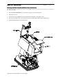
) *= #
>=#
2 )
4 >
The Printer Assembly is held to the cabinet base by 4 phillips head screws located at the front and rear sections of
the Printer Assembly.
1.
Press the
2 < 7 Button to release the rear paper cover from the console.
2.
Open the front cover.
3.
Slowly remove the 4 phillips head screws that hold the mid-frame to the printer’s base.
4.
Disconnect the knife harness, and separate the printer assembly (mid-frame) from the cabinet base.
5.
Unhook the knife harness from the PC Board.
Figure 8 Removing Printer Midframe from Cabinet Base
Revision J
9
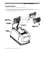
7
"
A #
)*
The Knife Assembly is attached to the Rear Paper Cover of the printer.
1.
2.
3.
Disconnect the knife harness connector and unroute the wires from the wire retention clips.
Unscrew the self-tapping, “middle screw”, to release the knife assembly from the rear paper compartment cover.
Unsnap the knife assembly from the the rear paper cover.
Figure 9 Removing Knife Assembly from the Paper Cover
Revision J
.
Spare Parts List
®
The following spare parts list details the available replacement parts that make up the POSjet 1500 printer. When
selecting parts, be aware that some assemblies have to be purchased at a factory pre-determined breakdown level.
?
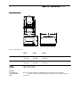
8 )
Figure 10 Packing Materials
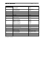
No.
Description (standard parts)
Part Number (History)
1
Foamset-Open Cell
20-03400 (12-01726)
2
Bag-Antistatic Shipping
98-01902
3
Cord-110V Power
Cord-230V Power (Europe)
Cord-240V Power (UK)
Cord-220V Power (AUST)
Cord-230V Power (IND/S. Africa)
Parallel Communication Cable
25-pin Parallel Cable (straight thru)
36-pin Parallel Cable (Centronics)
Serial Communication Cable
PC, 9-pin Female to 9-pin Female
PC, 9-pin femal to 25-pin Female
USB Communication Cable
Cable-USB
98-02174L (98-02174)
98-02175L (98-02175)
98-02176L (98-02176)
98-02178L (98-02178)
98-02179L (98-02179)
4
Cartridge-HP Black
Cartridge-HP Red
Cartridge-HP Blue
Cartridge-HP Green
98-01570
98-01571
98-01572
98-01573
5
Carton-Open Cell Foam
12-01727
6
Sheet-Quick Reference
20-03395
7
Wedge-Shipping
20-03570
Table 1 Packing Materials Parts List
• Not available as a spare part
253-9800007
253-9800002
10-2020
10-2021
98-04322 (98-04301,98-01992)
Revision J
(
)*
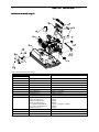
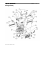
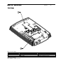
Figure 11 Printer Assembly
Revision J
(
No.
Description (standard parts)
Part Number (History)
1
Cover-Lt. Tan Paper
Cover-Dk. Gray Paper
Cover-Black Paper
20-02760 (20-03636, 20-00507)
20-02761
20-02762
2
Cover-Lt. Tan Autocut Paper
Cover-Dk. Gray Autocut Paper
Cover-Black Autocut Paper
20-04631 (20-00508)
20-04632
20-04633
3
Spring-Paper Feed
12-01660
4
Hinge-Cover
12-01629
6
Assy-PJ1500 Knife
12-05218L • (2-05218, R20-03417)
7
Bracket-Hinge
12-01628
8
Pin-Hinge
12-01630
9
Spring-Cover (w/knife)
Spring-Cover (w/o knife)
20-02731
20-02749
10
Overlay-LT Tan LED Button
Overlay-Dk. Gray LED Button
20-02850
20-02851
11
Midframe-P.P. LT Tan (POSjet)
Midframe-P.P. LT Tan (Bankjet)
Midframe-P.P. Lt. Tan (Oki)
Midframe-P.P. Dk. Gray (POSjet)
Midframe-P.P. LT Tan (no logo)
Midframe-P.P. Dk. Gray (Bankjet)
Midframe-P.P. Black (Bankjet)
R20-00509
R20-03517
R20-03625
R20-00513
R20-04228
20-04239
20-05401
12
Screw-6-20x.375 PHPS PHD THD-CUT
98-2052
13
Cover-Knife
20-04630 (20-02755)
14
Button-PJ1500 Release (Lt. Tan)
Button-PJ1500 Release (Dk. Gray)
20-02745
20-02746
15
Assy-Stage 3 Mechanism
20-03418
16
Roller-Paper Load
12-02481
17
Nut-M3 Hex w/Lockwasher
98-0621
18
Cover-P.P. LT Tan Cartridge
Cover-P.P. Dk. Gray Cartridge
Cover-P.P. Black Cartridge
20-00510 (20-02710, 20-00510)
20-00514 (20-02711, 20-00514)
20-05402
19
Screw-#4 Plastic THD Forming
98-7608
20
Spring-Compression
20-03600
21
Assy-Complete Knife (includes items 3,5,6,12,13,16,17,19)
20-05763L (20-05763)
5
Table 2 Printer Assembly Parts List
• Not available as a spare part
Revision J
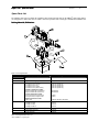
((
) *=
0>
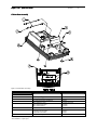
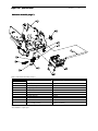
Figure 12 Mechanism Assembly (stage 3)
No.
Description (standard parts)
Part Number (History)
1
Plate-Keypad
20-03158
2
Assy-Keypad PCB
20-03348
3
Screw-M3x6 PHPS PHD
98-0611
4
Harness-Paper Low
12-02211l (12-02211)
5
Assy-Stage 2 Mechanism
20-03415 •
6
Assy-Controller PCB
20-04259L (20-04259, 20-03266 & 20-04276)
7
CAP-Actuator
12-03434
8
Assy-Cabinet Base
20-03416L • (20-03416)
9
Bearing-Carriage
20-04688 (12-01509)
10
Screw-Jack
98-02383
11
Kit-9 pin Serial Interface
Kit-25 pin Serial Interface
Kit-25 pin Parallel Interface
Kit-36 pin Parallel Interface
Assy-Standard USB Bd/Bracket
Assy-Powered USB Bd/Bracket
Kit-Ethernet Interface
12-00293
12-00294
12-00295
12-00296
12-07557L (12-05985L, 12-00309)
12-05984L
12-05070
12
Screw-M3x6 PHPS PHD
98-0611
13
Shunt-10 Position
98-02251
14
Bracket-Keypad
Table 3 Cabinet Base Assembly Parts List
12-03165
• Not available as a spare part
Revision J
2 )
4
)*
Figure 13 Cabinet Base Assembly
No.
Description (optional parts)
Part Number (History)
1
Rod-Roller Support
15-9797
2
Roller-Paper Supply
15-9798
3
Guide-Lower Slip
20-03163
4
Screw-6-20x.375 Phps Phd Thd-Cut
98-2052
5
Base-Cabinet (Lt. Tan)
Base-Cabinet (Dk. Gray)
Base-Cabinet (Black)
12-04385 (12-03330)
12-04386
12-04388
6
Foot-Rubber
06-0553
7
Label-Epson Cash Drawer
Label-Ithaca Cash Drawer
Label-Star Cash Drawer
90-9933 •
90-9934 •
90-9935 •
8
Label-Blank Polyester
98-7976 •
Table 4 Cabinet Base Assembly Parts List
• Not available as a spare part
(0
Revision J
(,
-$
)*
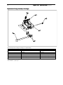
Figure 14 Paper Low Option Assembly
No.
Description
Part Number (History)
1
Screw-6-20X1.5 Pl Thd Form
98-01589
2
Bracket-Paper Low
12-01551
3
Spring-Paper Low Comp
98-01593
4
Ball-Paper Low
98-01594
5
Switch-Momentary Lever
98-02098L (98-02098)
Table 5 Paper Low Option Assembly Parts List
• Not available as a spare part
Revision J
) *=
(>
Figure 15 Mechanism Assembly (stage 2)
(
Revision J
('
No.
Description
Part Number (History)
1
Interlock-Cover Open
12-01633
2
Spring-Compression
98-9124
3
Assy-Std. Validation
Assy-Autocut Validation
20-06943L (20-06943, 20-04376, 20-03412)
20-06942L (20-06942, 20-04375, 20-03406)
4
Nut-M3 Hex w/Lockwasher
98-0621
5
Retainer-E Ring .125 Dia.
520-9800002
6
Assy-STD Drive Support
Assy-Autocut Drive Support
R20-03410
20-03404
7
Motor-Step 35mm 7.5° w/pinion
98-03208L (98-03208)
8
Motor-Step 7.5° w/pinion
98-04311L (98-04311, 98-01706)
9
Screw-#4 Plastic Thd. Forming
98-7608
10
Belt-Timing 95T/.080 Pitch
98-03162
11
Keeper-E Ring .156 Dia.
98-8223
12
Gear-Combo Pulley 48/12T
20-03154
13
Bearing-Platen
12-01552
14
Retainer-E Ring .25 Dia.
520-9800006
15
Assy-Stage 1 Mechanism
20-03414 •
16
Gear-Compound 14/48T
20-03150
17
Gear-Compound 18/48T
20-03151
18
Gear-18T Platen Drive
20-03145
19
Bearing-platen
12-01552
20
Screw-6-20x.375
98-2052
21
Wire-Retainer
98-9187
22
Isolator
12-03303
23
Clip-Retaining
98-7970
24
Rod-Actuator
12-04697 (R12-03495)
25
Screw-M3x6 Phps Phd
98-0611
26
Clamp-Cable
98-04621 (98-03171)
27
Washer-#4 Flat
527-9800002
28
Cap-Actuator
20-04754
29
Washer-#6 Flat
069477-06C5
Table 6 Mechanism Assembly Parts List (stage 2)
• Not available as a spare part
Revision J
+ "
)*
Figure 16 Drive Support Assembly
(1
Revision J
(9
No.
Description
Part Number (History)
1
Screw-#6-18 X 1/4 TAP PHD PHPS
M067883-03 (98-04160, 98-2052)
2
Guide-Top Receipt
20-04432 (20-02542)
3
Roller-Pressure
12-01506 •
4
Assy-Platen
12-03311 •
5
Disk-Wiper
20-03176
6
Wiper-Cartridge
98-03326
7
Screw-#2 Plastic Thd Forming
98-02592 •
8
Switch-Momentary Lever
98-02098L (98-02098)
9
Na
Na
10
Arm-Paper Out
12-01547
11
Roller-Receipt
12-05129 (12-01521)
12
Guide-Std Receipt
Guide-Receipt w/Knife
20-04718L (20-04165,20-02557) •
20-04719L (20-04166, 20-02553) •
13
Strap-Ground
20-03558 •
14
Spring-Paper Drive
20-02550 •
15
Frame-Drive
20-02525 •
16
Shaft-Wiper
12-01531 •
17
Arm-Wiper
20-04724 • (20-03164)
18
Screw-4/40
98-01595
19
Spittoon
12-01548 •
20
Guide-Upper Slip
20-03157 •
21
Spring-Wiper Extension
98-03601 (98-01592)
22
Arm-Solenoid
12-01529 •
23
Assy-Solenoid
12-02213l (12-02213)
24
Bearing-Driveframe
20-04716
Table 7 Drive Support Assembly Parts List
• Not available as a spare part
Revision J
) *=
>
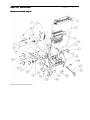
Figure 17 Mechanism Assembly (stage 1)
No.
Description
Part Number (History)
1
Assembly-Mech Frame
20-03407 •
2
CAM-Eccentric
12-03497
3
Screw-M3x6, Phillips PHD
98-0897
4
Pulley-Flanged
12-02475
5
Tensioner-Belt
12-01532
6
Spring-Tensioner Comp
98-01591
7
Shaft-Carriage
20-03149
8
Plate-Belt Tensioner
12-01533
9
Pin-Idler Tensioner
98-01520
10
Washer-Felt
12-01549
11
Assy-2 Cartridge Carriage
Assy-1 Cartridge Carriage
20-03411L (20-03411)
20-03405L (20-03405)
Table 8 Mechanism Assembly (stage 1) Parts List
• Not available as a spare part
(.
Revision J
0
%
)*
Figure 18 Mechanism Frame Assembly
No.
Description
Part Number (History)
1
Assy-Main Frame
20-04661 (20-03569)
2
Screw-M3x6mm PHPS PHD
98-0611
3
Nut-M3 Hex w/Lockwasher
98-0621
4
Assy-Carriage Motor
20-04658L (20-04658, 20-04555, 20-03402)
5
Harness-Head POS Sensor
12-02212L (12-02212)
6
Nut-M3 Hex w/Lockwasher
98-0621
7
Spacer-Motor
20-02870
Table 9 Mechanism Frame Assembly Parts List
• Not available as a spare part order
Revision J
2
)*
Figure 19 Replacement Carriage Assembly
No.
Description
Part Number (History)
1
Assy-Repl Carriage (2 cartridge)
Assy-Repl Carriage (1 cartridge)
20-03409
20-03403
2
Belt-132 Tooth
98-01542
3
Screw-#4 Plastic Thd Forming
98-7608
4
Washer-#4 .032 Thk Flat
527-9800002
Table 10 Carriage Assembly Parts List
• Not available as a spare part order
0
Revision J
0(
7
2
) *= 2
>
Figure 20 Replacement Carriage Assembly (ref. Part #20-03403)
No.
Description
Part Number (History)
1
Cushion-Head Cable
20-03148 •
2
Carriage
20-03140 •
3
Pivot Pin-Latch
12-01539 •
4
Head Cable
12-01897L • (12-01897)
5
Assy-Carriage Latch
12-02298L • (98-02098)
6
Retainer-Head Cable
12-02423 •
Table 11 Replacement Carriage Assembly Parts List
• Not available as a spare part
Revision J
$
*
Figure 21 Power Supply
No.
Description
Part Number (History)
1
Support-Power Supply (Black)
12-01624 (12-01625)
2
Power Supply
98-06509L (98-06500, 98-02250)
Table 12 Power Supply
• Not available as a spare part order
00
Revision J
0,
Ordering Genuine Ithaca Supplies
Genuine Ithaca Supplies can be ordered directly from the TransAct website (www.transact-tech.com) or by using our
toll free telephone number within the US: (877) 7-ITHACA. When calling, please ask for the Consumables Sales
Department.
Consumable Kits
Stock Number
12 rolls paper/1 Blk. Ink Cartridge (Standard Grade)
20 rolls paper/1 Blk. Ink Cartridge (Standard Grade)
12 rolls paper/1 Blk. Ink Cartridge (Premium Grade)
20 rolls paper/1 Blk. Ink Cartridge (Premium Grade)
100-03429
100-03430
98-03508
98-03509
Table 13 Paper Ordering Information
Receipt Paper
Type
Dimensions
Stock Number
24 Roll Case
32 Roll Case
24 Roll Case
(Ithaca Inkjet 295S)
(Ithaca Inkjet 300P)
(Ithaca Inkjet 300P)
See page 11.
98-02022
98-03505
98-06697
Table 14 Paper Ordering Information
/?2
3 Pack Cartridges
Supplier
Stock Number
3 Pack Black
Transact’s Ithaca Facility
100-02347
3 Pack Red
Transact’s Ithaca Facility
100-02349
3 Pack Blue
Transact’s Ithaca Facility
100-02353
3 Pack Green
Transact’s Ithaca Facility
100-02351
6 Pack Cartridges
Supplier
Stock Number
6 Pack Black
Transact’s Ithaca Facility
100-02348
6 Pack Red
Transact’s Ithaca Facility
100-02350
6 Pack Blue
Transact’s Ithaca Facility
100-02354
6 Pack Green
Transact’s Ithaca Facility
100-02352
Table 15 Ink Cartridge Ordering Information
2 )
Cables
Stock Number
110V Power Cable (USA)
98-02174L
220V Power Cable (Australia)
98-02178L
230V Power Cable (International)
98-02175L
230V Power Cable (IND/South Africa)
98-02179L
240V Power Cable (UK)
98-02176L
Parallel Communication Cable
253-9800007
253-9800002
25-pin male to 25-pin male
36-pin Centronics to 25-pin male
Serial Communication Cable
10-2020
10-2021
9-pin Female to 9-pin Female
9-pin Female to 25-pin Female
Table 16 Cables Ordering Information
Domestic and International power cables available. Call for more information
+ "
"
)
Windows® 95/98/Me Print Driver and Documentation
Windows® 2000/NT 4.0 Print Driver and Documentation
OPOS Print Driver Manual (includes diskettes)
Software Developer’s Toolkit
(CD-ROM)
100-9167
100-9170
100-9732
100-02440