1
®
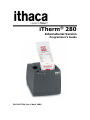
iTherm 280
International Version
Programmer’s Guide
PN 28-07764, Rev C April 2009
This page intentionally left blank
Change History
Rev A Initial Release
Rev B
Added Periodic status back
Added user defined code page description.
Added double byte code page support
Rev C
Revised Page mode section
Added several internal code pages
Added Multi-byte Code page support
28-07764
Rev C
Sept 2007
April 2009
Page 1
Federal Communications Commission Radio
Frequency
Interference Statement
®
The iTherm 280 Printer complies with the limits for a Class A computing device in
accordance with the specifications in Part 15 of FCC rules. These regulations are
designed to minimize radio frequency interference during installation; however, there is
no guarantee that radio or television interference will not occur during any particular
installation. Interference can be determined by turning the equipment off and on while
the radio or television is on. If the printer causes interference to radio or television
reception, try to correct the interference by one or more of the following measures:
1. Reorient the radio or television receiving antenna
2. Relocate the printer with respect to the receiver
3. Plug the printer and receiver into different circuits
If necessary, the user should consult their dealer or an experienced radio/television
technician for additional suggestions. The user may find the following booklet prepared
by the Federal Communications Commission helpful: How to Identify and Resolve
Radio/TV Interference Problems. This booklet is available from the US Government
Printing Office, Washington, DC 20402. Ask for stock number 004-000-00345-4.
Canadian Department of Communications Radio
Interference
Statement
®
The iTherm 280 Printer does not exceed Class A limits for radio noise emissions from
digital apparatus set out in the Radio Interference Regulations of the Canadian
Department of Communications.
Regulatory Compliance
FCC Class A
ULc
CE Mark
UL 1950
TUV
Page 2
Rev C
28-07764
Disclaimer
NOTICE TO ALL PERSONS RECEIVING THIS DOCUMENT:
The information in this document is subject to change without notice. No part of this
document may be reproduced, stored or transmitted in any form or by any means,
electronic or mechanical, for any purpose, without the express written permission of
TransAct Technologies, Inc. ("TransAct"). This document is the property of and contains
information that is both confidential and proprietary to TransAct. Recipient shall not
disclose any portion of this document to any third party.
TRANSACT DOES NOT ASSUME ANY LIABILITY FOR DAMAGES INCURRED,
DIRECTLY OR INDIRECTLY, FROM ANY ERRORS, OMISSIONS OR
DISCREPANCIES IN THE INFORMATION CONTAINED IN THIS DOCUMENT.
TransAct cannot guarantee that changes in software and equipment made by other
manufacturers, and referred to in this publication, do not affect the applicability of
information in this publication.
Copyright
© 2007-2009 TransAct Technologies, Inc. All rights reserved.
Revision Level C
April 2009
Printed in USA
Trademarks
Some of the product names mentioned herein are used for identification purposes only
and may be trademarks and/or registered trademarks of their respective companies.
BANKjet, 50Plus, Insta-Load, Ithaca, "Made to Order. Built to Last", Magnetec, PcOS,
POSjet, PowerPocket, iTherm and TransAct are registered trademarks and Epic 950,
Flex-Zone, imPort, ithaColor, KITCHENjet, Momentum, QDT and TicketBurst are
trademarks of TransAct Technologies, Inc.
28-07764
Rev C
Page 3
Table of Contents
Change History ............................................................................................................... 1
Federal Communications Commission Radio Frequency Interference Statement ........... 2
Canadian Department of Communications Radio Interference Statement ....................... 2
Regulatory Compliance ................................................................................................... 2
Disclaimer ....................................................................................................................... 3
Copyright ........................................................................................................................ 3
Trademarks..................................................................................................................... 3
Table of Contents............................................................................................................ 4
Figures............................................................................................................................ 9
Tables ............................................................................................................................. 9
®
Introducing your iTherm 280 Printer ........... 11
About your iTherm® 280 Printer..................................................................................... 13
Who Should Read This Guide? ..................................................................................... 14
What Is Included in This Guide? ................................................................................... 14
Warranty Options .......................................................................................................... 14
Technical and Sales support ......................................................................................... 15
On-line Technical Support ..................................................................................... 15
Telephone Technical Support ................................................................................ 15
Return Materials Authorization and Return Policies ............................................... 16
Service Programs .................................................................................................. 16
Sales Support........................................................................................................ 16
Contact Information ............................................................................................... 16
®
iTherm 280 Specifications and Requirements
...................................................................... 19
iTherm® 280 Specifications and Requirements ............................................................. 21
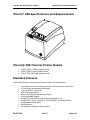
iTherm® 280 Thermal Printer Models ........................................................................... 21
Standard Features ........................................................................................................ 21
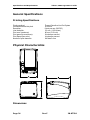
Optional Features ......................................................................................................... 23
General Specifications .................................................................................................. 24
Printing Specifications ........................................................................................... 24
Physical Characteristics ................................................................................................ 24
Dimensions ........................................................................................................... 24
Weight ................................................................................................................... 25
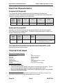
Electrical Characteristics ............................................................................................... 26
Internal AC Powered ............................................................................................. 26
External Powered DC ............................................................................................ 26
Thermal Print Head ....................................................................................................... 26
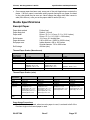
Media Specifications ..................................................................................................... 27
Receipt Paper ....................................................................................................... 27
Buzzer .......................................................................................................................... 29
Cover Interlock .............................................................................................................. 29
Display Pass Through ................................................................................................... 29
Communications Interface............................................................................................. 30
Parallel Interface ................................................................................................... 30
RS-232 Serial Interface ......................................................................................... 31
USB Interface ........................................................................................................ 31
Page 4
Rev C
28-07764
Ethernet 10-Base-T adapter .................................................................................. 32
802.11b Wireless Interface .................................................................................... 32
Cash Drawer ......................................................................................................... 33
Interface Description ............................................................................................. 33
Cash Drawer Pin Assignments .............................................................................. 33
Vertical Wall Mount Kit Option....................................................................................... 35
Setup Procedures .......................................... 37
Verifying the Configuration ............................................................................................ 39
Verify the Communications Interface Card ............................................................ 39
Changing Interface Cards...................................................................................... 39
Removing the Old Interface Card .......................................................................... 39
Cash Drawer Configuration ................................................................................... 40
Configuring the Cash Drawer Interface.................................................................. 40
Installing Cables............................................................................................................ 41
Connecting power ................................................................................................. 41
Connecting Communications Cables ..................................................................... 42
Verify the Firmware Configuration ......................................................................... 43
Installing Paper ............................................................................................................. 43
Printer Drivers and Printer Controls............................................................................... 44
Definitions for terms you will see in this guide: ...................................................... 44
Getting Started – Questions to Ask ............................................................................... 45
Do you want to use USB and simulate a communication port? .............................. 45
Do you want to use an Ethernet interface and simulate a communication port? .... 45
Are you using OPOS (UnifiedPOS/UPOS)? .......................................................... 46
Do you want to print from a Windows application? ................................................ 46
Windows Printer Driver ................................................................................................. 47
PC Hardware ................................................................................................................ 47
GDI ............................................................................................................................... 47
OPOS driver ................................................................................................................. 48
PC Hardware ................................................................................................................ 48
USB driver .................................................................................................................... 49
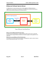
Ethernet Virtual Serial driver ......................................................................................... 50
POSPrinter ActiveX Control (POSPrinter OCX)............................................................. 51
PC Hardware ................................................................................................................ 51
Where to get more information .............................................................................. 52
®
How to Operate the iTherm 280 Printer ....... 53
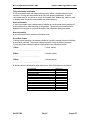
How to Operate the iTherm® 280 Printer ....................................................................... 55
* Button........................................................................................................................ 55
FEED Button ................................................................................................................. 55
Indicator Lights (LED) ................................................................................................... 56
Power Indicator (LED) ........................................................................................... 56
Error Indicator (LED) ............................................................................................. 56
Paper Indicator (LED)............................................................................................ 56
Fault Indicators ............................................................................................................. 56
Testing the Printer Overview ......................................................................................... 58
Using Self-Test, Configuration, and Hex Dump Mode ........................................... 58
Hex-dump Mode.................................................................................................... 60
Level 0 Diagnostics ............................................................................................... 61
Boot Loader Mode ................................................................................................. 61
28-07764
Rev C
Page 5
Configuring Your iTherm® 280 Printer ........... 63
Configuration Mode Overview ....................................................................................... 65
Most Frequent Configuration Incompatibilities ....................................................... 65
How to Change Configuration Settings ......................................................................... 65
Entering into Configuration Mode .......................................................................... 65
Using Configuration Mode............................................................................................. 66
Remote Configuration ................................................................................................... 69
Setting up for Color Paper............................................................................................. 69
Custom Color ........................................................................................................ 69
Programming Codes ...................................... 71
Control Codes Overview ............................................................................................... 73
Nomenclature................................................................................................................ 73
Standard Emulation ............................................................................................... 74
IPCL Codes ........................................................................................................... 74
EPOS Emulation ................................................................................................... 74
Axiohm .................................................................................................................. 74
Ithaca® Microline Emulation ................................................................................... 74
Application Development .............................................................................................. 74
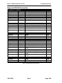
Ithaca Control Codes and Commands .......................................................................... 75
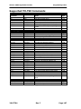
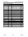
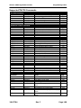
PcOS Printer Control Codes.................................................................................. 75
Quick PcOS Reference Chart ................................................................................ 76
Low Level Paper Motion Control............................................................................ 82
Horizontal Motion Control ...................................................................................... 83
Vertical Motion Control .......................................................................................... 85
Feed to Black Dot .................................................................................................. 91
Character Pitch ..................................................................................................... 93
Character Font ...................................................................................................... 96
Character Sets and Code Pages ........................................................................... 98
Double-Byte and Multi-Byte Code Page Description Files ................................... 100
Code page selection............................................................................................ 100
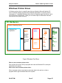
Page Mode .......................................................................................................... 113
Graphic Mode...................................................................................................... 123
Graphics Compression ........................................................................................ 129
User Store (Graphic Save) .................................................................................. 129
User Macros ........................................................................................................ 137
Bar Codes ........................................................................................................... 139
Electronic Journal................................................................................................ 149
Miscellaneous Control ......................................................................................... 161
Remote Power Control ........................................................................................ 169
Documented Extended Control commands ......................................................... 170
Printer Status ...................................................................................................... 171
Inquire Commands .............................................................................................. 172
ESC/POSTM Codes ..................................................................................................... 181
Differences between Epson TM T90 and iTherm® 280 ........................................ 181
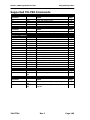
Supported TM-T88 Commands ................................................................................... 183
Undocumented TM-T88 Commands ........................................................................... 186
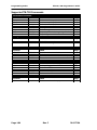
Supported TM-T90 Commands ................................................................................... 187
TM-T88 / TM-T90 and ESC/POSTM Command Descriptions ....................................... 191
Print and Feed Commands ......................................................................................... 191
Line Spacing Commands ............................................................................................ 193
Page 6
Rev C
28-07764
Character Commands ................................................................................................. 193
Panel Button Commands ............................................................................................ 202
Paper Sensor Commands ........................................................................................... 203
Print Position Commands............................................................................................ 205
Bit-Image Commands ................................................................................................. 209
Status Commands ...................................................................................................... 210
Printing Paper Command ............................................................................................ 216
Page Mode ................................................................................................................. 217
Bar Code Commands.................................................................................................. 220
Mechanism Control Commands .................................................................................. 223
Miscellaneous Commands .......................................................................................... 224
Macro Function Commands ........................................................................................ 230
User-defined Images and Graphics Commands .......................................................... 231
Ithaca® Specific iTherm® 280 Commands ................................................................... 236
Panel Button Commands..................................................................................... 236
Paper Out/Low Sensor Commands ..................................................................... 236
iTherm® Citizen Emulation .......................................................................................... 238
iTherm® Star Emulation ............................................................................................... 238
iTherm® Axiohm Emulation ......................................................................................... 238
®
iTherm 280 Color Graphics ......................... 239
Printing Graphics ........................................................................................................ 241
Character Graphics ............................................................................................. 241
APA Graphics...................................................................................................... 244
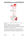
iTherm® 280 Universal Color Graphics ........................................................................ 247
Print File Graphics ............................................................................................... 248
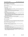
Store Graphics in the printer: ............................................................................... 249
How universal graphics is done ........................................................................... 250
How to use IPCL commands in text strings ......................................................... 250
Cautions .............................................................................................................. 251
Universal Color Command Descriptions .............................................................. 252
iTherm® 280 Coupon-Cut-Logo Feature ...................................................................... 254
Unicode and Fonts ....................................... 255
Unicode and Fonts ....................................... 257
Fonts........................................................................................................................... 257
Character Generation .......................................................................................... 257
Character Definition............................................................................................. 258
Internal Fonts ...................................................................................................... 260
Character Cache ................................................................................................. 260
Custom Fonts ...................................................................................................... 261
Stacked or Linked fonts ....................................................................................... 261
Font Storage ....................................................................................................... 261
Unicode....................................................................................................................... 262
Unicode Encoding ............................................................................................... 262
Bitmap Fonts ....................................................................................................... 265
File system and the POR.INI file ................................................................................. 268
Font Size and Spacing ................................................................................................ 273
Font Size and Spacing command interactions ..................................................... 274
Legacy Printer Features that Have Changed .............................................................. 280
Dynamic code page definition.............................................................................. 280
28-07764
Rev C
Page 7
File System .................................................. 281
File System Interface .................................................................................................. 283
File System commands ....................................................................................... 283
®
iTherm 280 Extended Printer Control ......... 289
Communications .......................................... 297
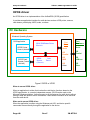
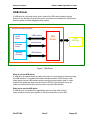
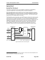
Protocol and Print Buffers ........................................................................................... 299
USB ............................................................................................................................ 302
USB Support ....................................................................................................... 302
TCP/IP ........................................................................................................................ 303
Print Server Features Standard Ethernet Connection .......................................... 303
Supported Protocols ............................................................................................ 303
User Interface/Configuration ................................................................................ 303
Other ................................................................................................................... 303
Parallel Port ................................................................................................................ 304
Parallel Port Protocol........................................................................................... 304
Printer Buffer Size ............................................................................................... 305
Parallel Port Inquire and IEEE 1284 .................................................................... 305
Parallel Port Plug and Play .................................................................................. 307
Serial Port ................................................................................................................... 309
Serial Port Protocol ............................................................................................. 309
Print Buffer Flow.................................................................................................. 311
Printer Buffer Size ............................................................................................... 313
Serial Mode Plug and Play .................................................................................. 313
Using DSR .......................................................................................................... 313
Serial Device Identification .................................................................................. 314
Serial Port Inquire................................................................................................ 315
Display Pass Through ................................................................................................. 316
Remote Power Control ................................................................................................ 316
Remote Printer Reset.................................................................................................. 317
Reset in Serial Mode ........................................................................................... 317
Reset in Parallel Mode ........................................................................................ 317
Miscellaneous Communication Features ..................................................................... 318
Power-cycle Recovery......................................................................................... 318
Data Pass-through .............................................................................................. 318
Multi-drop Configuration ...................................................................................... 318
Off-line Active ...................................................................................................... 319
Recovery from Mechanical Errors ............................................................................... 320
Programmer’s Notes ................................................................................................... 321
Appendix
Appendix
Appendix
Appendix
Appendix
Appendix
Appendix
Page 8
A: Internal Code Pages................. 323
B - ASCII Code Table .................... 324
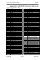
C: Unicode Character Addresses ... 325
D: WGL4.0 Character Addresses ... 327
E: GB18030 Character Addresses . 331
F Windows 1252 Latin 1 ............... 338
G: Ordering Supplies .................... 341
Rev C
28-07764
Index ........................................................... 343
Figures
Figure 1 Receipt Printing, Tear off Position .................................................................. 28
Figure 2 Cash Drawer Pin Definitions ........................................................................... 33
Figure 3 Cash Drawer Selection.................................................................................... 40
Figure 4 3-pin mini DIN plug.......................................................................................... 42
Figure 5 Windows Print Driver....................................................................................... 47
Figure 6 OPOS or UPOS .............................................................................................. 48
Figure 7 USB Driver ...................................................................................................... 49
Figure 8 Ethernet Virtual Serial Driver ........................................................................... 50
Figure 9 POSPrinter OCX ............................................................................................. 51
Figure 10 Page Mode Entry Orientations .................................................................... 114
Figure 11 Page mode set printable area ..................................................................... 117
Figure 12 Default Page mode printed area.................................................................. 118
Figure 13 Defined Page mode printed area................................................................. 119
Figure 14 Code 39 full 128 character encoding ........................................................... 141
Figure 15 Expanded Function coding .......................................................................... 143
Figure 16 Code 128 encoding values .......................................................................... 144
Figure 17 Example of Character Graphics .................................................................. 241
Figure 18 Example Commands for a Sample Receipt ................................................. 242
Figure 19 Sample Receipt........................................................................................... 243
Figure 20 Receipt with graphics .................................................................................. 247
Figure 21 Typical POS System ................................................................................... 299
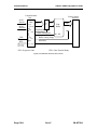
Figure 22 Host to Printer Link...................................................................................... 300
Figure 23 Printer Communications Buffer Flow ........................................................... 301
Figure 24 Parallel-port Data Timing............................................................................. 304
Figure 25 Parallel Port ACK Timing Options ............................................................... 305
Figure 26 Serial Port Flow Control Using DTR ............................................................ 309
Figure 27 XON/XOFF Serial Port Flow Control ........................................................... 310
Tables
Table 1 Standard Power Input Requirements................................................................ 26
Table 2 Power Input Requirements with the 24-volt DC Power ..................................... 26
Table 3: Paper Grades-Monochrome ............................................................................ 27
Table 4 Parallel Interface Pin-outs ................................................................................ 30
Table 5 Serial Interface Pin-outs ................................................................................... 31
Table 6 Cash Drawer Pin Assignment........................................................................... 34
Table 7 Serial interface pin out...................................................................................... 42
Table 8 Parallel interface pin out ................................................................................... 42
Table 9 Error Blink Codes ............................................................................................. 57
Table 10 Character Pitch .............................................................................................. 94
Table 11 Inter-character Spacing .................................................................................. 95
Table 12 Language Table ID’s .................................................................................... 101
Table 13 Euro Character Substitution Matrix ............................................................... 103
28-07764
Rev C
Page 9
Table 14 Paper Sensor Commands ............................................................................ 165
Table 15 Paper Sensor Commands ............................................................................ 166
Table 16 Supported TM-T90 Commands .................................................................... 185
Table 17 Undocumented TM-T90 Commands............................................................. 186
Table 18 Supported EPOS Commands....................................................................... 187
Table 19 Select Character Font Table ......................................................................... 194
Table 20 International Character Sets ......................................................................... 195
Table 21 Character Code Pages ................................................................................. 197
Table 22 Character Code Table .................................................................................. 198
Table 23 Print Modes .................................................................................................. 199
Table 24 Rotation Modes ............................................................................................ 200
Table 25 Paper Sensor Commands ............................................................................ 203
Table 26 Paper Sensor Commands ............................................................................ 204
Table 27 Print Density Selection ................................................................................. 209
Table 28 Automatic Status Back (ASB) Values for <n> ............................................... 210
Table 29 Automatic Status Back (ASB) First Byte (Printer Information)....................... 211
Table 30 Automatic Status Back (ASB) Second Byte (Error Information) .................... 211
Table 31 Automatic Status Back (ASB) Third Byte (Paper Sensor Information) .......... 212
Table 32 Automatic Status Back (ASB) Fourth Byte (Paper Sensor Information) ........ 212
Table 33 Paper Sensor Status (<n> = 1, 49) ............................................................... 212
Table 34 Drawer Kick-out Connector Status (<n> = 2, 50) .......................................... 213
Table 35 Values for the Status Function, <n>.............................................................. 213
Table 36 Printer Status (<n> = 1) ................................................................................ 213
Table 37 Off line Status (<n> = 2) ............................................................................... 214
Table 38 Error Status (<n> = 3)................................................................................... 214
Table 39 Paper Roll Sensor Status (<n> = 4) .............................................................. 214
Table 40 Peripheral Status (<n> = 0, 48) .................................................................... 215
Table 41 Paper Status ................................................................................................ 215
Table 42 Bar Code System Based on <m> ................................................................. 221
Table 43 Printing Position of HRI Characters .............................................................. 222
Table 44 Font for Human Readable Interpretation (HRI) Characters ........................... 222
Table 45 Horizontal size of the bar code ..................................................................... 222
Table 46 Printer ID ...................................................................................................... 224
Table 47 Type ID (<n> = 2 or 50) ................................................................................ 224
Table 48 Peripheral Device Bit Definitions .................................................................. 226
Table 49 Macro Control Bit Definitions ........................................................................ 230
Table 50 User-defined Bit-image Resolutions ............................................................. 235
Table 51 Character Pitch ............................................................................................ 279
Table 52 Parallel-port Timing ...................................................................................... 305
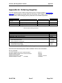
Table 53 Paper Ordering Information .......................................................................... 341
Table 54 Cables Ordering Information ........................................................................ 341
Page 10
Rev C
28-07764
chapter
1
Introducing your iTherm® 280 Printer
28-07764
Rev C
Page 11
This page intentionally left blank
Page 12
Rev C
28-07764
iTherm® 280 Programmer’s Guide
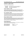
About Your iTherm® 280 Printer
About your iTherm® 280 Printer
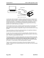
The Ithaca iTherm® 280 printer represents the very latest technology for use for thermal
receipt printing for point-of-sale and retail environments. It builds upon the architecture of
Ithaca’s proven thermal printers, together with a host of features specifically designed to
improve the performance of your receipt-printing applications, including:
•
•
•
•
•
•
•
•
•
Crisp, clear receipt printing in either one or two colors
Fast 8 inches per second print speed
Rugged spill-resistant cover
Large 4-inch paper roll capacity with drop-in loading
Protected internal power supply
Ethernet and USB interfaces
Wireless option for reduced cable clutter
Application-controllable buzzer
Configurable cash drawer functionality
The iTherm® 280 also offers a wide range of programmable features, including color and
font control, APA graphics support, bar codes, and support for over 60 language
character sets. These features let you quickly and easily integrate more layout and
printing options than ever – while giving you the reliability, durability and uptime you
have come to expect from Ithaca printers.
28-07764
Rev C
Page 13
About Your iTherm® 280 Printer
iTherm® 280 Programmer’s Guide
Who Should Read This Guide?
This document provides information and programming specifications for operators who
will integrate the iTherm® 280 printer into their kitchen operations.
What Is Included in This Guide?
This Programmer’s Guide includes information on the features and programming
interface of the iTherm® 280 printer. It provides the following information to support your
programming and implementation efforts:
•
•
•
Warranty and technical support information.
Specifications and functionality description.
Programming information, including documentation of low-level and high-level
command interfaces, as well as sample scripts to guide your own implementation
efforts.
We want you to have a trouble-free implementation with your Ithaca printer. For any
issues not covered in this guide, quality technical support is available on-line at
www.transact-tech.com, or by telephone at (607) 257-8901 or (877) 7ithaca. Consult
the following pages for more details about our support services.
Warranty Options
All iTherm® 280 printers come with a standard 24-month standard warranty covering
both parts and labor that starts upon shipment from the factory. An optional extended
warranty, covering both parts and labor for an additional 12 months, may be purchased
separately. For more information concerning the warranty options, please contact the
Sales Department at TransAct’s Ithaca facility. You are responsible for insuring any
product returned for service, and you assume the risk of loss during shipment to Ithaca.
C.O.D. packages are not accepted and warranty repairs are subject to the terms and
conditions as stated on the Ithaca warranty policy.
Page 14
Rev C
28-07764
iTherm® 280 Programmer’s Guide
About Your iTherm® 280 Printer
Technical and Sales support
Your Ithaca printer is backed by the resources of TransAct Technologies, a global
technology firm with dedicated technical support and sales assistance. Here is how we
can help you:
On-line Technical Support
Our web site at www.transact-tech.com is your on-line portal to obtaining technical
assistance with your Ithaca printer. Click on Ithaca link and then the Technical Support
link to find documentation for your iTherm® 280 printer, including a current copy of this
Programmer’s Guide featuring:
o
o
o
o
Command codes and descriptions.
Character fonts.
Printer features.
Communication specifics.
Other utilities available include a font utility, a color converter and a terminal application
for communicating with your printer, as well as the following drivers and utilities:
Windows 95/98/Me Print Driver with Documentation
Windows NT 4.0 2K and XP Print Driver with Documentation
OPOS Drivers with Documentation
Master Character Set Definitions
Part No.
Part No.
Part No.
Part No.
100-9167
100-9170
100-9732
100-9785
Our on-line support site also includes a convenient e-mail assistance request form,
where you can submit support requests 24 hours a day, and receive a return contact
from a TransAct support technician during regular business hours.
Telephone Technical Support
Live telephone support is available Monday through Friday from 8 AM to 5 PM Eastern
US time, excluding holidays. We can provide general information about programming for
your iTherm® 280 printer, technical support, documentation, or assistance in sending a
printer for service. To obtain telephone support, call TransAct's Ithaca Facility at (607)
257-8901 and ask for Technical Support. To help us serve you faster, please have the
following information ready when you call:
•
•
•
•
•
The Model Number and Serial Number of the printer.
A list of any other peripheral devices attached to the same port as the printer.
What application software, operating system, and network (if any) you are using.
What happened and what you were doing when the problem occurred.
How you tried to solve the problem.
28-07764
Rev C
Page 15
About Your iTherm® 280 Printer
iTherm® 280 Programmer’s Guide
Return Materials Authorization and Return Policies
If the technical support person determines that the printer should be serviced at our
facility, and you want to return the printer for repair, we will issue you the Returned
Materials Authorization (RMA) number that is required before returning the printer.
Repairs are warranted for 90 days from the date of repair or for the balance of the
original warranty period, whichever is greater. Please prepare the printer being returned
for repair as follows:
•
•
•
•
Pack the printer to be returned in the original packing material.
Packing material may be purchased from TransAct's Ithaca Facility.
Do not return any accessories unless asked to do so by a support technician.
Write the RMA number clearly on the outside of the box.
Service Programs
TransAct Technologies Incorporated has a full service organization to meet your printer
service and repair requirements. If your printer needs service, please contact your
service provider first. If any problems still persist, you can directly contact the Ithaca
facility’s Technical Support Department at (607) 257-8901 or (877) 7ithaca for a return
authorization. International customers should contact your distributor for services.
TransAct offers the following service programs to meet your needs.
•
•
•
•
Extended Warranty.
Depot Repair.
Maintenance Contract.
Internet Support.
Sales Support
To order supplies, receive information about other Ithaca products, or obtain information
about your warranty, contact our Sales Department at the contact telephone or fax
numbers listed below. To receive information on International distribution, visit our web
site at www.transact-tech.com.
Contact Information
TransAct Technologies Incorporated
Ithaca Facility
20 Bomax Drive
Ithaca, NY 14850 USA
Telephone
Main fax
Page 16
(877) 7ithaca or (607) 257-8901
(607) 257-8922
Rev C
28-07764
iTherm® 280 Programmer’s Guide
Sales fax
Technical Support fax
Web site
28-07764
About Your iTherm® 280 Printer
(607) 257-3868
(607) 257-3911
www.transact-tech.com
Rev C
Page 17
chapter
2
iTherm® 280 Specifications and Requirements
28-07764
Rev C
Page 19
This page intentionally left blank
Page 20
Rev C
28-07764
iTherm® 280 Programmer’s Guide
Specifications and Requirements
iTherm® 280 Specifications and Requirements
iTherm® 280 Thermal Printer Models
•
•
•
iTherm® 280-P: parallel interface printer
iTherm® 280-S: serial interface printer
iTherm® 280-USB: USB interface printer
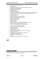
Standard Features
The following features are common to the entire family of thermal printers:
•
•
•
•
•
•
•
•
•
•
•
Print Speed for text is 8 inches per second (200 mm/sec) (monochrome)
8.0 inches per second paper feed speed
3.15 inch (80 mm.) print zone
44/57 characters per line
Built-in self-ranging External Power supply
Clam-shell paper loading
Single RJ11 cash drawer driver with status (Single RJ12)
Parallel (25 or 36 pin), serial (9 or 25 pin) RS232C, and USB interface
Configurable receiver buffer
Self diagnostics
Set up and configuration utility program
28-07764
Rev C
Page 21
iTherm® 280 Programmer’s Guide
Specifications and Requirements
•
•
•
•
•
•
•
•
•
•
•
•
•
•
•
•
•
•
•
•
•
•
•
•
•
•
•
•
•
•
•
CPI selections from 8 to 30 CPI1
Paper Out sensor
Multiple printer emulations: Ithaca PcOS and Epson Extended,
Maximum 8K buffer (adjustable)
2 Megabytes Flash Memory
2 Megabytes RAM
APA and Epson graphics
Bar Codes: Code 39, Code 93, Code 128, Interleaved 2 of 5, UPC-A, UPCE, EAN-8, EAN-13, EAN-14, PDF417 stacked symbology and Codabar
WGL4.0 Character set.
Metal receipt tear off
8 dots/mm. thermal print head resolution
ON/OFF button located on front of printer
Cable routing strain relief
Power/Error/Paper LEDs
Paper feed button
Cover open button
Settable cash drawer configurations (Ithaca, Epson, or Star)
Spill proof design- vertical main PCB mounting
58 mm. or 80 mm. paper width – factory-settable
4.0 inch (101 mm.) Paper roll diameter
Portrait/landscape printing under Windows
Page mode printing
Cover Open sensor
Electronic journal capability
Internal counters for hours on, cuts, print lines and errors
100 km print head life
60 million print line printer MCBF (excluding knife)
Strong break-away paper cover
1,000,000 cuts cutter life (partial cut)
Buzzer
2 color printing (4 inches per second print speed)
1
Character spacing is adjustable from 1 to 30 CPI. Typical values will be between 8 and 20 CPI
depending on the font selected. Values of 13.3, 14.86, or 17.3 are typical for each resident font.
2
CPI’s greater than 16 will not be supported in NLQ fonts
Page 22
Rev C
28-07764
iTherm® 280 Programmer’s Guide
Specifications and Requirements
Optional Features
The following options are available on some of the models:
•
•
•
•
•
•
Vertical Wall Mount Kit
Adjustable paper low
OCR TrueType font
Chinese GB18030 Font.
Custom interfaces and emulations
DC powered version through Hosiden type connector
28-07764
Rev C
Page 23
iTherm® 280 Programmer’s Guide
Specifications and Requirements
General Specifications
Printing Specifications
Printing method:
Vertical/Horizontal dot pitch:
Resolution:
Line feed pitch:
Print zone (maximum)
Print speed (monochrome):
Print Speed (two color):
Number of print elements:
Thermal Sensitive Line Dot System
0.125 mm.
8 dots per mm (203 DPI)
3.2 mm. (.125 inches)
80 mm (3.15 inch)
8 inches per second
4 inches per second
640 dots in-line
Physical Characteristics
Dimensions
Page 24
Rev C
28-07764
iTherm® 280 Programmer’s Guide
Specifications and Requirements
Max Dimensions
Dimensions in
inches
W
6.25
D
8.50
H
5.87
Weight
Approximate weight:
Shipping weight:
28-07764
4.6 lb.
6.0 lb.
Rev C
Page 25
iTherm® 280 Programmer’s Guide
Specifications and Requirements
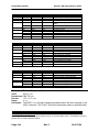
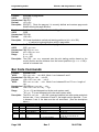
Electrical Characteristics
Internal AC Powered
The iTherm® 280 Printer is designed to be AC self-powered in domestic and
international markets. The printer is equipped with a universal input power supply that is
designed to operate worldwide without modification.
Supply
Voltage
Rating
(VAC)
100-240
Supply
Voltage
Range
(VAC)
90-264
Frequency
(Hz)
Rated Power
(watts)
47 – 63
45
Idle Current
(amps)
.1A @ 120VAC
.05 A @ 240VAC
Table 1 Standard Power Input Requirements
Printing Current
(amps)
1.4 A @ 120VAC
.7 A @ 240VAC
External Powered DC
Optionally, the iTherm® 280 Printer can be operated with 24-volt DC power supplied
from a host terminal or external supply. Connection to this printer version is made via a
three-pin Hosiden type connector.
Supply
Voltage
Rating
(VDC)
24
-5+10%
Supply
Voltage
Range
(VDC)
22.8 –
26.42
Frequency (Hz)
Idle
Current
(amps)
Current (amps)
DC
0.125 A
2.0 A (Cash Drawer Fire)
3.5 A (Printing maximum for < 1 minute)
4.8 A Peak (< 167 msec.)
Table 2 Power Input Requirements with the 24-volt DC Power
The iTherm® 280 can be configured to operate with various power supplies. If a DC
power supply with less capability is used, the printer must be configured for reduced
power and the printer will print slower.
Thermal Print Head
Thermal Print Head Overview:
Number of heat elements:
Heat element pitch:
Print width:
Pulse Life:
Abrasion Life:
Vertical dot pitch
Operating Temperature
Humidity:
640
0.125 mm (8 dots/mm.)
80 mm. +/- 0.2 mm.
100 million pulses
100 km.
0.264 mm (0.0104 inch) or 96 DPI
5-45 degrees C
10-90 % RH (non-condensing)
Operation Precautions:
• Do not print without paper.
• Clean the head with ethyl-alcohol after power is removed from the printer. This will
remove foreign particles or paper dust which may degrade print quality.
• Be sure to set the paper width in the printer’s configuration to agree with the paper
being used (58 or 80 mm width).
2
For DC powered printers, the cash drawer is supplied directly from the DC input supply. The
cash drawer requirements may affect the allowable range of voltages.
Page 26
Rev C
28-07764
iTherm® 280 Programmer’s Guide
•
Specifications and Requirements
Once narrow paper has been used, some part of the print head always contacts the
platen. If 80 mm. paper is used after setting up and running 58 mm. paper, the head
or the cutter blade may be worn out. Never change the paper width from narrow to
wide (58 to 80 mm.) once you set the paper width to narrow (58 mm.).
Media Specifications
Receipt Paper
Paper feed method
Paper feed pitch
Paper width
Roll diameter
Paper thickness
Roll paper core
Roll footage
Friction feed
Default - 1/8 inch
80 mm: 79.5 +/- 0.5 mm. (3.13 +/- 0.02 inches)
58 mm: 57.5 +/- 0.5 (2.26 +/- 0.02 inches)
101.6 mm. (4.0 inches) Max.
0.06 to 0.09 mm. (.00225 to .0035 inches)
Inside diameter .445 to .635 inches
Outside diameter .730 to .860 inches
400 feet (min.)
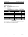
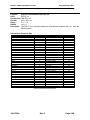
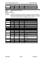
Thermal Paper Grades (Monochrome)
Paper
Manufacturer
Basis Weight
Caliper
Image color
Brightness
Activation Temp.
Smoothness (bekk)
Kanzaki P-300
Kanzaki P-310
Appleton Alpha 400-2.3
14.1 lbs.
14.2 lbs.
.00225 mils
.00226 mils
black
Black
85%
85%
Initial: 74+/-5°C
Initial:73 +/-5°C
Effective: 87 +/- 5°C
Effective: 83 +/- 5°C
Optimum: 100 +/- 5°C
Optimum: 88 +/- 5°C
325 sec. Ave.
325 sec.Ave.
Table 3: Paper Grades-Monochrome
14.5 lbs.
.00235 inches
Black
87%
Initial:77.2°C
Optimum: 104.8 +/- 5°C
200 (bekk).
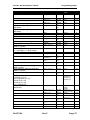
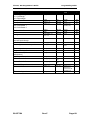
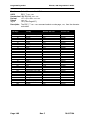
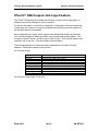
Thermal Paper Grades (color)
Paper
Manufacturer
Kanzaki P-320 RB
Kanzaki P-320 BB
Appleton Dual RB
Appleton Dual BB
Basis Weight
Caliper
Brightness
Image color
Thermal
Response
14.6 lbs.
.00227 mils
87 %
Red/Black:
Initial(Red):80 +/-5°C
Initial(B):98 +/-5°C
Effective(Red): 87 +/- 5°C
Effective(B): 116 +/- 5°C
Optimum(Red):100 +/-5°C
Optimum(B):130 +/-5°C
14.6 lbs.
.00227 mils
87 %
Blue/Black
Initial(Blue):74 +/-5°C
Initial(B):90 +/-5°C
Effective(Blue): 80 +/- 5°C
Effective(B): 120 +/- 5°C
Optimum(Blue):90 +/-5°C
Optimum(B):130 +/-5°C
15.6 lbs.
.00235 mils
89.5 %
Red/Black:
Initial(Red):77.8 +/-5°C
Initial(B):77.8 +/-5°C
Optimum(Red):90.5 +/-5°C
Optimum(B):103.3 +/-5°C
15.6 lbs.
.00235 mils
87.8 %
Blue/Black
Initial(Blue):69.4 +/-5°C
Initial(B):69.4 +/-5°C
Optimum(Blue):82 +/-5°C
Optimum(B):118 +/-5°C
Smoothness
(bekk)
500 sec. ave.
500 sec. ave.
250 sec./min.
250 sec./min.
Table 8: Paper Grades-Color
Paper Usage Precautions:
• The life of the thermal head, when two-color paper is used, is reduced to half of the
life when single-color thermal paper is used.
28-07764
Rev C
Page 27
iTherm® 280 Programmer’s Guide
Specifications and Requirements
•
Use only specified thermal paper. If other paper is used, print quality, head life, and
cutter life may deteriorate.
Paper Out
A receipt paper out sensor is provided as a standard feature. It senses when there is
approximately .5 inches length of paper left on the paper roll.
Paper Low
A receipt paper-low sensor is provided as an optional feature. An operator adjustable
paper-low assembly will be provided to allow the printer to sense when the paper roll
diameter is between .94 to 1.29 inches (approximate). It is adjustable to compensate for
various paper core dimensions.
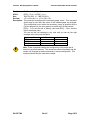
Paper Low Adjustment Settings
UPPER LIMIT: 2 turns (counter clockwise)
1 turn (counter clockwise)
FACTORY SETTING
1 turn (clockwise)
LOW LIMIT: 2 turns (clockwise)
Approximate Paper Remaining
(in feet)
29’
23’
18'
13'
8.5‘
Paper Roll Diameter
1.29"
1.203"
1.115"
1.028"
.940“
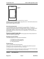
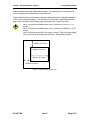
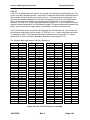
Notes:
• These measurements are approximate. Paper roll used for testing had paper roll
core outside diameter of .750 inches, and inside diameter is .625 inches. Results will
vary depending on core O.D./I.D. dimensions.
• Paper roll core should meet or exceed paper width.
• Results based on thermal paper .0025 inches thick.
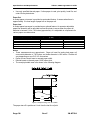
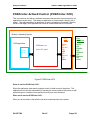
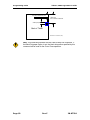
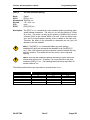
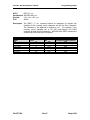
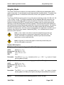
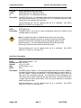
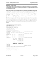
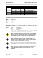
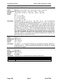
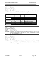
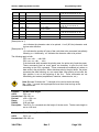
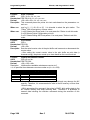
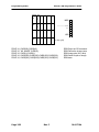
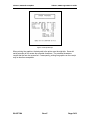
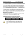
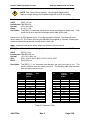
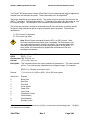
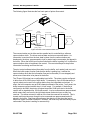
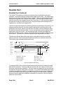
• The receipt printable area is as shown in the following diagram.
1.00”
2.83
0.15
3.15
Figure 1 Receipt Printing, Tear off Position
The paper tear off is positioned 1 inch from the last line of print
Page 28
Rev C
28-07764
iTherm® 280 Programmer’s Guide
Specifications and Requirements
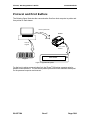
Receipt Printing, Auto Cutter Position
A receipt auto-cutter is a standard feature with all iTherm™ 280 Printers.
Cutter type
Rotary
Media width
3.13 +/- .02 inches (79.5 +/- .5 mm)
Media thickness range
0.0025 to 0.0035 inch
Cut to line of print
0.70 inch
Cutter life
1,000,000 cuts
Partial Cut tab:
.125 inches +/- .0625 inches (right edge of receipt)
Cut time:
Less than 350 milliseconds
Buzzer
A buzzer is provided as a standard feature. It is triggered upon command from the host
terminal to make a sound loud enough to be heard under noisy conditions. It will produce
a sound pressure level of at least 90 dBA, 1 foot from the front of the printer.
Cover Interlock
A paper cover interlock switch is provided as a standard feature. When the paper cover
is open, the printer is off-line, and will not print.
Display Pass Through
The display pass through feature allows a pole display to be interconnected with the
printer. The printer is connected to a host system with a special serial cable. The host
sends serial data to the printer and the printer sends serial data to the pole display. The
printer does not provide power to the display. During normal printer operation, no data is
passed to the display. In pass through mode, all received data is passed on to the
display.
28-07764
Rev C
Page 29
iTherm® 280 Programmer’s Guide
Specifications and Requirements
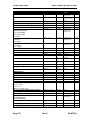
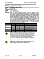
Communications Interface
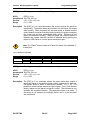
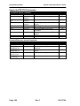
Parallel Interface
Your printer features two parallel interfaces:
•
•
An IEEE 1284-A 25-pin, D-shell connector, with pin-outs that interface to a
standard IBM PC parallel printer interface with a one-to-one cable.
An IEEE 1284-B, which is a standard Centronics 36-pin connector.
Both interface cards provide a dual cash drawer interface. The following table lists
interface signals and corresponding pins.
25-pin Connector
Pin 1
Pins 2-9
Pin 10
Pin 11
Pin 12
Pin 13
Pin 14
Pin 15
Pin 16
Pin 17
Pins 18-25
36-pin Connector Signal
Description
Pin 1
STROBE
Clock data to printer
Pins 2-9
D0 - D7
Data
Pin 10
ACK\
Printer accepted data
Pin 11
BUSY
Printer busy
Pin 12
PE
Paper Out/Status
Pin 13
SLCT
Printer selected
Pin 14
AUTOFD
Autofeed paper
Pin 32
FAULT\
Printer error
Pin 31
INIT\
Initialize printer
Pin 36
SLIN
Select printer
Pin 17
FG
Frame ground
Pin 18
+5V
Peripheral logic high
Pins 16, 19-30
GND
Ground
Table 4 Parallel Interface Pin-outs
Direction
Host to Printer
Host to Printer
Printer to Host
Printer to Host
Printer to Host
Printer to Host
Host to Printer
Printer to Host
Host to Printer
Host to Printer
Printer to Host
Printer to Host
Signal Levels
Voltage levels
Logic levels
Logic one
Driver
Receiver
Logic zero
Driver
Receiver
Current requirements
Logic one
Logic zero
Line termination
Data and control
Strobe
Page 30
0 V and +5 V (nominal)
+2.4 V to +5 V
+2.0 V to +5 V
0 V to +0.4 V
0 V to +0.8 V
Source
Sink 16 ma
0.25 ma at +2.4 V
3.3k ohm to +5 V
1.2k ohm to +5 V
Rev C
28-07764
iTherm® 280 Programmer’s Guide
Specifications and Requirements
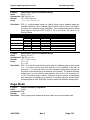
RS-232 Serial Interface
Serial Port Features
The serial port features are as follows:
Baud Rates
Bit Patterns
Flow Control
9-pin
Pin 1
Pin 2
Pin 3
Pin 4
Pin 5
Pin 6
Pin 7
Pin 8
Pin 9
300, 600, 1200, 2400, 4800, 9600, 19.2K, 38.4K, and 57.6K
8-bit no parity; 8-bit odd; 8-bit even; 7-bit no parity; 7-bit odd; 7-bit even
DTR and XON/XOFF
25-pin
Signal
Pin 8
Pin 3
RX
Pin 2
TX
Pin 20
DTR
Pin 7
GND
Pin 6
DSR
Pin 4
RTS
Pin 5
CTS
Pin 11
Table 5 Serial Interface Pin-outs
Description
Not Connected
Receive Data
Transmit Data
Data Terminal Ready
Signal Ground
Data Set Ready
Request to Send
Clear to Send
Not Connected
Signal Voltage and Current levels
The serial interface meets EIA RS232 interface specifications:
Voltage Levels
Mark = Off =
Space = On =
Max
Min
-3 to –15 Volts
+3 to +15 Volts
+-15 Volts
+- 3 Volts
Because both the host and printer are DTE's (Data Terminal Equipment), they use the
same serial port pin-outs. If the cable that is used to connect the host to the printer is a
pin-to-pin inter-connect, it will not work. Therefore, a null modem or turn-around cable
must be used to interconnect the host and the printer.
Display Pass Through
The display pass through feature allows a pole display to be interconnected with the
printer. The printer is connected to a host system with a special serial cable. The host
sends serial data to the printer and the printer sends serial data to the pole display. The
printer does not provide power to the display. During normal printer operation, no data is
passed to the display. In pass through mode, all received data is passed on to the
display.
USB Interface
The USB interface is a Version 1.1 interface that is Version 2.0 compliant. The standard
USB interface card is implemented through a Standard Series "B" Receptacle as defined
in the USB Specification. The printer is self-powered and does not draw power from the
standard type B USB interface cable.
The Standard USB Type B connector has the following pin functions:
Pin Signal
28-07764
Rev C
Page 31
iTherm® 280 Programmer’s Guide
Specifications and Requirements
1 Vbus (+5 V dc) (Not used in the iTherm® 280)
2 Minus data
3 Plus data
4 Ground
Note: The standard USB interface does not have enough power to run the
printer.
Ethernet 10-Base-T adapter
An IP addressable 10-Base-T Ethernet adapter is available for the iTherm® 280 printer.
It provides for web page configuration and supports bi-directional RAW and Telnet
interfaces. All protocols are implemented to the extent necessary to support printing
from Windows™ platforms; specific protocols supported include the following:
•
•
•
•
•
•
•
•
Line Printer Daemon Protocol (LPR) – RFC1179
Simple Network Management Protocol (SNMP) – RFC1157
Printer MIB – RFC1759
Port 9100 (Raw data)
Service Location Protocol (SLP) – RFC2165
The TFTP Protocol (Revision 2) – RFC1350
Telnet COM Port Control Option – RFC2217
Hypertext Transfer Protocol – HTTP/1.1 – RFC2616
Refer to the 100-05072 Wired Ethernet Programmer’s Guide for features and additional
setup information.
Note: The Ethernet adapter supports only the Ithaca Cash Drawer
interface.
802.11b Wireless Interface
An 802.11b wireless interface is available for the iTherm® 280 printer, allowing wireless
operation of the printer within a specified distance of a base unit. Contact TransAct
technical support for more information on this interface.
Page 32
Rev C
28-07764
iTherm® 280 Programmer’s Guide
Specifications and Requirements
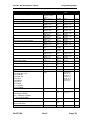
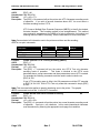
Cash Drawer
Interface Description
The iTherm® 280 Printer supports a single cash drawer with status. The driver in the
printer is capable of supplying 24 V DC at up to 1.5 amps for up to 250 milliseconds. The
iTherm® 280 Printer defines cash drawer closed as switch open. If the drawer is
disconnected, it will be viewed by the printer as closed. Since the printer does not act on
the cash drawer status, the application can interpret cash drawer status any way it
wants.
Driver connector type (standard)
Driver voltage
Driver current
Pulse duration
Drawer status
Single RJ12 connectors with 24V sink drivers
24 volts (Refer to power supply specification).
1 amp maximum with current limit
250 msec. maximum
Open/close drawer status provided to printer
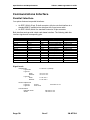
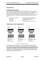
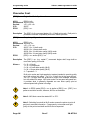
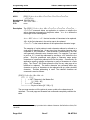
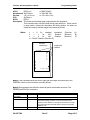
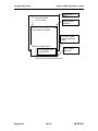
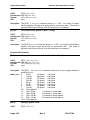
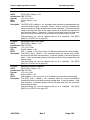
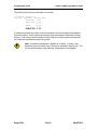
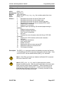
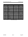
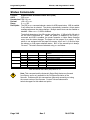
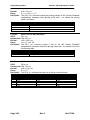
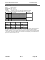
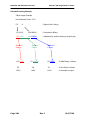
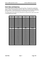
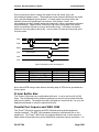
Cash Drawer Pin Assignments
Ithaca
Epson
Star
1 2 3 4 5 6
1 2 3 4 5 6
1 2 3 4 5 6
pin
pin
pin
pin
pin
pin
pin
pin
pin
pin
pin
pin
pin
pin
pin
pin
pin
pin
1
2
3
4
5
6
CD2CD1 Sense
Ground
CD Drive + (+24V)
CD1Not Connected
1
2
3
4
5
6
Not Connected
CD1CD1 Sense
CD Drive + (+24V)
CD2Ground
1
2
3
4
5
6
Not Connected
CD1CD Drive + (+24V)
CD Drive + (+24V)
CD2CD1 Sense
Figure 2 Cash Drawer Pin Definitions
The cash drawer can be configured for one of three configurations; Ithaca, Epson, or
Star. The Main Controller PCB has three (3) six-pin headers, one each configuration.
The cash drawer harness is identical, and is plugged into the appropriate header at time
of factory build. The header position defines the configuration of the cash drawer. This
design allows for changing the cash drawer in the field by a trained technician. Refer to
the markups on the board when determining where the harness should be installed to
work in the three different configurations.
28-07764
Rev C
Page 33
iTherm® 280 Programmer’s Guide
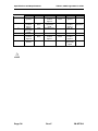
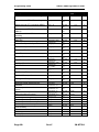
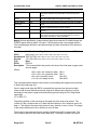
Specifications and Requirements
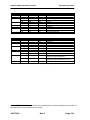
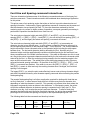
Pin Number
1
2
3
4
5
6
Ithaca
Signal Name
Frame
ground
Drawer kickout drive
signal 1
Drawer
open/close
signal
+24V DC
Drawer kickout drive
signal 2
Signal
Ground
Direction
Output Sink
Drive
Input
Output Sink
Drive
Epson
Signal Name
Drawer kickout drive
signal 2
Drawer
open/close
signal
Signal ground
+24V DC
Drawer kickout drive
signal 1
Frame Ground
Direction
Output Sink
Drive
Input
Output Sink
Drive
Star
Signal Name
Frame
ground
Drawer kickout drive
signal 1
+24V DC
+24V DC
Drawer kickout drive
signal 2
Drawer
Open/Close
signal
Direction
Output
Sink Drive
Output
Input
Table 6 Cash Drawer Pin Assignment
Page 34
Rev C
28-07764
iTherm® 280 Programmer’s Guide
Specifications and Requirements
Vertical Wall Mount Kit Option
A kit is available as an add-on option that allows the iTherm® 280 printer to be vertically
mounted to a wall. It is comprised of a metal mounting bracket that attaches to the base
of the printer with two M6 thread-cutting screws. Additional hardware is required to
mount the bracket to the wall. The hardware should be installed into wall studs to
ensure that the printer mounting meets the following conditions:
•
•
•
The mounting to the wall must withstand 4 times the printer weight in downward and
outward directions.
The kit must include mounting instructions to explain how to meet the load test
The firewall or the outer housing of the printer is maintained between the controller
PCB and the mounting wall.
28-07764
Rev C
Page 35
chapter
3
Setup Procedures
28-07764
Rev C
Page 37
This page intentionally left blank
Page 38
Rev C
28-07764
iTherm® 280 Programmer’s Guide
Setup Procedures
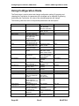
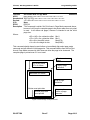
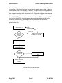
Verifying the Configuration
Before you install an iTherm® 280 Printer into your system, you should verify that the printer is
configured as required by your system. There are four parts to this verification process.
1.
2.
3.
4.
Verify that the communications interface card is the correct one.
Verify that the cash drawer interface is configured correctly.
Verify that the power connection is correct.
Verify that the firmware in the printer is configured correctly.
Verify the Communications Interface Card
There are several basic types of interface cards, and each has variations. Make sure your
printer has the correct interface card.
Parallel Interface
• Centronics 36-pin interface
• 25-pin D shell
Serial Interface
• 9-pin D shell interface
• 25-pin D shell interface
USB Interface
• Standard 4-pin
Ethernet 10-Base-T Adapter
• Standard Ethernet port connector
802.11b Wireless Interface
• Wireless interface pre-installed within printer unit
It is easy to distinguish most of the interface cards other than the 25-pin serial and 25-pin
parallel interface cards. To determine what interface is installed, refer to the configuration
receipt shipped with the printer, or enter configuration mode and look at the verification printout.
If a serial interface card is installed, the printout will refer to the RS-232 serial interface. If the
parallel interface card is installed, the printout will refer to the parallel interface.
Changing Interface Cards
The interface card on the iTherm® 280 Printer can be changed in the field.
In most cases, interface cards are interchangeable without altering the printer firmware.
However, you may have to load new firmware and/or a new boot loader before you change the
interface cards. Check with Technical Support for firmware compatibility between interface
cards before ordering.
Removing the Old Interface Card
1.
2.
3.
4.
5.
6.
Turn over the printer, taking care not to allow the cover to open or the paper to fall.
Disconnect the current communications and cash drawer cables.
If equipped, unsnap the power supply retainer and slide out the power supply.
Disconnect the power supply from the interface card.
Remove the interface retaining screw.
Slide the interface card sideways-towards the power supply pocket-and remove it.
28-07764
Rev C
Page 39
iTherm® 280 Programmer’s Guide
Setup Procedures
Cash Drawer Configuration
Verify the Cash Drawer Interface
The printer is shipped from the factory with a cash drawer interface label on the bottom of the
printer. You should always verify that the cash drawer you are using matches the printer’s cash
drawer interface label. If there is no cash drawer label, you should remove the communications
interface card and verify the setting. See "Configuring the Cash Drawer Interface" on page 40 .
There are many vendors of cash drawers. If you are unsure what the cash drawer interface is,
contact the cash drawer vendor for more information.
If you find that the cash drawer does not match the printer, you may change the printer's cash
drawer interface configuration. If the cash drawer interface no longer matches the label on the
printer, please remove the label.
Install the new interface card
1. Slide the interface card into the printer. Make sure the interface card sits flush with the
printer. The retaining screws should also line up with the mounting holes.
2. Install the retaining screws.
3. Connect the communications interface card and any cash drawer cables.
4. Turn over the printer, and reconnect the power.
Configuring the Cash Drawer Interface
CD interface drawing not yet available.
Figure 3 Cash Drawer Selection
The cash drawer connector may be connected to one of three internal connectors on the
controller board. To access the internal connector, you must first remove the interface adapter.
Removing the interface card
1. Unplug the printer
2. Turn over the printer. Take care not to allow the cover to open or the paper to fall.
3. Disconnect the current communications and cash drawer cables.
4. Remove the interface retaining screw2.
5. Slide the interface card towards the back of the printer and remove it.
Reconfigure the cash drawer
1. Slide the cash drawer socket out of the slot in the frame.
2. Unplug the socket harness from the main circuit board.
3. Plug the harness into the connector for the desired interface.
4. Reinstall the cash drawer socket into the frame.
Re-Install the interface card
1. Slide the interface card into the printer. Make sure the interface card sits flush with the
printer. The retaining screws should also line up with the mounting holes.
2. Install the retaining screws.
3. Connect the communications interface card and any cash drawer cables.
4. Turn over the printer, and reconnect the power.
Page 40
Rev C
28-07764
iTherm® 280 Programmer’s Guide
Setup Procedures
Installing Cables
Three cables are required to be connected to the printer.
1. Power
2. Communications
3. Cash Drawer
Connecting power
The iTherm® 280 Printer is generally supplied with a built-in power supply. As an option, the
printer is available without a power supply.
Internal Supply
The internal supply connects to an outside power source with a standard two wire power cord.
28-07764
Rev C
Page 41
iTherm® 280 Programmer’s Guide
Setup Procedures
External Supply
If an external supply is used a 3 pin mini DIN plug is provided for the external 24 Volt supply.
Earth Ground
+24 Vo lt Supply
Ground (+24 V dc)
Figure 4 3-pin mini DIN plug
Connecting Communications Cables
The iTherm® 280 has a number of different communications interfaces.
Serial
The serial interface connector is either a 9-pin or 25-pin mail D shell interface. The pin-out is
shown below
9-pin
Pin 2
Pin 3
Pin 4
Pin 5
Pin 6
Pin 7
Pin 8
25-pin
Pin 3
Pin 2
Pin 20
Pin 7
Pin 6
Pin 4
Pin 5
Signal
Description
RX
Receive Data
TX
Transmit Data
DTR
Data Terminal Ready
GND
Signal Ground
DSR
Data Set Ready
RTS
Request to Send
CTS
Clear to Send
Table 7 Serial interface pin out
Parallel
The parallel interface connection is very similar to the serial interface connection. It can be a
36-pin Centronics (IEEE 1284-B) or a 25-Pin female D-Shell (IEEE 1284-A) connector. The pinout of both connectors are shown below
25-pin
Connector
Pin 1
Pins 2-9
Pin 10
Pin 11
Pin 12
Pin 13
Pin 14
Pin 15
Pin 16
Pin 17
Pins 18-25
Page 42
36-pin
Connector
Pin 1
Pins 2-9
Pin 10
Pin 11
Pin 12
Pin 13
Pin 14
Pin 32
Pin 31
Pin 36
Pin 17
Pin 18
Pins 16, 19-30
Signal
Description
STROBE
Clock data to printer
D0 - D7
Data
ACK\
Printer accepted data
BUSY
Printer busy
PE
Paper Out/Status
SLCT
Printer selected
AUTOFD
Auto-feed paper
FAULT\
Printer error
INIT\
Initialize printer
SLIN
Select printer
FG
Frame ground
+5V
Peripheral logic high
GND
Ground
Table 8 Parallel interface pin out
Rev C
Direction
Host to Printer
Host to Printer
Printer to Host
Printer to Host
Printer to Host
Printer to Host
Host to Printer
Printer to Host
Host to Printer
Host to Printer
Printer to Host
Printer to Host
28-07764
iTherm® 280 Programmer’s Guide
Setup Procedures
USB
The USB connector can be one of two types: a standard Type B connector, as in commonly
used in the PC industry, or a POS Powered USB connector. In the case of the powered USB
connector, there are a number of different versions. Make sure you are using a 24 volt DC
version, and the 24 volt supply meets the requirements of the iTherm® 280 printer and any cash
drawer that is connected to the printer.
A powered USB interface is a special order option. There are several standards for the power
interface. Make sure that you inform TransAct is aware of what interface you require, and that
that interface connector is supported by the iTherm® 280.
Verify the Firmware Configuration
An example receipt is Included in the box your printer shipped in that will show how the printer
was configured before it shipped from our Ithaca facility. Compare this information to your
system requirements. Pay attention to the emulation and the communications link. If they are
wrong, the printer may appear inoperative. If the configuration is not correct, refer to the section
on changing the iTherm® 280 configuration. If there are a number of printers to be installed and
you want the identical configuration in each, you can use the universal configuration program to
record the configuration on one printer, and replicate it over a group. The configuration program
is available from Transact technical support.
Installing Paper
It is easy to install paper in the iTherm® 280.
1. Open the paper cover by grasping the green cover release between your thumb and
forefinger, and squeeze the release. This will pop the cover up.
2. Open the cover and install a roll of paper with the paper coming off of the bottom of the
roll.
3. Lay the paper tail over the front of the printer and center it over the paper path.
4. Close the cover. When the cover is closed, the printer will feed several inches of paper
to make sure the paper is aligned in the printer. If equipped with a cutter, the printer will
automatically cut the paper tail and the printer is now ready to print. If the printer is not
equipped with a cutter, the operator should remove the paper tail.
28-07764
Rev C
Page 43
iTherm® 280 Programmer’s Guide
Setup Procedures
Printer Drivers and Printer Controls
Definitions for terms you will see in this guide:
OS – The Operating System, which is the operating software underlying a computer
system. Examples of OS’s include Microsoft Windows® (9x/Me/2000/XP), Linux, Unix,
and OS2.
Application - A software program that a person uses to perform a function, such as a
point of sale (POS) application. Also referred to as a program.
Driver - Software that makes hardware do something (something useful, we hope!). A
driver translates (or converts) a software command to a command that specific hardware
can understand. Types of drivers include printer drivers, port drivers, OPOS drivers, and
USB drivers.
OCX/ActiveX - a software component that utilizes Microsoft’s OLE (Object linking and
embedding).
API - Application Programming Interface, or the language used to develop applications
for devices such as printers. In the generic sense, the term “the API” refers to the
Windows Operating System API. Types of APIs include Windows API, Visual Basic API,
Delphi API, and MFC API.
Page 44
Rev C
28-07764
iTherm® 280 Programmer’s Guide
Setup Procedures
Getting Started – Questions to Ask
Most driver software for TransAct Technologies printers fall into one of three main
categories:
•
They support or emulate a specific type of communications port – for example, a
USB port driver, or a driver to emulate a serial port via an Ethernet interface.
•
They support the industry standard OPOS (OLE Point of Sale) interface for point of
sale printer applications.
•
They support a direct printer interface, such as the Windows printer API or low-level
printer commands.
The questions below can help clarify which types of drivers may be appropriate for your
printer. The following section then examines each of the most common types of driver
software in detail.
Do you want to use USB and simulate a
communication port?
The TransAct Virtual Serial (TVS) USB Driver allows your application to think that it is
communicating with a serial port, but is actually using the USB link to communicate with
the printer. This driver should be downloaded and installed when requested as part of
the Windows Plug and Play process, or may be preinstalled.
Some of TransAct Technologies printers support a composite USB interface. This
interface allows a Windows print driver to be installed to a windows USB printer port as
well as supporting a virtual serial port. In some cases the printer USB port is
configurable, and either the windows printer port or the virtual serial port may be
disabled. If you will be using OPOS, you should disable the Windows printer interface.
If you are going to use only the Windows printer API, you can but do not need to disable
the virtual serial interface.
Do you want to use an Ethernet interface and simulate
a communication port?
The TransAct Ethernet Virtual Serial (VSerial) Driver allows your application to think that
it is communicating with a serial port, but is actually using the Ethernet link to
communicate with the printer. This driver should be downloaded and installed when
required. There is currently no reliable Windows Plug and Play protocol for Ethernet
devices.
28-07764
Rev C
Page 45
iTherm® 280 Programmer’s Guide
Setup Procedures
Are you using OPOS (UnifiedPOS/UPOS)?
If you are using an application that is written to interface with the OPOS (OLE Point of
Sale) standard, then the TransAct Technologies OPOS driver will allow you to
communicate with most TransAct Technologies printers. The OPOS driver provides the
mechanisms to print in all of the print modes supported by the printer.
Note: The TransAct Technologies OPOS driver only supports Microsoft Windows
operating systems.
Note: If you are using a USB printer, you will also need to install the TransAct
Technologies Virtual Serial (TVS) driver.
Note: If you are using an Ethernet printer, UPOS can be configured to interact directly
with the printer. In this case, you do not need the VSerial Ethernet driver.
Do you want to print from a Windows application?
Microsoft supports a Windows Printing API for Windows applications. This interface is
intended to support typical Windows page printers, and has features such as begin
document, end document, and tray selection. While this is not an ideal environment for a
POS printer, there are cases where such functionality is required.
To support this environment TransAct Technologies provides a Windows print driver with
extensions for POS, which may be downloaded and installed for most TransAct
Technologies printers.
Please read the Ithaca Printer API documentation included with the driver. A POS
printer is not the same as a typical consumer printer and requires unique consideration
when using a Windows printer API interface.
Page 46
Rev C
28-07764
iTherm® 280 Programmer’s Guide
Setup Procedures
Windows Printer Driver
A Windows printer driver is a specific type of driver defined by Microsoft that the OS
uses to translate drawing commands by a Windows application to a specific printer’s
command set. A standard Windows printer driver is a graphics page mode driver, and is
not a POS (point of sale) driver. (Have you ever had to open a cash drawer that was
connected to your printer at home?)
PC Hardware
Window’s Operating System
Windows Print
Application
Printer
Driver
GDI
Graphics
Device
Interface
Port
Hardware
Port
Driver
Serial
Serial
OR
Parallel
OR
Parallel
Part of the
Windows
API
Printer
Driver
OR
USB bus.
OR
USB
OR
Other
OR
Other
Figure 5 Windows Print Driver
When to use a windows printer driver:
Use a printer driver when writing a program that uses the Windows API to send print
information to the printer.
When not to use a windows printer driver:
When a program wants to send printer command codes to the printer, or when a
program wants to get information back from a printer.
28-07764
Rev C
Page 47
iTherm® 280 Programmer’s Guide
Setup Procedures
OPOS driver
An OPOS driver is an implementation of the UnifiedPOS (UPOS) specification.
It provides an application interface for retail devices such as a POS printer, scanner,
cash drawer, pole display, MICR, scale, or others.
PC Hardware
Window’s Operating System
POS Application
OPOS POSPrinter Driver
(Service)
OPOS Printer
Control (ActiveX)
OPOS
Drawer
(Service)
OPOS Cash
Drawer Control
(ActiveX)
Cash
Driver
Port
Driver
Port
Hardware
Serial
Serial
OR
Parallel
OR
Parallel
OR
USB
OR
USB bus.
OR
Other
OR
Other
Figure 6 OPOS or UPOS
When to use an OPOS driver:
When an application is written that invokes the retail device functions based on the
UPOS specification, in a vendor independent manner, OPOS can be used on the
Microsoft Windows platform. It allows access to all the features of a retail device without
having to deal with specific device commands. It also allows information to be retrieved
from the retail device.
When not to use an OPOS driver:
When the application is written using the Windows print API, and device specific
commands are sent directly through the application to the device.
Page 48
Rev C
28-07764
iTherm® 280 Programmer’s Guide
Setup Procedures
USB driver
A USB driver is a low level device driver, required for USB communication with the
printers. It is a Windows Plug and Play driver and needs to be installed for USB printers,
when the printer is initially plugged into the system.
Window’s Operating System
OPOS
Driver
USB Interface
USB
Driver
USB
PRINTER
USB Interface
Windows
Driver
Windows
Print App.
USB Interface
Figure 7 USB Driver
When to use the USB driver:
A USB driver is needed whenever data is to be sent to or received from the printer using
the USB interface. It is needed with both the Windows and the OPOS drivers, when
these drivers use the USB interface as the underlying communication path. It is also
needed if the application does not use either the OPOS or the Windows driver, but
needs to communicate directly with the printer using the USB interface.
When not to use the USB driver:
A USB driver is not needed if the application uses any of the other forms of
communication such as serial, parallel, or Ethernet, and does not use USB.
28-07764
Rev C
Page 49
iTherm® 280 Programmer’s Guide
Setup Procedures
Ethernet Virtual Serial driver
A VSerial driver is a low level device driver, which appears to Windows and your
application as a serial com port. However, all of the data sent to and received from the
serial com port actually comes from the Ethernet printer.
Window’s Operating System
User
Application
Driver
Virtual Serial
Link
Virtual
Driver
Ethernet
Printer
With Print
Server
Figure 8 Ethernet Virtual Serial Driver
When to use the Ethernet Virtual Serial driver:
An Ethernet Virtual Serial Driver is needed whenever data is to be sent to or received
from the printer using the Ethernet interface, but needs to appear to the application as a
serial port.
When not to use the Ethernet Virtual Serial driver:
An Ethernet Virtual Serial driver is not needed if the application is able to directly interact
with an Ethernet printer using TCP/IP Protocol.
Page 50
Rev C
28-07764
iTherm® 280 Programmer’s Guide
Setup Procedures
POSPrinter ActiveX Control (POSPrinter OCX)
This is not a driver; but rather a software component that provides a connection from an
application to a port driver. This allows an application to communicate “directly” with a
printer. This approach allows an application to send commands to the printer if desired,
similar to the legacy DOS approach once used to communicate with a POS printer.
PC Hardware
Window’s Operating System
POS Application
POSPrinter.ocx
ActiveX Control
Printer
Driver
Port
Driver
Port
Hardware
Serial
OR
Parallel
OR
USB
OR
Eternet
OR
Other
Serial
OR
Parallel
OR
USB bus.
OR
Ethernet
OR
Other
Figure 9 POSPrinter OCX
When to use the POSPrinter OCX:
When the application writer wants complete control of what is sent to the printer. The
application must take the responsibility of sending the correct codes to the printer as well
as detecting error conditions, and graceful recovery from error situations.
When not to use the POSPrinter OCX:
When you do not want to deal with the low-level commands sent to the printer.
28-07764
Rev C
Page 51
iTherm® 280 Programmer’s Guide
Setup Procedures
Where to get more information
Additional information about Driver and support programs are available for your Transact
Sales representative, from
Transact customer support or from the TransAct Technologies Web site.
Page 52
Rev C
28-07764
chapter
4
How to Operate the iTherm® 280 Printer
28-07764
Rev C
Page 53
This page intentionally left blank
Page 54
Rev C
28-07764
How to Operate the ITherm® 280
iTherm® 280 Programmer’s Guide
How to Operate the iTherm® 280 Printer
Your iTherm® 280 printer contains two buttons and three (LED) indicator lights. In
addition to power control and feeding paper, these two buttons can be used to perform
functions like self-testing, clearing errors and printer configuration. They are:
* BUTTON
FEED
This is the standby or power down button, located on front face of the
printer’s cabinet
Located on bottom portion of printer’s keypad
* Button
The iTherm® 280 has been designed to remain connected to a power source at all times.
The * button on the iTherm® 280 Printer does not completely remove power from the
printer. Because of this, the * button is used to alternately switch the printer between
OFF and ON modes. The * button does not disconnect power to the printer. The printer
is truly off only when the AC power supply is disconnected. You will notice that none of
the indicator lights will be on when the printer is in OFF. When the printer enters ON
mode, the green power indicator light will be activated. The operational state of the
iTherm® 280 can be determined by looking at the Power Indicator Light (LED).
When the * button is pressed or the power down command is received, the iTherm® 280
Printer enters an OFF low power mode. The printer is not completely off, but is in
Standby mode 3.
Standby mode is remembered even if the power is removed. Whenever power is turned
back on, the printer starts, performs Level 0 diagnostics, and re-enters Standby mode.
FEED Button
The FEED button feeds paper through the printer. By pressing the FEED button
momentarily, the paper will be fed one line at a time. Pressing and holding the FEED
button will make the printer feed paper continuously until the button is released.
3
The printer draws about four watts of power in Standby.
28-07764
Rev C
Page 55
How to Operate the ITherm® 280
iTherm® 280 Programmer’s Guide
Indicator Lights (LED)
The three iTherm® 280 indicator lights are:
•
•
•
Power LED
Error LED
Paper LED
Indicates printer activity and non-recoverable errors
Indicates problems and probability of recovery
Indicates paper status (paper low)
Power Indicator (LED)
The power indicator lets the user know that the printer is ON. If the POWER indicator
blinks in conjunction with the ERROR indicator, the printer is experiencing a nonrecoverable error: see the fault indicators discussed below. If the POWER indicator blinks
and there is no error indicator blinking, the printer is being held in reset by the host.
Error Indicator (LED)
The ERROR indicator lets the user know that the printer is experiencing a problem. If the
POWER indicator is lit (not blinking), the error is generally recoverable without data loss.
If the POWER indicator is blinking, a non-recoverable error has occurred: see the fault
indicators below. If the error is not operator recoverable, a power cycle may correct the
problem. If a power cycle does not correct the fault, the printer must be serviced.
Paper Indicator (LED)
The PAPER indicator signals the paper status. If the printer is equipped with a paper low
option, the PAPER indicator will blink when the paper is low. The low sensor is adjustable,
and the amount of paper remaining is dependent on the adjustment. If the PAPER
indicator is lit with the error indicator, the printer is out of paper: in this case, the printer
stops printing and waits for the paper to be changed.
Fault Indicators
The ERROR indicator is the primary fault indicator, and is either always on or blinking if a
fault has occurred. There are three types of faults:
Fully-recoverable faults
Semi-recoverable faults
Non-recoverable faults
Page 56
Paper out or cover open
Head jam
Component failure
Rev C
28-07764
How to Operate the ITherm® 280
iTherm® 280 Programmer’s Guide
Fully-recoverable and Status
A fully-recoverable error will restart printing exactly where it stopped when the error
occurred. Printing will resume after error has been properly addressed. A status
recoverable error is very similar to a fully-recoverable error. Additionally, status is used
to display when the printer consumables may need replacing.
Semi-recoverable
A semi-recoverable error is determined by whether or not the printer has to be shut off
and turned back on while attending to the problem. The amount of information lost is
dependent on the type of error and the state of the information being processed.
Non-recoverable
A non-recoverable error produces information loss.
Error Blink Codes
If during normal operation, the ERROR indicator is lit and the POWER indicator is blinking,
a minor error occurred. The POWER indicator shows the error by blinking a pattern.
Cycling the power restarts the printer. Blink patterns are defined as follows.
1 Blink
__¦__________________¦______
(1 blink, pause)
2 Blink
__¦__¦_______________¦__¦___
(2 blinks, pause)
3 Blink
__¦__¦__¦____________¦__¦__¦_
(3 blinks pause)
A similar pattern is followed for other blink counts. Error indications are as follows:
Error Indicated
Unused
Configuration Read
Configuration Write
Software Error
Auto Cutter Error
Unused
User Store Format Error
Electronic Journal Format Error
Flash Operation Error
Internal Memory Error
Communication Adapter Error
Operating System Error
Table 9 Error Blink Codes
28-07764
Rev C
Blink Count
1
2
3
4
5
6
7
8
9
12
14
15
Page 57
How to Operate the ITherm® 280
iTherm® 280 Programmer’s Guide
Testing the Printer Overview
Using Self-Test, Configuration, and Hex Dump Mode
Self-Test Mode allows you to perform a series of tests to show if the printer is functioning
correctly. Self-Test Mode also allows you to print a summary of how your iTherm® 280 is
currently configured. Use this printout to compare your printer’s settings to your system’s
requirements. Specific attention should be given to emulation and communications
settings. For serial printers, the baud rate and other RS-232 interface settings are
important. If there is a configuration problem, you should use Configuration Mode to
make any changes necessary.
Entering Self-Test, and Configuration mode
To enter self test and or configuration mode, perform the following sequence of
operations:
1. Press and release the * button to turn the printer OFF. (The power indicator light
will be off.)
2. Press and hold the Feed button.
3. While holding the Feed button, press and release the * button.
4. When the red, error indicator light blinks, release the Feed button
5. Follow the directions printed on the receipt to cycle through and select the
desired TEST option.
The iTherm® 280 has a total of seven Self-Test and or configuration options. Two are
designed to be useful when performing on-site print evaluations. One option allows the
printers electronic journal to be maintained, one allows the printers configuration to be
changed, and two are designed for factory setup by TransAct.
Testing the printer
Use the following two TEST options when verifying basic printer operation.
TEST-Receipt
The receipt test is the primary test option to use when determining if the printer is
functioning correctly.
The receipt test is mostly used during the early stages of troubleshooting, to eliminate
the possibility that the problem is occurring with the printer. If the printer experiences a
failure, and the error indicator light is activated, call TransAct’s Ithaca Facility’s Technical
Support Department.
TEST-Head Test
This test performs a test pattern that will print all the head print elements and verify that
the drive roll is free from defects. The print head has two heating elements per dot
position. A print element is not considered bad unless both elements are missing. If the
head test shows that there is an inconsistency in the drive roll it may be debris or a void.
If debris is indicated, cleaning the drive roll should correct the problem. If this does not
correct the problem, contact TransAct’s Ithaca Facility’s Technical Support Department.
Page 58
Rev C
28-07764
How to Operate the ITherm® 280
iTherm® 280 Programmer’s Guide
Maintaining the Electronic Journal
The iTherm® 280 has an electronic journal option. It is possible to configure the printer
with a journal station. This selection allows the information saved in the electronic journal
to be printed and maintained by the operator.
Operation of this mode will be described later in the manual under Electronic Journal
Operation.
It the Electronic Journal is unintentionally initialized, it may be deactivated by this option
as well. If the Electronic Journal is password protected, the manual Electronic Journal
option will be disabled.
Configuring Options
The configuration option allows the configuration of the printer to be printed and, if
necessary, changed. When configuration mode is entered, the current configuration, the
Current User store status, and the current totals are printed. If any printer errors have
occurred, a hardware and software error log may also be printed. At the end of the print
out are instructions on how to use configuration mode. Please read these instructions
carefully, as they are not the same as Self-Test. You may exit configuration mode at
any time, without affecting the printer configuration, by pressing the power button.
TEST- Configuration
The content of the configurable features will alter based on the hardware installed.
There will be at least three groups of options:
1. Emulation
2. Communications
3. General Options
Under emulation the instruction set or emulation of the printer may be changed.
Available options will depend on the model of printer, however Ithaca PcOS is always
available. Other options may be Epson TM88, TM90, Microline, and Ithaca M50.
Under Communications, the way the printer deals with the communications port can be
adjusted. The printer will only show communications options that deal with the
communications adapter installed.
Under General Options, all other configurable features of the printer can be adjusted.
The default language, paper options, electronic Journal features, and print defaults may
be set.
Details of all printer options and features will de discussed later in this manual.
Factory Test
The printer is equipped with several factory test modes. These test options are only used
for factory burn-in and testing.
TEST-Burn-in
TEST-Rolling ASCII
28-07764
Rev C
Page 59
How to Operate the ITherm® 280
iTherm® 280 Programmer’s Guide
Hex-dump Mode
Hex-dump mode is used to diagnose communication problems with the printer. As
information is received by the printer, the information is converted to a Hex/ASCII format
and printed. No translation is made, which means no commands are interpreted. All
information is converted to Hex/ASCII and printed on the receipt tape. If a carriage return
is sent to the printer, it is translated to 0D in the hexadecimal field and "." in the ASCII
field.
Entering Hex-dump Mode
To enter hex-dump mode, perform the following sequence of operations:
1. Press and release the * button to turn the printer OFF. (The power indicator light
will be off.)
2. Press and hold the Feed button.
3. While holding the Feed button, press and release the * button.
4. When the red, error indicator light blinks, continue to hold the Feed button until
the blink pattern changes (about 5 seconds). After the pattern changes, release
the line feed button and the printer will enter Hex-dump mode.
Hex-dump format
The format follows.
54
61
68
20
69
74
73
65
20
73
69
74
73
0D
20
0A
This is
a test..
Several indications of printer and host communication problems can be deduced from
hex dump mode. If the printer is printing all 3F "?" symbols, the parity or the number of
bits is wrong. If the printer is printing 3F "?" symbols when it should be printing other
characters, the communications are probably incorrect, such as the parity, baud rate, or
bit length setting. If the printer prints incorrect characters (like Hex C1 instead of Hex 41
"A"), it is set for 8-bit data, and the host is set for 7-bit. In most cases, the print problem
can be traced to the host and printer being configured differently.
Page 60
Rev C
28-07764
How to Operate the ITherm® 280
iTherm® 280 Programmer’s Guide
Level 0 Diagnostics
Level 0 diagnostics always and only run at power up, e.g. power being applied. These
diagnostics perform the following tasks:
Cold Power On
1.
2.
3.
4.
5.
6.
7.
8.
9.
10.
Basic System Integrity
Vector Integrity
RAM Test
Flash Boot Loader Integrity
Flash Firmware Integrity (NOTE: If the firmware is corrupted, the printer will remain in boot load.)
Start Normal Firmware
Verify Configuration Integrity
Interface Card Configuration
User-store Integrity
Start Kernel, Verify Multitasking, Start Tasks
11.
12.
13.
14.
Once the kernel is running, the following tests must pass to allow operation. However, if any test
fails (except the knife home test), the remaining tests will generate recoverable faults and normal
operation will start as soon as the fault is cleared. These tests are also run when operation is
resumed from OFF.
Cover Closed Check
Knife Home (if installed)
Paper Present
Place Printer On-line, Start Normal Operation
The first phase of testing consists of step 1-5, and determines that the boot loader is
accurate and the printer firmware is correct. Tests 1 through 4 produce non-recoverable
errors if they fail, in which case the power must be removed from the printer and the
printer returned for service. If the boot loader is intact, but the main firmware is
corrupted, the printer automatically enters boot loader mode, where the firmware can
then be reloaded into the printer.
Boot Loader Mode
The boot loader cannot be entered during normal operation. Boot loader mode can only
be entered in one of two ways: (1) when Level 0 Diagnostics finds that the firmware
check (also known as a cyclical redundancy check, or CRC) is bad, or (2) manually.
To manually enter the boot loader, hold the * button while the power is applied. The
ERROR Indicator comes on, and the POWER indicator blinks. At this time, the firmware
boot program is operating and the boot load file may be sent to the printer. When the
printer receives the boot load file, the printer will automatically restart if the firmware load
was successful. If the load fails, the printer will remain in boot load mode. If the load
fails, reset the printer by removing the power and restarting it.
28-07764
Rev C
Page 61
chapter
5
Configuring Your iTherm® 280 Printer
28-07764
Rev C
Page 63
This page intentionally left blank
Page 64
Rev C
28-07764
Configuring Your ITherm® 280 Printer
iTherm® 280 Programmer’s Guide
Configuration Mode Overview
There are two ways to configure the iTherm® 280 printer: the first is to use the manual
configuration sequence by using the keypad controls, and the second is to use
TransAct’s remote configuration software. TransAct Technologies offers the use of a
remote CONFIG program as a fast, easy way for system integrators to configure or
reconfigure your iTherm® 280 printer. To obtain more information, or the latest version of
the CONFIG program, call our Sales Department or Technical Support.
Most Frequent Configuration Incompatibilities
Parallel Printer
Emulation
Carriage Return Options
Serial Printer
Emulation
RS-232 Serial Interface (baud rate)
Carriage Return Options
How to Change Configuration Settings
Entering into Configuration Mode
1) Place the printer in standby by pressing the * button.
2) Press and hold the Feed button while pressing and releasing the * button.
3) When the error indicator blinks, indicating a stuck key, release the Feed key and
enter Self Test Mode.
4) Press and hold the Feed button until the next test is printed. Then release the Feed
button.
5) Repeat step 4 until “Test-Configuration” is printed.
6) Press and release the Feed button briefly. The current configuration will then be
printed.
7) You are now in Configuration Mode.
After you enter Configuration Mode, the printer will print the current configuration, the
current totals and the error logs, if any. Save this printout as a guide to changing the
configuration, and in case you wish to return the printer to the previous configuration.
Each emulation can have different configurable features. If you are changing the
emulation, note that the printout that was printed at the beginning of the configuration
process may be incorrect for the new emulation, and the configurable features may be
different. If you are using this print out as a configuration guide, and you are changing
the emulation, you may wish to save the new emulation and then re-enter Configuration
Mode to change other options. This will print all the available features for the new
emulation.
28-07764
Rev C
Page 65
Configuring Your ITherm® 280 Printer
iTherm® 280 Programmer’s Guide
Using Configuration Mode
The Feed button is used to select and change configuration setting. By pressing and
releasing the Feed button, the parameter to be changed can be selected. By pressing
and holding the Feed button, the value of the selected parameter will change.
The following chart lists some of the potential parameters and their options.
Parameter
Emulation Mode
Definition
Printers command set
Model
Type of Epson Printer
Paper Colors
Black Dot Eo
Red Dot Eo
Color
Density Adjust
Baud Rate
This option allows the
Custom Black or Custom
Color paper Black
energy to be set.
This option allows the
Custom Color paper
Color energy to be set.
This option selects the
secondary paper color
This is a fine adjustment
for the print density.
Serial Communications
Bit rate
Mode
Number of bits, parity
and stop bits.
Handshaking
Flow control options
Receive Error
What happens when an
error is detected.
Flag for Windows Plug
and Play active.
What RS232 signals are
used for flow control
How CTS and DSR used
Flag for multidrop active
Relationship of Busy to
ACK on the IEEE1284
interface.
Command used for
printer select and
deselect (Microline and
M50 only)
What character set is
used for a default.
Is the zero slashed, unslashed or defined by
the language set.
Sets the size of the
default font
Sets the default
characters per inch
Windows PnP
DTR/RTS Signal
CTS/DSR Signal
Multidrop Mode
Busy-to-ACK
Select/Deselect
Code Page or
Language Set
Zero
Font
CPI
Page 66
Options
Ithaca PcOS, Epson TMTXX, ESC/POS,
Microline, Ithaca M50
TM-T85, TM-T88II, TMT88III, TM-T90
Default
Ithaca PcOS
10 to 40
24
10 to 40
12
Monochrome, Red,
Green, or Blue
-50 to + 50
None
300, 600, 1200, 2400,
4800, 9600, 19200,
38400, 57600,115200
7 bit or 8 bit
Even, Odd, No Parity
1 or 2 Stop Bits
Ready/Busy
Xon/Xoff
None
Prints ?
Ignores the data.
Enabled,
Disabled
DTR, RTS, or Both DTR
and RST
None (Not used)
Off, A, B, or C Address
ACK while Busy
ACK in Busy
ACK after Busy
DC3/DC1
DC1/DC3
19200
See appendix
0 or 437
Slashed
Un-Slashed
Follow Language set
9x24, 10x24, 13x24, or
15x24
Value may be form 10 to
24 characters per inch
Defined by the language
set.
Rev C
TM-T88II
0
8 Bit, No parity, 1 Stop
bit
Ready/Busy
Prints ?
Enabled.
Both DTR and RTS
None (Not used)
Off
ACK in Busy
DC3/DC1
12 x 24
15
28-07764
Configuring Your ITherm® 280 Printer
Smoothing
Paper Width
Bar Code Width
10CPI (DC2)
ESC v
nINIT/ENQ<10>
Carriage Return
iTherm® 280 Programmer’s Guide
Flag for whether scaled
characters smoothed.
Width of the paper
installed.
Enabled, Disabled
Enabled
80 or 58 mm paper and
print zone from 608 to
256 dots
1 to 8
80 mm and 576 dots.
Normal, Ignore LF,
Ignore CR ,
Add LF to CR,
Add CR to LF,
Add to Both,
Use CR as Print
Normal: Cover open,
paper out, and buffer
full.
Buffer full only.
6, 7.5, or 8 lines per
inch.
40 Characters
256 Characters
1024 Characters
2048 Characters
4096 Characters
8192 Characters
One Line
Ithaca Emulation:
Normal
Epson Emulation: Ignore
CR.
Axiohm Emulation: Use
CR as Print.
Normal.
This option will select a
paper type by brand
name.
Generic Black
Generic Color
Custom Black
Custom Color
Optima POS
Kanzaki P-320
Kanzaki P-350
Kanzaki P-320RB
Kanzaki P-320GB
Kanzaki P-320BB
Appleton RB100-2.3
Appleton GB100-2.3
Appleton BB100-2.3
Generic Black
This sets the
temperature that the pint
head tries to maintain.
The printer uses an 80W
internal supply. If an
external supply is used,
this adjustment will limit
the printer to the power
indicated.
This options sets the
default form feed page
length.
The Microline option has
two potential cash
drawer commands
See the section on Head
pre-heat later in the
manual.
60 to 120 Watts
25
Default barcode line
width.
This option defines how
CR and LF characters
are used.
Off-Line Option
This option defines what
conditions place the
printer off line.
Line Spacing
How many lines per inch
are printed by default.
This option specifies
how large the input
buffer is.
Input Buffer
Print Energy Control
Paper
PreHeat Temp.
Power Supply
Page Length
Cash Drawer CMD
28-07764
3
Ithaca Emulation: 8
Most others: 6
8192 Characters
80
0 – 60 lines.
0 disables the form feed
40
ESC +
BEL
BEL
Rev C
Page 67
Configuring Your ITherm® 280 Printer
CD ESC BEL Parm.
Microline Mode
Cash Drawer Time
Cash Drawer Sense
External User Store
Electronic Journal
External User Store
EJ Manual Print
EJ Record Numbers
User Store
On/Off Switch
Audio Alert
Cutter Option
Pre-Cut Feed or Tear
Point Adjust
Cutter Speed
iTherm® 280 Programmer’s Guide
The Microline Emulation
has the option of using
the ESC BEL command
to operate the cash
drawer
There are three
Microline modes
The cash drawer fire
time is adjustable in the
Ithaca emulation.
The sense of the cash
drawer open status can
be reversed.
Flag for user store in use
or configurable. If the
user store is in use and
has data in it, it can not
be reconfigured.
This specifies the
amount of external flash
available for the
electronic journal or user
data space.
This indicates the
amount of external flash
that is available for user
storage (Graphics and
characters.)
This sets whether or not
the manual electronic
journal options are
available.
This options sets
weather or not the
record number is printed
with journal entries.
This option sets a lock
on user store that
prevents any changes to
the data.
This option disables the
On/Off switch
This option configures
the operation of the
audio alert
This activates or
deactivates the auto
cutter
This option sets how
much the cut point is
adjusted before the auto
cut or manual tear-off.
This option adjusts the
auto cutter speed to
allow the use of thicker
paper.
Enabled
Disabled
Disabled
M50, M50 Plus, OKI
ML192
10 to 250 Ms
M50
Normal,
Inverted
Normal
In use or configurable.
Not Settable.
1 to 31 64K blocks
2
1 to 31 64K Blocks
This is not settable. It
equals 32 – the
Electronic Journal
setting.
Enabled
Disabled
Enabled
Enabled
Disabled
Enabled
Unlocked
Locked
Unlocked
Enabled
Disabled
Off, 50 ms to 1 Second
in 50 mSec steps
Enabled
Active
Inactive
Active if the printer is
equipped with an auto
cutter.
0
0 or none to 20 mm.
130 to 80 where 80 is
the slowest speed.
250 Ms
250 mS
100
Note: There are other features that may be configurable. It is intended
that if you need to change them, you will contact TransAct Technical
support for assistance.
Page 68
Rev C
28-07764
Configuring Your ITherm® 280 Printer
iTherm® 280 Programmer’s Guide
Remote Configuration
Remote configuration is provided for all printers, and is accessed through a series of
extended diagnostic and configuration commands. The TransAct universal configuration
program will allow the configuration to be read, edited, and written back to the printer. It
will also allow the configuration of one printer to be recorded and replicated over a
number of printers. The program is available from TransAct Technical Support or by
downloading it from the Internet – consult the section On-line Technical Support for
further details.
Setting up for Color Paper
The iTherm® 280 may be configured to print two color thermal paper. For good print
quality, the printer should be configured to print the paper being used. If the paper you
are using is included in the list of papers displayed during printer configuration, that
configuration should be used. If not, the printer should be set to Generic Color. If this
does not produce acceptable print quality, you may select Custom Color.
Custom Color
When using Custom Color, start with a read setting of about 0.12 mJ/sq.mm and a black
energy of 0.24 mJ/sq.mm. First, adjust the black level to produce acceptable black print.
DO NOT EXCEED 0.40 mJ/sq.mm, or the paper may start to stick to the
print head and cause paper jams. Setting the Black energy too high will
also slow the printer down. All color papers tested by TransAct will
operate with black levels less than 0.35 mJ/sq.mm. When the Black
energy is set, adjust the Color value.
NEVER exceed the Black energy with the Color energy. The color level
can be very critical. Do not attempt to make the color darker by increasing
the energy to the point where black starts to appear, the print quality will
not be consistent.
28-07764
Rev C
Page 69
chapter
6
Programming Codes
28-07764
Rev C
Page 71
This page intentionally left blank
Page 72
Rev C
28-07764
iTherm® 280 Programmer’s Guide
Programming Codes
Control Codes Overview
This Programmer's Guide is designed to help users of the iTherm® 280 printer develop
applications. iTherm® 280 Printers are specialized point-of-sale printers that have
several features not normally found on general-purpose printers. Because of these
special features, iTherm® 280 Printers have unique control codes. This programmer's
guide documents the control codes that are unique to the iTherm® 280 Printer.
Nomenclature
When describing control codes, confusion often occurs as to whether the description is
decimal, hexadecimal, or ASCII. To minimize the problem, this programmer’s guide uses
the following nomenclature when describing control code sequences.
[ ]
Encloses a control character. [ ] represents a single, 8-bit value as
defined in the standard ASCII tables. The ASCII Code Table in Appendix
B lists the control codes. An example would be [ESC], which would
represent a 1BH or 27 decimal.
< >
Encloses an 8-bit value in decimal format. The value is from zero to 255.
An example is <2>, which represents 02H or 2 decimal.
<n>
Indicates a variable parameter. The variable parameter, <n>, can have a
value from zero to 255. The meaning of <n> is described and defined in
the description of the command.
<n1> <n2>
Indicates that there are two parameters, <n1> and <n2>, where both can
have values from zero to 255.
<m1> <m2>
Is an Ithaca® Printer Control Language (IPCL) parameter consisting of
two digits where <m1> and <m2> are ASCII characters from zero to nine.
The parameter is combined to form a value from zero to 99. If <m3> is
included, the parameter is combined to be from zero to 999. If two values
are specified, there must be two bytes added to the IPCL code. That is, if
the command specifies <m1> <m2> and the desired value is five, it must
be specified as 05.
x
All other characters in control strings represent ASCII characters. For
example, [ESC] 1 represents 1BH followed by 31H.
In many cases, applications require that control sequences be specified in hexadecimal
or decimal codes. In most cases, commands are specified in ASCII, hexadecimal, and
decimal. The ASCII Code Table in Appendix B (page 324) lists ASCII, hexadecimal, and
decimal equivalents.
28-07764
Rev C
Page 73
iTherm® 280 Programmer’s Guide
Programming Codes
Standard Emulation
The standard control codes for the iTherm® 280 Printer are extensions and subsets of
the PcOS IBM emulation provided on other Ithaca® products. In some cases, an
application designed for a Series 50 Printer with IBM code sets will function with a
iTherm® 280 Printer.
IPCL Codes
Ithaca® Printer Control Language (IPCL) codes are part of PcOS and designed to control
a printer without using control characters (i.e. characters less than 20H). Only the
standard PcOS emulation supports IPCL.
In rare cases, an IPCL code will interfere with the text that is to be printed. The IPCL
translator can be disabled with an [ESC] y <4> command.
EPOS Emulation
ESC/POS4 is referred to here as EPOS. The iTherm® 280 Printer supports two Epson
emulations. One emulation is for the TM-T88, and the other is an enhanced TM-T90
emulation.
Specific EPSON compatibility features, such as its Automated Status Back
(ASB) feature, are available as an option from TransAct Technologies.
Command codes pertaining to these features are documented as
“licensed” within the command description.
It is intended that the standard Ithaca® PcOS emulation be used for new
applications. Not all features of iTherm® 280 Printers are supported by EPOS –
specifically, the ability to print color horizontal graphics is not supported.
Axiohm
The printer contains an Axiohm A793 emulation that will allow the printer to replace an
Axiohm thermal print in most applications. Note that the iTherm® 280 does not support
the printer configuration commands provided in the A793 Printer. The iTherm® 280
should be configured through the keypad or with the TransAct configuration program.
Ithaca® Microline Emulation
The iTherm® 280 printer supports several Microline emulations. These emulations allow
the iTherm® 280 Printer to replace some older Ithaca® M50 printers with Microline
commands. This emulation is not documented here. Refer to our Microline Emulation
Programmer’s Guide (12-03244) for more information.
Application Development
To aid application development, several chapters in this manual are designed to help the
programmer understand the iTherm® 280 Printer. The next chapter provides a detailed
description of each of the commands. Subsequent chapters provide explanations of
4
ESC/POS is a registered trademark of the Seiko Epson Corporation.
Page 74
Rev C
28-07764
iTherm® 280 Programmer’s Guide
Programming Codes
how the printer works, including a description of the internal print buffer, communications
link, and interaction between the host computer and printer.
Ithaca Control Codes and Commands
Throughout this Programmer's Guide, charts and tables list commands and features. In
most cases, the charts cross-reference the page that describes the command. Code
summary charts, arranged by code and function, are provided to help quickly find
commands.
PcOS Printer Control Codes
The following section defines the iTherm® 280 Ithaca® PcOS emulation. The native,
Ithaca® PcOS emulation provides the most flexibility and control over the printer. It is
consistent with most previous Ithaca® PcOS products, and should be used when the
printer is placed in a new application.
One new feature in the iTherm® 280 Printer is the ability to print color graphics, and the
control codes for color graphics are all new. Due to the complexity of color graphics,
TransAct provides several drivers to integrate into your application. TransAct does not
recommend that you generate drivers. In addition, TransAct has created several tools
that can be used to generate and maintain graphic images and files for print on the
iTherm® 280. Information about drivers and tools are available on the TransAct web site
and on a TransAct Software Developer’s Toolkit. For more information about either of
these options, contact Technical Support.
28-07764
Rev C
Page 75
iTherm® 280 Programmer’s Guide
Programming Codes
Quick PcOS Reference Chart
Description
Low Level paper Motion
Line feed.
Carriage return.
Horizontal Motion
Back space.
Horizontal tab.
Set horizontal tab stops.
Set horizontal position.
Set justification.
n=0 Left
n=1 Center
n=2 Right
n=8 Left (No line feed)
n=9 Center (No line feed)
n=10 Right (No line feed)
Reset horizontal and vertical tab stops.
Set left/right print margins.
n1 = Left margin, n2 = Right margin
Select Minimum character Height and
Width in points
Select Minimum character Height and
Width in ¼ points
Vertical Motion
Perform a fine line feed.
ASCII
Hex
IPCL equivalent
code
Page
[LF]
0AH
&%LF
82
[CR]
0DH
&%CR
82
[BS]
08H
&%BS
83
[HT]
09H
&%HT
83
[ESC] D <n1> <n2>
... <ni> <0>
[ESC] n <n1> <n2>
1BH,44H
none
83
1BH,6EH
84
[ESC] a <n>
1BH,61H
&%HP<m1>
<m2> <m3>
&%JR {n=2}
&%JC {n=1}
&%JL {n=0}
84
[ESC] R
1BH,52H
&%HV
[ESC] X <n1><n2>
1BH,58H
none
161
84
[ESC] + P<w><h>
1BH 50H
none
278
[ESC] + p<w><h>
1BH 70H
none
278
[ESC] J <n>
1BH,4AH
85
[ESC] 0
1BH,30H
&%FM <m1 >
<m2> <m3>
&%ST
[ESC] 1
1BH,31H
&%SG
86
[ESC] 2
1BH,32H
none
87
[ESC] 3 <n>
1BH,33H
85
Set variable line spacing to n/72 inch.
Feed <n> lines at current spacing.
[ESC] A <n>
1BH,41H
&%SV <m1>
<m2> <m3>
none
[ESC] d <n>
1BH,64H
Set vertical tab stops.
[ESC] B <n1> <n2>
<n3>...<ni> 0
[VT]
[FF]
Set 1/8-inch line spacing.
Set 7/72-inch line spacing.
Begin variable line spacing. (Enable [ESC]
A <n>).
Set variable line spacing to n/216 inch.
86
86
1BH,42H
&%FL <m1>
<m2>
none
88
0BH
&%VT
88
0CH
&%FF
89
[ESC][VT]
1BH,0BH
None
91
[ESC] 4
1BH,34H
&%TF
89
[ESC] C <n>
1BH,43H
89
Select Minimum character Height and
Width in points
Select Minimum character Height and
Width in ¼ points
Begin auto line feed. (n=0, end n=1)
[ESC] + P<w><h>
1BH 50H
&%SL <m1>
<m2>
none
278
[ESC] + p<w><h>
1BH 70H
none
278
[ESC] 5 <n>
1BH,35H
Set form length in inches.
[ESC] C [NUL] <n>
1BH,43H
&%CA {n=0}
&%MA {n=1}
&%SI <m1>
<m2>
Vertical tab.
Form feed.
Feed to black dot
Set top of form.
Set form length in lines.
Page 76
Rev C
87
90
89
28-07764
iTherm® 280 Programmer’s Guide
Programming Codes
Description
ASCII
Hex
Reverse line feed.
[ESC] ]
1BH,5DH
Character Pitch
Set character spacing in points
[ESC]+I<n>
None
276
Set character spacing in ¼ points
[ESC]+i<n>
None
277
Set character spacing in points with
adjustment
Set character spacing in ¼ points with
adjustment
Begin 10 CPI character pitch.
Begin 12 CPI character pitch.
Begin 17 CPI character pitch.
Set character pitch.
[ESC]+J<n>
1BH 2BH
49H
1BH 2BH
69H
1BH 2BH
4AH
None
277
1BH 2BH
6AH
None
278
[ESC]+j<n>
IPCL equivalent
code
&%LR
Page
90
[DC2]
12H
&%F3
93
[ESC] :
1BH,3AH
&%F2
93
[SI]
0FH
&%F1
93
[ESC] [ P <n>
&%F<n>
94
none
95
Set inter-character spacing.
Begin 24 CPI character pitch
Select Minimum character Height and
Width in ¼ points
Set left/right print margins.
n1 = Left margin, n2 = Right margin
Character Font
Select font
[ESC] V <n>
1BH,5BH,
50H
1BH,56H
[ESC][SI]
1BH,0FH
&%F4
93
[ESC] + p<w><h>
1BH 70H
none
278
[ESC] X <n1><n2>
1BH,58H
none
161
[ESC] + 3 <ID>
none
270
Select font by name
[ESC] + N
Filename<0>
[ESC] + S <ID1>
<ID2> …
[ESC] + B <w>
none
271
none
270
none
279
none
278
278
Select Minimum character Height and
Width in points
Select Minimum character Height and
Width in ¼ points
Begin 12 x 12 draft print.
[ESC] + P<w><h>
1BH 2BH
31H
1BH 2BH
4EH
1BH 2BH
53H
1BH 2BH
42H
1BH 50H
[ESC] + p<w><h>
1BH 70H
none
[ESC] # <0>
&%QT
96
Set print quality mode.
n=0 Draft (12 x 12)
n=1 Large draft (12 x 14)
n=2 NLQ (24 x 16)
n=3 NLQ (24 x 16)
n=4-7 Repeats 0-3
Begin rotated font. (See command
description).
[ESC] I <n>
1BH,23H,
00H
1BH,49H
&%QT {n=0}
&%QU {n=1}
&%QL {n=2}
&%QS {n=3}
96
[ESC] P <n>
1BH,50H
97
Select character code page.
[ESC] [ T <nh> <nl>
Insert Euro character.
[ESC] [ C <n>
Print control character.
[ESC] ^ <n>
1BH,5BH,
54H
1BH,5BH,
43H
1BH,5EH
&%RI
&%RF
&%RN
&%CP <m1>
<m2> <m3> <m4>
&%EU
Redefine character set.
[ESC] [ S …
Define user-defined characters.
[ESC] = <y> <c1>
<c2>…
[ESC] > <n>
Define Stacked Font
Set stroke font Brush Size
Enable user-defined characters.
Cancel user-defined characters.
28-07764
[ESC] $
Rev C
1BH,5BH,
53H…
1BH,3DH
&%CC <m1 >
<m2> <m3>
101
102
102
104
none
105
1BH,3EH
none
106
1BH,24H
none
106
Page 77
iTherm® 280 Programmer’s Guide
Programming Codes
Description
ASCII
Hex
Print control character.
[ESC] ^ <n>
1BH,5EH
Print Unicode character
[ESC] “ <nL><nH>
1BH,22H
[ESC] c <n>
1BH,63H
&%CL <m1>
107
[SO]
0EH
&%MW
107
[DC4]
14H
&%MN
107
[ESC] W <n>
1BH,57H
&%FS {n=0}
&%FD {n=1}
&%FH {n=3}
108
[ESC] _ <n>
1BH,5FH
&%CO {n=0}
&%MO {n=1}
108
[ESC] - <n>
1BH,2DH
&%CU {n=0}
&%MU {n=1}
110
[ESC] G
1BH,47H
&%ME
110
[ESC] H
1BH,48H
&%CE
110
[ESC] E
1BH,45H
&%MM
110
[ESC] F
1BH,46H
&%CM
111
[ESC] [ @ ...
1BH,5BH,
40H…
1BH,53H,
00H
1BH,53H,
01H
1BH,54H
&%DH
&%SH
&%SP
109
&%SB
111
&%SE
111
1BH,25H,
47H
1BH,25H,
48H
&%MI
112
&%CI
112
[ESC] t <n>
1BH,74H
&%PM <m1>
114
[ESC] o <n1> …
1BH,6FH
[FF]
0CH
&%FF
122
[ESC] K <n1> <n2>
1BH,4BH
none
123
[ESC] L <n1> <n2>
1BH,4CH
none
123
[ESC] Y <n1> <n2>
1BH,59H
none
123
[ESC] Z <n1> <n2>
1BH,5AH
none
124
[ESC] U <n>
1BH,55H
&%GU {n=1}
&%GB {n=0}
125
[ESC] * <m> <n1 >
<n2>
[ESC] ? <m><n>
1BH,2AH
none
124
1BH,3FH
none
124
Character Attributes
Select color.
Begin one-line double-wide print.
Cancel one-line double-wide print.
Multi-line double-wide double-high mode.
n=0 Standard mode
n=1 Double-wide
n=2 Double-high
3 = Both
Enable/disable Strike Through.
n=0 End
n=1 Begin
Begin underline mode.
n = 0 End
n = 1 Begin
Begin enhanced print.
End enhanced print.
Begin emphasized print.
End emphasized print.
Set print style. (See command description.)
Select superscript.
[ESC] S <0>
Select subscript.
[ESC] S <1>
End superscript or subscript.
Begin italics.
[ESC] T
End italics.
[ESC] % H
Rotated Print
Page Mode
Select page mode
Set page mode page position
Exit page mode
APA Graphics
Print single-density graphics.
<n1>=0...255
<n2>=0…3
len=<n1> + 256 * <n2>
Print half-speed double-density graphics.
Print full-speed double-density graphics.
Print quad-density graphics.
Select bidirectional or unidirectional print.
n=0 Bidirectional
n=1 Unidirectional
Print graphics in mode <m>.
Reassign graphic mode.
Two Color Graphics
Page 78
[ESC] % G
Rev C
IPCL equivalent
code
&%CC <m1 >
<m2> <m3>
&%PU <m1>
<m2> <m3> <m4>
<m4>
Page
102
102
111
122
28-07764
iTherm® 280 Programmer’s Guide
Programming Codes
Description
ASCII
Hex
Process horizontal graphics data.
[ESC] h <color>
<length> <format>
<data>
[ESC] * <m> <0>
<0>
1BH,68H
IPCL equivalent
code
none
1BH,2AH
none
128
132
&%UF
135
&%UQ
<Name..><0>
&%UQ
<Name..><0>
&%GP
136
Start macro record.
[ESC] g <1>
&%GS
138
Stop macro record.
[ESC] g <2>
&%GE
138
Stop macro record and save.
[ESC] g <3>
1BH,1FH,
62H
1BH,1FH,
6DH
1BH,1FH,
65H
1BH,1FH,
6CH
1BH,1FH,
63H
1BH,1FH,
72H
1BH,1FH,
6DH
1BH,1FH,
64H
1BH,1FH,
66H,00H
1BH,1FH,
66H,00H
1BH,1FH,
72H
1BH,1FH,
72H
1BH,67H,
00H
1BH,67H,
01H
1BH,67H,
02H
1BH, 67H,
03H
&%UB
<Name..><0>
&%UM
<Name..><0>
&%UG
<Name..><0>
&%UL
<Name..><0>
&%UC
<Name..><0>
&%UR
<Name..><0>
&%US
<Name..><0>
&%UD
<Name..><0>
&%UF
Process user macro.
[ESC] [US] b
<Name..> <0>
[ESC] [US] m
<Name..> <0>
[ESC] [US] e
<Name..> <0>
[ESC] [US] l
<Name..> <0>
[ESC] [US] c
<Name..> <0>
[ESC] [US] r
<Name..> <0>
[ESC] [US] s
<Name..> <0>
[ESC] [US] d
<Name..> <0>
[ESC] [US] f ALL
<0>
[ESC] [US] t ALL
<0>
[ESC] [US] q
<Name..> <0>
[ESC] [US] ?
<Name..> <0>
[ESC] g <0>
&%GW
138
[ESC] b <n> ...
[ETX]
1BH,62H
&%25 {n=0}
&%39 {n=1}
&%12 {n=2}
&%UP {n=3}
&%EA {n=4}
&%UE {n=5}
&%E8 {n=6}
&%93 {n=7}
139
[ESC] [EM] E <f>
<v>
[ESC] [EM] B <n>
1BH 19H
45H
1BH,19H,
42H
none
146
&%BH
<m1><m2 >
147
[ESC] [EM] W <n>
1BH 19H
57H
1BH,19H,
4AH
&%BW <m>
147
&%BJ<m1><m2>
147
Set horizontal graphic mode.
User Store
Begin named macro record.
Save macro data in user store.
End named macro record.
Load item from user store.
Save user-defined characters.
Run macro data from user store.
Flag item as a start-up macro.
Delete item from user store.
Flush information from user store.
Transfer user store to extended user store
Report on user store.
Return a report on user store
Bar Codes
Print bar code.
n=0 Interleave 2 of 5
n=1 Code 39
n=2 Code 128
n=3 UPC A
n=4 EAN-13
n=5 UPC E
n=6 EAN-8
n= 7 Code 93
n = 8 Codabar
PDF 417 bar code control
Set bar code height.
n=0 Restore defaults
n=1 - 9 Number of passes
(0.11 inch per pass)
Set bar code width
Set bar code justification, HRI print mode,
and print direction.
Unicode
28-07764
[ESC] [EM] J <n>
Rev C
Page
127
133
133
134
133
134
134
134
135
136
138
Page 79
iTherm® 280 Programmer’s Guide
Programming Codes
Description
ASCII
Hex
IPCL equivalent
code
none
Page
Initiate Unicode UTF-16BE encoding
[ESC] + H
1BH 2BH
48H
Initiate Unicode UTF-16LE encoding
[ESC] + L
1BH 2BH
4CH
none
271
Initiate Unicode UTF-8 encoding (MBCS)
[ESC] + M
1BH 2BH
4DH
none
271
Initiate Unicode UTF-8 Text only encoding
(MBCS)
Initiate normal 8-bit ASCII character
encoding
File System Commands
Open File
[ESC] + T
1BH 2BH
54H
none
272
[ESC] + A
1BH 2BH
41H
none
272
283
none
284
Return Free Space for Partition
[ESC][RS] s
none
284
Return Last File Command Status
[ESC][RS] ?
none
286
Close File
[ESC][RS] C
none
285
Close All Files
[ESC][RS] K
none
285
Open File
none
283
none
285
none
286
none
287
File Directory File
[ESC][RS] O
FileName<0>
[ESC][RS] A <Atb>
FileName<0>
[ESC][RS] W <LL>
<LH> <data>
[ESC][RS] R <LL>
<LH>
[ESC][RS] I
none
287
Delete all Files in partition
[ESC][RS] E <p>
none
287
De-fragment File system
[ESC][RS] F
1BH 1EH
4FH
1BH 1EH
53H
1BH 1EH
73H
1BH 1EH
3FH
1BH 1EH
43H
1BH 1EH
4BH
1BH 1EH
4FH
1BH 1EH
41H
1BH 1EH
57H
1BH 1EH
52H
1BH 1EH
49H
1BH 1EH
45H
1BH 1EH
46H
none
Return Free Space for Open File
[ESC][RS] O<Mod>
FileName<0>
[ESC][RS] S
none
287
Set/Clear File Attributes
Write File Data
Read File Data
Electronic Journal
Electronic journal initialize and set
password
Electronic journal erase the electronic
journal
Print the electronic journal
Report the electronic journal
Electronic journal begin entry
Electronic journal suspend entry
Electronic journal resume entry
Electronic journal end entry
Electronic journal mode begin
(journal station)
Miscellaneous Commands
Disable paper out sensor.
Enable paper out sensor.
Page 80
271
[ESC][GS]I
<Password> <0>
1BH 1DH
49H
%&EI
151
[ESC][GS]E
<Password> <0>
1BH 1DH
45H
&%EC
151
[ESC][GS]P< S l>
<Sh>< Ll> <Lh>
[ESC][GS]R< Sl> <
Sh>< Ll> <Lh>
ESC]l <3>
1BH 1DH
50H
1BH 1DH
52H
1BH 6CH
&%EP
152
&%EQ
152
[ESC]l <2>
1BH 6CH
&%ES
160
[ESC]l <1>
1BH 6CH
&%ER
160
[ESC]l <0>
1BH 6CH
&%EE
160
[ESC]{
1BH 7BH
None
159
[ESC] 8
1BH,38H
&%PF
161
[ESC] 9
1BH,39H
&%PO
161
Rev C
%&EB
28-07764
iTherm® 280 Programmer’s Guide
Programming Codes
Description
ASCII
Hex
Set left/right margins.
n1 = Left margin
n2 = Right margin
Clear print buffer.
Query marker.
Open cash drawer.
n=1 Cash Drawer 1
n=2 Cash Drawer 2
[ESC] X <n1><n2>
1BH,58H
IPCL equivalent
code
none
Page
[CAN]
18H
&%RP
162
[ESC] q <n>
1BH,71H
none
162
[ESC] x <n>
1BH,78H
&%D1 {n=1}
&%D2 {n=2}
163
Perform Auto Cut
Audio alert.
Configure audio alert.
[ESC] v
1BH,76H
&%FC
163
[BEL]
07H
&%BL
164
[ESC] [BEL] <n1>
<n2> <n3>
1BH,07H
none
164
Print suppress
and data pass through.
Initialize printer.
Enable paper error mode operation.
[ESC] < <n>
1BH,3CH
&%PT <n>
166
[ESC] @
1BH,40H
none
163
[ESC] p <n>
1BH,70H
&%PE <m1>
<m2>
164
Enable dynamic response
Begin multi-drop control.
Inquire status. (Refer to command
descriptions.)
[ESC] w <n>
1BH,77H
none
154
[SOH] <n>
01H
none
170
[ENQ] <n>
05H
none
172
161
Inquire cash drawer 1 status
Control Periodic Status
[ENQ] <1>
05H01H
none
172
[ESC][EM]P
none
179
Control Periodic Status
[ESC][EM]p
1BH, 19H,
50H
1BH, 19H,
70H
none
179
Extended Diagnostics
Set control feature commands.
[ESC] y <n>
1BH,79H
167
Extended diagnostics.
[ESC] ~ <n>
1BH,7EH
&%Y0 - 9 or
&%YX<m1>
<m2><m3> (for
numbers >9)
none
28-07764
Rev C
168
Page 81
iTherm® 280 Programmer’s Guide
Programming Codes
Low Level Paper Motion Control
Print/Paper Motion
[CR]
Carriage return
ASCII
Hexadecimal
Decimal
IPCL
EPOS
[CR]
0DH
<13>
&%CR
0DH
Description
The [CR] command prints the contents of the print buffer (if any) and
resets the next character print position to the left margin. A line feed is
not performed unless auto-feed is active. The print rotation direction and
the left margin command define the left margin.
[LF]
Line feed
ASCII
Hexadecimal
Decimal
IPCL
EPOS
[LF]
0AH
<10>
&%LF
0AH
Description
The [LF] command prints the contents of the buffer (if any) and advances
paper one line at the current default line spacing. The next character
print position is not reset to the left margin unless auto-CR is active.
Page 82
Rev C
28-07764
iTherm® 280 Programmer’s Guide
Programming Codes
Horizontal Motion Control
Several commands can be used to control the horizontal position of characters. Many
applications use space control to position fields. However, the iTherm® 280 Printer has
the ability to control character position with horizontal tab stops. This is done using the
horizontal tab [HT] to move to those tab stops.
[HT]
Horizontal tab
ASCII
Hexadecimal
Decimal
IPCL
EPOS
[HT]
09H
<9>
&%HT
[HT]
Description
The [HT] command inserts spaces in the print buffer up to the next tab
stop. The default tab locations are every eight spaces.
[BS]
Back space
ASCII
Hexadecimal
Decimal
IPCL
EPOS
[BS]
08H
<8>
&%BS
[BS]
Description
The [BS] command moves the print buffer one character width to the left.
The pointer position cannot be moved to the left of the left margin. [BS]
does not cause the buffer to be printed; rather, the following data is OR'ed
with the previous data.
[ESC] D
Set horizontal tab stops
ASCII
Hexadecimal
Decimal
IPCL
EPOS
[ESC] D <n1> <n2> <n3> ... <ni> 0
1BH 44H <n1> <n2> <n3> ... <ni> 00H
<27> <68> <n1> <n2> <n3> ... <ni> <0>
none
[ESC] D <n1> <n2> <n3> ... <ni> 0
Description
The [ESC] D <n1> <n2> <n3> ... <ni> 0 command sets tab stops at the
character columns specified by <n>. The end of the settings is specified
by a <0>. All previously set tabs will be cleared. The restore-default
procedure other than to re-specify the tabs. Column sizes are in
accordance with the current character pitch. Setting tabs that are beyond
the station width is possible. A [CR] is inserted when the tab is used.
Printing begins at the home position. The power up default is every eight
spaces, i.e., 9, 17, 25, and so on.
28-07764
Rev C
Page 83
iTherm® 280 Programmer’s Guide
Programming Codes
[ESC] R
Reset horizontal and vertical tab stops
ASCII
Hexadecimal
Decimal
IPCL
EPOS
[ESC] R
1BH 52H
<27> <82>
&%HV
none
Description
The [ESC] R command resets horizontal and vertical tab stops to the
power up configuration. The power up horizontal default is every eight
spaces, i.e., 9, 17, 25, and so on. The vertical default is every line.
[ESC] a
Set Justification
ASCII
Hexadecimal
Decimal
IPCL
EPOS
[ESC] a <n>
1BH 61H <n>
<27> <97> <n>
&%JL, &%JC, &%JR
[ESC] a <n>
Description
Where <n>
The [ESC] a <n> command sets the horizontal justification.
0 = Left justified
&%JL
1 = Center justified
&%JC
2 = Right justified
&%JR
8 = Left justified (no line feed)
None
9 = Center justified (no line feed)
None
10 = Right justified (no line feed)
None
The print format of the printer can be right, center, or left justified. The
value of <n> specifies the justification. The power on default is left
justified.
Note: The justify commands do not affect graphics.
[ESC] n
Set horizontal position
ASCII
Hexadecimal
Decimal
IPCL
EPOS
[ESC] n <n1> <n2>
1BH 6EH <n1> <n2>
<27> <110> <n1> <n2>
&%HP <m1> <m2> <m3>
[ESC]$ <n1> <n2>
Description
The [ESC] <n> <n1> <n2> command sets the print position to <n1> + <n2>
* 256 in 1/196 inches.
Page 84
Rev C
28-07764
iTherm® 280 Programmer’s Guide
Programming Codes
Vertical Motion Control
[ESC] j
Perform a fine line feed
ASCII
Hexadecimal
Decimal
IPCL
EPOS
[ESC] J <n>
1BH 4AH <n>
<27> <74> <n>
&%FM <m1> <m2> <m3>
[ESC] J <n>
Description
The [ESC] J <n> command prints the contents of the buffer and performs
a line feed of n/216 inch. The default line spacing value is not changed.
The next character print position is reset to the left margin if the Auto-CR
mode is set.
Notes:
• In EPOS mode, the command performs feeds in n/144-inch
increments.
• Immediately after APA graphics, the command is adjusted for the
difference between 72 dpi graphics and 96 dpi print.
[ESC] 3
Set variable line spacing to n/216 inch
ASCII
Hexadecimal
Decimal
IPCL
EPOS
[ESC] 3 <n>
1BH 33H <n>
<27> <51> <n>
&%SV <m1> <m2> <m3>
[ESC] 3 <n>
Description
The [ESC] 3 <n> command sets the default line spacing to n/216 inch.
Set n = 1 to 255. The line feed spacing used by [LF] is set to values other
than 1/8 or 7/72 inch. The command takes effect immediately.
Note: In EPOS mode, the command performs line feeds in n/144-inch
increments.
28-07764
Rev C
Page 85
iTherm® 280 Programmer’s Guide
Programming Codes
[ESC] 0
Set line spacing to 1/8 inch
ASCII
Hexadecimal
Decimal
IPCL
EPOS
[ESC] 0
1BH 30H
<27> <48>
&%ST
[ESC] 2
Description
The [ESC] 0 command sets the default line spacing to 1/8 inch (27/216
inch), which is the standard eight lines per inch line spacing at initial
power-up.
Note: In EPOS mode, the command sets 1/6-inch spacing or six lines per
inch.
[ESC] 1
Set line spacing to 21/216 inch or 7/72 inch
ASCII
Hexadecimal
Decimal
IPCL
EPOS
[ESC] 1
1BH 31H
<27> <49>
&%SG
none
Description
The [ESC] 1 command sets the default line spacing to 21/216 inch. Use
21/216-inch line spacing for all-points-addressable (APA) graphics
printing.
[ESC] A
Set variable line spacing to n/72 inch
ASCII
Hexadecimal
Decimal
IPCL
EPOS
[ESC] A <n>
1BH 41H <n>
<27> <65> <n>
none
none
Description
The [ESC] A <n> command sets the default line spacing to n/72. Set n =
1 to 85. Variable line spacing does not take effect until enabled by the
[ESC] 2 command. The command is provided to maintain backward
compatibility with the Ithaca® Series 50, OKIDATA, IBM, and other
printers. It can also be used to print on preprinted forms.
Page 86
Rev C
28-07764
iTherm® 280 Programmer’s Guide
Programming Codes
[ESC] 2
Enable [ESC] A <n> variable line spacing
ASCII
Hexadecimal
Decimal
IPCL
EPOS
[ESC] 2
1BH 32H
<27> <50>
none
none
Description
The [ESC] 2 command is a companion to the [ESC] A <n> command and
puts the specified line spacing into effect. It remains in effect until
another line spacing command is issued.
[ESC] d
Feed <n> lines at the current spacing
ASCII
Hexadecimal
Decimal
IPCL
EPOS
[ESC] d <n>
1BH 64H <n>
<27> <100> <n>
&%FL <m1> <m2>
[ESC] d
Description
The [ESC] d <n> command prints the contents of the buffer (if any) and
performs <n> line feeds at the current line spacing. The command does
not change the default line spacing value. The next character print
position is reset to the left margin.
Note: The IPCL command prints from 00 to 99 lines. For example, if you
wish to feed 12 lines, the IPCL command would be as follows: &%FL12.
Function
ASCII
Hexadecimal
Decimal
IPCL
EPOS
Description
Reverse feed <n> lines at the current spacing
[ESC] e <n>
1BH 65H <n>
<27> <101> <n>
&%FB <m1> <m2>
[ESC] e
The [ESC] e <n> command prints the contents of the buffer (if any) and
performs <n> reverse line feeds at the current line spacing. The
command does not change the default line spacing value. The next
character print position is reset to the left margin.
Note: The IPCL command prints from 00 to 99 lines. For example, if you
wish to feed 12 lines, the IPCL command would be as follows: &%FL12.
28-07764
Rev C
Page 87
iTherm® 280 Programmer’s Guide
Programming Codes
[VT]
Vertical tab
ASCII
Hexadecimal
Decimal
IPCL
EPOS
[VT]
0BH
<11>
&%VT
(VT)
Description
The printer sets a line counter to the top of the form at reset and when a
set top of form command is issued. By setting vertical tab stops, various
form positions can be reached with a [VT] operation.
[ESC] B
Set vertical tab stops
ASCII
Hexadecimal
Decimal
IPCL
EPOS
[ESC] B <n1> <n2> <n3> ... <ni> 0
1BH 42H <n1> <n2> <n3> ... <ni> 00H
<27> <66> <n1> <n2> <n3> ... <ni> <0>
none
[ESC] B <n1> <n2> <n3> ... <ni> 0
Description
The [ESC] B <n1> <n2> <n3> ... <ni> 0 command sets tab stops at line
positions specified by <n>. The end of the setting is specified by a <0>.
All previously set tabs will be cleared. If nn is less than nn-1, then the
command is in error, and all of the following information is printed. In
other words, tab stops must be entered sequentially in order to be
accepted. A total of 64 tab stops can be specified. (The power on default
is a vertical tab on every line).
[ESC] R
Reset horizontal and vertical tab stops
ASCII
Hexadecimal
Decimal
IPCL
EPOS
[ESC] R
1BH 52H
<27> <82>
&%HV
none
Description
The [ESC] R command resets horizontal and vertical tab stops to power
up configuration. The power up horizontal default is every eight spaces,
i.e., 9, 17, 25, etc. The vertical default is every line.
Page 88
Rev C
28-07764
iTherm® 280 Programmer’s Guide
Programming Codes
[FF]
Form feed
ASCII
Hexadecimal
Decimal
IPCL
EPOS
[FF]
0CH
<12>
&%FF
none
Description
The [FF] command performs a form feed to the top of the form.
Note: The form feed command can be disabled. Set the form length to
zero.
[ESC] 4
Set top of form
ASCII
Hexadecimal
Decimal
IPCL
EPOS
[ESC] 4
1BH 34H
<27> <52>
&%TF
[ESC] L
Description
The [ESC] 4 command sets the top of form to the current position.
[ESC] C
Set form length in lines
ASCII
Hexadecimal
Decimal
IPCL
EPOS
[ESC] C <n>
1BH 43H <n>
<27> <67> <n>
&%SL <m1> <m2>
[ESC] C <n>
Description
The [ESC] C <n> command sets the form length to <n> lines at the
current line spacing. If the current page position is greater than the new
page length, the command also sets the current position as the top of
form.
[ESC] C [NUL]
Set form length in inches
ASCII
Hexadecimal
Decimal
IPCL
EPOS
[ESC] C [NUL] <n>
1BH 43H <0> <n>
<27> <67> <0> <n>
&%SI <m1> <m2>
none
Description
The [ESC] C [NUL] <n> command sets the form length to <n> inches. If
the current page position is greater than the new page length, the
command also sets the current position as the top of form. If zero inches
are specified, the form feed and vertical tab commands are ignored.
28-07764
Rev C
Page 89
iTherm® 280 Programmer’s Guide
Programming Codes
[ESC] 5
Begin auto line feed
ASCII
Hexadecimal
Decimal
IPCL
IPCL
EPOS
[ESC] 5 <n>
1BH 35H <n>
<27> <53> <n>
&%MA (Begin)
&%CA (End)
none
Description
The [ESC] 5 <1> command sets auto line feed mode.
command ends auto line feed mode.
[ESC] 5 <0>
Note: The begin and end auto line feed command overrides the
configuration setting.
[ESC] ]
ASCII
Hexadecimal
Decimal
IPCL
EPOS
Description
Reverse line feed
[ESC] ]
1BH 5DH
<27> <93>
&%LR
none
The [ESC] ] command performs a reverse line feed at the current line
spacing.
Note: The iTherm® 280 Printer can tolerate no more than 1/2 inch of
reverse feed.
Page 90
Rev C
28-07764
iTherm® 280 Programmer’s Guide
Programming Codes
Feed to Black Dot
An option for the iTherm® 280 is a black dot sensor. This command is supported by a
feed to black dot command.
Note: This is a special order option, and requires an additional sensor and
modified firmware. It is not possible to field retrofit a standard iTherm® 280
with a black dot sensor.
Function
ASCII
Hexadecimal
Decimal
IPCL
EPOS
Where n
Description
Feed to Black Dot
[ESC][VT]<n>
!BH,0BH,<n>
<27><11><n>
None
[GS][VT]<n>
<n> is the number of inches to feed while looking for the black marker.
The [ESC][VT] command performs feeds the paper until the black dot is
positioned as configured.
The iTherm keeps track of the location of the black dot and will feed
paper until the black dot is positioned as configured.
There are three configurable Black Dot parameters. The Dot Width, and
the Offset may be adjusted to operate with a specific paper. The
Calibration is preset and should not be changed.
Function
ASCII
Hexadecimal
Decimal
Adjusting the width and offset of the Black Dot
ESC ~ W nl nh m
1B 7E 57 nl nh m
27 126 87 nl nh m
Where
n=
The offset adjustment of the Black dot in n/203 inches where n =
nl + 256*nh. Default is 304 or 1.5 inches. Values greater than 368 will set
n to 368.
m = The Width of the black dot in m/203 inches. The default is 76 or
0.375 inches. Values less than 51 will be ignored.
The offset adjustment is the position of the black dot in relation to the cut point. If n = 0
the cut point will be in the center of the black dot. If the value of n = 304, the cut point
will be 1.5 inches above the black dot.
Note: This command may be issued as part of an application. If the
values in the configuration match the requested values, no operation
occurs.
28-07764
Rev C
Page 91
iTherm® 280 Programmer’s Guide
Programming Codes
0.8 (.20) to first line of print
n/203 (n/8)
Cut to Center of black dot
m/203 (m/8) Dot Width
Back of Ticket
Dimensions in Inches (mm)
Note: This command interacts with the Feed to Black Dot command. If
the Black Dot paper Option is set, the black dot position specified by this
command will be used for the Cover Close operation.
Page 92
Rev C
28-07764
iTherm® 280 Programmer’s Guide
Programming Codes
Character Pitch
Character pitch commands that set specific characters per inch (cpi) disable any rightside spacing set by the [ESC] V <n> command. In addition, when font changes are
made, the character pitch is maintained.
[DC2]
Begin 10 cpi character pitch
ASCII
Hexadecimal
Decimal
IPCL
EPOS
[DC2]
12H
<18>
&%F3
[ESC][SP] <n>
Description
The [DC2] command sets 9.905 characters per inch print pitch.
[ESC] :
Begin 12 cpi character pitch
ASCII
Hexadecimal
Decimal
IPCL
EPOS
[ESC] :
1BH 3AH
<27> <58>
&%F2
[ESC] [SP] <n>
Description
The [ESC] : command sets 12.235 characters per inch print pitch.
[SI]
Begin 17 cpi character pitch
ASCII
Hexadecimal
Decimal
IPCL
EPOS
[SI]
0FH
<15>
&%F1
[ESC] [SP] <n>
Description
The [SI] command sets 17.333 characters per inch print pitch.
[ESC] [SI]
Begin 24 cpi character pitch
ASCII
Hexadecimal
Decimal
IPCL
EPOS
[ESC] [SI]
1BH 0FH
<27> <15>
&%F4
[ESC] [SP] <n>
Description
The [ESC] [SP] command sets 23.111 characters per inch print pitch.
28-07764
Rev C
Page 93
iTherm® 280 Programmer’s Guide
Programming Codes
[ESC] [ P
Set character pitch
ASCII
Hexadecimal
Decimal
IPCL
EPOS
[ESC] [ P <n>
1BH 5BH 50H <n>
<27> <91> <80> <n>
&%F1, &%F2, &%F3, &%F4, &%F5, &%F6, &%F7
[ESC] [SP] <n>
Description
The [ESC] [ P <n> command sets character per inch print pitch to <n>.
The printer resolution limits the exact print pitch. The following table lists
the exact pitch for various values on <n>.
<n>
1
2
3
4
5
6
7
8
9
10
11
12
13
14
15
Resulting
Characters
per Inch
1.00
2.00
3.01
4.00
4.95
5.94
6.93
8.00
9.04
9.90
10.95
12.23
13.00
13.87
14.86
IPCL
<n>
&%F7
16
17
18
19
20
21
22
23
24
25
26
27
28
29
30
&%F3
&%F2
&%F6
Resulting
Characters
per Inch
16.00
17.33
17.33
18.91
20.8
20.8
23.11
23.11
23.11
23.11
26
26
26
29.71
29.71
IPCL
&%F1
&%F5
&%F4
Table 10 Character Pitch
This command disables any right-side spacing set by the [ESC] V command. In addition
when font changes are made, the character pitch is maintained.
Page 94
Rev C
28-07764
iTherm® 280 Programmer’s Guide
Programming Codes
[ESC] V
Set inter-character spacing
Mode
ASCII
Hexadecimal
Decimal
IPCL
EPOS
Global
[ESC] V <n>
1BH 56H <n>
<27> <86> <n>
none
[ESC] [SP] <n>
Description
The [ESC] V <n> command sets inter-character spacing by adding white
space between characters. The value of <n> sets the spacing in 216ths
of an inch. The printer can only set the spacing in 208ths of an inch and
converts 216ths to the nearest 208th of an inch. Each font has a basic
size, and the inter-character spacing value is added to the basic size.
Therefore, the affect of this command on characters per inch (cpi) will
depend on the font selected.
Note 1: The [ESC] V <n> command disables any pitch settings
established by pitch set commands that establish a cpi (like [ESC] [ P
<n>). After a set right-side spacing command is issued, the pitch will vary
with font selection. Font selections use the current, active, right-side
spacing.
Note 2: With the inter-character spacing command, the pitch cannot be
set less than the font size. Therefore, it is not as effective as the pitch
command, [ESC] [ P <n>. The following table lists the cpi equivalent for
several values of <n>.
The following table lists the cpi equivalent for several values of <n>.
<n>
0
1
2
3
4
5
28-07764
Small Draft (cpi)
Large Draft (cpi)
17.33
14.86
16
13.9
14.86
13
13.9
12.24
13
11.6
12.24
10.9
Table 11 Inter-character Spacing
Rev C
NLQ (cpi)
13
12.24
11.6
10.9
10.4
9.90
Page 95
iTherm® 280 Programmer’s Guide
Programming Codes
Character Font
[ESC] #
Begin 12 x 12 draft print mode
ASCII
Hexadecimal
Decimal
IPCL
EPOS
[ESC] # <0>
1BH 23H 00H
<27> <35> <0>
&%QT
[ESC] ! <n>
Description
The [ESC] # <0> command begins 12 x 12 draft print mode. Draft print is
provided to maintain compatibility with other Ithaca® products.
[ESC] I
Set print quality mode
ASCII
Hexadecimal
Decimal
IPCL
[ESC] I <n>
1BH 49H <n>
<27> <73> <n>
&%QT 12 x 12 draft mode
&%QU 12 x 14 large draft mode
&%QL 24 x 16 near letter quality (NLQ) mode
&%QS 24 x 16 near letter quality (NLQ) mode
[ESC] x <n> and/or [ESC] ! <n>
EPOS
Description
Where n
The [ESC] I <n> (e.g. capital “i”) command begins draft, large draft or
near letter quality print mode.
0 = 12 x 12 draft
1 = 12 x 14 large draft
2 = 24 x 16 near letter quality (NLQ)
3 = 24 x 16 near letter quality (NLQ)
4 - 7 repeats 0 - 3
Draft print modes are high-speed print modes intended to provide quality
print with minimal ink usage. The 12 x 12 draft font is the most efficient.
The 12 x 14 large draft font produces a larger more readable character
but with added ink usage. NLQ print mode is a two pass half-speed font.
It provides what is generally regarded as near letter quality print at
reduced speed with greater ink usage.
Note 1: In EPOS mode, [ESC] x <n> is similar to [ESC] I <n>. [ESC] ! <n>
performs a similar function; however, NLQ is not available.
Note 2: NLQ fonts cannot be rotated 90° or 270°.
Note 3: Switching from draft to NLQ modes causes the printer to print all
previously received information. Consequently, auto-center and right
justify do not print mixed draft and NLQ font as expected.
Page 96
Rev C
28-07764
iTherm® 280 Programmer’s Guide
Programming Codes
[ESC] P
Begin rotated font/Right to left entry
ASCII
Hexadecimal
Decimal
IPCL
&%RF {n=1}
&%RN {n=0}
EPOS
[ESC] P <n>
1BH 50H <n>
<27> <80> <n>
&%RI {n=2}
Description
The [ESC] P <n> command sets the print font to a rotated 90° or 270°
font.
n = 0 Normal
n = 1 Rotate 90° (Single pass, 12 x 12 draft)
n = 2 Rotate 270° (Single pass, 12 x 12 draft)
n = 5 Rotate 90° (Two pass, 12 x 12 draft or 12 x 14 large draft)
n = 6 Rotate 270° (Two pass, 12 x 12 draft or 12 x 14 large draft)
n = 8 Enter Text right to left
n = 9 Enter Text right to left and Rotate 90° (Single pass, 12 x 12 draft)
n = 10 Enter Text right to left and Rotate 270° (Single pass, 12 x 12 draft)
n = 11 Enter Text right to left and Rotate 90° (Two pass, 12 x 12 draft or
12 x 14 large draft)
n = 12 Enter Text right to left and Rotate 270° (Two pass, 12 x 12 draft or
12 x 14 large draft)
Where n
[ESC] V <n>
In Modes 1 and 2, 12 x 12 draft font is rotated 90 or 270° and printed in a
single pass. Double wide and double high fonts are available. However,
because the font is rotated, double wide makes the characters taller and
double high makes the characters wider. Modes 1 and 2 distort the font,
but they produce the fastest rotated print.
Modes 5 and 6 rotate the 12 x 12 draft or 12 x 14 large draft and maintain
the aspect ratio of the fonts. Modes 5 and 6 require two passes by the
print cartridge, which slows the print time considerably. The font that is
rotated by Mode 5 or 6 is selected by the [ESC] I <n> command. <n>
may be zero or one.
NLQ fonts cannot be rotated 90° or 270°. The current pitch sets the
spacing between lines. If eight characters per inch (cpi) is set, the printer
produces the equivalent of eight lines per inch (lpi) rotated print.
Modes 8-12 allow right to left text entry. (Note: right to left text entry is
not supported in formatted rotated print mode (See the [ESC]r command
for formatted rotated print.)
28-07764
Rev C
Page 97
iTherm® 280 Programmer’s Guide
Programming Codes
Character Sets and Code Pages
The iTherm® 280 Printer is primarily intended to be used in Unicode based systems.
However to provide legacy support, the printer supports 8 bit and double byte ASCII
encoding with code pages.
When not using Unicode or double byte encoding, the printer is restricted to the 8 bit
ASCII character set. To support international languages, the characters that are
assigned to each of the 256 possible locations can be remapped to any character in the
Unicode standard. Typically, the first 32 characters are reserved for control characters.
The next 72 are typically fixed to alpha numeric and punctuation. The upper 128
characters are typically redefined to characters that support the specific language or
country. These mappings are generally referred to as codepages.
The iTherm® 280 provides several legacy commands to select a country code or
codepage maps. However, they all simply select an ASCII to Unicode translation map.
Several predefined mappings to provide legacy support are internal to the printer, but the
majority of the maps are placed in the printer’s file system. This allows any preexisting
codepage mapping to be defined as well as the ability to define custom mappings unique
to your application.
Codepage description files
The format of the codepage description file is somewhat flexible. The basic format is
that each line will specify an ASCII character ID and the Unicode character that is to
appear in that ASCII ID location.
The file format is one character per line with the first value being the ASCII ID and the
second value being the Unicode address. The file should be something like this:
0x00 0x0000
# NULL
0x01 0x0001
# START OF HEADING
0x02 0x0002
# START OF TEXT
0x03 0x0003
# END OF TEXT
...
or
\Language = USA
\Code Page = 437
0x00 0x0000
;0
NULL
0x01 0x263A
; 9786 WHITE SMILE
0x02 0x263B
; 9787 BLACK SMILE
0x03 0x2665
; 9829 BLACK HEART SUIT
0x04 0x2666
; 9830 BLACK DIAMOND SUIT
0x05 0x2663
; 9827 BLACK CLUB SUIT
...
or
0
0
; NULL
1
9786 ; WHITE SMILE
2
9787 ; BLACK SMILE
3
9829 ; BLACK HEART SUIT
4
9830 ; BLACK DIAMOND SUIT
5
9827 ; BLACK CLUB SUIT
Page 98
Rev C
28-07764
iTherm® 280 Programmer’s Guide
Programming Codes
...
or
SYMBOL SET = WE
/name = Windows 3.1 Latin 2
/pcl char = E
...
/symbols =
32 0x0020 ; Space Code, Prntabl Thin Space
33 0x0021 ; Exclamation
34 0x0022 ; Neutral Double Quote
5 0x0023 ; Number
36 0x0024 ; Dollar
...
or
\Language = USA
\Code Page = 437
0x00 0x0000
;0
NULL
0x01 0x263A
; 9786 WHITE SMILE
0x02 0x263B
; 9787 BLACK SMILE
0x03 0x2665
; 9829 BLACK HART SUIT
0x04 0x2666
; 9830 BLACK DIAMOND SUIT
0x05 0x2663
; 9827 BLACK CLUB SUIT
...
or
\Language = USA
\Code Page = 437
0x00 =
0x0000
;0
NULL
0x01 =
0x263A
; 9786 WHITE SMILE
0x02 =
0x263B
; 9787 BLACK SMILE
0x03 =
0x2665
; 9829 BLACK HART SUIT
0x04 =
0x2666
; 9830 BLACK DIAMOND SUIT
0x05 =
0x2663
; 9827 BLACK CLUB SUIT
Numbers beginning with 0x… are treated as hexadecimal, all other as decimal. Any line
beginning with a non-numeric value is ignored. Any information after the Unicode value
is ignored. Not all of the ASCII ID’s need to be present, however, only ID’s present will
be affected.
There are two ways to select a codepage file. The first is by using the standard code
page select command. If this command is used, the file name is critical; it must follow
the format of Cpxyz.CPM. The xyz is the code page number that is being selected in the
command. For example CP850.CPM would be referred to as 850. If the legacy
commands are to be used to select file based code page mapping, the selection mode
must be selected in the printer’s configuration.
The second form is by name. This command is free form and will select any file present
which will then be to use it as a code page definition. If the file is not a code page file,
you will get unexpected results. If the file does not exist, the command is ignored. Any
extension may be used for a codepage map, however, it is best to use the .CPM
extension, with a descriptive filename recommended. For example ISO8859-1.CPM
would be a good choice for the ISO8859-1 code page.
28-07764
Rev C
Page 99
iTherm® 280 Programmer’s Guide
Programming Codes
Double-Byte and Multi-Byte Code Page Description
Files
In ASCII mode the iTherm® 280 Printer supports double byte code pages. Currently
there are 4 double-byte codepages available and one multi-byte.
Double Byte code pages available are: Code page 932, 936, 949 and 950
Multi-byte code page available are GB18030-2000.
These code pages require an appropriate Unicode font be loaded that support all the
characters in the requested code page.
Due to the large number of characters in these code pages. These files are not
supported in a customer definable ASCII form like the Code page descriptions files
described above. They are compiled and compressed into a 2 or 3 file code description
set. One file is like the Code page description file in that it may be referenced just like
the normal code page description files. The other two files are double byte and multibyte decode files and are referenced in the master code page description. These files
not distributed with the standard printer but are available from Transact upon request.
Code page selection
In ASCII mode the iTherm® 280 Printer supports over 40 different international character
sets by default. In IBM and EPOS printers, there are two ways of selecting a character
set.
One way substitute’s international characters in the upper 128 characters of a standard
character set. The substitution technique supports a few different countries. However, as
more and more countries were added, too many characters were being replaced, and it
became a problem for the application to match the characters displayed and printed.
To solve this problem, a second method of selecting a character set was developed –
code pages. The printer and display use the same code page, and the application
displays and prints the same characters. IBM and EPOS defined new commands to
select code pages, and left the old commands in effect.
The iTherm® 280 Printer supports international character sets as well as code pages. To
allow the most flexibility for the application programmer, both methods are extended in
the iTherm® 280 Printer.
The iTherm® 280 Printer allows the IBM code page selection command to choose
character sets as well as normal IBM code pages. The EPOS character set select
command has been extended to allow additional character sets over and above the 11
defined by EPOS. The EPOS5 code page select command has not been extended
because there is no EPOS definition beyond the first six ID’s.
All characters in code pages as well as character sets are addressed as zero through
255. (Characters below 32 must be addressed with the [ESC] ^ <n> command.) Code
pages may be changed at any time and are active for all features including rotated print.
5
Epson provides limited code page support through ID to code page translation. Only six
translations are defined.
Page 100
Rev C
28-07764
iTherm® 280 Programmer’s Guide
Programming Codes
To allow other code pages to be created by an application, a redefine character set
command is provided.
As discussed above, there are two commands for language selection in IBM mode. The
first is [ESC] !, which selects one of 19 international character sets. The [ESC] !
command does not allow all of the possible character sets to be selected, it is provided
for compatibility with older programs only. The second is [ESC] [ T, which selects any
code page. In EPOS mode, the [ESC] R command has been expanded to select any
code page.
[ESC] !
Select international character set
ASCII
Hexadecimal
Decimal
IPCL
EPOS
[ESC] ! <n>
1BH 21H <n>
<27> <33> <n>
&%CS <n>
[ESC] R <n>
Description
The [ESC] ! <n> command selects international character set <n>. In
standard mode, the value of <n> is as follows.
<n>
64-‘@’
65-‘A’
66-‘B’
67-‘C’
68-‘D’
69-‘E’
70-‘F’
71-‘G’
72-‘H’
Language
<n>
ASCII (slashed zero)
73-‘I’
ASCII (unslashed zero)
74-‘J’
British
75-‘K’
German
76-‘L’
French
77 -‘M’
Swedish
78-‘N’
Danish
79-‘O’
Norwegian
80-‘P’
Dutch
81-‘Q’
Table 12 Language Table ID’s
Language
Italian
French Canadian
Spanish
Swedish II
Swedish III
Swedish IV
Turkish
Swiss I
Swiss II
[ESC] [ T
Select character code page
ASCII
Hexadecimal
Decimal
IPCL
EPOS
[ESC] [ T <nh> <nl>
1BH 5BH 54H <nh> <nl>
<27> <91> <84> <nh> <nl>
&%CP <m1> <m2> <m3> <m4>
[ESC] t <n>
Description
The [ESC] [ T <nh> <nl> command selects character code page <nh>
<nl>. The iTherm® 280 Printer supports many code pages. The following
code pages are supported.
Refer to Appendix A for a list of supported code page.
28-07764
Rev C
Page 101
iTherm® 280 Programmer’s Guide
Programming Codes
Note: The code page field is a 16-bit field that is a function of the code
page numbers <nh> and <nl>, e.g. (<nh> * 256) +<nl>. For example, 1 *
256 + 181 = 437. For the IPCL command, the page is specified in ASCII
as a 4-byte field.
Note: If the code page is not found in the internal translation, the code
page requested is translated into a code page file name and if a user
defined file is found, it will be used as the code page definition.
Function
ASCII
Hexadecimal
Decimal
CodePage
Description
Select character code page by name.
All
[ESC] + C Codepage.CPM <0>
1BH 2BH 43H
<27> <43> <67>
File name from 5 to 30 characters.
The [ESC] + C command will select and read a code page encoding file.
If the file does not exist, the current code page will be selected. If the
code page definition is not complete, only the character locations defined
by the file will be effected.
Note: Code page translations only occur in ASCII mode. This command has no effect
in Unicode mode.
[ESC] ^
Print control character
ASCII
Hexadecimal
Decimal
IPCL
EPOS
[ESC] ^ <n>
1BH 5EH <n>
<27> <94> <n>
&%CC <m1> <m2> <m3>
[ESC] ^ <n>
Description
The [ESC] ^ <n> command allows characters from zero to 31 codes to be
printed. During normal operation, characters from zero to 31 are control
characters. The command turns off control code translation for the
following character. <n> can be from zero to 255.
[ESC] “
Print Unicode character
ASCII
Hexadecimal
Decimal
IPCL
EPOS
[ESC] “ <nL><nH>
1BH 22H <nL><nH>
<27> <34> <nL><nH>
&%PU<m1> <m2> <m3><m4> <m5>
[ESC] “ <nL><nH>
Description
The [ESC] “<nL><nH>command allows any Unicode character to be
directly addressed and inserted into the print data. <nL><nH> can range
in value from zero to 65535.
[ESC] [ C
Insert Euro character
Page 102
Rev C
28-07764
iTherm® 280 Programmer’s Guide
Programming Codes
ASCII
Hexadecimal
Decimal
IPCL
ESC] [ C <n>
1BH 5BH 43H <n>
<27> <91> <67> <n>
&%EU
Description
The [ESC] [ C <n> command allows an application to replace any
character in the currently active character set with the Euro character.
The character to be replaced is defined by <n>. For example, if the
currently active character set is CP 850 (multi-lingual) and 0D5H
character is to be the Euro character, "1BH 5BH 43H 0D5H" replaces the
character at 0D5H with the Euro symbol.
Euro Character Substitution Matrix
Name
850
Turkey 857
Win Cyrillic
Win Turkish
Win Greek
Win Hebrew
Win Baltic
28-07764
Epson
IBM
Code Page Insertion Point (hex)
26
850
0xD5
57
857
0XD5
52
1022
0X88
51
1021
0X80
50
1020
0X80
62
1032
0X80
68
1034
0X80
Table 13 Euro Character Substitution Matrix
Rev C
Page 103
iTherm® 280 Programmer’s Guide
Programming Codes
[ESC] [ S
Redefine character set
ASCII
[ESC] [ S <LL> <LH> <BC> <T1L><T1H> <T2L><T2H> <T3L><T3H>
…<TnL><TnH>
Hexadecimal 1BH 5BH 53H …
Decimal
<27> <91> <83> …
IPCL
none
Description
The [ESC] [ S <LL> <LH> <BC> <T1L><T1H> <T2L><T2H> <T3L><T3H> …
<TnL><TnH> command allows an application to replace or redefine the
active character set mapping in the printer, where <LL> <LH> defines the
total length of the following data:
<LL> + 256 * <LH> = 1 + 2 * the total number of characters to be replaced;
<BC> is the first character in the active map to be replaced
<T1H> <T1L>6 is the internal address of the replacement character image.
The mapping of a print pattern to each character address is referred to a
code page or character set. At any given time, the printer character set is
comprised of 256 characters. Each character is addressed by an 8-bit
value generally referred to as a character code. For example, if you want
to print an ‘A’, it would be addressed by sending a <65> decimal to the
printer. Sixty-five predefined code pages or character maps assign
characters to a particular address built into the printer. Occasionally, an
application needs to redefine a character or group of characters in a code
page. The iTherm® 280 Printer allows the map for any code page to be
redefined or replaced. The define character set command allows any
character or group of characters to be replaced with any other printable
character. Unicode addressing is used. The redefine character set
command is used as follows:
[ESC] [ S <3> <0> <35> <90> <1>
^^^^^ ^^ ^^^^^^
|
| +- 346th Character in the Master Set
|
|
[(1 * 256) + 90]
|
+------- 35th Character
+--------------- 3 bytes to follow [(0 * 256) + 3]
The new map remains until the printer is power cycled or the character set is
redefined. The code page and character set commands completely redefine the
table.
6
The internal character map is provided in the Master Character Set Definitions Guide, PN
100-9785.
Page 104
Rev C
28-07764
iTherm® 280 Programmer’s Guide
Programming Codes
[ESC] =
Define user-defined characters
ASCII
Hexadecimal
Decimal
Range
[ESC] = <y> <c1> <c2> [<x1> <d1> … d(y x x1)] … [<xk> <d1> … d (y x xk)]
1BH 3DH <y> …
<27> <51> <y> …
y = 2 or 3
32 ≤ c1 ≤ c2 ≤ 126
0 ≤ x ≤ 12 (12 x 12 font)
0 ≤ x ≤ 14 (12 x 14 font)
0 ≤ x ≤ 16 (24 x 16 font)
0 ≤ d1 … d (y x x) ≤ 255
none
IPCL
Description
The [ESC] = <y> <c1> <c2> [<x1> <d1> … d(y x x1)] … [<xk> <d1> … d (y x
xk)] command defines user-defined characters from character code <c1>
to <c2>. <y> and <x> are the configurations of a user-defined character.
<y> specifies the number of bytes in the vertical direction. <x> specifies
the number of bytes in the horizontal direction. Character code ranges
from 32 (20H) to 126 (7EH) can be defined by <c1> and <c2>. Up to 32
user-defined characters can be defined. Data (<d>) specifies a bit printed
to one and not printed to zero. At the default, user-defined characters are
not defined and the internal character set is printed. Once the userdefined characters have been defined, they are available until [ESC] $ is
executed; the user-defined characters are redefined; the power is turned
off; or the printer is reset.
Each internal font (draft, large draft, and NLQ) has its own 32-character
storage area. If possible, the currently selected font will be used to select
which user-defined font is defined. If the font being defined is not suitable
for the currently selected mode, a suitable font will be temporarily
selected for the definition. If <y> = 2, the 12 x 12 draft font or the 12 x 14
large draft font can be defined. If <y> = 3, only the 16 x 24 NLQ font can
be defined. If <y> = 2 and the NLQ font is active, the large draft userdefined font will be loaded. If <y> = 3 and a draft font is active, the NLQ
user-defined font will be loaded.
28-07764
Rev C
Page 105
iTherm® 280 Programmer’s Guide
Programming Codes
[ESC] $
Cancel user-defined characters
ASCII
Hexadecimal
Decimal
IPCL
[ESC] $
1BH 24H
<27> <36>
none
Description
The [ESC] $ command removes all user-defined characters from the
printer’s memory. After the user-defined characters are canceled, the
internal character set is printed.
[ESC] >
Enable user-defined characters
ASCII
Hexadecimal
Decimal
Range
[ESC] > <n>
1BH 3EH <n>
<27> <62> <n>
<0>, <1>, 0, or 1
1 Enables the characters
0 Disables the characters
none
IPCL
Description
Page 106
The [ESC] > <n> command enables or disables the user-defined
characters. The internal character set is printed.
Rev C
28-07764
iTherm® 280 Programmer’s Guide
Programming Codes
Character Attributes
[ESC] c
Select color
ASCII
Hexadecimal
Decimal
IPCL
EPOS
[ESC] c <n>
1BH 63H <n>
<27> <99> <n>
&%CL <m1>
none
Description
Where <n>
The [ESC] c <n> command selects the print color, and should match the
color of the paper installed.
0 = Black
1 = Red
2 = Green
3 = Blue
[SO]
Begin one-line double-wide print
ASCII
Hexadecimal
Decimal
IPCL
EPOS
[SO]
0EH
<14>
&%MW
none
Description
The [SO] command causes subsequent characters to be printed at twice
the currently selected character width. For example, ten cpi becomes five
cpi, 17 cpi becomes 8.5 cpi, etc. The [SO] command remains in effect
until: A valid line terminator is received ([CR], [LF], or [ESC] J <n> (fine
line feed)); The command is canceled; or the maximum number of
characters per line is reached and the printer performs an auto-print.
[DC4]
Cancel one-line double-wide print
ASCII
Hexadecimal
Decimal
IPCL
EPOS
[DC4]
14H
<20>
&%MN
none
Description
The [DC4] command cancels one-line double-wide mode set by the [SO]
command and allows single- and double-wide characters to be printed on
the same line.
28-07764
Rev C
Page 107
iTherm® 280 Programmer’s Guide
Programming Codes
[ESC] _
Enable/Disable Strike Through
ASCII
Hexadecimal
Decimal
IPCL
IPCL
EPOS
[ESC] _ <n>
1BH 5FH 01H
<27> <95> <n>
&%MO (Begin)
&%CO (End)
[ESC] ! <n>
Description
The [ESC] _ <1> command begins strike through print mode. All
subsequent text, leading spaces, and trailing spaces are over-scored.
[ESC] _ <0> ends the mode.
[ESC] W
Multi-line double-wide and double-high mode
ASCII
Hexadecimal
Decimal
IPCL
[ESC] W <n>
1BH 57H <n>
<27> <87> <n>
&%FD {n = 1}
&%FS {n = 0}
&%FHA {n = 3}
(Note: Single-wide, double-high mode is not available in IPCL mode.)
[ESC] ! <n>
EPOS
Description
The [ESC] W <n> command controls multi-line double-wide or doublehigh mode, where n specifies the mode:
n = 0 is standard single-wide and single-high;
n = 1 begins double-wide;
n = 2 begins double-high; and
n = 3 begins double-wide double-high.
Note: The [ESC] W <n> command does not affect line spacing.
Note: In EPOS mode, [ESC] ! <n> performs a similar function; however,
near letter quality (NLQ) is not available.
Where n Bits 76543210
1--------1-------1----------X
Page 108
Function
Underline
Double-wide
Double-high
Font: 0 = draft; 1 = large draft
Rev C
28-07764
iTherm® 280 Programmer’s Guide
Programming Codes
[ESC] [ @
Set print style: double-wide, double-high, italic control
ASCII
Hexadecimal
Decimal
IPCL
[ESC] [ @ [EOT] [NUL] <k> [NUL] <n> <m>
1BH 5BH 40H 04H 00H <k> 00H <n> <m>
<27> <91> <64> <04> <0> <K> <0> <n> <m>
&%DH
Double-high, double-wide, and double-space
&%SH
Single-high, single-wide, and single-space
Also, see [ESC] W above.
Description
The [ESC] [ @ [EOT] [NUL] <k> [NUL] <n> <m> command sets doublewide, double-high, and italic print mode.
Where k bits k
76543210
----xxxx
Italic control
0
----0000
No change
1
----0001
Italics On
2
----0010
Italics Off
Where n bits n
76543210
----0nnn
Height multiplier (Maximum 4)
0
----0000
No change
xxxx---Line spacing
0
0000---No change
Where m bits m
76543210
----0nnn
Width multiplier (Maximum 4)
0
----0000
No change
Note: The maximum height and width multiplier is four.
28-07764
Rev C
Page 109
iTherm® 280 Programmer’s Guide
Programming Codes
[ESC] -
Begin underline
ASCII
Hexadecimal
Decimal
IPCL
IPCL
EPOS
[ESC] - <n>
1BH 2DH 01H
<27> <45> <n>
&%MU (Begin)
&%CU (End)
[ESC] ! <n>
Description
The [ESC] - <1> command begins underline print mode. All subsequent
text, leading spaces, and trailing spaces are underlined. [ESC] - <0>
ends the mode.
Note: In EPOS mode, [ESC] ! <n> performs a similar function; however,
near letter quality (NLQ) is not available.
[ESC] G
Begin enhanced print
ASCII
Hexadecimal
Decimal
IPCL
EPOS
[ESC] G
1BH 47H
<27> <71>
&%ME
[ESC] G <1>
Description
All subsequent text is printed in enhanced print mode (two passes with a
vertical offset). Enhanced printing provides a deeper resolution of each
character and may enhance multiple part forms printing.
[ESC] H
End enhanced print mode
ASCII
Hexadecimal
Decimal
IPCL
EPOS
[ESC] H
1BH 48H
<27> <72>
&%CE
[ESC] G <0>
Description
The [ESC] H command cancels enhanced print mode and returns to the
currently selected font.
[ESC] E
Begin emphasized print mode
ASCII
Hexadecimal
Decimal
IPCL
EPOS
[ESC] E
1BH 45H
<27> <69>
&%MM
[ESC] E <1>
Description
The [ESC] E command begins emphasized print mode (one pass with
horizontal offset). Emphasized print is bolder than normal print.
Page 110
Rev C
28-07764
iTherm® 280 Programmer’s Guide
Programming Codes
[ESC] F
End emphasized print mode
ASCII
Hexadecimal
Decimal
IPCL
EPOS
[ESC] F
1BH 46H
<27> <70>
&%CM
[ESC] E <0>
Description
The [ESC] F command cancels emphasized print mode.
[ESC] S <0> Select superscript
ASCII
Hexadecimal
Decimal
IPCL
EPOS
[ESC] S <0>
1BH 53H 00H
<27> <83> <0>
&%SP
none
Description
The [ESC] S <0> command selects superscript. The following characters
are printed half size on the upper side of the print line.
Note: Superscript is not available in all print modes.
[ESC] S <1> Select subscript
ASCII
Hexadecimal
Decimal
IPCL
EPOS
[ESC] S <1>
1BH 53H 01H
<27> <83> <1>
&%SB
none
Description
The [ESC] S <1> command selects subscript. The following characters
are printed half size on the bottom side of the print line.
Note: Subscript is not available in all print modes.
[ESC] T
End superscript or subscript
ASCII
Hexadecimal
Decimal
IPCL
EPOS
[ESC] T
1BH 54H
<27> <84>
&%SE
none
Description
The [ESC] T command ends superscript or subscript.
28-07764
Rev C
Page 111
iTherm® 280 Programmer’s Guide
Programming Codes
[ESC] % G
Begin italics
ASCII
Hexadecimal
Decimal
IPCL
EPOS
[ESC] % G
1BH 25H 47H
<27> <37> <71>
&%MI
[ESC] 4
Description
The [ESC] % G command begins italic print mode.
Note: Italics are not available in all print modes.
[ESC] % H
End italics
ASCII
Hexadecimal
Decimal
IPCL
EPOS
[ESC] % H
1BH 25H 48H
<27> <37> <72>
&%CI
[ESC] 5
Description
The [ESC] % H command ends italic print mode.
Page 112
Rev C
28-07764
iTherm® 280 Programmer’s Guide
Programming Codes
Page Mode
The iTherm® 280i supports two operational modes, standard and page mode. In
standard mode, as a line of text is received it is buffered and printed when the line feed
is received. In page mode the printer waits for a complete “page” (a number of lines) to
be received before printing the complete page. The advantage of page mode is that text
and/or graphics can be placed anywhere on the page, in any order, and in any of 4
orientations.
How to use page mode
Page mode requires two phases to operate correctly.
1. Page definition
a. Define the master page size either just before or just after
entering page mode.
b. Optionally define a sub page.
The master page defines the maximum page size, all sub
pages must be smaller and contained within the master
page. Master and sub page definitions are always done
base on the 0 degree orientation not the current rotation.
c. Optionally set an orientation. This may be 0, 90, 180 or 270
degrees.
d. Optionally set the entry position. This is based on the current
sub page and the current rotation.
e. Enter text or graphics.
f. Go to step b to define additional sub pages or step c to change
the orientation.
2. Print the page.
Page Definition
The [ESC]t command will start page definition and define the initial orientation. An
[ESC]t command during page definition will change the orientation and reset the entry
location back to the top left corner of that orientation.
28-07764
Rev C
Page 113
iTherm® 280 Programmer’s Guide
Programming Codes
Receipt or
Inserted Form
B>>>>>
D>>>>>
A>>>>>
Initial entry
location
C>>>>>
Figure 10 Page Mode Entry Orientations
The [ESC] u command wet the maximum page dimensions. Note that these dimensions
are always based on 0 degree rotation.
Enter text and/or graphics as required.
Auto-cutter and page mode
You may embed an auto-cutter command with in a page definition. The auto-cut
command may be placed anywhere in the page definition, however, it will be processed
after the page is printed. To prevent the cut from occurring in the page, it will be
preceded with a feed that will place the end of the page about 0.125 inches above the
auto-cut position.
Mechanism commands in page mode
In general, mechanism commands received during page mode will be processed if the
result will not affect the printed result.
Stopping page mode definition
The following operations will stop a page mode definition:
1) [ESC]@ Printer initialize command.
2) Real time reset request [ENQ]<10>
3) Turning the printer off.
Printing the page
The [FF] command starts the printing process.
Printing starts at the current paper position. The complete page definition is printed
excluding any blank information at the bottom of the page.
If the [FF] command is used to print the page, the memory used to store the page image
is not maintained and is released to be used by other functions.
Function
Page 114
Select page mode
Rev C
28-07764
iTherm® 280 Programmer’s Guide
ASCII
Hexadecimal
Decimal
IPCL
EPOS
Description
Programming Codes
[ESC] t<x>
or [ESC] [SUB] t
1BH 74H<x>
or 1BH 1AH 74H
<27><116><x>
or <27><26><116>
&%PM<x1>
[ESC] L
This command activates page mode and sets the orientation.
This command may also be issued during page definition. When issued
in page mode it resets the orientation and entry position, but does not
cause the currently defined image to be erased or printed.
Where
x
=
0
for
standard
orientation
x
=
1
for
270°
Rotation
x
=
2
for
180°
Rotation
x = 3 for 90° Rotation (Direction D)
Receipt or
Inserted Form
Initial entry
location
C>>>>>
B>>>>>
A).
B)
C)
D>>>>>
A>>>>>
(Direction
(Direction
(Direction
Note 1: This command saves the current right and left margin and sets them to the
maximum values for the orientation currently defined.
Note 2: During page mode definition almost all printer commands are active. The
following table lists the exceptions.
Command
Cash drawer
commands
Bell command
Auto cut commands
Active
Yes
Action
Immediate action
Yes
Delayed
Electronic journal
No
Immediate action
The printer will perform a feed to cut and then operate the auto
cutter after the page is printed. The cut command may be
anywhere in the definition. If the page is printed twice, the Auto
cut command must be reissued after the first print to generate
additional cuts.
This command is like a station select and is not active. You
28-07764
Rev C
Page 115
iTherm® 280 Programmer’s Guide
Programming Codes
station select
Electronic journal
entries
Status requests
Printer initialize
command
Set top of form
Yes
Yes
Yes
Vertical tab
No
Macro definitions
No
No
cannot store page mode images in the electronic journal. A
page mode command in journal station mode will exit journal
mode.
You can make journal entries as part of a page description.
They are saved as text and not part of the page.
The status is returned during definition.
Cancels page mode definition and returns the printer to standard
mode.
You must set the top of form outside of page mode. The form
position is maintained after the page is printed.
The definition of a vertical tab is ambiguous in page mode and is
ignored.
You can not define or delete a macro while in page mode. You
can, however, invoke a macro or stored graphic. You can not
enter page mode while in a macro definition.
Note 3: Unless specified by a page mode set page size command, the default page size
is the full paper width for about 14 inches. Printing starts at the current paper position.
The complete page definition is printed excluding any blank information at the bottom of
the page.
Function
ASCII
Hexadecimal
Decimal
IPCL
EPOS
Description
Set Print Area in Page Mode
Enhanced
[ESC] [SUB] S <XO L><XO H><<YO L><YO H><W L><W H>< HL><HH>
1BH 1AH 53H <XOL><XOH><<YOL><YOH><W L><WH>< HL><HH>
<27><26><83><XOL><XOH><<YOL><YOH><W L><WH>< HL><HH>
None
[ESC] W
This command Sets the position and size of the initial area in page mode
and sub pages.
Where:
<XOL><XOH> the x direction offset
<YOL><YOH> the y direction offset
<WL><W H> the width in dots
< HL><HH> the height in dots
Min 0
Min 0
Max 576
Max 3000
This command should always be sent before or immediately after page mode is entered
to define the initial page size.
Once in page mode (after the [ESC]t command) the command can be sent multiple
times so that several different print areas, aligned in different print directions, can be
developed in the printer’s page buffer before being printed using the Print Page Mode
commands
(FF or ESC FF).
The starting position of the print area is the upper left of the area to be printed. The
Yoffset is in the y direction and is YO dots and the Xoffset is in the x direction and is XO
dots in. The length of the area to be printed in the y direction is set to H dots. The length
of the area to be printed in the x direction is set to W dots.
The set print area command may be invoked multiple times while in page mode. The
first invocation specifies the initial master page size. Following invocations will define
Page 116
Rev C
28-07764
iTherm® 280 Programmer’s Guide
Programming Codes
smaller windows within the initially defined page. If the Set page size command is not
used, the page size will default to the maximum size.
The orientation of the set print area command is always based on 0 degrees regardless
of the current orientation setting. This includes if the command is sent before the start
page mode command, after the start page mode command, or as a sub-page.
Note: The maximum printable area in the x direction is 576/203 or 3.15
inches.
Note: The maximum printable area in the y direction is 2999/203 or 14.78
inches.
Note: Only the used portion of the page is printed. That is the page length
will only include what actually has print data. See illustration below.
YOffset <OL><OH>
Height < HL><HH>
Width < W L><W H>
XOffset <OL><OH>
Figure 11 Page mode set printable area
28-07764
Rev C
Page 117
iTherm® 280 Programmer’s Guide
Programming Codes
Previous cut
edge
Cut to print offset
0.7 in or 18mm
Start of page
definition
Max width is 576 dots
Cut point is after
bottom most print
data.
Bottom most print data
Unused page area
is not printed
End of page
definition
Figure 12 Default Page mode printed area
Page 118
Rev C
28-07764
iTherm® 280 Programmer’s Guide
Function
ASCII
Hexadecimal
Decimal
IPCL
EPOS
Description
Programming Codes
Set Printed Area in Page Mode
Enhanced
[ESC] [SUB] W <XOL><XO H><<YO L><YO H><W L><W H>< HL><HH>
1BH 1AH 57H <XOL><XOH><<YOL><YOH><W L><WH>< HL><HH>
<27><26><87><XOL><XOH><<YOL><YOH><W L><WH>< HL><HH>
None
[ESC] W
This command is similar Set Print Area in Page Mode command above,
however it will force the complete page to be printer rather than only what
is used. It will define sub pages, however is intended to set the initial
page size.
Where:
<XOL><XOH> the x direction offset
<YOL><YOH> the y direction offset
<WL><W H> the width in dots
< HL><HH> the height in dots
Min 0
Min 0
Max(576)
Max(3000)
This command should always be sent before or immediately after select page mode
command and will define the initial page size. This command differs from the Set Print
Area in Page Mode command in that it does not allow the page to be shortened. The
complete page is printed even if it is not used.
Previous cut
edge
Cut to print offset
0.7 in or 18mm
Start of page
definition
Max width is 576 dots
End of page
definition
Bottom most print data
Unused page area
is not printed
Cut point after
bottom of page
definition
Figure 13 Defined Page mode printed area
28-07764
Rev C
Page 119
iTherm® 280 Programmer’s Guide
Programming Codes
Function
ASCII
Hexadecimal
Decimal
IPCL
EPOS
Description
Set Print Area in Page Mode
Legacy Support Command
[ESC] u <OL><OH><W L><W H>< HL><HH>
1BH 75H <OL><OH><W L><W H>< HL><HH>
<27><117><OL><OH><W L><W H>< HL><HH>
&%PS<0000><WWWW><HHHH>
[ESC] W
This command Sets the position and size of the printing initial area in
page mode and sub pages.
Where:
<OL><OH>
the y direction offset Default(0)
<WL><W H> the width in dots Default(576)
< HL><HH> the height in dots Default(3000)
This command should always be sent before or immediately after page mode is entered
to define the initial page size.
Once in page mode (after the [ESC]t command) the command can be sent multiple
times so that several different print areas, aligned in different print directions, can be
developed in the printer’s page buffer before being printed using the Print Page Mode
commands
(FF or ESC FF).
The starting position of the print area is the upper left of the area to be printed. The
offset is in the x direction and is O dots. The length of the area to be printed in the y
direction is set to H dots. The length of the area to be printed in the x direction is set to
W dots. (Note that the Y offset is always 0)
The set print area command may be invoked multiple times while in page mode. The
first invocation specifies the final page height. Following invocations will define smaller
windows within the initially defined page. If the Set page size command is not used, the
page size will default to the maximum size.
The orientation of the set print area command is always based on 0 degrees regardless
of the current orientation setting. This includes if the command is sent before the start
page mode command, after the start page mode command, or as a sub-page.
Note: The maximum printable area in the x direction is 576/203 or 3.15
inches.
Note: The maximum printable area in the y direction is 2999/203 or 14.78
inches.
Note: The printed page length will only include what actually has print
data.
Page 120
Rev C
28-07764
iTherm® 280 Programmer’s Guide
Programming Codes
Function
ASCII
Hexadecimal
Decimal
IPCL
EPOS
Description
Set Page Mode Entry Position
[ESC] [SUB] A <XL><XH><YL><YH>
1BH 1AH 41H<XL><XH><YL><YH>
<27><26><65><XL><XH> <YL><YH>
&%PY<XXXX><YYYY>
[ESC] W
This command sets the horizontal and vertical entry position to anywhere
on the page. It is only valid in page mode. If the value specified is
beyond the page boundary, the command is ignored. (X and Y refers to
the current active orientation specified by the [ESC]t command, and is not
same as the page definition of X and Y.)
The X and Y positions are in dots.
Y = Yh* 256 + Yl dots from the top
X = Xh* 256 + Xl dots from the left
Note:
You can also use the [ESC]J, [ESC]M. [ESC]d and [ESC]e commands to
position the print on the page.
Function
ASCII
Hexadecimal
Decimal
IPCL
EPOS
Description
Set Page Mode Entry Position Relative
[ESC] [SUB] R <XL><XH><YL><YH>
1BH 1AH 52H <XL><XH><YL><YH>
<27><26><82><XL><XH> <YL><YH>
None
[ESC] W
This command sets the horizontal and vertical entry position to anywhere
on the page. It is only valid in page mode. If the value specified is
beyond the page boundary, the command is ignored. (X and Y refers to
the current active orientation specified by the [ESC]t command, and is not
same as the page definition of X and Y.)
The X and Y positions are in dots.
Y = Yh* 256 + Yl dots from the current Y
X = Xh* 256 + Xl dots from the current X
Note:
You can also use the [ESC]J, [ESC]M. [ESC]d and [ESC]e commands to
position the print on the page.
28-07764
Rev C
Page 121
iTherm® 280 Programmer’s Guide
Programming Codes
Function
ASCII
Hexadecimal
Decimal
IPCL
EPOS
Description
Set Page Mode Entry Position
Legacy Support
[ESC] o <XL><XH><YL><YH><F>
1BH 6FH <XL><XH><YL><YH><F>
<27><111><XL><XH> <YL><YH><F>
None
[ESC] W
This command sets the horizontal and vertical entry position to anywhere
on the page. It is only valid in page mode. If the value specified is
beyond the page boundary, the command is ignored. (X and Y refers to
the current active orientation specified by the [ESC]t command, and is not
same as the page definition of X and Y.)
The X and Y positions are in dots.
Y = Yh* 256 + Yl dots from the top
X = Xh* 256 + Xl dots from the left
The F parameter is a flag that specifies if this command is an absolute
position command or relative to the current position. If its value is <1> the
command is processed as a relative position command, and if its value is
<0> the command is interpreted as an absolute position command.
Note:
You can also use the [ESC]J, [ESC]M. [ESC]d and [ESC]e commands to
position the print on the page.
Function
ASCII
Hexadecimal
Decimal
IPCL
EPOS
Description
Exit Page Mode
[FF] or [ESC][SUB] P
0CH or 1BH 1AH 50H
<12> or <27><26><80>
&%FF
[FF]
This command exits page mode definition and starts the print process. If
the printer is not in page mode, this command is treated as a normal form
feed command.
Note: When page mode finishes printing, the left and right margins are restored to the
values before the select page mode command. All other format changes are
preserved.
Page 122
Rev C
28-07764
iTherm® 280 Programmer’s Guide
Programming Codes
Graphic Mode
The iTherm® 280 Printer conforms to the basic definition of IBM all-points-addressable (APA)
graphic commands. It is not designed to print large quantities of graphical data. The printer only
prints graphics that are 2.5 inches wide. At this time, there is not a graphics mode for Epson
emulation.
The iTherm® 280 Printer always prints in one of the native resolutions of 104 x 96, 208 x 96, 104
x 192, or 208 x 192 dpi. To provide compatibility with the standard IBM APA resolutions, the
printer internally modifies the graphics to print as expected. The printer converts the vertical
resolution by altering the [ESC] J command (which is typically used for vertical spacing) and
adjusting it so that horizontal passes touch as expected. The requested horizontal resolution is
converted by data scaling. Because the vertical dpi of the printer is always greater, the resulting
APA graphics printed on the iTherm® 280 Printer are slightly smaller than the same graphic
printed on an impact printer. All of this is done transparently to the application; however, loss of
resolution may result in some modes. If desired the [ESC] * <m> command can be used to
select the native resolution.
Note 1: If the iTherm® 280 Printer is used with programs that convert text
to graphics, the printer is slower than if the printer is sent ASCII text. The
iTherm® 280 Printer is supported by a Windows’ print driver that allows
applications to select supported fonts.
Note 2: Generally, the horizontal graphic commands provide faster print
than the APA graphic commands.
Standard APA Graphics
[ESC] K
Print single-density graphics (60h x 72v dpi)
ASCII
Hexadecimal
Decimal
IPCL
[ESC] K <n1> <n2>
1BH 4BH <n1> <n2>
<27> <75> <n1> <n2>
none
Description
The [ESC] K <n1> <n2> command prints <n1> + 256 * <n2> bytes of singledensity graphics (60 dpi).
[ESC] L
Print half-speed double-density graphics (120h x 72v dpi)
ASCII
Hexadecimal
Decimal
IPCL
[ESC] L <n1> <n2>
1BH 4CH <n1> <n2>
<27> <76> <n1> <n2>
none
Description
The [ESC] L <n1> <n2> command prints <n1> + 256 * <n2> bytes of doubledensity graphics (120 dpi) at half speed, allowing full and half dots to be printed.
[ESC] Y
Print full-speed double-density graphics (120h x 72v dpi)
28-07764
Rev C
Page 123
iTherm® 280 Programmer’s Guide
Programming Codes
ASCII
Hexadecimal
Decimal
IPCL
[ESC] Y <n1> <n2>
1BH 59H <n1> <n2>
<27> <89> <n1> <n2>
none
Description
The [ESC] Y <n1> <n2> command prints <n1> + 256 * <n2> bytes of doubledensity graphics (120 dpi) at full speed with no consecutive dots. (The mode is
generally used to print 120h by 144v dpi resolutions in two passes).
[ESC] Z
Print quad-density graphics (240h x 72v dpi)
ASCII
Hexadecimal
Decimal
IPCL
[ESC] Z <n1> <n2>
1BH 5AH <n1> <n2>
<27> <90> <n1> <n2>
none
Description
The [ESC] Z <n1> <n2> command prints <n1> + 256 * <n2> bytes of quad-density
graphics (240 dpi) at half speed with no consecutive dots. (The mode is
generally used to print 240h by 144v dpi resolutions in two passes).
Extended APA Graphics
[ESC] *
Print graphics in mode <m> (60h/ 120h/ 240h x 72v dpi)
ASCII
Hexadecimal
Decimal
IPCL
[ESC] * <m> <n1> <n2>
1BH 2AH <m> <n1> <n2>
<27> <42> <m> <n1> <n2>
none
Description
The [ESC] * <m> <n1> <n2> command selects one of three graphic modes as
specified by <m>.
0
60 dpi
Full speed
8-bit slices
1
120 dpi
Half speed
8-bit slices
2
120 dpi
Full speed
8-bit slices
3
240 dpi
Full speed
8-bit slices
4
80 dpi
Full speed
8-bit slices
5
72 dpi
Full speed
8-bit slices
6
90 dpi
Full speed
8-bit slices
7
144 dpi
Full speed
8-bit slices
8,9
Not supported
10
104 x 96 dpi
1 horizontal 1 vertical pass
11
208 x 96 dpi
2 horizontal 1 vertical pass
12
104 x 192 dpi
1 horizontal 2 vertical passes
13
208 x 192 dpi
2 horizontal 2 vertical passes
15,16 Not supported
Where <m>
[ESC] ?
Reassign graphic mode
ASCII
[ESC] ? <m> <n>
Page 124
Rev C
28-07764
iTherm® 280 Programmer’s Guide
Programming Codes
Hexadecimal 1BH 3FH <m> <n>
Decimal
<27> <63> <m> <n>
IPCL
none
Description
Where <m>
The [ESC] ? <m> <n> command reassigns graphic mode <m> to resolution <n>.
Possible values for <m> are K, L, Y, or Z. Resolutions, <n>, are zero to seven as
follows:
0
60 dpi
Full speed
8-bit slices
Default for K
1
120 dpi
Half speed
8-bit slices
Default for L
2
120 dpi
Full speed
8-bit slices
Default for Y
3
240 dpi
Full speed
8-bit slices
Default for Z
4
80 dpi
Full speed
8-bit slices
5
72 dpi
Full speed
8-bit slices
6
90 dpi
Full speed
8-bit slices
7
144 dpi
Full speed
8-bit slices
10
104 x 96 dpi 1 horizontal, 1 vertical pass
11
208 x 96 dpi 2 horizontal, 1 vertical pass
12
104 x 192 dpi 1 horizontal, 2 vertical passes
13
208 x 192 dpi 2 horizontal, 2 vertical passes
Note: Modes 11 through 13 are designed to support horizontal graphics
and not intended for APA graphics.
[ESC] U <1> Select unidirectional print
ASCII
Hexadecimal
Decimal
IPCL
EPOS
[ESC] U <1>
1BH 55H 01H
<27> <85> <1>
&%GU
ESC] U <1>
Description
The [ESC] U <1> command prints all data in unidirectional print mode to improve
line to line registration for graphical data.
Note: Unidirectional print should be canceled before normal text is printed.
Print time is slowed if it is not canceled.
28-07764
Rev C
Page 125
iTherm® 280 Programmer’s Guide
Programming Codes
[ESC] U <0> Select bidirectional print
ASCII
Hexadecimal
Decimal
IPCL
EPOS
[ESC] U <0>
1BH 55H 00H
<27> <85> <0>
&%GB
[ESC] U <0>
Description
The [ESC] U <0> command prints all data in bi-directional, logic-seeking print
mode.
Page 126
Rev C
28-07764
iTherm® 280 Programmer’s Guide
Programming Codes
Horizontal Graphics (Color Graphics)
The iTherm® 280 Printer supports graphics sent as horizontal scan lines. Individual scan lines of
graphic data are sent to the printer one line at a time. Although the iTherm® 280 Printer only
supports two colors, the horizontal graphic command interface gives full color support for printer
graphics. Full color support is provided to establish a full color standard for future printers. Color
data is sent in one of three color planes. Typically, a red plane or scan line is sent, then green
and blue. The sequence of lines defines one row of dots that is printed on the paper.
The horizontal graphic commands do not include resolution information. Therefore, only once
before sending graphics data, set the graphics resolution by sending the [ESC] * command with
a zero length (no data). The graphic resolution sets the internal graphic mode of the printer. The
printer stays in graphic mode until it is changed by another command. Note that the bar code
generation and other graphic commands change graphics mode. The format of the horizontal
graphic command follows.
For additional information on color graphics, see Chapter 7, “Color Graphics.”
[ESC] h
Process horizontal graphics data
ASCII
Hexadecimal
Decimal
IPCL
EPOS
[ESC] h <color> <length> <format> <data>
1BH 68H
<27> <104>
None
None
Description
The [ESC] h <color> <length> <format> <data> command processes horizontal
graphic data, where <color> is a byte that specifies the color of the data being
sent.
0 Use Previously Selected Color
1 Red
2 Green
4 Blue
<color> =
Note 1: Red, green, and blue pixels set to one at the same location result
in a white dot, while red, green, and blue pixels set to zero form a black
dot. For black print, one represents a black dot and zero represents a
white dot.
Note 2: More than one color may be set at a time – for example, setting
the color to six would set green and blue simultaneously.
<length> =
28-07764
byte specifying the length of the data including the format byte, ranging from 0 to
254 (255 is reserved for future use.)
Rev C
Page 127
iTherm® 280 Programmer’s Guide
Programming Codes
<format> =
byte specifying the format of the graphics data.
0 for raw data
1 for bit wise RLE compression
8 for byte wise RLE compression
254 for difference compression
255 for same as previous scan line data
<data> = the data bytes that define the graphics to be printed.
[ESC] *
Set horizontal graphic mode
ASCII
Hexadecimal
Decimal
IPCL
[ESC] * <m> <0> <0>
1BH 2AH <m> <0> <0>
<27> <42> <m> <0> <0>
none
Description
The [ESC] * <m> <0> <0> command selects one of the three graphic modes
specified by <m>. The two bytes after the mode must be zero.
Where <m> 0,2,3,4,5,6,7 Standard Graphic Modes (See ESC * command
documentation in previous section.)
8,9
Not supported
10
104 x 96 dpi 1 horizontal, 1 vertical pass
11
208 x 96 dpi 2 horizontal, 1 vertical pass
12
104 x 192 dpi 1 horizontal, 2 vertical passes
13
208 x 192 dpi 2 horizontal, 2 vertical passes
14,15,16
Not supported
Note 1: Only modes 10 thorough 13 should be selected for horizontal
graphics.
Example
Command
Comment
[ESC] * <10> <0> <0>
Set resolution to 100x96 dpi.
[ESC] h <1> <9> <0> <eight data bytes>
Send 8-bytes red pixels.
[ESC] h <2> <9> <0> <eight data bytes>
Send 8-bytes green pixels.
[ESC] h <3> <9> <0> <eight data bytes>
Send 8-bytes blue pixels.
LF
Send line feed to force print of any buffered data not yet printed.
Note 2: Graphic data is committed to paper when more than 12 dot rows
have been transmitted to the printer. If less than 12 dot rows have been
sent, they are not printed until the line is terminated (i.e. a line feed
command is sent). To make graphics faster to send and smaller to store,
several algorithms are included with the graphic command to compress
the data.
Page 128
Rev C
28-07764
iTherm® 280 Programmer’s Guide
Programming Codes
Graphics Compression
Although the printer compression algorithms are documented, it is recommended that our
Windows’ printer driver be used to generate a graphic image. Our Windows’ printer driver
selects the best compression method to use on a scan line by scan line basis. The print driver
can be directed to print to file, creating a .prn file. When creating a .prn file, it is recommended
that the Start/End Doc settings be cleared in the Start/End Doc tab of the printer properties
page. After the .prn file is created, it can be read and sent to the printer by the host application.
Bit wise RLE. In bit wise RLE compression, the Most Significant Bit (MSB) compression of
each data byte denotes if the compressed data represents one or zero bits. Bits zero through
six indicate how many bits are represented as a one or zero. A 34 Hex (34H) represents 34H
bits set to zero. A 97H represents 17H bits set to one.
[ESC] h <1> <5> <1> <34H> <97H> <8fH> <09H>
Byte wise RLE. In byte wise RLE compression, data is represented in byte Compression pairs.
The first byte is a count, and the second is the graphics data. The graphics data byte is
repeated the number of times represented by the count byte.
[ESC] h <1> <5> <8> <09H> <ffH> <02H> <55H>
Where <09H> <ffH> means repeat ffH nine times and <02H> <55H> means repeat 55H two
times.
Difference Compression. In difference compression, data is represented in byte pairs. In
compression, the first byte is an index into the byte stream, as it would exist if sent in an
uncompressed format. The second byte is the data that is different in the new scan line data.
Think of compression mode as, “The scan line is the same as the previous except for the byte at
a specific position.”
[ESC] h <1> <5> <254> <03H> <d5H> <0bH> <51H>
Where <03H> <d5H> means use the previously transmitted scan line data but change byte 3 to
a d5H and change byte 11 (0bH) to a 51H.
Same-as-previous Compression. In same-as-previous compression, the command does not
contain any graphics data. The command specifies that the printer is to use the previous scan
line data for the current scan line.
[ESC] h <1> <1> <255>.
User Store (Graphic Save)
The iTherm® 280 Printer maintains a 16K (16384 bytes) section of flash memory and up to
192K of extended flash memory to save user information. The information can be either macros
or user-defined characters. These groups of data are indexed by name, and may be called up at
any time after they are stored. See the sections on Macros and User-defined Characters for
definitions of these functions.
To allow the host application to maintain these groups of data, a series of user store
maintenance commands are available. As referenced earlier in this manual, the user can define
a limited number of custom characters and define a macro. These character/macro definitions
28-07764
Rev C
Page 129
iTherm® 280 Programmer’s Guide
Programming Codes
can also be saved in user store. However, only one character definition and one macro can be
active at any time. One macro and one user-defined character definition can be flagged to load
and run at startup. If a flag is set, the printer will automatically process the macro and/or load
the user-defined character set at initialization.
Because user store is intended to be loaded only a few times and then printed as part of normal
operation, the programmer must take some care during the definition phase. The programmer
must assume the responsibility to assure the 16K buffer size is not exceeded. User store can
save macros and user-defined character sets.
When the basic user store is full, it can be moved to extended user store. Individual items in the
extended user store can not be erased. The entire extended user store must be erased all at
once. You may place two items in user store with the same name and the last defined item will
be used.
Defining Macros
Macros can be defined two ways. The first is by using the begin and end named macro
commands. These commands start the recording process and automatically save the macro
when it is complete. The macro data is not processed, as it is sent to the printer.
Function
ASCII
Begin named macro record
[ESC] [US] b <Name..> <0>
Then send the data to be recorded. The printer does not process the data. The
terminating <0> may be replaced with an & or redefined. See [ESC] [EM]T<n> or
&%UT<n> on page 136.
Function
ASCII
End name macro record
[ESC] [US] e <Name..> <0>
The second way to define macros is to use [ESC] g commands to define the
macro, and then the save macro data command to save the data. The
terminating <0> may be replaced with an & or redefined. See [ESC] [EM]T<n> or
&%UT<n> on page 136.
Function
ASCII
Start macro record
[ESC] g <1>Then send the data to be recorded. (The data is processed and
printed).
Function
ASCII
Stop macro record
[ESC] g <2>Then save the macro.
Function
ASCII
Save macro data
[ESC] [US] m <Name..><0>
Saving User-defined Characters. To save user-defined characters, first define
the character set.
Page 130
Rev C
28-07764
iTherm® 280 Programmer’s Guide
Programming Codes
Function
ASCII
Define user-defined characters
[ESC] = <y> <c1> <c2> [x1 d1 … d(y x x1)] … [xk d1 … d(y x xk)]
Second, save the definition in the nonvolatile flash memory with the appropriate
command.
Save the definition. Note the "Save user-defined characters" command saves all
three character definitions.
Function
ASCII
Save user-defined characters
[ESC] [US] c <Name..> <0>
Third, load the character set or load and run the macro.
To restore the character definitions, issue a load item command with the name of
the character set to be loaded.
The terminating <0> may be replaced with an & or redefined. See [ESC]
[EM]T<n> or &%UT<n> on page 136.
Function
ASCII
Load item from user store
[ESC] [US] l <Name..> <0>
If the item referenced is a user-defined character set, it is loaded into the current
definition. If it is a macro, it is loaded into the macro buffer. It is not processed or
printed.
To help maintain the user-store area, the following commands can be used.
The terminating <0> may be replaced with an & or redefined. See [ESC]
[EM]T<n> or &%UT<n> on page 136.
Function
ASCII
Flag as a start-up macro
[ESC] [US] s <Name..> <0>
The [ESC] [US] s <Name..> <0> command flags the referenced item to be
processed at startup. No more than one user character definition and user data
item may be flagged.
The terminating <0> may be replaced with an & or redefined. See [ESC]
[EM]T<n> or &%UT<n> on page 136.
Function
ASCII
Remove item from user store
[ESC] [US] e <Name..> <0>
The [ESC] [US] e <Name..> <0> command removes an item from user store and
frees up its space. The terminating <0> may be replaced with an & or redefined.
See [ESC] [EM]T<n> or &%UT<n> on page 136.
28-07764
Rev C
Page 131
iTherm® 280 Programmer’s Guide
Programming Codes
Function
ASCII
or
Description
Flush information from user store
[ESC] [US] f ALL <0> Base User Store
[ESC] [US] f EXT <0> Extended User Store.
The [ESC] [US] f ALL <0> command clears all of the information to the user store
and frees the data space. The [ESC] [US] f EXT <0> command clears all of the
information in the extended the user store.
The terminating <0> may be replaced with an & or redefined. See [ESC]
[EM]T<n> or &%UT<n> on page 136.
Function
ASCII
Description
Report on user store
ESC] [US] q <0>
The [ESC] [US] q <0> prints or returns information about the contents of and
available space in user store.
Note: A configuration option is available that locks the user store data.
The configuration option prevents the occurrence of new user store data
operation until the lock is manually reset and accidental deletion of the
saved information. The user-defined character buffer and/or user data
buffer may be redefined and used but cannot be stored.
The terminating <0> may be replaced with an & or redefined.
[EM]T<n> or &%UT<n> on page 136.
See [ESC]
User-Store Commands
Function
ASCII
Hexadecimal
Decimal
IPCL
EPOS
Description
Page 132
Begin named macro record
[ESC] [US] b <Name..> <0>
1BH 1FH 62H
<27> <31> <98>
&%UB <Name..> <0>
none
The [ESC] [US] b <Name..> <0> command erases the current macro, initializes
the macro buffer structure, and redirects the following data to the macro buffer. It
uses the <Name..> field as a reference. If the name already exists in the flash
user store, the command is ignored. The command must be followed by the
"End name macro record" command with the same name. If the data that follows
is larger than the macro buffer (about 16K), the macro definition is terminated
without saving any data.
The terminating <0> may be replaced with an & or redefined. See [ESC]
[EM]T<n> or &%UT<n> on page 136.
Rev C
28-07764
iTherm® 280 Programmer’s Guide
Programming Codes
Function
ASCII
Hexadecimal
Decimal
IPCL
EPOS
Description
End named macro record
[ESC] [US] e <Name..> <0>
1BH 1FH 65H
<27> <31> <101>
&%UG <Name..> <0>
none
The [ESC] [US] e <Name..> <0> command ends the macro record operation and
saves the macro to flash. It uses the <Name..> field to verify the command end
and must match the "Begin named macro record" command. If the name already
exists in the flash user store or the macro memory is exceeded, the command is
valid, and the <Name..> field prints. If there is not enough room in the flash user
store for the macro, the save is not performed, but the macro buffer is valid.
The terminating <0> may be replaced with an & or redefined. See [ESC]
[EM]T<n> or &%UT<n> on page 136.
Function
ASCII
Hexadecimal
Decimal
IPCL
EPOS
Description
Save macro data in user store
[ESC] [US] m <Name..> <0>
1BH 1FH 6DH
<27> <31> <109>
&%UM <Name..> <0>
[GS] -…<Name..> <0> is from one to 15 characters and must be null terminated.
The [ESC] [US] m <Name..> <0> command saves the current macro buffer
structure into the flash user-store area. It uses the <Name..> field as a reference
name. If the name already exists in the flash user store, the command does not
store the data.
The terminating <0> may be replaced with an & or redefined. See [ESC]
[EM]T<n> or &%UT<n> on page 136.
Function
ASCII
Hexadecimal
Decimal
IPCL
EPOS
Description
Save user-defined characters
[ESC] [US] c <Name..> <0>
1BH 1FH 63H
<27> <31> <99>
&%UC <Name..><0>
[GS] 6<Name..> <0> is from one to 15 characters and must be null terminated.
The [ESC] [US] c <Name..> <0> command saves the current user-defined
character structure in the flash user-save storage area. It uses the<Name..> field
as a reference. If the name already exists in the flash user store, the command
will not store the data.
The terminating <0> may be replaced with an & or redefined. See [ESC]
[EM]T<n> or &%UT<n> on page 136.
28-07764
Rev C
Page 133
iTherm® 280 Programmer’s Guide
Programming Codes
Function
ASCII
Hexadecimal
Decimal
IPCL
EPOS
Description
Load item from user store
[ESC] [US] l <Name..> <0>
1BH 1FH 6CH
<27> <31> <108>
&%UL <Name..> <0>
[GS] 0<Name..> <0> is from one to 15 characters and must be null terminated.
The [ESC] [US] l <Name..> <0> command loads the referenced item into the
appropriate structure. If the item referenced is a user-defined character set, it is
loaded into the current user-character definition, which does not affect the active
state of user-defined characters. If it is a macro, it is loaded into the macro
buffer, but it is not inserted into the data stream. [ESC] g <0> inserts the macro
buffer into the data stream. If the named item does not exist, the command does
nothing.
The terminating <0> may be replaced with an & or redefined. See [ESC]
[EM]T<n> or &%UT>n> on page 136.
Function
ASCII
Hexadecimal
Decimal
IPCL
EPOS
Description
Run macro data from user store
[ESC] [US] r <Name..> <0>
1BH 1FH 72H
<27> <31> <114>
&%UR <Name..> <0>
[GS] 0<Name..> <0> is from one to 15 characters and must be null terminated.
The [ESC] [US] r <Name..> <0> command loads the referenced macro into the
macro buffer. The macro buffer is then inserted into the data stream. If the
named item does not exist or is not a macro, nothing happens.
The terminating <0> may be replaced with an & or redefined. See [ESC]
[EM]T<n> or &%UT<n> on page 136.
Function
ASCII
Hexadecimal
Decimal
IPCL
EPOS
Description
Flag item as a start-up macro
[ESC] [US] s <Name..> <0>
1BH 1FH 73H
<27> <31> <115>
&%US <Name..> <0>
[GS] 0<Name..> <0> is from one to 15 characters and must be null terminated.
The [ESC] [US] s <Name..> <0> command flags the referenced item to be
processed at startup. Only one user character definition and one macro may be
flagged to run at startup.
Note: If a character definition is loaded at startup, it is automatically made
active.
The terminating <0> may be replaced with an & or redefined.
[EM]T<n> or &%UT<n> on page136
Function
ASCII
Hexadecimal
Decimal
Page 134
See [ESC]
Delete item from user store
[ESC] [US] d <Name..> <0>
1BH 1FH 64H
<27> <31> <100>
Rev C
28-07764
iTherm® 280 Programmer’s Guide
Programming Codes
IPCL
EPOS
Description
&%UD <Name..> <0>
[GS] 1 <Name..> <0> is from one to 15 characters and must be null terminated.
The [ESC] [US] d <Name..> <0> command removes an item from user store and
frees up space. If the item does not exist, the command does nothing.
The terminating <0> may be replaced with an & or redefined. See [ESC]
[EM]T<n> or &%UT>n> on page 136.
Function
ASCII
Hexadecimal
Decimal
IPCL
EPOS
Description
Transfer all items from user store to extended user store.
[ESC] [US] t <0>
1BH 1FH 74H
<27> <31> <116>
&%UX <0>
None
This command transfers the information in the base 16K user store to the
extended user store. The base user store is erased if the transfer was
successful.
The terminating <0> may be replaced with an & or redefined. See [ESC]
[EM]T<n> or &%UT>n> on page 136.
Function
ASCII
Or
Hexadecimal
Decimal
IPCL
EPOS
Description
Flush information from user store or extended user store
[ESC] [US] f ALL <0> User Store.
[ESC] [US] f EXT <0> Extended User Store.
1BH 1FH 66H 00H
<27> <31> <102> <0>
&%UF
[GS] 5
The [ESC] [US] f ALL <0> command clears all entries in user store and frees the
data space. It must have the name, “ALL” (in uppercase) attached. If “EXT” is
substituted for “ALL”, extended user store (If any) is cleared.
The terminating <0> may be replaced with an & or redefined. See [ESC]
[EM]T<n> or &%UT>n> on page 136.
28-07764
Rev C
Page 135
iTherm® 280 Programmer’s Guide
Programming Codes
Function
ASCII
Or
Hexadecimal
Decimal
IPCL
EPOS
Description
Report on user store
[ESC] [US] q <0>
Print a user store report
[ESC] [US] ? <0>
Return a formatted user store report
1BH 1FH 71H
<27> <31> <113>
&%UQ <Name..> <0>
[GS] 3
The [ESC] [US] q <Name..> <0> command prints a status report. The file name
is ignored and may be omitted. The NUL must be present. The intention of the
command is to aid in macro development.
The terminating <0> may be replaced with an & or redefined. See [ESC]
[EM]T<n> or &%UT<n> on page 136.
Note: The report is also printed as part of the configuration report.
Function
ASCII
Hexadecimal
Decimal
IPCL
EPOS
Description
Example
Page 136
Redefine User Store Termination Character
[ESC] [EM] T <n>
1BH 19H 54H <n>
<27> <25> <84> <n>
&%UT <n>
None
This command allows the terminator used to signal the end of the name field in
User Store commands to be modified. The value of <n> is used (in addition to
the <0>) for the terminator. The value of n may be from 0 to 255.
The default value for the second terminator is &. If this command redefines the
terminator to something other than &, the & will no longer function.
If &%UT% were sent to the printer, the user store command to run macro
"Demo" would be &%URDemo%.
Rev C
28-07764
iTherm® 280 Programmer’s Guide
Programming Codes
User Macros
The user macro feature works by inserting the macro data buffer into the printer data stream
when the print user-store data command is encountered.
Macros can be any data normally sent to the printer including graphics. (Note: user-store
maintenance and inquire commands may not be included in the macro definitions.) The printer
stores macro data in a RAM-based storage buffer as it is received and processed. The storage
buffer may then be saved to a flash-based user store or inserted into the print data stream. If a
macro is recalled from user store, it is expanded into the macro buffer and replaces whatever is
currently there.
Programming Considerations
The flash (nonvolatile) memory has a limited number of write cycle operations. Consequently,
the number of saves should be limited. The buffer should not be saved on a transaction by
transaction basis, but rather a maximum of once per day.
The buffer is initially about 16K7 bytes long. All commands8 and print data are placed in the
buffer and must be included in the size limits. The printer does not indicate when the buffer is
full. The application must make sure that the buffer is not overfilled. The printer simply stops
saving information when it is full. As the buffer fills, the input data is printed normally. The effect
of the macro start command is to clear the buffer and to start to save the input data. The macro
stop command stops saving data and initializes internal pointers for the next print. To store the
data in the nonvolatile flash, it must be named and saved by one of the user-store save
commands.
When the macro buffer is inserted into the data stream, configuration commands (like font or
pitch changes) remain in effect after the macro is processed. Illegal commands are placed in the
buffer and take up space.
Horizontal color graphics should be sent to the printer compressed. If the data is not
compressed, it is saved in the macro buffer. If the buffer is saved into the user-store nonvolatile
flash, there must be enough room in the user store for all of the data. As user-store space is
used, the macro buffer will be larger than the available space in user store. Only the used space
is saved, but it is possible to define a macro that does not fit in the remaining user-store space.
7
The actual buffer is smaller because of the overhead.
IPCL commands are converted by the printer into an equivalent [ESC] code and then placed in the save
buffer. The equivalent [ESC] code should be used to calculate the size of the save buffer data.
8
28-07764
Rev C
Page 137
iTherm® 280 Programmer’s Guide
Programming Codes
[ESC] g <0> Process user macro
ASCII
Hexadecimal
Decimal
IPCL
EPOS
[ESC] g <0>
1BH 67H 00H
<27> <103> <0>
&%GP
[ESC] g <0>
Description
The [ESC] g <0> command prints the user-store data buffer.
[ESC] g <1> Start macro record
ASCII
Hexadecimal
Decimal
IPCL
EPOS
[ESC] g <1>
1BH 67H 01H
<27> <103> <1>
&%GS
ESC] g <1>
Description
The [ESC] g <1> command clears the user-store data buffer and begins
recording data. The next 2000 bytes (including characters and commands) are
recorded.
[ESC] g <2> Stop macro record
ASCII
Hexadecimal
Decimal
IPCL
EPOS
[ESC] g <2>
1BH 67H 02H
<27> <103> <2>
&%GE
[ESC] g <2>
Description
The [ESC] g <2> command stops recording user-store data information. The
buffer is not saved into the nonvolatile memory.
[ESC] g <3> Stop macro record and save
ASCII
Hexadecimal
Decimal
IPCL
EPOS
[ESC] g <3>
1BH 67H 03H
<27> <103> <3>
&%GW
[ESC] g <3>
Description
The [ESC] g <3> command stops recording graphic save information. The buffer
is saved into the user-store nonvolatile memory under the name, "ESCg3_Save"
Note: The [ESC] g <3> command is supplied for compatibility with the
Series 80PLUS and 90PLUS printers.
Page 138
Rev C
28-07764
iTherm® 280 Programmer’s Guide
Programming Codes
Bar Codes
The iTherm® 280 Printer supports the ability to print bar codes. The printer offers a number of
formats as defined below. The host does not need to form the graphic image for these bar
codes. The host need only send the printer the information to be bar coded and a graphic is
generated by the printer. In some cases, a check character is required by the format. In most
cases, the printer generates the check character and inserts it correctly in the format. The
printer uses internal graphic modes to form bar code images, and the images are adjusted for
ink bleed. In general, the bar codes generated by sending graphic data to the printer are not as
readable as the bar codes the printer generates. Bar codes are printed at a 203 x 203
resolution.
Barcodes may be printed horizontally or vertically. When printed vertically the length of the
barcode can be greater (i.e. more characters can be printed). You can not print human readable
interpretation (HRI) characters in vertical mode. It is generally better to print vertical barcodes by
printing horizontal barcodes in page mode rotated 90° or 270°. You can then mix HRI and other
text with the barcodes.
Function
ASCII
Hexadecimal
Decimal
IPCL
EPOS
Description
Where n =
28-07764
Print bar code
[ESC] b <n> {information} [ETX]
1BH 62H <n> ... 03H
<27> <98> <n> ... <3>
&%25 ... [CR]
Interleaved 2 of 5
&%39 ... [CR]
Code 39
&%12 ... [CR]
Code 128
&%28 .<m1> <m2>
Code 128 (allows a two character length,
preceding the information)
&%UP ... [CR]
UPC A
&%UE ... [CR]
UPC E
&%EA .. [CR]
EAN-13
&%E8 ... [CR]
EAN-8
&%93 .. [CR]
Code 93
&%CB .. [CR]
Codabar
[ESC] b <n> or [GS] k <n>
The [ESC] b <n> {information} [ETX] command prints information as a bar code.
The bar code is centered on the print zone.
0
Interleaved 2 of 5
Numeric (0-9) only; must be even number of digits
1
Code 39
26 uppercase letters (A-Z); 10 digits (0-9)
(See description for full 128 character set support)
2
Code 128
Three sets of 106 different characters
(See description for character set selection)
3
UPC A
Numeric (0-9) only; 11 digits
4
EAN-13
Numeric (0-9) only; 12 digits
5
UPC E
Numeric (0-9) only; 11 digits
6
EAN-8
Numeric (0-9) only; 7 digits
7
Code 93
26 letters; 10 digits (0-9); and 7 special characters
8
Codabar
10 digits (0-9); 4 start/stop characters,
A, B, C, and D; and 6 special characters.
9
PDF-417
2D alpha Numeric (See notes below)
12
EAN-14
Numeric (0-9) only 14 digits
Rev C
Page 139
iTherm® 280 Programmer’s Guide
Programming Codes
Note: You may print barcodes in page mode. If you rotate these barcodes
90° or 180° you can get significantly longer barcodes.
Interleaved 2 of 5
Interleaved 2 of 5 is a high-density, self-checking, continuous, numeric bar code. It is mainly
used where fixed-length numeric fields are required. The data field must be an even number of
characters. If an odd data field is sent to the iTherm® 280 printer, it will be zero padded. Due to
space limitations, only 16 characters can be printed.
Page 140
Rev C
28-07764
iTherm® 280 Programmer’s Guide
Programming Codes
Code 39
Code 39 is an alphanumeric bar code. It is a discrete, self-checking, variable-length code. The
printer prints the complete data field. The number of characters that can be printed depends on
the bar width scaling. If the bar code scale is set to 2, 17 characters may be printed per line.
There are two modes of operation for the Code 39 barcodes. The first is in a variable length
format. In this mode all characters sent to the printer will be printed up to the termination
character. Only 0-9, A-Z -, period, and space may be printed. $, %, +, and / Characters may be
used as escape characters for full 128 character support. If illegal characters are passed to the
printer, they are converted to legal codes. (For example, a would be converted to A).
In full 128 character mode, the printer will encode the full 128 character set. In this mode, the
first character received must be the length. IE. [ESC]k<1><n>… where n specifies the number
of characters to follow. The characters following n characters may be from 0to 127. Values
greater than 127 are converted to printable characters by removing the 8th bit.
The following table specifies the Code 39 character set.
ASCII
NUL
SOH
STX
ETH
EOT
ENQ
ACK
BEL
BS
HT
LF
VT
FF
CR
SO
SI
DLE
DC1
DC2
DC3
DC4
NAK
SYN
ETB
CAN
EM
SUB
ESC
FS
GS
RS
US
Code
%U
$A
$B
$C
$D
$E
$F
$G
$H
$I
$J
$K
$L
$M
$N
$O
$P
$Q
$R
$S
$T
$U
$V
$W
$X
$Y
$Z
%A
%B
%C
%D
%E
ASCII
SP
!
"
#
$
%
&
'
(
)
*
+
,
.
/
0
1
2
3
4
5
6
7
8
9
:
;
<
=
>
?
Code
Space
/A
/B
/C
/D
/E
/F
/G
/H
/I
/J
/K
/L
.
/O
0
1
2
3
4
5
6
7
8
9
/Z
%F
%G
%H
%I
%J
ASCII
@
A
B
C
D
E
F
G
H
I
J
K
L
M
N
O
P
Q
R
S
T
U
V
W
X
Y
Z
[
\
]
^
_
Code
%V
A
B
C
D
E
F
G
H
I
J
K
L
M
N
O
P
Q
R
S
T
U
V
W
X
Y
Z
%K
%L
%M
%N
%O
ASCII
`
a
b
c
d
e
f
g
h
i
j
k
l
m
n
o
p
q
r
s
t
u
v
w
x
y
z
{
|
}
~
DEL
Code
%W
+A
+B
+C
+D
+E
+F
+G
+H
+I
+J
+K
+L
+M
+N
+O
+P
+Q
+R
+S
+T
+U
+V
+W
+X
+Y
+Z
%P
%Q
%R
%S
%T
Figure 14 Code 39 full 128 character encoding
28-07764
Rev C
Page 141
iTherm® 280 Programmer’s Guide
Programming Codes
Code 128
Code 128 is an alphanumeric bar code. It is a high-density, variable-length, continuous code,
which employs multiple element widths. Code 128 has three possible start codes. The start
code defines the code set, Code A, B, or C that will be used to generate the barcode. The
iTherm® 280 allows the code set to be specified, or it can be select by the printer based on the
information in the data field.
To specify code set: [ESC] b <2> <Code>{information} [ETX]
If the first character in the data field <Code> is a start code as shown in Figure 15 below, the
printer will print the complete data field from the selected set. Due to space limitations, only ten
characters can be printed. The check digit is generated and printed by the printer. Characters
are also specified as shown in Figure 15.
To have the printer selected code set and automatically generate an optimal barcode, the value
of Code should be the length.
[ESC] b <2> <Length>{information}
If the first character <Length> is from 1 to 31, the printer will automatically select Code A, B, or
C depending on the data present. If the data is all numeric, the data can be printed as pairs.
This effectively doubles the amount of data that can be printed. The check digit is generated
and printed by the printer.
Note: If the first character is greater than <31> and not <135> through
<137>, the printer will discard the first character and print the data as
defined in Code A..
Space is defined as a <0>, which makes programming difficult and causes control character
conflicts for the printer. To solve the problem, the iTherm® 280 Printer subtracts 32 from all
characters that are to be included in the bar code. In the Code 128 definition, an ‘A’ is <33>;
however, the printer converts an ASCII ‘A’ (<65>) to a <33> internally. This sets Code 128C and
the start codes off by 32.
Barcode 128 consists of 107 unique symbols. 101 of the symbols take on different meanings
based on the start code or an embedded shift code sequence. Code stick A consists of
alphanumeric characters and ASCII control codes (see the table below). Code stick B consists
of Alpha numeric with lower case alpha, Code stick C consists of numeric pairs.
In automatic mode, any ASCII data from 0 to 127 could be entered. Values less than 32 will be
encoded as Code stick A NUL- US, values from 96 through 127 will be encoded from Code stick
B. Where ever possible numeric pairs will be encoded from Code stick C.
In the past, FNC1, FNC2, FNC3, and FNC4 have not been accessible to the programmer. The
EAN 128 barcode requires that FNC1 be made available. To provide EAN 128 compatibility, the
acceptable character range has been expanded by 10 to include the ability to specify FNC1,
FNC2, FNC3 and FNC4. In automatic mode, values of 130-132 will be accepted, however, the
resulting barcode may be unreadable.
Page 142
Rev C
28-07764
iTherm® 280 Programmer’s Guide
128 Code
FNC3
FNC2
Not Valid
FNC4
FNC1
Start A
Start B
Start C
Value in
Decimal
128
129
130
131
132
133
134
135
136
137
Programming Codes
Value in
Hex
80
81
82
83
84
85
86
87
88
89
Figure 15 Expanded Function coding
Note: In automatic mode, FNC4 is always specified as 133 regardless of
what code stick is currently active.
In most cases, the iTherm® supreme will generate the most compact barcode for you. However,
if it is desirable to have complete control, the programmer should use manual mode.
28-07764
Rev C
Page 143
iTherm® 280 Programmer’s Guide
Programming Codes
Code 128 Encoding
Code
A
Space
!
"
#
$
%
&
'
(
)
*
+
,
.
/
0
1
2
3
4
5
6
7
8
9
:
;
<
=
>
?
@
A
B
C
D
E
F
G
H
I
J
K
L
M
N
O
P
Q
R
S
T
U
Code Stick
Code
Code
B
C
Space
00
!
01
"
02
#
03
$
04
%
05
&
06
'
07
(
08
)
09
*
10
+
11
,
12
13
.
14
/
15
0
16
1
17
2
18
3
19
4
20
5
21
6
22
7
23
8
24
9
25
:
26
;
27
<
28
=
29
>
30
?
31
@
32
A
33
B
34
C
35
D
36
E
37
F
38
G
39
H
40
I
41
J
42
K
43
L
44
M
45
N
46
O
47
P
48
Q
49
R
50
S
51
T
52
U
53
Code
128
Value
00
01
02
03
04
05
06
07
08
09
10
11
12
13
14
15
16
17
18
19
20
21
22
23
24
25
26
27
28
29
30
31
32
33
34
35
36
37
38
39
40
41
42
43
44
45
46
47
48
49
50
51
52
53
iTherm Manual
Encoding
Decimal
Hex
Value
Value
32
33
34
35
36
37
38
39
40
41
42
43
44
45
46
47
48
49
50
51
52
53
54
55
56
57
58
59
60
61
62
63
64
65
66
67
68
69
70
71
72
73
74
75
76
77
78
79
80
81
82
83
84
85
20
21
22
23
24
25
26
27
28
29
2A
2B
2C
2D
2E
2F
30
31
32
33
34
35
36
37
38
39
3A
3B
3C
3D
3E
3F
40
41
42
43
44
45
46
47
48
49
4A
4B
4C
4D
4E
4F
50
51
52
53
54
55
Code 128 Encoding
Code
A
V
W
X
Y
Z
[
\
]
^
_
NUL
SOH
STX
ETH
EOT
ENQ
ACK
BEL
BS
HT
LF
VT
FF
CR
SO
SI
DLE
DC1
DC2
DC3
DC4
NAK
SYN
ETB
CAN
EM
SUB
ESC
FS
GS
RS
US
FNC3
FNC2
Shift
Code
C
Code
B
FNC4
Code Stick
Code
Code
B
C
V
54
W
55
X
56
Y
57
Z
58
[
59
\
60
]
61
^
62
_
63
`
64
a
65
b
66
c
67
d
68
e
69
f
70
g
71
h
72
i
73
j
74
k
75
l
76
m
77
n
78
o
79
p
80
q
81
r
82
s
83
t
84
u
85
v
86
w
87
x
88
y
89
z
90
{
91
|
92
}
93
~
94
DEL
95
FNC3
96
FNC2
97
Shift
98
Code
99
C
FNC4
Code
B
Code
Code
A
A
FNC1
Start Code A
Start Code B
Start Code C
Stop
Code
128
Value
54
55
56
57
58
59
60
61
62
63
64
65
66
67
68
69
70
71
72
73
74
75
76
77
78
79
80
81
82
83
84
85
86
87
88
89
90
91
92
93
94
95
96
97
98
99
iTherm Manual
Encoding
Decimal
Hex
Value
Value
86
87
88
89
90
91
92
93
94
95
96
97
98
99
100
101
102
103
104
105
106
107
108
109
110
111
112
113
114
115
116
117
118
119
120
121
122
123
124
125
126
127
128
129
130
131
56
57
58
59
5A
5B
5C
5D
5E
5F
60
61
62
63
64
65
66
67
68
69
6A
6B
6C
6D
6E
6F
70
71
72
73
74
75
76
77
78
79
7A
7B
7C
7D
7E
7F
80
81
82
83
100
132
84
101
133
85
102
103
104
105
-
134
135
136
137
-
86
87
88
89
Figure 16 Code 128 encoding values
Page 144
Rev C
28-07764
iTherm® 280 Programmer’s Guide
Programming Codes
UPC A
UPC A is a fixed-length, numeric, continuous code that employs four element widths.
The printer supports Universal Product Code Version A, E, EAN-8, and EAN-13. Version
A encodes 11 digits. Typically, the UPC A format starts with a number system digit, fivedigit manufacturer’s code, five-digit product code, and a check digit. The printer makes
no assumptions about any of the codes except the check digit. The printer prints an UPC
bar code with the 11 digits sent to it and generates the check digit. If fewer than 11 digits
are sent, the remaining digits will be zeros. The printer prints an UPC that is about 130%
the size of the UPC nominal standard, which provides optimal readability.
UPC E
UPC E is a zero suppression version of UPC. The printer requires that the first digit is
zero for number system zero. If it is not zero, the bar code is not printed. The printer
does the compression based on the compression rules for UPC E, prints an UPC bar
code based on the 11 digits sent to it, and generates the check digit. If fewer than 11
digits are sent, the remaining digits will be zeros. The printer prints an UPC that is about
130% the size of the UPC nominal standard, which provides optimal readability.
EAN-13
EAN-13 is a fixed-length, numeric, continuous code that employs four element widths.
The printer supports EAN-13, which is a superset of UPC that encodes 12 digits.
Typically, the format starts with a number set digit, which defines how the next six digits
are encoded. The next five digits have fixed encoding. The last is a check digit. The
printer prints an EAN-13 bar code with the 12 digits sent to it and generates the check
digit. If fewer than 12 digits are sent, the remaining digits will be zeros. The printer prints
an EAN-13 bar code that is about 130% the size of the nominal standard, which provides
optimal readability.
EAN-8
EAN-8 is a fixed-length, numeric, continuous code that employs four element widths.
The printer supports EAN-8, which is a superset of UPC that encodes seven digits. The
printer prints an EAN-8 bar code with the seven digits sent to it and generates the check
digit. If fewer than seven digits are sent, the remaining digits will be zeros. The printer
prints an EAN-8 bar code that is about 130% the size of the nominal standard, which
provides optimal readability.
EAN-14
EAN-14 It is a high-density, fixed-length, numeric, continuous code, which employs
multiple element widths. EAN-14, is a subset of Code 128 that encodes FNC1 and 14
digit pairs. If fewer than 14 digits are sent, leading zeros will be added to complete the
code.
Code 93
Code 93 is a variable-length, alphanumeric bar code. The complete data field is printed
by the printer. Due to space limitations, only 10 characters can be printed.
Codabar
Codabar is a variable-length format, primarily used for numeric symbols. It offers 16 data
characters, including the numeric digits zero through nine, and -, $, :, /, ., and +. Four
unique start/stop characters, designated A, B, C, and D, are also available. Due to space
limitations, only 12 characters can be printed.
28-07764
Rev C
Page 145
iTherm® 280 Programmer’s Guide
Programming Codes
Note 1: A [CR] may also be used in place of the [ETX] to end the bar code
data field.
Note 2: Only information that is usable in a particular bar code will be
printed.
PDF 417
PDF 417 is a two dimensional barcode that will encode the full ASCII character set. As it
encodes the full set including control characters, the length of the following data must be
provided to the printer. The form of the command is as follows:
[ESC]b<9><nL><nH><d1> … <dn>
Where the data length is (nH * 256) + nL. The length is limited to be from 1 to 2048
characters.
To control the formation of the barcode, the x and y aspect ratios, rows and columns,
and error correction levels can be altered.
Function
ASCII
Hexadecimal
Decimal
IPCL
EPOS
Description
Where
PDF 417 bar code control
[ESC] [EM] E <f> <v>
1BH 19H 45H <f> <v>
<27> <25> <69><f> <v>
None
None
This command alters the way PDF 417 barcodes are generated and
printed.
f = Feature to control and v = the value of the feature.
f = C, 43H, 67
Set encoding columns. v = 1-30, 0 sets to auto.
f = R, 52H, 82
Set encoding rows. v = 3-90, 0 sets to auto.
f = X, 58H, 88
Set encoding X aspect. v = 2-6, 3 is default.
f = Y, 59H, 89
Set encoding Y aspect. v = 2-32, 9 is default.
f = E, 45H, 69
Set error correction level.
If v between 1 and 40 it is interpreted as a percentage of the data.
If v is between 48 and 56 it is set to a specific level of 0 to 8.
If v = 0, it will return it to the default setting of 10%.
Typically the row and columns should be set to 0 so that auto encoding will be used.
The X and Y aspect represent the number of dots horizontally and vertically to form the
smallest image element. Values of 2 for each produce very small elements, and is
probably too small unless good paper is used. The defaults are 3 by 9, which produce
easily readable barcodes.
Error correcting levels are selected using one of two methods. The first is a fixed level.
Page 146
Rev C
28-07764
iTherm® 280 Programmer’s Guide
Programming Codes
v
48
Level
Level 0
Code Word
2
49
50
51
52
Level
Level
Level
Level
1
2
3
4
4
8
16
32
53
54
55
56
Level
Level
Level
Level
5
6
7
8
64
128
256
512
The second way is to determine correction level based on the amount of data in the
barcode. This is determined by calculating a correction ration based on the formula
Cf = (v * 0.1 * Len)
Cf
0-3
4-10
11-20
21-45
46-100
101-200
201-400
401 Up
Level
Level 1
Level 2
Level 3
Level 4
Level 5
Level 6
Level 7
Level 8
Code Word
4
8
16
32
64
128
256
512
Function
ASCII
Hexadecimal
Decimal
IPCL
EPOS
Description
Set bar code height
[ESC] [EM] B <n>
1BH 19H 42H <n>
<27> <25> <66> <n>
&%BH <m>
[GS] h <n>
The [ESC] [EM] B <n> command sets the bar code height where <n>*24
is the number dots. The default is n = 4, and results in a barcode that is
about 0.47 inches high.
Function
ASCII
Hexadecimal
Decimal
IPCL
EPOS
Description
Set bar code width
[ESC] [EM] W <n>
1BH 19H 57H <n>
<27> <25> <87> <n>
&%BW <m>
[GS] w <n>
The [ESC] [EM] w <n> command sets the minimum bar width. The value
may be between 1 and 8. The default is 3.
Note: A value of 1 may result in barcodes that are unreadable with some
readers.
28-07764
Rev C
Page 147
iTherm® 280 Programmer’s Guide
Programming Codes
Function
Set bar code justification, human readable interpretation (HRI)
character print mode, and print direction
ASCII
[ESC] [EM] J <n>
Hexadecimal 1BH 19H 4AH <n>
Decimal
<27> <25> <74> <n>
IPCL
&%BJ <m1> <m2>
EPOS
none
The power on default is center justified with HRI characters not printed.
Description The [ESC] [EM] J <n> command selects the operation of the bar code
justification, HRI characters, and print direction.
Where n bits n
IPCL 76543210
------xx
------00
------01
------10
--xx-----00-----01-----10-----11----x------
0
1
2
00
01
02
0
16
32
48
00
16
32
48
0
00
-0------
64
64
-100----
Justified
Left
Center
Right
HRI characters
Not printed
Printed above the bar code
Printed below the bar code
Printed above and below the bar code
Vertical print mode. (Page mode may
work better)
Bar code printed in horizontal
direction (default)
Bar code printed in vertical direction
Note 1: The [ESC] [EM] J <n> command only affects bar code printing.
Note 2: HRI is not available in vertical print mode. You may print normal
barcodes in page mode, which will provide for HRI and significantly longer
barcodes.
Page 148
Rev C
28-07764
iTherm® 280 Programmer’s Guide
Programming Codes
Electronic Journal
The iTherm® 280 has the capability to store electronic journal9 data in flash memory.
There are two ways entries can be made into the electronic journal. The first is by
selecting the journal station. The second is by requesting that print data be placed into
the electronic journal.
Before the electronic journal can be used, it must be configured and initialized.
Configuring the Electronic Journal
The iTherm® 280 has about10 1024K bytes of flash that can be assigned to the electronic
journal or to extended user store. The 1024K is segmented in 64K segments, which may
be assigned to either to electronic journal or extended user store. That is you can assign
2 segments or 128K to the electronic journal and the remaining segments will be
assigned to extended user store.
When electronic journal is in use, you can not reconfigure the configuration of the
extended flash memory. If you want to reconfigure the flash, the electronic journal must
be erased. To erase the electronic journal you must know the password that was
assigned when it was initialized. When printers are initially configured by TransAct, the
extended flash is erased and partitioned but not initialized. Before you use the electronic
journal you must initialize it.
CAUTION: You can use the extended user store without initializing the
electronic journal. If any data has been stored in the extended user store,
it will be lost if the extended flash is repartitioned.
CAUTION: The printer does not stop if the electronic journal runs out of
memory. If the printer were to stop there would be no way for the host to
print and clear the journal. The host system should monitor the Journal
with the [ENQ]<25> command. This command will return the electronic
journal status and report how much memory is remaining (See page 154).
When the free electronic journal space is less than a predetermined
amount, the journal should be printed or retrieved and then reinitialized.
Electronic Journal Security
Electronic journal security is provided by applying a password to the erase feature of the
electronic journal. Additionally, there is a factory set configuration that disables the ability
for the operator to print the journal through the keypad.
It is possible to assign a blank password to the electronic journal. If this is done either
through the keypad or by host control, the manual print mode will be allowed to erase
and reinitialize the journal.
9
It must be noted that the iTherm ® 280 does not maintain the current time or date. If a journal
entry is to contain the time and/or date, the host system must transfer this as printable text.
10
The amount of free flash depends on the version of code installed and the amount of flash used
for enhanced language support.
28-07764
Rev C
Page 149
iTherm® 280 Programmer’s Guide
Programming Codes
It is up to the end user of the iTherm® 280 to implement and use the level of security that
is required.
CAUTION: If you have initialized the electronic journal and don’t know the
password, there is no way to erase the electronic journal without returning
the printer for service. The warranty does not cover this. All iTherm® 280’s
are shipped with the electronic journal partitioned and erased but not
initialized.
Page 150
Rev C
28-07764
iTherm® 280 Programmer’s Guide
Programming Codes
Initializing the Electronic Journal
Once the electronic journal is partitioned, it can be initialized. Initializing the electronic
journal sets the password and formats the flash to accept journal entries. Each entry
may be any length up to 8K. Entries greater than 8K are truncated. Entries will be added
to the electronic journal until it is full. If the electronic journal is full, entries will be lost.
The [ENQ]<25> command can be used to query the state of the electronic journal.
Electronic Journal Configuration and Reporting Commands
Function
ASCII
Hexadecimal
Decimal
IPCL
EPOS
Description
Initialize and Set Password
[ESC][GS]I<Password><0>
1BH 1DH 49H <Password><0x00>
<27> <29><73> <Password><0>
&%EI<Password>&
This command initializes the electronic journal and sets the password that
allows the electronic journal to be erased. The password may be up to 14
characters and may contain any alphanumeric characters.
Note: The electronic journal can not be deleted without this password.
Function
ASCII
Hexadecimal
Decimal
IPCL
EPOS
Description
Erase the Electronic Journal
[ESC][GS]E<Password><0>
1BH 1DH 45H <Password><0x00>
<27> <29><50> <Password><0>
&%EC<Password>&
This command erases all of the electronic journal. The password was set
using the [ESC][GS]I command.
Note: The electronic journal can not be deleted without this password.
28-07764
Rev C
Page 151
iTherm® 280 Programmer’s Guide
Programming Codes
Function
ASCII
Hexadecimal
Decimal
IPCL
EPOS
Description
Print the Electronic Journal
[ESC][GS]P< Sl>< Sh>< Ll>< Lh>
1BH 1DH 50H < Sl>< Sh>< Ll>< Lh>
<27> <29><80> < Sl>< Sh>< Ll>< Lh>
&%EP <S> <L> (L and S are 4 digits ie. 00100020 for 20 records starting
at 10)
This command prints all or part of the electronic journal. <Sh>*256 + <Sl>
specifies the first record to be printed and <Lh>*256 + <Ll> specifies the
number of records to print. If <Lh>*256 + <Ll> are 0, records from the
specified start to the last record are printed. Setting both start and end to
0 will print the complete contents of the electronic journal.
Note: The first record is identified as record 1.
Function
ASCII
Hexadecimal
Decimal
IPCL
EPOS
Description
Report the Electronic Journal
[ESC][GS]R< Sl>< Sh>< Ll>< Lh>
1BH 1DH 52H < Sl>< Sh>< Ll>< Lh>
<27> <29><82> < Sl>< Sh>< Ll>< Lh>
&%EQ <S> <L> (L and S are 4 digits ie. 00100020 for 20 records starting
at 10)
This command reports all or part of the electronic journal. <Sh>*256 +
<Sl> specifies the first record to be printed and <Lh>*256 + <Ll> specifies
the number of records to report. If <Lh>*256 + <Ll> are 0, all records from
the specified start to the end are reported. Setting both start and end to 0
will report the complete contents of the journal.
Note:
Page 152
The first record is identified as record 1.
The report format will be as follows:
[STX] Record number [SOH] Record Text [ETX]
…
[EOT]
Rev C
28-07764
iTherm® 280 Programmer’s Guide
Function
ASCII
Hexadecimal
Decimal
IPCL
EPOS
Description
Where:
Programming Codes
Set the Electronic Journal Record Header
[ESC][GS]F<String %d><0>
1BH 1DH 46H
<27> <29><70>
None
This command allows the record separator that is printed between
records to be changed. The default format is:
\r\nRecord %d\r\n
\r represents CR, \n represents LF, %d represents the position of the
record number.
Note:
Note:
Note:
The %d must be present.
This follows standard “C” programming conventions. Most
standard “C” formatting print parameters may be used.
The record header many be totally disabled by a
configuration option.
Function
ASCII
Or
Print/Report an Electronic Journal Log
[ESC][GS]L
Print the report
[ESC][GS]l
Return the report
Hexadecimal
Decimal
IPCL
EPOS
Description
1BH 1DH 4CH or 6CH
<27> <29><76> or <108>
&%UL
(No IPCL for returning the report)
or
or
28-07764
This command prints or returns a summary of the electronic journal. The
format is as follows:
Electronic journal is inactive. (The electronic journal is off, or not
initialized)
Electronic journal has xxxx Records and is full.
Electronic journal has xxxx Records with yyyyyy bytes free.
Rev C
Page 153
iTherm® 280 Programmer’s Guide
Programming Codes
Function
ASCII
Hexadecimal
Decimal
IPCL
EPOS
Description
Query the Electronic Journal
[ENQ]<25>
05H 19H
<05> <25>
None
Function
ASCII
Hexadecimal
Decimal
IPCL
EPOS
Where n
Enable Dynamic Response
[ESC] w <n>
1BH 77H <n>
<27> <119> <n>
none
[GS] a <n>
Defines the features that cause dynamic responses
Where Bit
0
1
2
3
4
5
6
7
Description
Dynamic status can be used to allow the host to sense status changes
without sending repeated inquire commands. The operation of the
dynamic response varies depending on the configuration of the printer. If
the printer is configured for serial or USB operation the status is
automatically returned to the host. If the printer is configured for parallel,
IEEE 1284 operation, the HOST must initiate a reverse channel request
to return the status.
This is a real time status request that returns the current state of the
electronic journal.
Return Format:
[NAK]<25><42><nH><nL>
[NAK] EJ is not active. It is either off, not initialized or full. If nH*256 + nL
is not zero, the EJ is available but not initialized and nH*256 + nLis the
available space in K (1024) bytes.
or
[ACK]<25><42><nH><nL>
[ACK] the EJ is active an available and nH*256 + nLis the available space
in K (1024) bytes.
Note
Note
Page 154
Cash Drawer 0
ACK/NAK <1>
Cash Drawer 1
ACK/NAK <2>
Paper low status
ACK/NAK <3>
Paper out status
ACK/NAK <4>
Electronic Journal (Low/Out)
ACK/NAK<25><low><high>
Validation Form present
ACK/NAK <7>
Mechanical Error Status
ACK/NAK <14>
Cover status
ACK/NAK <8>
For mechanical error status to function, the "Buffer Full
Only" off line option should be selected.
The electronic journal status follows the format of the
[ENQ]<25> response and reports the amount of electronic
journal memory remaining.
Rev C
28-07764
iTherm® 280 Programmer’s Guide
Programming Codes
Printing/Reporting and Resetting the Electronic Journal
The electronic journal may be printed on the receipt or reported to the host. The printed
report will print each journal entry with an entry separator defined by the user (or, if not
defined, with a default). The journal can be erased and reinitialized at any time. It is up
to the host application to assure the electronic journal is reported or printed before it is
erased. To provide some level of security on the erase process, the erase function is
password protected. The password is set by the previous initialize command. See the
[ESC][GS]I and E commands for further details.
There are two ways to print the electronic journal: one is under host control, and the
second is by entering journal print mode and using the keypad to control the printout.
Journal Entering and using Journal Print Mode
Journal print mode can be used to initialize, print then erase the electronic journal. To
provide a level of security for the journal, if the electronic journal is initialized under
software control and a password is provided, the electronic journal can not be erased in
journal print mode. There is also a factory configured mode that completely disables this
feature.
To enter Journal Print Mode:
1. Press and release the * Button to switch the printer into STANDBY/OFF mode. (The
POWER INDICATOR LIGHT will be not be illuminated.)
2. Press and hold the FEED Button.
3. While holding the FEED Button, press and release the * Button.
4. When the red, ERROR INDICATOR LIGHT blinks, release the FEED Button.
5. Follow the directions printed on the receipt to cycle through the options until
Electronic Journal is selected. Press and hold the FEED button until Electronic
journal mode is entered. Then select the desired option.
The available options are:
1. Initialize Journal. (If the electronic journal is not initialized)
2. Print Complete Journal.
3. Erase Complete Journal. (If the electronic journal is not password protected)
4. Print Last 20 Records
5. Print First Record.
6. Skip 10 Records.
7. Back 10 Records.
8. Print remaining journal.
9. Print last record.
When journal print is entered, the printer will print a short list of instructions, the available
options, and a summery of the total number of records in the journal and the amount of
space left.
28-07764
Rev C
Page 155
iTherm® 280 Programmer’s Guide
Programming Codes
Journal Print Mode Options
Initialize Journal
If this option is offered, the journal has never been initialized. Selecting this option will
initialize the journal with no password. Once initialized, the journal configuration can not
be changed unless the journal is erased by command.
Print Complete Journal.
This option will print the complete journal log from record 1 to the end. The printer will
use the default configuration and emulation to print the log. That is if the printer is
configured for Ithaca PcOS emulation and set to 6 lpi, large draft 16 cpi, the printer will
print the log with these defaults. If a journal entry has been saved with print mode
settings they will take effect for all following entries.
Erase Complete Journal.
If the electronic journal is not password protected, this option will erase the complete
journal and reinitialize it.
Printing part of the journal.
• Print Last 20 Records
• Print First Record.
• Skip 10 Records.
• Back 10 Records.
• Print Remaining Journal.
• Print Last Record.
These commands will allow part of the journal to be printed. For example if the last 10
journal entries are to be printed, select print last record, then back 10 and then print
remaining journal.
Security
The security of the journal is up to the user. If the journal is host controlled, it should be
password protected and if manual printing is not desirable, the printer should be
configured so as to disable manual printing. The TransAct printer configuration utility will
allow set and clear this feature. When iTherm® 280 printers leave the factory, the
electronic journal is erased and is not initialized.
Page 156
Rev C
28-07764
iTherm® 280 Programmer’s Guide
Programming Codes
Electronic Journal Entries
There are two ways to place information in the electronic journal. The first is by selecting
journal mode. The second is by requesting that validation or receipt information is copied
into the electronic journal.
If you select journal mode, information sent to the printer is not printed, but stored in the
flash memory. The information is stored as records in a linked list. Whenever a “journal
mode begin” command is received, a new record is started. When journal mode is
exited, the record is finished, closed and the link updated. This journal mode is intended
to be printed at a later time. No printer control codes are allowed in the journal. Only
[CR], [HT] and [LF] commands are allowed. Any other control character will end the
journal record. Use [EOT] or [NUL] to provide the most graceful exit from journal mode.
The other way to place information in the electronic journal is with carbon copy mode. In
this mode select information sent to the validation or receipt station is carbon copied into
the electronic journal. A record is started with the “Electronic Journal Begin” command
and ended with the “Electronic Journal End” command. There is an “Electronic Journal
Suspend” and “Electronic Journal Resume” which allows some information not to be
saved.
[esc][P<12[esc]I<1>[esc]0[esc]a<1>
[ESC][@<4><0><0><0><34><2>[ESC]c<1>
QUICK MART[CR][LF]
[ESC][@<4><0><0><0><17><1>
1234 Rt1 Anytown,CT[CR][LF]
[esc]c<0>[esc]I<0>
203-123-4567[cr][lf]
[esc][P<15>[esc]a<0>[CR][LF]
[esc]l<3>
Start journal record
---{Date:0} {Time:0:}--[cr][lf]
ST# 2000 OP# 00067 TE# 021 0035[CR][LF]
[esc]l<2>
Suspend the record
KLEENEX FAM D04 QTY 1
1.68 J[CR][LF]
RITZ
D01 QTY 1
2.50 D[CR][LF]
CHIPS
D01 QTY 1
1.50 D[CR][LF]
STORAGE BAG D04 QTY 1
1.50 J[CR][LF]
[esc]<1>
Resume the record
SUB TOTAL
8.68[CR][LF]
SALES TAX
1.50[CR][LF]
------[CR][LF]
TOTAL
10.18[CR][LF]
CASH TEND 20.00[CR][LF]
[ESC]c<1>
CHANGE DUE 9.82[CR][LF]
[ESC]c<0>
[esc]l<0>
End the record
[esc]a<1>[LF][LF][ESC][@<4><0><0><0><34><2>
THANK YOU [CR][LF]
[ESC][@<4><0><0><0><17><1>
FOR SHOPPING WITH US[cr][lf]
[esc]a<0>[esc]d<15>[esc]v
28-07764
Rev C
Page 157
iTherm® 280 Programmer’s Guide
Programming Codes
The resulting journal entry would then only contain:
---{Date:0} {Time:0:}-ST# 2000 OP# 00067 TE# 021 0035
SUB TOTAL
8.68
SALES TAX
1.50
-----TOTAL
10.18
CASH TEND 20.00
CHANGE DUE 9.82
In carbon copy mode any printer control commands in the record data will be added to
the journal record. As the records are printed, those commands will be used to format
the print. Some care should be taken to assure that only format control command that
you intend to be printed later get in the journal.
Note: Information is gathered in packets or 16 bytes. If power is lost
before the record is closed, up to 16 bytes of information may be lost. The
link list will be repaired, with data loss, when power is next applied.
Page 158
Rev C
28-07764
iTherm® 280 Programmer’s Guide
Programming Codes
Journal mode
Journal mode is a station select command. All data sent to the printer, following the
journal mode select command, is stored in the EJ as a single record. Any control
commands sent to the electronic journal will end the journal entry. An EOT, NUL or any
printer command will end journal mode. Typically an EOT, CAN or station select will be
used to end the journal mode.
Function
ASCII
Hexadecimal
Decimal
IPCL
EPOS
Description
Electronic Journal Mode Begin
[ESC]{
1BH 7BH
<27> <123>
None
The function enters journal mode. When in journal mode, commands are
parsed and any command that is not appropriate is removed, causes
journal mode to exit, or is saved.
The following commands are ignored:
[ESC][BEL] [ESC][EM]
[ESC]!
[ESC]4
[ESC]8
[ESC]9
[ESC]?
[ESC]C
[ESC]v
The following commands cause the journal to stop and will be processed again after the
journal information is saved.
[ESC][FS]
[ESC][FF]
[ESC][GS]
[ESC][US]
[ESC]"
[ESC]$
[ESC]*
[ESC]@
[ESC]=
[ESC]>
[ESC]K
[ESC]L
[ESC]Y
[ESC]Z
[ESC]f
[ESC]j
[ESC]k
[ESC]l
[ESC]m
[ESC]o
[ESC]t
[ESC]u
[ESC]y
[ESC]{
[ESC]~
The following commands are processed and not placed in the journal:
[ESC]q
[ESC]w
[ESC]x
[BEL]
All other commands are placed in the journal, and will be processed when the journal is
printed.
The [EOT] (4 or 4H) and CAN (24 or 14H) will cause the journal to stop and will not be
processed again.
In typical operation, a station select command should be used to exit journal mode.
Note that any station select including another Journal select will close the journal entry.
If a Journal select is processed in Journal mode, the current record will be closed, and a
new record opened.
28-07764
Rev C
Page 159
iTherm® 280 Programmer’s Guide
Programming Codes
Carbon Copy Journal Mode
Carbon copy mode allows information sent to the receipt or validation station to be
copied into the electronic journal. An electronic journal entry is started with a “Start
Carbon Copy” mode command and continues until a station select command is received
or a “Stop Carbon Copy” command is received. The carbon copy operation may be
suspended and restarted by a “Carbon Copy Suspend” and “Carbon Copy Resume”
command. (Note: “Carbon Copy Suspend” and “Carbon Copy Resume” commands do
not generate new electronic journal records.)
Function
ASCII
Hexadecimal
Decimal
IPCL
EPOS
Description
Electronic Carbon Copy Begin
[ESC]l <3>
1BH 6CH<3>
<27> <108><3>
&%EB
Function
ASCII
Hexadecimal
Decimal
IPCL
EPOS
Description
Electronic Carbon Copy Suspend
[ESC]l <2>
1BH 6CH<2>
<27><108><2>
&%ES
Function
ASCII
Hexadecimal
Decimal
IPCL
EPOS
Description
Electronic Carbon Copy Resume
[ESC]l <1>
1BH 6CH<1>
<27><108><1>
&%ER
Function
ASCII
Hexadecimal
Decimal
IPCL
EPOS
Description
Electronic Carbon Copy End
[ESC]l <0>
1BH 6CH<0>
<27> <108><0>
&%EE
Page 160
This command begins a carbon copy journal entry.
This command temporarily suspends carbon copy journal entry.
This command resumes a temporarily suspended carbon copy journal
entry.
This command ends a carbon copy journal entry.
Rev C
28-07764
iTherm® 280 Programmer’s Guide
Programming Codes
Miscellaneous Control
[ESC] 8
Disable paper out sensor
ASCII
Hexadecimal
Decimal
IPCL
EPOS
[ESC] 8
1BH 38H
<27> <56>
&%PF
none
Description
The [ESC] 8 command temporally disables the paper out sensor. The
printer does not stop printing or go off-line when it senses it is out of
paper. The inquire commands still return paper out status.
[ESC] 9
Enable paper out sensor
ASCII
Hexadecimal
Decimal
IPCL
EPOS
[ESC] 9
1BH 39H
<27> <57>
&%PO
none
Description
The [ESC] 9 command enables paper sensing and is intended to reverse
the effect of the disable paper out sensor command. If the printer is out
of paper when the command is issued, it goes off-line.
[ESC] X
Set left/right print margins
ASCII
Hexadecimal
Decimal
IPCL
EPOS
[ESC] X <n1> <n2>
1BH 58H <n1> <n2>
<27> <88> <n1> <n2>
none
[ESC] l, [ESC] Q
Description
The [ESC] X <n1> <n2> command sets left and right print margins in
characters from the home position. Where n1 = left margin and n2 = right
margin, the absolute position depends on the current print pitch. If the left
and right margins are set to the right of the current horizontal position, the
new margins become valid in the same line. If the left margin is set to the
left of the current horizontal position and the right margin set to the right
of the current horizontal position, the right margin setting becomes valid in
the same line, but the left margin setting becomes valid in the next line.
When the left and right margins are set to the left of the current horizontal
position, both left and right margin settings appear to become valid in the
next line because an auto-CR is performed by the subsequent data.
28-07764
Rev C
Page 161
iTherm® 280 Programmer’s Guide
Programming Codes
[CAN]
Clear print buffer
ASCII
Hexadecimal
Decimal
IPCL
EPOS
[CAN]
18H
<24>
&%RP
[CAN]
Description
The [CAN] command clears the print buffer and any unprinted information
in the printer received before it. If the input buffer is not being processed
because the printer is out of paper or a form is not inserted, the [CAN]
command will not be processed until after the error is cleared. The [CAN]
command does not restore default conditions; it only clears the print
buffer.
[ESC] q
Query marker
ASCII
Hexadecimal
Decimal
IPCL
EPOS
[ESC] q <n>
1BH 71H <n>
<27> <113> <n>
none
none
Description
The [ESC] q <n> command returns a status to the host when it is
processed.
[SOH] <n>
The [ESC] q <n> command may be placed in the print data and, when
processed by the printer, will return a progress status marker. The value
of <n> can be any 8-bit value. It is returned to the host unaltered. The
intent is for it to be a sequence number. The command can be used to
track the print progress of the printer or verify that data has been printed.
Response
Note: The [ESC] q <n> command is a line terminator that causes the
printer to print all previous data. If a normal line terminator like a [CR] is
not supplied, right justify and auto-center do not function correctly. All
data is left justified. [ESC] q does not perform a [CR] or [LF] function.
Page 162
Rev C
28-07764
iTherm® 280 Programmer’s Guide
[ESC] x
Open cash drawer
ASCII
Hexadecimal
Decimal
IPCL
[ESC] x <n>
1BH 78H <n>
<27> <120> <n>
&%D1 (Cash Drawer 1)
&%D2 (Cash Drawer 2)
[ESC] p
EPOS
Programming Codes
Description The [ESC] x <n> command charges the cash drawer, <n>, for 150 ms.
Where <n> = <1> (01H) or 1 (31H) for Cash Drawer 1
<2> (02H) or 2 (32H) for Cash Drawer 2
The time period that drawer is activated can be changed in the
configuration menu. Activation time ranges from 25 ms to 250 ms.
Note 1: Cash drawer open commands are processed as part of print data.
They are not immediate commands and are not processed until found in
the input buffer by the print processor.
Note 2: Cash Drawer 2 is factory configurable in one of two modes. Either
pin 2 or 3 is active depending on an internal jumper setting. The factory
default is pin 3. Cash Drawer 1 is always on pin 2. The cash drawer
status is defined as an open circuit for drawer closed.
[ESC] v
Perform Auto Cut
ASCII
Hexadecimal
Decimal
IPCL
EPOS
[ESC] v
1BH 76H <n>
<27><118>
&%FC &%PC
[ESC] i or [ESC] m
Description
The [ESC] v command operated the auto cutter.
Note: The auto cutter is optional. If the auto cutter is not installed this
command will be ignored.
[ESC] @
Initialize the printer
ASCII
[ESC] @
Hexadecimal 1BH 40H
Decimal
<27> <64>
Description
28-07764
The [ESC] @ command initializes the printer.
character font and line spacing, are canceled.
Rev C
All settings, including
Page 163
iTherm® 280 Programmer’s Guide
Programming Codes
[BEL]
Audio alert
ASCII
Hexadecimal
Decimal
IPCL
EPOS
[BEL]
07H
<7>
&%BL
[BEL]
Description
When enabled, the [BEL] command starts the audio alert sequence. The
default is a single sound, lasting the period of time defined by the audio
alert setting. If the audio alert is off, it does not function.
[ESC] [BEL] Configure audio alert
ASCII
Hexadecimal
Decimal
IPCL
EPOS
[ESC] [BEL] <n1> <n2> <n3>
1BH 07H <n1> <n2> <n3>
<27> <7> <n1> <n2> <n3>
None
None
Description
The [ESC] [BEL] <n1> <n2> <n3> command alters the way the audio alert
sounds.
The default is a single sound lasting the period of time defined by the audio alert setting.
The [ESC] [BEL] <n1> <n2> <n3> command allows the sound to be
altered.
Where
<n1> is the number of alert cycles
<n2> is the on time of the alert cycle in ten Ms intervals
<n3> is the off time of the alert cycle in ten Ms intervals
[ESC] p 5
Enable/disable paper feed
ASCII
Hexadecimal
Decimal
Range
[ESC] p 5 <n>
1BH 70H 35H <n>
<27> <112> <53> <n>
0 ≤ n ≤ 255
Description
The [ESC] p 5 <n> command enables or disables the FEED button. When
the least significant bit (LSB) of <n> = one, the FEED button is disabled;
when it is zero, the button is enabled. To prevent problems caused by
accidentally pressing the FEED button, use the command to disable it.
The FEED button is temporarily enabled, regardless of how the command
is set during the wait time set by the [GS] z 0 command for paper
insertion and during the recovery confirmation time.
Bit 0 = 1 the FEED button is disabled
Bit 0 = 0 the button is enabled.
Where <n>
Page 164
Rev C
28-07764
iTherm® 280 Programmer’s Guide
Programming Codes
[ESC] p 4
Select paper sensor(s) to stop printing
ASCII
Hexadecimal
Decimal
Range
[ESC] p 4 <n>
1BH 70H 34H <n>
<27> <112> <52> <n>
0 ≤ n ≤ 255
Description
The [ESC] p 4 <n> command selects the sensors that tell the printer to
stop printing. The default setting occurs when only the Paper Out sensor
stops printing. When the paper roll near-end sensor is enabled and the
sensor detects a near-end condition during printing, the printer completes
the current line and then automatically goes off-line. Replacing a new
paper roll restarts the printing. When the paper roll near-end sensor is
disabled and a paper near-end condition is detected during printing, the
paper out LED comes on, but the printer continues to print.
Note: The ITherm® does not allow the Paper Out sensor to be disabled. It
is always on.
<n> is defined as follows:
Bit
0,1
7
On/Off
Off
On
-
Hexadecimal
Decimal
Function
00H
<0>
Paper roll near-end sensor disabled
01H,02H,03H
<1>,<2>,<3> Paper roll near-end sensor enabled
00H
<0>
Undefined
Table 14 Paper Sensor Commands
[ESC] p 3
Select paper sensor(s) to output paper-end signals
ASCII
Hexadecimal
Decimal
Range
[ESC] p 3 <n>
1BH 70H 33H <n>
<27> <112> <51> <n>
0 ≤ n ≤ 255
Description
The [ESC] p 3 <n> command selects the paper sensor that outputs a
paper-end signal to the parallel interface when a paper-end is detected.
The default setting is when all sensors are enabled. (<n> = 15). It is
possible to select multiple sensors to output signals. If any of the sensors
detect a paper end, the paper end signal is output. The command is only
available with a parallel interface. The paper-end sensor is an option. If
the sensor is not equipped, the settings of bits 0 and 1 of the command
are not effective.
28-07764
Rev C
Page 165
iTherm® 280 Programmer’s Guide
Programming Codes
Bit
0
1
2
3
4-7
On/Off
Off
On
Off
On
Off
On
Off
On
-
Hexadecimal
Decimal
Function
00H
<0>
Paper roll near-end sensor disabled
01H
<1>
Paper roll near-end sensor enabled
00H
<0>
Paper roll near-end sensor disabled
02H
<2>
Paper roll near-end sensor enabled
00H
<0>
Paper roll end sensor disabled
04H
<4>
Paper roll end sensor enabled
00H
<0>
Paper roll end sensor disabled
08H
<8>
Paper roll end sensor enabled
Undefined
Table 15 Paper Sensor Commands
[ESC] <
Enable print suppress and data pass through
ASCII
Hexadecimal
Decimal
IPCL
EPOS
[ESC] < <n>
1BH 3CH <n>
<27> <60> <n>
&%PT <n>
[ESC] = <n>
Description
The [ESC] < <n> command provides print suppress and data pass
through features.
Bit 0
Printer select
Bit 1
Pass through On
Bits 2 - 7
Undefined
If Bit 0 is clear, the printer stops processing data. If Bit 1 is set, the data
is passed through the printer and sent out on the serial port.
Where
Note 1: The pass through command is preprocessed. It is processed as
soon as it is received. The printer may continue to print while previously
received data is processed. The printer must be on-line and ready to
activate the command.
Note 2: Pass through should only be used with serial printers. If the
printer is configured for parallel operation, the data is still pass through on
the IEEE 1284 port. In most cases this is not useful.
Note 3: When Ithaca® Series 50 Printer compatibility is being used, these
commands do not function. Series 50 Printer pass through must be used.
Note 4: Multi-drop is not operational during suppress and pass through. If
a multi-drop address is present in the pass through data, it is not
processed.
Page 166
Rev C
28-07764
iTherm® 280 Programmer’s Guide
Programming Codes
[ESC] y
Set control feature commands
ASCII
Hexadecimal
Decimal
IPCL
EPOS
Where n
[ESC] y <n>
1BH 79H <n>
<27> <121> <n>
&%Y0-9 or &%YX <m1> <m2> <m3> (for numbers greater than nine)
[ESC] y <n>
0
Reinitializes the printer and forces Citizen mode
1
Reinitializes the printer and forces Star mode
2
Reinitializes the printer and forces iTherm® 280 mode
3
Reinitializes the printer and forces extended EPOS mode
4
Disables IPCL commands
5
Enables IPCL commands
6
Disables inquire processing (All command preprocessing is
disabled.)
7
Enables inquire processing
8
Enables extended diagnostics
9
Print Current Configuration
10
Not used
11
Overlays the current character chart with Group 2 OCR MA
Characters
12
Replaces the OCR characters with normal characters
13
Not used
14
Forces head maintenance
15
Print Current totals
16
Enable Test Font
17
Requests the printer to enter remote OFF.
18
Requests the printer to exit remote OFF.
20
Print alignment settings
Description
The [ESC] y <n> command enables and disables command set features.
It is possible that the IPCL commands will interfere with print data. If this
occurs, the IPCL can be disabled with an [ESC] y <4> command.
Note 1: Once IPCL commands are disabled, the Enable IPLC command
will not be a valid IPCL code.
Note 2: [ESC] y <0>, <1>, <2>, and <3> allow the printer to switch
between emulation modes. When the switch takes place, the current print
buffer is printed, and the printer reinitializes. These commands do not
permanently change the configuration. A power on reset restores the
mode that was configured in menu mode. A reset by command or from
the INIT pin does not restore the mode.
28-07764
Rev C
Page 167
iTherm® 280 Programmer’s Guide
Programming Codes
Note 3: [ESC] y <6> and <7> enable and disable the inquire process.
These commands are not processed as they are received, but are
buffered then processed. The buffering process allows inquire commands
sent after a disable to be answered. In addition, inquires sent after an
enable may not be answered. (See additional notes 3 and 4 on the next
page).
Note 4: The printer has a resident OCR-MA font. It is defined and
mapped per ANSI X3.111-1986. Once mapped into a code page, it can
be removed by issuing an [ESC] y <12> command or a code-page select
command.
Note 5: In EPOS mode, the [ESC] y command is active.
[ESC] ~
Extended Configuration and Control
ASCII
Hexadecimal
Decimal
IPCL
EPOS
[ESC] ~ <n>
1BH 7EH <n>
<27> <126> <n>
none
[ESC] ~ <n>
Description
The [ESC] ~ <n> commands are extended diagnostics commands. They
must all be preceded with an enabling command. These commands (in
general) are not intended to be used by the end user.
Page 168
Rev C
28-07764
iTherm® 280 Programmer’s Guide
Programming Codes
Remote Power Control
The iTherm® 280 Printer has a remote power control command that instructs it to enter
OFF mode. When the command is issued, the printer performs print cartridge
maintenance and enters OFF mode. Unlike pushing the * button, remote power mode
leaves the communications active. All commands except the exit power down command
are ignored.
[ESC] y
Remote Power Control
ASCII
Hexadecimal
Decimal
IPCL
EPOS
Where n
[ESC] y <n>
1BH 79H <n>
<27> <121> <n>
&%YX17 or &%YX18
[ESC] y <n>
17 Requests the printer to enter remote OFF.
18 Requests the printer to exit remote OFF
Description
Inquiry (ENQ) commands are accepted and answered in remote power
down mode. The printer reactivates if the * button is pressed or a power
up command is received.
Note 1: If power is lost after the power down command is issued, the
printer remembers it is in power down mode but does not reactivate the
communications link. The * button must be pushed to return the printer to
full operation.
Note 2: This command is not available in STAR mode.
28-07764
Rev C
Page 169
iTherm® 280 Programmer’s Guide
Programming Codes
Documented Extended Control commands
The iTherm® 280 has a number of Extended Control commands designed to make
operation and maintenance of the printer easier for the host application. For further
details, refer to the ITherm® Extended Control discussion in Chapter 8.
[SOH]
Begin multi-drop control
ASCII
Hexadecimal
Decimal
IPCL
Where <n>
[SOH] <n>
01H <n>
<1> <n>
none
is the printer address. Addresses of A, B, or C are configurable.
Description
The printer must be addressed in multi-drop mode. [SOH] <n> is the
addressing command. If the printer is configured with an address of ‘A,’ it
operates when addressed. When any other address is sent to the printer,
it enters print suppress mode. An address of ‘Z’ is n universal address
that activates the printer.
Page 170
Rev C
28-07764
iTherm® 280 Programmer’s Guide
Programming Codes
Printer Status
Status Inquire
The iTherm® 280 Printer is designed for use as part of an automated system where the
host computer makes every attempt to correct problems with the printer. In addition, the
host application requires that it be able to obtain more information from the printer than
is typical of normal computer printers. For example, a normal computer printer does not
have cash drawers, such additional features require that the standard printer protocol be
extended to deal with the added features of a point-of-sale (POS) printer.
All inquire commands are processed as they are received (preprocessed or real time)
and require a response from the printer. Consequently, parallel, IEEE 1284 bidirectional
communications, USB or bidirectional serial operation is required.
The iTherm® 280 Printer looks at and evaluates all commands as they are received, and
does not respond to inquire commands that happen to be embedded in graphics or other
commands. (Refer to the buffer and preprocessor descriptions in later sections.)
In all cases, inquire commands are responded to by an acknowledged (ACK) or a not
acknowledged (NAK) and then the command ID, which allows the host application to
make multiple requests and receive identifiable responses. If the printer is configured for
serial or USB operation the status is automatically returned to the host. If the printer is
configured for parallel, IEEE 1284 operation, the HOST must initiate a reverse channel
request to return the status.
Serial and USB Mode Inquire
All inquire (ENQ) commands require a response from the printer. During serial operation,
all inquire commands are responded to by an acknowledged (ACK) or not acknowledged
(NAK), the command ID, and in some cases status. Most status responses sequences
contain a length field to help decode and separate responses.
In general the printer should be configured for “Buffer Full Only” off-line operation if
inquire commands are used. This prevents the printer from using flow control for
anything but buffer full. The programmer must take on the responsibility for assuring that
inquire commands are used to maintain status of the printer.
The printer always accepts serial data even when it is off-line. The printer has reserve
buffer space that allows additional information to be received even if the printer is
signaling buffer full or off-line. Because inquire commands are processed before they go
into the buffer, the printer responds even when it is busy printing.
In serial mode, the response to an inquiry should be received by the host before another
inquire command is issued to the printer. When the printer receives an inquiry, it
generates a response. If inquiries are sent to the printer too quickly, the printer spends
all of its time responding and does not have time to print.
28-07764
Rev C
Page 171
iTherm® 280 Programmer’s Guide
Programming Codes
IEEE 1284 Mode Inquire
In parallel, IEEE 1284 mode, status information can be returned to the host through the
IEEE 1284 reverse channel. After the host makes an inquire request, it activates IEEE
1284 mode 0 reverse channel and waits for a response from the printer. The response to
the inquire is identical to serial mode in format.
The printer always accepts IEEE 1284 reverse-channel requests but does not accept
inquire commands when off-line. It is possible to obtain status when off-line by placing
the printer in dynamic response mode before the printer goes off-line. The IEEE 1284
reverse channel responds to status changes even when the printer is off-line.
In general, the printer should be configured for “Buffer Full Only” off-line operation if
inquire commands are used. This prevents the printer from using flow control for
anything but buffer full. The programmer must take on the responsibility for assuring that
inquire commands are used to maintain status of the printer.
Inquire Commands
[ENQ]
Inquire printer status
ASCII
Hexadecimal
Decimal
IPCL
EPOS
[ENQ] <n>
05H <n>
<5> <n>
none
[GS] r or [DLE] [ENQ] or [DLE] [EOT]
Description
The [ENQ] <n> command inquires about the printer’s status and returns a
result.
Note: When the printer is off-line, inquires may not be accepted.
[ENQ] <1>
Inquire Cash Drawer 1 status
ASCII
Hexadecimal
Decimal
Function
Response
[ENQ] <1>
05H 01H
<5> <1>
Cash Drawer 1 Status
ACK <1> (06H 01H) Cash Drawer 1 is closed.
NAK <1> (15H 01H) Cash Drawer 1 is open.
Cash drawer status is defined as open circuit being drawer closed.
[ENQ] <3>
Inquire receipt paper low status
ASCII
Hexadecimal
Decimal
Function
Response
[ENQ] <3>
05H 03H
<5> <3>
Receipt paper low
ACK <3> (06H 03H) Receipt paper is present.
NAK <3> (15H 03H) Receipt paper is low.
Page 172
Rev C
28-07764
iTherm® 280 Programmer’s Guide
Programming Codes
[ENQ] <4>
Inquire receipt paper out status
ASCII
Hexadecimal
Decimal
Function
Response
[ENQ] <4>
05H 04H
<5> <4>
Receipt paper exhausted
ACK <4> (06H 04H) Receipt paper is present
NAK <4> (15H 04H) Receipt paper is exhausted
[ENQ] <8>
Inquire cover open status
ASCII
Hexadecimal
Decimal
Function
Response
[ENQ] <8>
05H 08H
<5> <8>
Cover open/closed status
ACK <8> (06H 08H) The cover is closed
NAK <8> (15H 08H) The cover is open
[ENQ] <9>
Is the buffer empty? Clear the IEEE 1284 buffer.
ASCII
Hexadecimal
Decimal
Function
[ENQ] <9>
05H 09H
<5> <9>
The [ENQ] <9> command allows the host to know when the print buffer is
empty. If IEEE 1284 is active, the command also clears the response
buffer.
ACK <9> (06H 09H) The buffer is empty.
NAK <9> (15H 09H) The buffer is not empty.
Response
[ENQ] <10>
ASCII
Hexadecimal
Decimal
Function
Response
Request printer reset
[ENQ] <10>
05H 0AH
<5> <10>
Reset printer
Serial
Parallel
ACK <10> (06H 0AH) No response
The command was accepted.
NAK <10> (15H 0AH)
The command was rejected.
Description
The ENQ <10>, EPOS DLE ENQ <n> commands and the INIT pin all
have the same effect and are referred to as reset commands. To prevent
data loss, the printer tries to finish printing the buffered data. When
operator intervention with the printer is required for any reason, data loss
results. The reset operation is saved until the printer goes idle.
In the case of a slip request command or any command that waits for the
operator, the printer is idle. If the printer is idle and a reset command is
received or pending, the printer resets, and the buffer clears. If the host
resets an operator intervention operation, any remaining buffered data is
cleared.
28-07764
Rev C
Page 173
iTherm® 280 Programmer’s Guide
Programming Codes
When the printer receives a reset command, the printer goes off-line
and/or busy until the reset completes. In serial mode, the printer may
have information in its high-speed buffer that was received after the reset
command but before the reset was processed. If the host application
continues to send information to the printer after a reset command, some
of that information may be processed before the reset is processed. In
parallel mode, the printer goes busy after the reset is received but before
the next byte is accepted. The printer accepts an [ENQ] <10> in parallel
mode. It, however, is not acknowledged. If both the serial and parallel
ports are active, the serial reset is not acknowledged either because the
reset operation removes the parallel response. In IEEE 1284 mode, the
response buffer is cleared by a reset command, which prevents
responses in IEEE 1284 mode as well.
Note: If reset inhibit is set in the configuration menu, this command is
ignored.
[ENQ] <11>
Inquire power cycle status
ASCII
Hexadecimal
Decimal
Function
Response
[ENQ] <11>
05H 0BH
<5> <11>
Has the printer been power cycled since the last request?
ACK <11> (06H 0BH)
Printer has been power cycled since the last [ENQ] <11>
NAK <5> (15H 0BH)
Printer has not power cycled since the last [ENQ] <11>
Description
The first time after a reset, the command returns [ACK] <11>, after that
the command returns [NAK] <11>. The command allows the application
to determine if the printer has been power cycled and needs to be
reinitialized. The [ENQ] <10> command and the INIT signal on the
parallel port both cause the printer to return power up status.
[ENQ] <14>
Inquire Mechanical error status
ASCII
Hexadecimal
Decimal
Function
Response
[ENQ] <14>
05H 0EH
<5> <14>
Error status
ACK <14> (06H 0EH)
NAK <14> (15H 0EH)
No mechanical errors
Mechanical error has occurred
(Use [ENQ]<22> to identify the error)
Note: For this status request to function, the "Buffer Full Only" off-line
option should be selected.
Page 174
Rev C
28-07764
iTherm® 280 Programmer’s Guide
[ENQ] <15>
ASCII
Hexadecimal
Decimal
Function
Note
Response
Where
<n>
<r1>:
<r2>:
Programming Codes
Inquire printer state
[ENQ] <15>
05H 11H
<5> <15>
The [ENQ] <15> command returns the current printer state
[ENQ] <17> also returns the current printer state, but it should not be
used as it conflicts with XON/XOFF flow control.
[ACK] <15> <n> <r1> <r2>…
<15> is the echo of the command ID.
is the number of return bytes + 40 (28H)
(to prevent confusion with XON/XOFF).
bit 0 = 1 always
bit 1 = Cover is closed.
bit 2 = Receipt paper is out.
bit 3 = 0
bit 4 = Printer is waiting in an error mode. Use [ENQ]<22> to identify the
specific error and [ENQ]<10> to recover
bit 5 = 0
bit 6 = 1 always
bit 7 = 0 always
bit 0 - 5 = 0 always
bit 6 = 1 always
bit 7 = 0 always
Note: For this status request to function, the "Buffer Full Only" off-line
option should be selected.
28-07764
Rev C
Page 175
iTherm® 280 Programmer’s Guide
Programming Codes
[ENQ] <20>
Inquire all printer status
ASCII
Hexadecimal
Decimal
Function
Response
[ENQ] <20>
05H 14H
<5> <20>
The [ENQ] <20> command returns all status flags
[ACK] <20> <n> <r1> <r2>…
Where
<n>
<20> is the echo of command ID.
is the number of return bytes + 40
(28H) (to prevent confusion with XON/XOFF).
bit 0 = Cash Drawer 1 is open.
bit 1 = Cash Drawer 2 is open
bit 2 = Receipt paper is out.
bit 3 = 0
bit 4 = Receipt paper error occurred. (low or out)
bit 5 = 0
bit 6 = 1 always
bit 7 = 0 always
bit 0 = 1 always
bit 1 = Cover is closed.
bit 2 = Buffer is empty.
bit 3 = Printer has been power cycled,
Reading this does not affect the state of the power-cycled flag.
(Use [ENQ] <11> to reset the power cycled bit.)
bit 4 = Printer is waiting in an error mode. Use [ENQ]<22> to identify the
specific error and [ENQ]<10> to recover
bit 5 = 0
bit 6 = 1 always
bit 7 = 0 always
bit 0 = 1 always (Receipt Station)
bit 1 = 0
bit 2 = 0
bit 3 = 0
bit 4 = Undefined
bit 5 = Printer is blocking print (Cover is open or out of paper.)
bit 6 = 1 always
bit 7 = 0 always
bit 0 = Printer supports receipts.
bit 1 = Printer supports inserted forms.
bit 2 = Printer supports multiple colors
bit 3 = Printer supports cutter.
bit 4 = Printer supports partial cuts.
bit 5 = 0
bit 6 = 1 always
bit 7 = 0 always
Percentage of ink remaining on Head 1 (0-100) + 40 (28H)
Percentage of ink remaining on Head 2 (0-100) + 40 (28H)
Current multi-head alignment (0-16, 8 = 0 offset)
<r1>:
<r2>:
<r3>:
<r4>:
<r5>:
<r6>:
<r7>:
Page 176
Rev C
28-07764
iTherm® 280 Programmer’s Guide
Programming Codes
[ENQ] <21>
Inquire printer ID
ASCII
Hexadecimal
Decimal
Function
Response
[ENQ] <21>
05H 15H
<5> <21>
The [ENQ] <21> command returns the printer IEEE 1284 ID string.
[ACK] <21> <n> {ID string}
Where <21> is the echo of the command ID and <n> is the number of return bytes in
the ID string {ID string} is the IEEE ID return string, which follows:
MFG:Ithaca-Periph.;
CMD:PJ1000CL,IPCL;
CLS:PRINTER;
MDL:1000 PcOS;
DES:Ithaca-Peripherals iTherm® 280;
REV:PE1200-01.16
OPTS:$20xy
Where x is a bit field defined as follows:
bit 0 = 1 Red paper support
bit 1 = 1 Green paper support
bit 2 = 1 Blue paper support
bit 3 = Always 0
bit 4 = Always 1
bit 5 = Always 1
bit 6 = Always 0
bit 7 = Always 0
The y is a bit field defined as follows:
bit 0 = 0
bit 1 = Knife is installed.
bit 2 = 0
bit 3 = Always 0
bit 4 = Always 1
bit 5 = Always 1
bit 6 = Always 0
bit 7 = Always 0
28-07764
Rev C
Page 177
iTherm® 280 Programmer’s Guide
Programming Codes
[ENQ] <22>
Inquire Error status
ASCII
Hexadecimal
Decimal
Function
Response
[ENQ] <22>
05H 17H
<5> <22>
The [ENQ] <22> command reports on the error status.
[ACK] <22> <n> <r>
Where
<22> is the echo of the command ID.
<n>
is the number of return bytes + 40 (28H)
(to prevent confusion with XON/XOFF).
<r1>: Bit status as follows:
bit 0 = Cover is open.
bit 1 = Receipt Paper is Low
bit 2 = Receipt paper is out.
bit 3 = Ink is Low (This is set if either cartridge is low)
bit 4 = Either or Both Cartridges are removed.
bit 5 = The Auto-Cutter has faulted.
bit 6 = 1 always
bit 7 = An serious error has occurred.
Note 1: If bit 7 is set, a serious error has occurred. The printer is not able
to recover from type of error without operator intervention. If bit 7 is set
without bit 5 (Auto-cutter fault) then the print carriage has faulted, which is
probably caused by a paper jam or a component failure. The host system
may issue an [ENQ]<10> (Reset Request command) to attempt to
recover. The Reset Request will reset the printer to an initial power up
state. All data will be lost.
Note 2: When a serious error occurs (bit 7 set) the printer enters a static
state. Status responses will reflect the state of the printer when the error
occurred.
Note 3: For this status request to function during a serious error, the
"Buffer Full Only" off line option should be selected.
Page 178
Rev C
28-07764
iTherm® 280 Programmer’s Guide
Programming Codes
[ENQ] <23>
Inquire user-store status
ASCII
Hexadecimal
Decimal
Function
Response
[ENQ] <23>
05H 17H
<5> <23>
The [ENQ] <23> command reports on the user-store status.
[ACK] <23> <Report> <0>
Where <23> is the echo of command ID. The report is a null terminated string with the
following format:
12345[CR][LF](Free user store)
12345 Type Name…[CR][LF] (First entry) etc.
12345 Type Name…[CR][LF] (Last entry) <0>
Type
The type field describes the type of information.
M = macro
C = character definition
[ENQ] <24>
Inquire Color status
ASCII
Hexadecimal
Decimal
Function
Response
[ENQ] <24>
05H 18H
<5> <24>
The [ENQ] <24> command reports Color Cartridge status.
[ACK] <24> <Length+40><n1><n2><n3>
Where <24>
<n1>
<n2>
<n3>
Is the echo of command
Secondary Paper Color 0 = Not installed, 1 = Red, 2 = Green, 4 = Blue
Primary Paper Color 1 = Red, 2 = Green, 4 = Blue 16 = Black
Pen Status
bit 0 = Not defined
bit 1 = Not defined
bit 2 = Secondary Cartridge not installed
bit 3 = Primary Cartridge not installed
bit 4 = Secondary Cartridge low on ink.
bit 5 = Primary Cartridge low on ink.
bit 6 = 1 always
bit 7 = 0 always
[ESC] [EM]P<n>
ASCII
Hexadecimal
Decimal
IPCL
EPOS
Description
28-07764
Activate Periodic Status Back
[ESC] [EM] P<n>
1BH 19H 50H <n>
<27> <25> <80><n>
None
None
This command activates the periodic status back feature. It will
automatically return an [ENQ]<20> status (See page Error! Bookmark
Rev C
Page 179
iTherm® 280 Programmer’s Guide
Programming Codes
Where
not defined.) on a periodic bases. The value of n is the period in 100 MS
intervals. This command is saved through power cycles. Once set it
need not be set again, however you can set it the same value repeatedly
as it is only saved if it is changed. In general it should not be changed on
a regular bases.
n = Interval in 100 MS increments. IE 20 = 2 Seconds. Setting the value
to 0 disables the feature.
Note: Periodic status back can also be activated with the [ESC][EM]p command,
however it is not save during a power cycle.
[ESC] [EM]p<n>
ASCII
Hexadecimal
Decimal
IPCL
EPOS
Description
Where
Where
Page 180
Activate Periodic Status Back
[ESC] [EM] p<n>
1BH 19H 70H <n>
<27> <25> <112><n>
None
None
This command temporarily disables and enables the periodic status back
feature if previously activated with the [ESC][EM]P command.
n = 0 disables PSB and n = (non zero) Enables PSB at the interval
defined by the [ESC][EM]P command.
If not previously activated with the [ESC][EM]P command, this command
will activate it but not save the value through a power cycle.
n = Interval in 100 MS increments. IE 20 = 2 Seconds. Setting the value
to 0 disables the feature.
Rev C
28-07764
iTherm® 280 Programmer’s Guide
Programming Codes
ESC/POSTM Codes
The EPOS codes that are supported by the iTherm® 280 Printer are listed in this section.
TransAct Technologies, Inc. has no control over how Epson extends or changes these
control codes, and can make no guarantees as to the operation of our printer when it
replaces an Epson printer. The TM-T90 and EPOS emulation’s are intended to make it
as easy as possible to replace an Epson printer with an iTherm® 280 Printer.
The iTherm® 280 Printer provides two Epson emulations. The first emulation is as close
as possible to the TM-T90 Printer and tries to make the iTherm® 280 Printer a drop in
replacement. However, when the iTherm®280 Printer is in Epson TM-T90 emulation
mode, it is subject to the same limitations as a TM-T90 Printer.
The second Epson emulation is EPOS mode. It extends and enhances the TM-T90
emulation to remove some of the restrictions and give access to some of the iTherm®
280 Printer features not addressed by the TM-T90. It is intended that the standard
Ithaca® PcOS emulation be used for new applications.
The following section lists all TM-T90 and EPOS commands that are processed. They
are as close as possible to Epson’s definitions. The user must remember that the
iTherm® 280 EPOS emulation, unlike the TM-T90 emulation, is not designed as a drop in
replacement for an Epson printer. The iTherm® 280 Printer is designed to bring new and
unique features and functionality’s to a point-of-sale receipt printer. These features are
not always compatible with Epson printers.
Note: The Epson emulation does not support Unicode, Double Byte or
downloaded True Type fonts.
Differences between Epson TM T90 and iTherm® 280
In a few minor ways, the operation and programming iTherm® 280 is not identical to a
TM-T90. The following is a summary of key differences.
Page Mode
The page mode in the iTherm® 280 operates in the same way as the TM-T88 and the
TM-T90, however, the page size can be larger if the ESC/POS emulation is selected.
Undocumented Epson Commands
There are a number of undocumented commands in Epson printers. Where TransAct is
aware of these commands, they have been duplicated in the iTherm® 280 Printer.
Real-time Status
The iTherm® 280 Printer is available in serial and parallel versions. Epson supports
parallel operation through a parallel to serial interface. Consequently, the response times
for the iTherm® 280 Printer are generally faster. The iTherm® 280 Printer implements the
IEEE 1284 nibble-mode standard. If an application requires real-time status from the
printer, the IEEE 1284 bi-directional protocol must be used. The iTherm® 280 Printer
does not support byte mode. If the iTherm® 280 Printer is used in an IEEE 1284
28-07764
Rev C
Page 181
iTherm® 280 Programmer’s Guide
Programming Codes
compliant system, byte mode should be an extension and the default should be nibble
mode.
The iTherm® 280 Printer supports the EPOS real-time status commands [DLE] [ENQ]
and [DLE] [EOT] and are preprocessed by the printer. The printer supports all the
response bit fields as defined by the TM-T88 and TM-T90 Printers. See the descriptions
below. The iTherm® 280 Printer looks at and evaluates all commands as they are
received and does not respond to [DLE] [ENQ] or [DLE] [EOT] commands that happen
to be embedded in graphics or other commands. (Refer to the buffer and preprocessor
descriptions in later sections.)
Page 182
Rev C
28-07764
iTherm® 280 Programmer’s Guide
Programming Codes
Supported TM-T88 Commands
Print and Feed Commands
Command
LF
0AH
CR
0DH
ESC d
1BH,64H
ESC J
1BH,4AH
Line Spacing Commands
Name
Print and line feed
Print and carriage return
Print and feed <n> lines
Print and feed paper <n> vertical units
Page
191
191
191
192
Command
ESC 2
1BH,32H
ESC 3
1BH,33H
Character Commands
Name
Select default line spacing, 1/6 lpi
Set line spacing
Page
193
193
Command
ESC SP
1BH,20H
ESC !
1BH,21H
ESC %
1BH,25H
ESC &
1BH,26H
ESC 1BH,2DH
ESC ?
1BH,3FH
ESC E
1BH,45H
ESC G
1BH,47H
ESC M
1BH,4DH
ESC R
1BH,52H
ESC V
1BH,56H
ESC t
1BH,74H
ESC {
1BH,7BH
GS !
1DH,21H
GS B
1DH,42H
Panel Button Commands
Name
Set right-side character spacing
Select print mode(s)
Select/cancel user-defined character sets
Define user-defined characters
Turn underline mode on/off
Cancel user-defined characters
Turn emphasized mode on/off
Turn double-strike mode on/off
Select character font
Select an international character set
Turn on/off 90° rotation mode
Select character code table
Turn upside-down printing mode on/off
Select character size
Turn white/black reverse printing mode on/off
Page
193
199
193
194
199
194
199
200
194
195
200
198
200
201
198
Command
ESC c 5
Name
Enable/disable panel buttons
Page
202
Name
Select paper sensor(s) to stop printing
Page
203
1BH,63H,
35H
Paper Sensor Commands
Command
ESC c 4
ESC c 3
28-07764
1BH,63H,
34H
1BH,63H,
33H
Select paper sensor(s) to output paper out
signals
Rev C
204
Page 183
iTherm® 280 Programmer’s Guide
Programming Codes
Supported TM-T88 Commands
Print Position Commands
Command
HT
ESC $
ESC D
ESC \
ESC a
GS L
GS T
GS W
Bit-image Command
Name
Set horizontal tab positions
Set absolute print position
Set horizontal tab positions
Set relative print position
Select justification
Set left margin
Set print position to the beginning of the line
Set printing area width
Page
206
205
207
205
206
207
205
207
Name
Select bit-image mode
Print raster bit image
Page
209
209
Command
DLE EOT
10H,04H
DLE ENQ
10H,05H
GS a
1DH,61H
GS r
1DH,72H
Bar Code Commands
Name
Real-time status transmission
Real-time status request to printer
Enable/disable Automatic Status Back (ASB)
Transmit status
Page
213
213
210
212
Command
GS H
1DH,48H
GS f
1DH,66H
GS h
1DH,68H
GS k
1DH,6BH
GS w
1DH,77H
Mechanism Control Commands
Name
Select printing position of HRI characters
Select font HRI characters
Set bar code height
Print bar code
Set bar code width
Command
GS V
Name
Select cut mode and cut paper
Command
ESC *
GS v 0
09H
1BH,24H
1BH,44H
1BH,5CH
1BH,61H
1DH,4CH
1DH,54H
1DH,57H
1BH,2AH
1DH,76H,30
H
Status Commands
Page 184
1DH,56H
Rev C
Page
222
222
221
220
220
Page
223
28-07764
iTherm® 280 Programmer’s Guide
Programming Codes
Supported TM-T88 Commands
Miscellaneous Commands
Command
DLE DC4 <1>
DLE DC4 <2>
DLE DC4 <8>
ESC =
ESC @
ESC p
GS ( A
10H,14H,01H
10H,14H,02H
10H,14H,08H
1BH,3DH
1BH,40H
1BH,70H
1DH,28H,41
H
GS I
1DH,49H
GS P
1DH,50H
GS b
1DH,62H
GS c
1DH,63H
GS g 0
1DH,67H,30
H
GS g 2
1DH,67H,32
H
Macro Function Commands
Name
Generate pulse in real-time
Execute power-off sequence
Clear buffers
Select peripheral device status
Initialize printer
Generate pulse
Enter Test Mode
Page
225
225
225
226
224
225
228
Transmit printer ID
Set horizontal and vertical motion units
Turns smoothing mode on/off
Print counter
Initialize maintenance counter
224
224
201
228
228
Transmit maintenance counter value
229
Command
GS :
1DH,3AH
GS ^ r t m
1DH,5EH
Page Mode Commands
Name
Start/end macro definition
Execute macro
Page
230
230
Command
FF
CAN
ESC FF
ESC L
ESC S
0CH
18H
1BH,0CH
1BH,4CH
1BH,53H
Page
89
217
220
218
218
ESC T
ESC W
GS $
1BH,54H
1BH,57H
1DH,24H
GS \
1DH,5CH
Name
Print and return to standard mode
Cancel print data in page mode
Print data in page mode
Select Page mode
Switches from page mode to standard
mode
Select print direction in page mode
Set printing area in page mode
Set absolute vertical print position in page
mode
Set relative vertical print position in page
mode
Name
Define single user-defined bit-image
Print single user-defined bit-image
Page
234
235
218
218
220
220
User-defined Memory Commands
Command
GS *
GS /
1DH,2AH
1DH,2FH
Table 16 Supported TM-T90 Commands
28-07764
Rev C
Page 185
iTherm® 280 Programmer’s Guide
Programming Codes
Undocumented TM-T88 Commands
Command
ESC I
ESC m
ESC u
ESC v
Name
Auto Cut
Auto Cut
Transmit Peripheral Device Status
Transmit Paper status
223
223
214
215
Table 17 Undocumented TM-T90 Commands
Page 186
Rev C
28-07764
iTherm® 280 Programmer’s Guide
Programming Codes
Supported TM-T90 Commands
Print and Feed Commands
Command
LF
CR
ESC d
ESC e
ESC J
ESC K
Name
Print and line feed
Print and carriage return
Print and feed <n> lines
Print and reverse feed <n> lines
Print and feed paper <n> vertical units
Print and reverse feed [<n> x (1/144)]
inches
Print and reverse feed
Page
191
191
191
191
192
192
Command
ESC 2
1BH,32H
ESC 3
1BH,33H
Character Commands
Name
Select default line spacing, 1/6 lpi
Set line spacing
Page
193
193
Command
ESC SP
ESC !
ESC %
ESC &
ESC ESC 4
ESC 5
ESC ?
ESC E
ESC G
ESC M
ESC R
ESC V
ESC [ T
ESC ^
ESC r
ESC t
ESC {
GS !
GS #
GS B
Name
Set right-side character spacing
Select print mode(s)
Select/cancel user-defined character sets
Define user-defined characters
Turn underline mode on/off
Set italics mode
Reset italics mode
Cancel user-defined characters
Turn emphasized mode on/off
Turn on/off double-strike mode
Select character font
Select an international character set
Turn on/off 90° rotation mode
Select character code table
Print control character
Select color
Select character code table
Turn on/off upside-down printing mode
Set character size
Insert euro character
Turn white/black reverse printing mode
on/off
Page
193
199
193
194
199
201
201
194
199
200
194
195
200
196
198
198
198
200
201
198
198
Name
Enable/disable panel buttons
Page
202
0AH
0DH
1BH,64H
1BH,65H
1BH,4AH
1BH,4BH
ESC j
1BH,6AH
Line Spacing Command
1BH,20H
1BH,21H
1BH,25H
1BH,26H
1BH,2DH
1BH,34H
1BH,35H
1BH,3FH
1BH,45H
1BH,47H
1BH,4DH
1BH,52H
1BH,56H
1BH,5BH, 54H
1BH,5EH
1BH,72H
1BH,74H
1BH,7BH
1DH,21H
1DH,23H
1DH,42H
192
Panel Button Commands
Command
ESC c 5
1BH,63H, 35H
Table 18 Supported EPOS Commands
28-07764
Rev C
Page 187
iTherm® 280 Programmer’s Guide
Programming Codes
Supported TM-T90 Commands
Paper Sensor Commands
Command
ESC c 4
ESC c 3
1BH,63H, 34H
1BH,63H, 33H
ESC c 1
1BH, 63H,
31H
ESC c 0
1BH, 63H,
30H
Print Position Commands
Command
BS
HT
ESC $
ESC <
ESC D
ESC Q
ESC U
ESC \
ESC a
ESC l
GS L
GS T
08H
09H
1BH,24H
1BH,3CH
1BH,44H
1BH,51H
1BH,55H
1BH,5CH
1BH,61H
1BH,6CH
1DH,4CH
1DH,54H
GS W
1DH,57H
Bit-image Commands
Command
ESC *
GS v 0
Status Commands
1BH,2AH
1DH,76H,30H
Command
DLE EOT
DLE ENQ
ESC u
ESC v
GS a
10H,04H
10H,05H
1BH, 75H
1BH, 76H
1DH,61H
GS r
1DH,72H
Page 188
Name
Select paper sensor(s) to stop printing.
Select paper sensor(s) to output paper out
signals.
Select paper types for command settings
Select paper types for printing
Page
203
204
217
216
Name
Set back space
Set horizontal tab positions
Set absolute print position
Return home
Set horizontal tab positions
Set right margin in characters
Turn on/off unidirectional printing mode
Set relative print position
Select justification
Set left right margin in characters
Set left margin
Set print position to the beginning of the
line
Set printing area width
Page
206
206
205
208
207
208
207
205
206
208
207
205
Name
Select bit-image mode
Print raster bit image
Page
209
209
Name
Transmit real-time status
Real-time status request to printer
Transmit peripheral status
Transmit paper status
Enable/disable automatic status back
(ASB)
Transmit status
Page
213
227
214
215
210
Rev C
207
212
28-07764
iTherm® 280 Programmer’s Guide
Programming Codes
Supported TM-T90 Commands
Bar Code Commands
Command
GS H
1DH,48H
GS f
1DH,66H
GS h
1DH,68H
GS k
1DH,6BH
GS w
1DH,77H
Mechanism Control Commands
Name
Select printing position of HRI characters
Select font HRI characters
Set bar code height
Print bar code
Set bar code width
Page
222
222
221
220
220
Command
GS V
1DH,56H
ESC I
1BH,69H
ESC m
1BH,69H
BEL
07H
ESC BEL
1BH,07H
Miscellaneous Commands
Name
Select cut mode and cut paper
Set partial knife cut
Set partial knife cut
Sound buzzer
Sound buzzer
Page
223
223
194
223
223
Command
DLE DC4 <1>
10H,14H,01H
DLE DC4 <2>
10H,14H,02H
DLE DC4 <8>
10H,14H,08H
ESC =
1BH,3DH
ESC @
1BH,40H
ESC p
1BH,70H
GS ( A
1DH, 28H,41H
GS I
1DH,49H
GS P
1DH,50H
GS b
1DH,62H
GS c
1DH,63H
GS g 0
1DH,67H,30H
GS g 2
1DH,67H,32H
Macro Function Commands
Name
Generate pulse in real-time
Execute power-off sequence
Clear buffers
Select peripheral device status
Initialize printer
Generate pulse
Enter test mode
Transmit printer ID
Set horizontal and vertical motion units
Turns smoothing mode on/off
Print counter
Initialize maintenance counter
Transmit maintenance counter value
Page
225
225
225
226
224
225
228
224
224
201
228
228
229
Command
GS :
1DH,3AH
GS ^ r t m
1DH,5EH
GS _
1DH,5FH
Page Mode Commands
Name
Start/end macro definition
Execute macro
Delete start-up macro definition
Page
230
230
231
Command
FF
CAN
ESC FF
ESC L
ESC S
0CH
18H
1BH,0CH
1BH,4CH
1BH,53H
ESC T
ESC W
GS $
1BH,54H
1BH,57H
1DH,24H
GS \
1DH,5CH
Name
Print and return to standard mode
Cancel print data in page mode
Print data in page mode
Select Page mode
Switches from page mode to standard
mode
Select print direction in page mode
Set printing area in page mode
Set absolute vertical print position in page
mode
Set relative vertical print position in page
mode
28-07764
Rev C
Page
89
162
220
218
218
218
218
220
220
Page 189
iTherm® 280 Programmer’s Guide
Programming Codes
Supported TM-T90 Commands
User-defined Memory Commands
Command
GS - <Name> …
GS *
GS /
GS 3
1DH,2DH,
<Name> …
1DH,30H,
<Name> …
1DH,31H,
<Name> …
1DH,2AH
1DH,2FH
1DH,33H
GS 5
1DH,35H
GS 6
GS 7
1DH,36H
1DH,37H
GS 0 <Name> …
<m>
GS 1 <Name> …
Name
Define user-defined bit image
Page
231
Print user-defined bit image
233
Erase single entry from nonvolatile
memory
Define single user-defined bit-image
Print single user-defined bit-image
Query nonvolatile memory pool
information
Erase all entries from nonvolatile
memory
Save user-defined character set
Select user-defined character set
233
234
235
235
233
235
235
Extended Electronic Journal Commands
Electronic Journal Commands
Command
[ESC][GS]I
<Password><0>
[ESC][GS]E
<Password><0>
[ESC][GS]P< Sl>
<Sh>< Ll>< Lh>
[ESC][GS]R< Sl> <
Sh>< Ll>< Lh>
Page 190
1BH 1DH 50H
Name
Electronic journal initialize and set
password
Electronic journal erase the electronic
journal
Print the electronic journal
1BH 1DH 52H
Report the electronic journal
1BH 1DH 49H
1BH 1DH 45H
Rev C
Page
151
151
152
152
28-07764
iTherm® 280 Programmer’s Guide
Programming Codes
TM-T88 / TM-T90 and ESC/POSTM Command
Descriptions
The TM-T90 and EPOS emulation’s are grouped together. The TM-T90 emulation is a subset of
the EPOS emulation. The EPOS-only commands are noted.
Print and Feed Commands
Function
ASCII
Hexadecimal
Decimal
Description
Print and Line Feed
[LF]
0AH
<10>
The [LF] command prints the data in the print buffer and feeds one line. The
amount of paper fed per line is based on the value set using the line spacing
command. The default setting is 1/6 inch.
Function
ASCII
Hexadecimal
Decimal
Description
Print and Carriage Return
[CR]
0DH
<13>
When auto line feed is enabled, [CR] functions in the same way as [LF]. When
auto line feed is disabled, [CR] prints the data in the print buffer and does not
feed the paper.
Function
ASCII
Hexadecimal
Decimal
Range
Description
Print and Feed <n> Lines
[ESC] d <n>
1BH 64H <n>
<27> <100> <n>
0 ≤ n ≤ 255
The [ESC] d <n> command prints the data in the print buffer and feeds <n> lines.
The amount of paper fed per line is based on the value set using the line spacing
command. The maximum paper feed amount is 40 inches. The default setting of
the paper feed amount is 1/6 inch.
Function
ASCII
Hexadecimal
Decimal
Range
Description
Print and Reverse Feed<n> Lines
[ESC] e <n>
1BH 65H <n>
<27> <101> <n>
0 ≤ n ≤ 255
The [ESC] e <n> command prints the data in the print buffer and feeds <n> lines
in the reverse direction. The amount of paper fed per line is based on the value
set using the line spacing command. The maximum reverse paper feed amount
is 48/144 inch. The default setting of the paper feed amount is 1/6 inch.
28-07764
Rev C
Page 191
iTherm® 280 Programmer’s Guide
Programming Codes
Function
ASCII
Hexadecimal
Decimal
Range
Description
Print and Feed Paper
[ESC] J <n>
1BH 4AH <n>
<27> <74> <n>
0 ≤ n ≤ 255
The [ESC] J <n> command prints the data in the print buffer and feeds the paper
[n x (1/144)] inches, which means that the printer can feed the paper in half-dot
units. The command is used to temporarily feed a specific length without
changing the line spacing set by other commands.
Function
ASCII
Hexadecimal
Decimal
Range
Description
Print and Reverse Feed <n> Lines
[ESC] K <n>
1BH 4BH <n>
<27> <75> <n>
0 ≤ n ≤ 48
The [ESC] K <n> command prints the data in the print buffer and feeds the paper
[<n> x (1/144)] inches in the reverse direction. Consequently, the printer can
feed the paper in half-dot units in the reverse direction. The command is used to
temporarily feed a specific length without changing the line spacing set by other
commands.
Function
ASCII
Hexadecimal
Decimal
Range
Description
Print and Reverse Feed
[ESC] j
1BH 6AH
<27> <106>
0 ≤ n ≤ 48
The [ESC] j command prints the data in the print buffer and feeds the paper one
line in reverse.
Page 192
Rev C
28-07764
iTherm® 280 Programmer’s Guide
Programming Codes
Line Spacing Commands
Function
ASCII
Hexadecimal
Decimal
Description
Select Default Line Spacing
[ESC] 2
1BH 32H
<27> <50>
The [ESC] 2 command sets the line spacing to 1/6 inch, which is equivalent to 12
dots.
Function
ASCII
Hexadecimal
Decimal
Range
Description
Set Line Spacing
[ESC] 3 <n>
1BH 33H <n>
<27> <51> <n>
0 ≤ n ≤ 255
The [ESC] 3 <n> command sets the line spacing to [<n> x (1/144)] inches. The
default setting of the paper feed amount is 1/6 inch (<n> = 24). The line spacing
can be set in half-dot units.
Character Commands
Function
ASCII
Hexadecimal
Decimal
Range
Description
Set Right-Side Character Spacing
[ESC] SP <n>
1BH 20H <n>
<27> <32> <n>
0 ≤ n ≤ 255
The [ESC] SP <n> sets the right-side character spacing in [<n> x (1/160)] inches.
It is used to change the spacing between characters. The default right-side
character spacing is set to zero. (<n> = 0). Right-side character spacing can be
set in half-dot units.
Function
ASCII
Hexadecimal
Decimal
Range
Description
Select/Cancel User-Defined Character Set
[ESC] % <n>
1BH 25H <n>
<27> <37> <n>
0 ≤ n ≤ 255
The [ESC] % <n> command selects or cancels the user-defined character set.
When the least significant bit (LSB) of <n> is one, the user-defined character set
is selected. When <n> is zero, the internal character set is selected, which is the
default setting.
28-07764
Rev C
Page 193
iTherm® 280 Programmer’s Guide
Programming Codes
Function
ASCII
Hexadecimal
Decimal
Range
Description
Define User-Defined Characters
[ESC] & <y> <c1> <c2> [x1 d1 … d(y x x1)] … [xk d1 … d(y x xk)]
1BH 26H y c1 c2 [x1 d1 … d(y x x1)] … [xk d1 … d(y x xk)]
<27> <38> y c1 c2 [x1 d1 … d(y x x1)] … [xk d1 … d(y x xk)]
y=2
32 ≤ c1 ≤ c2 ≤ 126
0 ≤ x ≤ 12 (9 x 9 font)
0 ≤ x ≤ 9 (7 x 9 font)
0 ≤ d1 … d(y x x) ≤ 255
The [ESC] & <y> <c1> <c2> [x1 d1 … d(y x x1)] … [xk d1 … d(y x xk)] command
defines user-defined characters from character code <c1> to <c2>. <y> and <x>
are the configurations of user-defined characters. <y> specifies the number of
bytes in the vertical direction. <x> specifies the number of bytes in the horizontal
direction. Character codes ranging from ASCII code 20H (32) to 7EH (126) can
be defined by <c1> and <c2>. Up to 19 user-defined characters can be defined.
Data (<d>) specifies a bit printed to one and not printed to zero. At the default,
user-defined characters are not defined, and the internal character set is printed.
Once the user-defined characters have been defined, they are available until
[ESC] @ or [ESC] ? is executed; the user-defined characters are redefined; the
power is turned off; or the printer is reset.
Function
ASCII
Hexadecimal
Decimal
Range
Description
Cancel User-Defined Characters
[ESC] ? <n>
1BH 3FH <n>
<27> <63> <n>
32 ≤ n ≤ 126
The [ESC] ? <n> command cancels the user-defined characters defined for
character code <n>. After the user-defined characters are canceled, the internal
character set is printed.
Function
ASCII
Hexadecimal
Decimal
Range
Description
Select Character Font
[ESC] M <n>
1BH 4DH <n>
<27> <77> <n>
0,1,48,49
The [ESC] M <n> command selects one-byte character font.
<n>
0, 48
1, 49
Page 194
Function
Page 0 [PC437 (U.S.A. and Standard Europe)]
Page 1 [PC850 (Multilingual)]
Table 19 Select Character Font Table
Rev C
28-07764
iTherm® 280 Programmer’s Guide
Function
ASCII
Hexadecimal
Decimal
Range
Default
Description
Programming Codes
Select an International Character Set
ESC R <n>
1BH 52H <n>
<27> <82> <n>
0 ≤ n ≤ 74
<n> = 0
The ESC R <n> command selects an international character set, <n>, from the
following table.
International Character Sets
Country
ASCII
French
German
British
Danish I
Swedish I
Italian
Spanish I
Japanese
Norwegian
Danish II
Spanish II
Latin American
French Canadian
Dutch
Swedish II
Swedish III
Swedish IV
Turkish
Swiss I
Swiss II
Cyrillic II-866
Polska Mazovia
ISO Latin 2
Serbo Croatic I
Serbo Croatic II
Multilingual
Norway
Portugal
Turkey
28-07764
Epson ID
Country
0
Greek 437
1
Greek 928
2
Greek 437 CYPRUS
3
ECMA-94
4
Canada French
5
Cyrillic I-855
6
Cyrillic II-866
7
East Europe Latin II-852
8
Greek 869
9
Windows East Europe
10
Windows Greek
11
Latin 5 (Windows Turkey)
12
Windows Cyrillic
13
Hungarian CWI
14
Kamenicky (MJK)
15
ISO Latin 4 (8859/4)
16
Turkey_857
17
Roman-8
18
Hebrew NC (862)
19
Hebrew OC
20
Windows Hebrew
21
KBL- Lithuanian
22
Ukrainian
23
ISO Latin 6 (8859/10)
24
Windows Baltic
25
Cyrillic-Latvian
26
Bulgarian
27
Icelandic-861
28
Baltic 774
29
Arabic
Table 20 International Character Sets
Rev C
Epson ID
38
39
41
42
43
44
45
46
47
49
50
51
52
54
55
56
57
58
60
61
62
63
66
67
68
69
72
73
74
93
Page 195
iTherm® 280 Programmer’s Guide
Programming Codes
Function
ASCII
Hexadecimal
Decimal
Default
<nl> =
Description
Code Page
64
65
66
67
68
69
70
71
72
73
74
75
76
77
78
79
80
81
91
93
437
774
850
852
855
857
858
860
861
862
863
865
Page 196
Select Character Code Table
ESC [ T <nh> <nl>
1BH 5BH 54H <nh> <nl>
<27> <91> <84> <nh> <nl>
<nh> = 1
181 (Code Page 437)
The ESC [ T <nh> <nl> command selects a code page, <n>, from the character
code table.
Country
USA (Slashed 0)
USA (Unslashed 0)
British
German
French
Swedish I
Danish
Norwegian
Dutch
Italian
French Canadian
Spanish
Swedish II
Swedish III
Swedish IV
Turkish
Swiss I
Swiss II
Welsh
Arabic
USA
Baltic 774
Multilingual
East Europe Latin II-852
Cyrillic I-855
Turkey 857
Multilingual Euro
Portugal
Icelandic-861
Hebrew NC (862)
Canada French
Norway
Decimal <nh> <nl>
64
0,65
0,66
0,67
0,68
0,69
0,70
0,71
0,72
0,73
0,74
0,75
0,76
0,77
0,78
0,79
0,80
0,81
0,91
0,93
1,181
3,6
3,82
3,84
3,87
3,89
3,90
3,92
3,93
3,94
3,95
3,97
Rev C
Hex <nh> <nl>
0H,040H
0H,041H
0H,042H
0H,043H
0H,044H
0H,045H
0H,046H
0H,047H
0H,048H
0H,049H
0H,04AH
0H,04BH
0H,04CH
0H,04DH
0H,04EH
0H,04FH
0H,050H
0H,051H
0H,05BH
0H,05DH
1H,0B5H
3H,006H
3H,052H
3H,054H
3H,057H
3H,059H
3H,05AH
3H,05CH
3H,05DH
3H,05EH
3H,05FH
3H,061H
28-07764
iTherm® 280 Programmer’s Guide
Code Page
866
869
895
1008
1009
1011
1012
1013
1014
1015
1016
1017
1018
1019
1020
1021
1022
1024
1026
1027
1028
1029
1030
1031
1032
1033
1034
1035
1072
28-07764
Programming Codes
Country
Decimal <nh> <nl>
Cyrillic II-866
3,98
Greek 869
3,101
Kamenicky (MJK)
3,127
Greek 437
3,240
Greek 928
3,241
Greek 437 CYPRUS
3,243
Turkey
3,244
Cyrillic II-866
3,245
Polska Mazovia
3,246
ISO Latin 2
3,247
Serbo Croatic I
3,248
Serbo Croatic II
3,249
ECMA-94
3,250
Windows East Europe
3,251
Windows Greek
3,252
Latin 5 (Windows Turkey)
3,253
Windows Cyrillic
3,254
Hungarian CWI
4,0
ISO Latin 4 (8859/4)
4,2
Ukrainian
4,3
Roman-8
4,4
ISO Latin 6 (8859/10)
4,5
Hebrew NC (862)
4,6
Hebrew OC
4,7
Windows Hebrew
4,8
KBL- Lithuanian
4,9
Windows Baltic
4,10
Cyrillic-Latvian
4,11
Bulgarian
4,48
Table 21 Character Code Pages
Rev C
Hex <nh> <nl>
3H,062H
3H,065H
3H,07FH
3H,0F0H
3H,0F1H
3H,0F3H
3H,0F4H
3H,0F5H
3H,0F6H
3H,0F7H
3H,0F8H
3H,0F9H
3H,0FAH
3H,0FBH
3H,0FCH
3H,0FDH
3H,0FEH
4H,000H
4H,002H
4H,003H
4H,004H
4H,005H
4H,006H
4H,007H
4H.008H
4H,009H
4H,00AH
4H,00BH
4H,030H
Page 197
iTherm® 280 Programmer’s Guide
Programming Codes
Function
ASCII
Hexadecimal
Decimal
Range
Description
Print Control Character
[ESC] ^ <n>
1BH 5EH <n>
<27> <94> <n>
0 ≤ n ≤ 255
The [ESC] ^ <n> command allows characters from zero to 31 codes to be
printed. During normal operation, characters from zero to 31 are control
characters. Control code translation is turned off for the following character.
Function
ASCII
Hexadecimal
Decimal
Description
Insert Euro Character
GS # <n>
1DH 23H <n>
<29> <35> <n>
The GS # <n> command allows an application to replace any character in the
currently active character set with the Euro character. The character to be
replaced is defined by <n>. For example, if the currently active character set is
code page 850 (multilingual) and the 0D5H character is to be the Euro character,
1DH 23H replaces the character at 0D5H with the Euro symbol.
Function
ASCII
Hexadecimal
Decimal
Range
Description
Turn Color Mode ON/OFF
[ESC] r <n>
1BH 72H <n>
<27> <114> <n>
<n> = 0, 1, 48, 49
The [ESC] r <n> command turns on or off color mode. When <n> = 1 or 49, color
mode is turned on, and when <n> = 0 or 48, color mode is turned off. The default
setting is <n> = 0.
Function
ASCII
Hexadecimal
Decimal
Range
Description
Select Character Code Table
[ESC] t <n>
1BH 74H <n>
<27> <116> <n>
0 ≤ n ≤ 5; <n> = 254, 255
The [ESC] t <n> command selects a page, <n>, from the character code table as
follows. The alphanumeric characters (20H to 7FH) are the same for each page.
The graphic characters (80H to FFH) are different for each page. The default
setting is page 0.
<n>
0
1
2
3
4
5
255
Page 198
Character Code Table
Page 0 [PC437 (U.S.A. and Standard Europe)]
Page 1 [PC850 (Multilingual)]
Page 2 [PC850 (Multilingual)]
Page 3 [PC860 (Portuguese)]
Page 4 [PC863 (Canadian-French)]
Page 5 [PC865 (Nordic)]
Page 255 [Space page]
Table 22 Character Code Table
Rev C
28-07764
iTherm® 280 Programmer’s Guide
Function
ASCII
Hexadecimal
Decimal
Range
Description
Bit
0
1,2
3
4
5
6
7
Programming Codes
Select Print Mode(s)
[ESC] ! <n>
1BH 21H <n>
<27> <33> <n>
0 ≤ n ≤ 255
The [ESC] ! <n> command selects print modes using <n> as follows. The default
character font is 7 x 9. The defaults for the other print modes are set to <n> = 1.
Off/On
Off
On
Off
On
Off
On
Off
On
Off
On
Hexadecimal
00H
01H
00H
08H
00H
10H
00H
20H
00H
80H
Decimal
Function
<0>
Select 9 x 9 character font.
<1>
Select 7 x 9 character font.
Undefined
<0>
Emphasized mode is not selected.
<8>
Emphasized mode is selected.
<0>
Double-height mode is not selected.
<16>
Double-height mode is selected.
<0>
Double-wide mode is not selected.
<32>
Double-wide mode is selected.
Undefined
<0>
Underline mode is not selected.
<128>
Underline mode is selected.
Table 23 Print Modes
Function
ASCII
Hexadecimal
Decimal
Range
Description
Turn ON/OFF Underline Mode
[ESC] - <n>
1BH 2DH <n>
<27> <45> <n>
<n> = 0, 1, 48, 49
The [ESC] - <n> command turns on or off underline mode. When <n> = 1 or 49,
underline mode is turned on, and when <n> = 0 or 48, underline mode is turned
off. The default setting is <n> = 0.
Function
ASCII
Hexadecimal
Decimal
Range
Description
Turn ON/OFF Emphasized Mode
[ESC] E <n>
1BH 45H <n>
<27> <69> <n>
0 ≤ n ≤ 255
The [ESC] E <n> command turns on or off emphasized mode. When the least
significant bit (LSB) of <n> = 1, emphasized mode is turned on; when it is 0,
emphasized mode is turned off. The default setting is <n> = 0. Emphasized and
double-strike printing appear the same.
28-07764
Rev C
Page 199
iTherm® 280 Programmer’s Guide
Programming Codes
Function
ASCII
Hexadecimal
Decimal
Range
Description
Turn ON/OFF Double-Strike Mode
[ESC] G <n>
1BH 47H <n>
<27> <71> <n>
0 ≤ n ≤ 255
The [ESC] G <n> command turns on or off double-strike mode. When the least
significant bit (LSB) of <n> = 1, double-strike mode is turned on; when it is 0,
double-strike mode is turned off. The default setting is <n> = 0. Double-strike
and emphasized printing appear the same.
Function
ASCII
Hexadecimal
Decimal
Range
Description
Turn ON/OFF Upside-Down Print Mode
[ESC] { <n>
1BH 7BH <n>
<27> <123> <n>
0 ≤ n ≤ 255
The [ESC] { <n> turns on or off upside-down printing mode. When the least
significant bit of <n> = 1, upside-down printing mode is turned on; when it is 0,
upside-down printing mode is turned off. The default setting is <n> = 0. When
upside-down mode is turned on, the printer prints 180° rotated characters from
right to left. The line printing order is not reversed, so the order of the data
transmitted is important. The command is enabled only when input at the
beginning of a line.
Function
ASCII
Hexadecimal
Decimal
Range
Description
Turn ON/OFF 90° Rotation Mode
ESC V <n>
1BH 56H <n>
<27> <86> <n>
<n> = 0, 1, 2, 48, 49, 50
The ESC V <n> command turns on/off 90° clockwise rotation mode. The
command is only enabled in standard mode. In page mode, an internal flag is
activated, and the command is enabled when the printer returns to standard
mode.
<n>
0, 48
1, 49
2, 50
Page 200
Function
Turns off all rotation modes
Turns on 90° clockwise rotation mode
Turns on 90° counterclockwise rotation mode
Table 24 Rotation Modes
Rev C
28-07764
iTherm® 280 Programmer’s Guide
Function
ASCII
Hexadecimal
Decimal
Description
Where <n>
Function
ASCII
Hexadecimal
Decimal
Description
Programming Codes
Set Character Size
GS ! <n>
1DH 21H <n>
<29> <33> <n>
The GS ! <n> command sets the horizontal and vertical scaling. The upper
nibble is the horizontal scale, and the lower nibble is the vertical scale. The
minimum size is x1, and the maximum size is x2.
xxxx0000
Vertical scale 1
xxxx0001
Vertical scale 2
0000xxxx
Horizontal scale 1
0001xxxx
Horizontal scale 2
Begin Italics
[ESC] 4
1BH 34H
<27> <52>
The [ESC] 4 command begins italics print mode.
Note: Italics are not available in all print modes.
Function
ASCII
Hexadecimal
Decimal
Description
Description
End Italics
[ESC] 5
1BH 35H
<27> <53>
The [ESC] 5 command ends italics print mode.
The [ESC] % H command ends italic print mode.
Function
ASCII
Hexadecimal
Decimal
Description
Turns smoothing on/off
[GS] b <n>
1DH 62H <n>
<29> <98> <n>
The [GS] b <n> command turns smoothing mode on or off.
• When the LSB of n is 0, smoothing mode is turned off.
• When the LSB of n is 1, smoothing mode is turned on.
28-07764
Rev C
Page 201
iTherm® 280 Programmer’s Guide
Programming Codes
Panel Button Commands
Function
ASCII
Hexadecimal
Decimal
Range
Description
Where <n>
Page 202
Enable/Disable Paper Feed
[ESC] c 5 <n>
1BH 63H 35H <n>
<27> <99> <53> <n>
0 ≤ n ≤ 255
The [ESC] c 5 <n> command enables or disables the FEED Button. When the
least significant bit (LSB) of <n> = one, the FEED Button is disabled; when it is
zero, the button is enabled. To prevent problems caused by accidentally
pressing the FEED Button, use the command to disable it. The FEED Button is
temporarily enabled, regardless of how the command is set during the wait time
set by the [GS] z 0 command for paper insertion and during the recovery
confirmation time.
Bit 0 = 1 the FEED Button is disabled
Bit 0 = 0 the button is enabled.
Rev C
28-07764
iTherm® 280 Programmer’s Guide
Programming Codes
Paper Sensor Commands
Function
ASCII
Hexadecimal
Decimal
Range
Select Paper Sensor(s) to Stop Printing
[ESC] c 4 <n>
1BH 63H 34H <n>
<27> <99> <52> <n>
0 ≤ n ≤ 255
Description
ESC c 4 n selects whether to stop printing or not when the paper low is detected.
There are three sensors in the TM-88 or TM-90 that are simulated in the iTherm®
280: the paper roll low, paper roll end sensor, and validation sensor. The paper
roll low sensor is enabled when either bit 0 or bit 1 is on. The paper roll end
sensor is enabled when either bit 2 or bit 3 is on. The validation sensor is
enabled when either bit 6 or bit 7 is on. When a paper low or a paper out is
detected, printing stops after printing the current line. The printer goes off line
after printing stops. Installing a new roll starts printing again. The default setting
is n=12. If the paper roll low sensor or paper roll end sensor is disabled and a
paper out is detected, printing does not stop. The printer does not go off line, and
the Paper Out LED comes on. When the validation sensor is enabled and a
paper-end is detected, the printer ejects the paper after printing as much as
possible and enters the paper waiting state. When the validation sensor is
disabled and a paper-end is detected, the printer does not stop printing and eject
the paper. It is possible to select multiple sensors to stop printing. Then when
any sensor detects a paper-end, printing stops. When a paper sensor is enabled
with this command, printing stops only when the corresponding paper is selected
for printing. Print sheet can be selected by using ESC c 0.
Note: The iTherm® 280 does not allow the paper out sensor to be
disabled.
The paper sensor(s) used to stop printing are selected by using n as follows:
Bit
0
1
2- 3
4-5
6
7
Off/On
Off
On
Off
On
—
—
Off
On
Off
On
Hex
00
01
00
02
—
—
00
40
00
80
Decimal
0
1
0
2
—
—
0
64
0
128
Function
Paper roll low sensor disabled.
Paper roll low sensor enabled.
Paper roll low sensor disabled.
Paper roll low sensor enabled.
Paper roll end sensor enabled (always on)
Undefined.
Validation sensor disabled.
Validation sensor enabled.
Validation sensor disabled.
Validation sensor enabled.
Table 25 Paper Sensor Commands
28-07764
Rev C
Page 203
iTherm® 280 Programmer’s Guide
Programming Codes
Function
ASCII
Hexadecimal
Decimal
Range
Description
Bit
0
1
2
3
4-5
6
7
Select Paper Sensor(s) to Output Paper-End Signals
[ESC] c 3 <n>
1BH 63H 33H <n>
<27> <99> <51> <n>
0 ≤ n ≤ 255
ESC c 3 n selects whether to output paper-end signals or not to a parallel
interface. The default setting is n=15. The paper roll low, paper roll end, and
validation sensors can be selected. When the sensors are selected to output
signals and any sensor detects a paper-end, the paper-end signal is output.
When all sensors are disabled, and a paper out is detected, status is always a
paper present. The paper roll low sensor is enabled when either bit 0 or bit 1 or
both is on. The paper roll end sensor is enabled when either 2 or 3 or both bits is
on. The validation sensor is enabled when either 6 or 7 or both bits are on. This
command is enabled only with a parallel interface and is ignored with a serial
interface.
The paper sensor(s) used to output paper-end signals are selected by using n as
follows:
Off/On
Off
On
Off
On
Off
On
Off
On
—
Off
On
Off
On
Hex
00
01
00
04
00
04
00
08
—
00
40
00
80
Decimal
Function
0
Paper roll low sensor disabled.
1
Paper roll low sensor enabled.
0
Paper roll low sensor disabled
2
Paper roll low sensor enabled.
0
Paper roll end sensor disabled.
4
Paper roll end sensor enabled.
0
Paper roll end sensor disabled.
8
Paper roll end sensor enabled.
—
Undefined.
0
Validation sensor disabled.
64
Validation sensor enabled.
0
Validation sensor disabled.
128
Validation sensor enabled.
Table 26 Paper Sensor Commands
Note: The electronic journal will not stop the printer. Bits 0,1,2 and 3 all
control the receipt station.
Page 204
Rev C
28-07764
iTherm® 280 Programmer’s Guide
Programming Codes
Print Position Commands
Function
ASCII
Hexadecimal
Decimal
Range
Description
Set Print Position to the beginning of print line
[GS] T <n>
1DH 54H <nl> <nh>
<29> <84> <nl> <nh>
0≤n≤1
48 ≤ n ≤ 49
The GS T <n> command sets the print position to the beginning of the print line.
<n>
0, 48
1, 49
Function
Sets the print position after the data in the print buffer is deleted.
Sets the print position after the data in the print buffer is printed
When printing is specifies (n=1,49), the printer prints the data in the print buffer
and executes a line feed based on the line feed amount set.
When deleting is specified (n=0,48), the printer cancels the print data in the print
buffer, and keeps other data or setting values except for the print data.
Function
ASCII
Hexadecimal
Decimal
Range
Description
Function
ASCII
Hexadecimal
Decimal
Range
Description
28-07764
Set Absolute Print Position
[ESC] $ <nl> <nh>
1BH 24H <nl> <nh>
<27> <36> <nl> <nh>
0 ≤ nl ≤ 255
0 ≤ nh ≤ 255
The ESC $ <nl> <nh> command sets the print starting position from the beginning
of the line.
Set Relative Print Position
[ESC] \ <nl> <nh>
1BH 5CH <nl> <nh>
<27> <92> <nl> <nh>
0 ≤ nl ≤ 255
0 ≤ nh ≤ 255
The ESC \ <nl> <nh> command sets the print starting position based on the
current position and the distance from the current position to [(nl + nh x 256) x
horizontal unit]. When standard more is selected, the horizontal motion unit set
by GS P is used. When page mode is selected, the horizontal or vertical motion
unot set by GS P is used for the print direction set by ESC T.
Rev C
Page 205
iTherm® 280 Programmer’s Guide
Programming Codes
Function
ASCII
Hexadecimal
Decimal
Range
Description
Select Justification
[ESC] a <n>
1BH 61H <n>
<27> <97> <n>
0≤n≤2
48 ≤ n ≤ 50
The [ESC] a <n> command aligns all the data in one line to a specified position.
Left justification is selected when <n> = 0 or 48, centering is selected when <n>
= 2 or 50. The default setting is left justification. (<n> = 0). The command is
enabled only when input at the beginning of a line.
Function
ASCII
Hexadecimal
Decimal
Description
Set Back Space
[BS]
08H
<8>
The [BS] command moves the print buffer one character width to the left. The
pointer position cannot be moved to the left of the left margin. [BS] does not
cause the buffer to be printed; the following data is OR’ed with the previous data.
Function
ASCII
Hexadecimal
Decimal
Description
Set Horizontal Tab
[HT]
9H
<10>
The [HT] command moves the print position to the next horizontal tab position.
The command is used to align character columns. The command is ignored
unless another horizontal tab position has been set.
Page 206
Rev C
28-07764
iTherm® 280 Programmer’s Guide
Function
ASCII
Hexadecimal
Decimal
Range
Description
Function
ASCII
Hexadecimal
Decimal
Range
Description
Function
ASCII
Hexadecimal
Decimal
Range
Description
Function
ASCII
Hexadecimal
Decimal
Range
Description
28-07764
Programming Codes
Set Horizontal Tab Positions
[ESC] D <n1> … <nk> NUL
1BH 44H <n1> … <nk> 00
<27> <68> <n1> … <nk> <0>
1 ≤ n ≤ 255
0 ≤ k ≤ 32
The [ESC] D <n1> … <nk> NUL command sets the horizontal tab positions. <n>
specifies the column number for setting a horizontal tab position. The command
deletes any previously set, horizontal tab positions. Up to 32 tab positions can
be set. The default tab positions are at intervals of eight characters for 7 x 9 font.
Set Left Margin
GS L <nl> <nh>
1DH 4CH <nl> <nh>
<29> <76> <nl> <nh>
0 ≤ nl ≤ 255
0 ≤ nh ≤ 255
The GS L <nl> <nh> command sets the left margin using nl and nh. The left
margin is set to [(nl + nh × 256) × horizontal motion unit)] from the beginning of
the line. In standard mode, the command is enabled only when input at the
beginning of a line. In page mode, an internal flag is activated, and the
command is enabled when the printer returns to standard mode.
Set Printing Area Width
GS W <nl> <nh>
1DH 57H <nl> <nh>
<29> <87> <nl> <nh>
0 ≤ nl ≤ 255
0 ≤ nh ≤ 255
The printing area width is set to [(nl + nh × 256) × horizontal motion unit)] from the
left margin. In standard mode, the command is enabled only when input at the
beginning of a line. In page mode, an internal flag is activated, and the
command is enabled when the printer returns to standard mode.
Turn ON/OFF Uni-Directional Printing Mode
[ESC] U <n>
1BH 55H <n>
<27> <85> <n>
0 ≤ n ≤ 255
The [ESC] U <n> command turns on/off unidirectional printing mode. When the
least significant bit (LSB) of <n> = 1, unidirectional printing is turned on. When
LSB = 0, unidirectional printing is turned off, and i-directional printing is turned
on.
Unidirectional printing can be turned on when printing double-high
characters to ensure that the top and bottom of the characters are aligned. <n>
= 0 is the default setting.
Rev C
Page 207
iTherm® 280 Programmer’s Guide
Programming Codes
Function
ASCII
Hexadecimal
Decimal
Range
Description
Set Left Margin
[ESC] l <n>
1BH 6CH <n>
<27> <108> <n>
0 ≤ n ≤ 255
The [ESC] 1 <n> command sets the left margin using <n>. The left margin is set
to <n> characters from the beginning of the line.
Function
ASCII
Hexadecimal
Decimal
Range
Description
Set Right Margin
[ESC] Q <n>
1BH 51H <n>
<29> <81> <n>
0 ≤ n ≤ 255
The [ESC] Q <n> command sets the right margin using <n>. The right margin is
set to <n> characters from the beginning of the line.
Function
ASCII
Hexadecimal
Decimal
Description
Return Home
[ESC] <
1BH 3CH
<27> <60>
The [ESC] < command moves the print head to the home position.
Page 208
Rev C
28-07764
iTherm® 280 Programmer’s Guide
Programming Codes
Bit-Image Commands
Function
ASCII
Hexadecimal
Decimal
Range
Select Bit-Image Mode
[ESC] * <m> <nl> <nh> <dl> … <dk>
1BH 2AH <m> <nl> <nh> <dl> … <dk>
<27> <42> <m> <nl> <nh> <dl> … <dk>
<m> = 0, 1, 32, 33
0 ≤ nl ≤ 255
0 ≤ nh ≤ 3
0 ≤ d ≤ 255
k = nl + nh x 256 for <m> = 0 or 1
k = (nl + nh x 256) * 3 for <m> = 32 or 33
Description
[ESC] * <m> <nl> <nh> <dl> … <dk> command selects a bit-image mode using
<m> for the number of dots specified by (nl + nh x 256) in mode 0 or 1 and (nl +
nh x 256)*3 in mode 32 or 33 and <d> indicates the bit image data. Set a bit to
one to print a dot, or set a bit to zero to not print a dot. Use the command to print
a predefined picture or logo. The modes selectable by <m> are listed below.
<m>
0
1
32
33
28-07764
Mode
8-dot single density
8-dot double density
24 dot single density
24 dot double density
Vertical Direction
Horizontal Direction
Dot Density
Dot Density
Number of
Dots
80 dpi
160 dpi
120 dpi
240 dpi
200
400
300
600
Number of
Dots
101 dpi
8
101 dpi
8
101 dpi
24
203 dpi
24
Table 27 Print Density Selection
Rev C
Page 209
iTherm® 280 Programmer’s Guide
Programming Codes
Status Commands
Function
ASCII
Hexadecimal
Decimal
Range
Description
Bit
0
1
2
3
-
Enable/Disable Automatic Status Back (ASB)
[GS] a <n>
1DH 61H <n>
<29> <97> <n>
0 ≤ n ≤ 255
The [GS] a <n> command selects a status for ASB transmission. ASB is enabled
if any status item is selected. The printer automatically transmits a 4-byte status
message whenever the status changes. Multiple status items can be enabled or
disabled. When <n> = 0, ASB is disabled.
The default depends on the offline mode configuration. If offline buffer full only is
set the ASB is defaulted on. When the printer is disabled by the [ESC] =
command and ASB is enabled, the printer transmits a 4-byte status message
every time the status changes. The paper roll low sensor is an option. If the
printer is not equipped with the paper low sensor, bits 0 and 1 of the third byte
are always on, with paper adequate status. Bit 3 of the second byte is always,
“No error.” The status items are selected using <n> as follows:
Off/On
Off
On
Off
On
Off
On
Off
On
-
Hex
00H
Decimal
<0>
Status for Automatic Status Back (ASB)
Drawer kick-out connector pin 3 status
disabled
01H
<1>
Drawer kick-out connector pin 3 status enabled
00H
<0>
On-line/off line disabled
02H
<2>
On-line/off line enabled
00H
<0>
Error status disabled
04H
<4>
Error status enabled
00H
<0>
Paper roll sensor status disabled
08H
<8>
Paper roll sensor status enabled
Undefined
Table 28 Automatic Status Back (ASB) Values for <n>
Note: This command and the Automatic Status Back feature are licensed
from Epson, and is only available in the Full Epson Emulation of the
firmware. Problems with this command are frequently caused by not using
the correct version of the firmware. Contact Transact sales and/or
technical support for this added cost option.
Page 210
Rev C
28-07764
iTherm® 280 Programmer’s Guide
Bit
0
1
2
3
4
5
6
7
Bit
0
1
2
3
4
5
6
7
Programming Codes
Off/On
Hex
Decimal
Status for Automatic Status Back (ASB)
Off
00H
<0>
Not used; fixed to Off
Off
00H
<0>
Not used; fixed to Off
Off
00H
<0>
Drawer kick-out connector pin 3 low
On
04H
<4>
Drawer kick-out connector pin 3 high
Off
00H
<0>
On-line
On
08H
<8>
Off line
On
10H
<16>
Not used; fixed to On
Undefined
Off
00H
<0>
Paper is not being fed by the FEED Button
On
40H
<64>
Paper is being fed by the FEED Button
Off
00H
<0>
Not used; fixed to Off
Table 29 Automatic Status Back (ASB) First Byte (Printer Information)
Off/On
Off
On
Off
On
Off
Off
On
Off
Hex
00H
04H
00H
08H
00H
00H
20H
00H
Decimal
<0>
<0>
<0>
<4>
<0>
<8>
<0>
<0>
<32>
<0>
Status for Automatic Status Back (ASB)
Undefined
Undefined
No mechanical error
Mechanical error occurred
No Auto-cutter error
Auto-cutter error occurred
Not used; fixed to off
No unrecoverable error11
Unrecoverable error occurred
No temporary abnormality of the print head
temperature (high temperature)
On
40H
<64>
Temporary abnormality of the print head
temperature (high temperature) occurred
Off
00H
<0>
Not used; fixed to Off
Table 30 Automatic Status Back (ASB) Second Byte (Error Information)
11
The iTherm® 280 can not recover from mechanical errors without flushing the input buffer. All
print data will be lost if a mechanical error occurs.
28-07764
Rev C
Page 211
iTherm® 280 Programmer’s Guide
Programming Codes
Bit
0
1
2
3
4
5,6
7
Bit
0-3
4
5,6
7
Function
ASCII
Hexadecimal
Decimal
Range
Description
Bit
0
1
2
3
4
5,6
7
Page 212
Off/On
Hex
Decimal
Status for Automatic Status Back (ASB)
Off
00H
<0>
Journal memory adequate
On
01H
<1>
Journal memory low (Less than 8K)
Off
00H
<0>
Paper low sensor: paper adequate
On
02H
<2>
Paper low sensor: paper low
Off
00H
<0>
Journal memory adequate
On
04H
<4>
Journal memory exhausted.
Off
00H
<0>
Paper out sensor: paper present
On
08H
<8>
Paper out sensor: paper not present
Off
00H
<0>
Not used; fixed to Off
Undefined
Off
00H
<0>
Not used; fixed to Off
Table 31 Automatic Status Back (ASB) Third Byte (Paper Sensor Information)
Off/On
Hex
Decimal
Status for Automatic Status Back (ASB)
Undefined
Off
00H
<0>
Not used; fixed to Off
Undefined
Off
00H
<0>
Not used; fixed to Off
Table 32 Automatic Status Back (ASB) Fourth Byte (Paper Sensor Information)
Transmit Status
[GS] r <n>
1DH 72H <n>
<29> <114> <n>
1≤n≤2
49 ≤ n ≤ 50
The [GS] r <n> command transmits the status specified by <n> as follows: paper
sensor status as one byte of data when <n> = 1 or 49, and drawer kick-out
connector status when <n> = 2 or 50. The paper present status of bits 2 and 3
for the paper sensor status is not transmitted because the printer goes off line
when a paper out is detected by the paper out sensor. The paper roll low sensor
is an option. If the sensor is not installed, bits 0 and 1 for the paper sensor status
are always in the “Paper adequate” status.
Off/On
Off
On
Off
On
Off
On
Off
On
Off
Off
Hex
00H
01H
00H
02H
00H
04H
00H
08H
00H
00H
Decimal
Status
<0>
Journal Memory adequate
<1>
Journal Memory low (Less than 8K)
<0>
Paper low sensor: paper adequate
<2>
Paper low sensor: paper low
<0>
Journal Memory adequate
<4>
Journal Memory exhausted.
<0>
Paper out sensor: paper present
<8>
Paper out sensor: paper not present
<0>
Not used; fixed to Off
Undefined
<0>
Not used; fixed to Off
Table 33 Paper Sensor Status (<n> = 1, 49)
Rev C
28-07764
iTherm® 280 Programmer’s Guide
Bit
0
Off/On
Off
On
Off
Off
1-3
4
5,6
7
Function
ASCII
Hexadecimal
Decimal
Range
Description
Function
Transmit printer status
Transmit off line status
Transmit error status
Transmit paper roll sensor status
Table 35 Values for the Status Function, <n>
1
2
3
4
3
4
5
6
7
28-07764
Hex
Decimal
Status
00H
<0>
Drawer kick-out connector pin 3 low
01H
<1>
Drawer kick-out connector pin 3 high
Undefined
00H
<0>
Not used; fixed to Off
Undefined
00H
<0>
Not used; fixed to Off
Table 34 Drawer Kick-out Connector Status (<n> = 2, 50)
Transmit Real-Time Status
[DLE] [EOT] <n>
10H 04H <n>
<16> <4> <n>
1≤n≤4
The [DLE] EOT <n> command transmits the specified status in real time. The
command is executed if the printer is off line, the print buffer is full, or an error
occurs. If the printer goes off line due to a paper-end condition, bit 5 of the
printer status (waiting for on-line recovery) is on from the time the paper roll is
inserted to the time the printer goes on-line. See the [GS] z 0 command for
details of the on-line recovery wait time. The paper roll low sensor is an option.
If the printer does not have a paper low sensor, bits 2 and 3 of the paper roll
sensor status will always be “Paper adequate.” Bit 3 of the second byte is always
“No error occurred.”
<n>
Bit
0
1
2
Programming Codes
Off/On
Off
On
Off
On
Off
On
On
Off
Hexl
00H
02H
00H
04H
00H
08H
10H
00H
Decimal
Status
<0>
Not used; fixed to off
<2>
Not used; fixed to on
<0>
Drawer kick-out connector pin 3 low
<4>
Drawer kick out connector pin 3 high
<0>
On-line
<8>
Off line
<16>
Not used; fixed to on
Undefined
Undefined
<0>
Not used; fixed to off
Table 36 Printer Status (<n> = 1)
Rev C
Page 213
iTherm® 280 Programmer’s Guide
Programming Codes
Bit
0
1
2
3
4
5
6
7
Bit
0
1
2
3
4
5
6
7
Bit
0
1
2,3
4
5,6
7
Function
ASCII
Hexadecimal
Decimal
Range
Description
Bit
12
Off/On
Off
On
Off
Hexl
00H
02H
00H
On
On
Off
On
Off
On
Off
08H
10H
00H
20H
00H
40H
00H
Decimal
<0>
<2>
<0>
Status
Not used; fixed to off
Not used; fixed to on
Undefined
Paper is not being fed by the FEED
Button
<8>
Paper is being fed by the FEED Button
<16>
Not used; fixed to on
<0>
No paper out stop
<32>
Printing stops due to paper out
<0>
No error
<64>
Error occurs
<0>
Not used; fixed to off
Table 37 Off line Status (<n> = 2)
Off/On
Off
On
Off
On
Off
On
On
Off
On
Off
Off
Hex
00H
02H
00H
04H
00H
08H
10H
00H
20H
00H
00H
Decimal
Status
<0>
Not used; fixed to off
<2>
Not used; fixed to on
<0>
No mechanical error
<4>
Mechanical error occurred
<0>
No auto-cutter error
<8>
Auto-cutter error occurred
<16>
Not used; fixed to on
<0>
Unrecoverable error occurred12
<32>
Recoverable error occurred
<0>
Not used; fixed to off
<0>
Not used; fixed to off
Table 38 Error Status (<n> = 3)
Off/On
Off
On
Off
On
On
Off
On
Off
Hex
Decimal
Status
00H
<0>
Not used; fixed to off
02H
<2>
Not used; fixed to on
00H
<0>
Paper low sensor: paper adequate
(0CH)
(<12>)
Paper low sensor: paper low
10H
<16>
Not used; fixed to on
00H
<0>
Paper out sensor: paper adequate
60H
<96>
Paper out sensor: paper not present
00H
<0>
Not used; fixed to off
Table 39 Paper Roll Sensor Status (<n> = 4)
Transmit Peripheral Status
[ESC] u <n>
1BH 75H <n>
<27> <117> <n>
n=0
The [ESC] r <n> command transmits peripheral status has been replaced by the
[GS] r command. The iTherm® 280 return cash drawer status as specified below.
Off/On
Hex
Decimal
Status
®
The iTherm 280does not allow buffer recovery on unrecoverable errors. Following the recovery
process will not restore the data buffers.
Page 214
Rev C
28-07764
iTherm® 280 Programmer’s Guide
0
1–7
Off
On
Off
00H
(03H)
00H
Programming Codes
<0>
(3)
<0>
Pin 3 is Low
Pin 3 is High
Not used; fixed to Off
Table 40 Peripheral Status (<n> = 0, 48)
Function
ASCII
Hexadecimal
Decimal
Description
Transmit Paper Sensor Status
[ESC] v
1BH 76H
<27> <118>
The [ESC] v command has been replaced by the [GS] r command. The [ESC] v
command transmits paper status has been replaced by the [GS] r command.
The iTherm® 280 return paper status as specified below. If the Electronic Journal
is enabled, Journal Low and Out are supported by this command
Electronic Journal Disabled
Bit
0,1
Off/On
Hex
Off
00
On
02H
2,3
Off
00
On
04H
4
Off
00
5
Off
00
On
04H
6
ON
20H
7
Off
00
Electronic Journal Enabled
Decimal
<0>
<2>
<0>
<4>
<0>
<0>
<4>
<64>
<0>
Bit
0
Decimal
<0>
<1>
<0>
<2>
<0>
<4>
<0>
1
2
3
4
5
6
7
28-07764
Off/On
Off
On
Off
On
Off
On
Off
Hex
00H
01H
00
02H
00
04H
00
On
08H
Off
Off
On
ON
Off
00
00
04H
20H
00
Status
Receipt Paper present
Receipt Paper Low or not present
Cover is closed
Cover is open
Not used, fixed Off
Slip is present
Slip is not present
Fixed On
Not used, fixed Off
Status
Journal Space adequate > 8K
Journal Space Low < 8K
Receipt Paper present
Receipt Paper Low or not present
Cover is closed
Cover is open
Journal is active and not full (Cover
Closed)
<8>
Journal Full and has been disabled (or
Cover Open)
<0>
Not used, fixed Off
<0>
Slip is present
<4>
Slip is not present
<64>
Fixed On
<0>
Not used, fixed Off
Table 41 Paper Status
Rev C
Page 215
iTherm® 280 Programmer’s Guide
Programming Codes
Printing Paper Command
Function
ASCII
Hexadecimal
Decimal
Range
Description
Bit
0
1
2
3
4–7
Select Paper Type for Printing
[ESC] c 0 <n>
1BH 63H 30H <n>
<27> <99> <48> <n>
n = 1, 1 ≤ n ≤ 3, 8 ≤ n ≤ 11
ESC c 0 n selects paper type(s) for printing. User’s have the option to select
either Paper roll or validation paper. Both bits 0 and 1 indicate paper roll and if
either of them is available, the paper roll is selected as the print sheet. Validation
and paper roll can be selected simultaneously, but in this case, be sure to use a
pressure sensitive paper so that the printing result is on the paper roll. At this
time, the setting values for validation are available for ESC 2, ESC 3, GS L, and
GS W. This command is enabled only when processed at the beginning of a line.
When previously disabled validation paper is enabled, the printer waits for the
validation to be inserted. When previously enabled validation paper is disabled,
the printer ejects the paper. The default setting is n = 1. The paper type(s) are
selected for printing by using n as follows:
Off/On
Off
On
Off
On
Off
On
Off
On
—
Hex
00
01
00
02
00
04
00
08
—
Decimal
0
1
0
2
0
4
0
8
—
Function
Electronic Journal disabled.
Electronic Journal enabled
Paper roll disabled.
Paper roll enabled.
Slip Paper Disabled (EPOS only)
Slip Paper enabled (EPOS only)
Validation paper disabled.
Validation paper enabled.
Undefined.
Note: The TM88 and TM90 do not support the electronic journal. The
electronic journal may be printed and reported in the same way as the
Ithaca PcOS emulation. The full range of [ESC][GS] journal control
commands are available in EPOS mode. See the section on initializing,
printing and reporting the electronic journal starting on page 151.
In EPOS mode, the electronic journal and the paper roll may be both
selected. As there is limited space in the electronic journal, the amount of
data sent the journal should be limited.
Note: In EPOS emulation the iTherm® 280 printer will recognize the
Epson Slip Select command and enter Validation mode.
Page 216
Rev C
28-07764
iTherm® 280 Programmer’s Guide
Programming Codes
Function
ASCII
Hexadecimal
Decimal
Range
Select Paper Type for Command Settings
[ESC] c 1 <n>
1BH 63H 31H <n>
<27> <99> <49> <n>
n = 1, 1 ≤ n ≤ 3, 8 ≤ n ≤ 11
Description
ESC c 1 n selects paper type(s) for setting. Paper roll and validation paper are
available. Both bits 0 and 1 indicate paper roll and if either of them is available,
the paper roll is selected as the print sheet. The commands that need to select
paper types for setting are ESC 2, ESC 3, GS L, and GS W. The value of n is
used as follows:
Bit
0
1
2
3
4–7
Function
ASCII
Hexadecimal
Decimal
Range
Description
Off/On
Off
On
Off
On
—
Off
On
—
Hex
00
01
00
02
—
00
08
—
Decimal
0
1
0
2
—
0
8
—
Function
Not Used.
Not Used.
Paper roll disabled.
Paper roll enabled.
Undefined.
Validation paper disabled.
Validation paper enabled.
Undefined.
Select Paper Type for Command Settings
[ESC] f <t1><t2>
1BH 66H <t1><t2>
<27> <116> <t1><t2>
0 ≤ t1 ≤ 15
0 ≤ t2 ≤ 64
ESC f t1 t2 sets the time that the printer waits for validation paper to be inserted
to t1 × 1 minutes, and the time from detection of the validation to the start of
printing to t2 × 0.1 seconds. When t1=0, the validation waiting time is not set and
the printer continues waiting for a validation to be inserted. The default validation
waiting time is not set, and the start operation time is set to 10 seconds (t1=0,
t2=10). This setting alone, however, does not cause the printer to immediately
start waiting for a validation to be inserted. The setting becomes effective when
validation paper is used. DLE ENQ is used to cancel the validation waiting state.
Page Mode
Function
ASCII
Hexadecimal
Decimal
Description
28-07764
Cancel Print Data in Page Mode
[CAN]
18H
<24>
CAN In page mode, deletes all the print data in the current printable area.
Rev C
Page 217
iTherm® 280 Programmer’s Guide
Programming Codes
Function
ASCII
Hexadecimal
Decimal
Description
Select Page Mode
[ESC] L
1BH 4CH
<27> <76>
ESC L Switches from standard mode to page mode and starts the page mode
definition.
Function
ASCII
Hexadecimal
Decimal
Range
Set Printing Area in Page Mode
[ESC] W xL xH yL yH dxL dxH dyL dyH
1BH 57H xL xH yL yH dxL dxH dyL dyH
<27> <87> xL xH yL yH dxL dxH dyL dyH
0 ≤ (xL + xH x 256) ≤ 65535 (0 ≤ xL ≤ 255, 0 ≤ xH ≤ 255)
0 ≤ (yL + yH x 256) ≤ 65535 (0 ≤ yL ≤ 255, 0 ≤ yH ≤ 255)
1 ≤ (dxL + dxH x 256) ≤ 65535 (0 ≤ dxL ≤ 255, 0 ≤ dxH ≤ 255)
1 ≤ (dyL + dyH x 256) ≤ 65535 (0 ≤ dyL ≤ 255, 0 ≤ dyH ≤ 255)
Description ESC W sets the position and the size of the printing area.
• Horizontal starting position = [(xL + xH × 256) × (horizontal motion units)].
• Vertical starting position = [(yL + yH × 256) × (vertical motion units)].
• Horizontal printing area width = [(dxL + dxH × 256) × (horizontal motion units)].
• Vertical printing area width = [(dyL + dyH × 256) × (vertical motion units)].
Function
ASCII
Hexadecimal
Decimal
Description
Select Standard Mode
[ESC] S
1BH 53H
<27> <83>
ESC S Switches from page mode to standard mode with out printing the page.
All page definition is lost.
Function
Select Page Mode Entry Direction
ASCII
[ESC] T <n>
Hexadecimal 1BH 54H <n>
Decimal
<27> <84>
Description ESC T Select print direction in page mode
This command may also be issued during page definition. When issued in page mode it resets
the orientation and entry position but does not cause the currently defined image
to be erased or printed.
Where
x = 0 for standard orientation (Direction A).
x = 1 for 270° Rotation (Direction B)
x = 2 for 180° Rotation (Direction C)
x = 3 for 90° Rotation (Direction D)
Page 218
Rev C
28-07764
iTherm® 280 Programmer’s Guide
Programming Codes
Receipt or
Inserted Form
B>>>>>
28-07764
C>>>>>
Function
ASCII
Hexadecimal
Decimal
Description
D>>>>>
A>>>>>
Initial entry
location
Print and return to standard mode (in page mode0
[FF]
0CH
<12>
[FF] In page mode, prints the data in the print buffer collectively and returns to
standard mode.
Rev C
Page 219
iTherm® 280 Programmer’s Guide
Programming Codes
Function
ASCII
Hexadecimal
Decimal
Description
Print data in page mode
[ESC][FF]
1BH,0CH
<27><12>
[ESC][FF] Prints the page as it is currently defined and reenters page mode
without deleting the page definition.
Function
ASCII
Hexadecimal
Decimal
Description
Set Absolute Vertical Print Position in Page Mode
[GS]$
1DH,24H
<29><36>
GS $ sets the absolute vertical print starting position to [nL + nH x 256)
x (vertical or horizontal motion units)] in page mode.
Function
ASCII
Hexadecimal
Decimal
Range
Set Relative Vertical Print Position in page mode
[GS] \ <nl> <nh>
1BH 5CH <nl> <nh>
<27> <92> <nl> <nh>
0 ≤ nl ≤ 255
0 ≤ nh ≤ 255
The [GS] \ <nl> <nh> command sets the print starting position based on the
current position and the distance from the current position to [(n l + nh × 256) ×
vertical or horizontal unit.
Description
Bar Code Commands
Function
ASCII
Hexadecimal
Decimal
2
ASCII
Print Bar Code
GS k <m> <dl> … <dk> NUL Mode 1 <m> between 0 and 6
1DH 6BH <m> <dl> … <dk> 00
<29> <107> <m> <dl> … <dk> 0
GS k <m> <n> <dl> … <dn> Mode 2 <m> between 65 and 73 <n> = Length of
<d>
Hexadecimal 1DH 6BH <m> <n> <dl> … <dn>
Decimal
<29> <107> <m> <n> <dl> … <dn>
1
Range
0 ≤ m ≤ 6 (k and d depend on the bar code system used.)
2
65 ≤ m ≤ 73 (n and d depend on the bar code system used.)
Description The GS k <m> <dl> … <dk> NUL command selects a bar code system and prints
the bar code. If <m> is between 65 and 73, the length must be specified. If <m>
is between 0 and 6, the data must be null terminated. (See the descriptions
below.)
1
Mode
1
1
1
1
1
<m>
0
1
2
3
4
1
Page 220
5
Bar Code System
UPC A
UPC E
JAN-13 (EAN-13)
JAN-8 (EAN-8)
Code 39
Number of Characters
11 ≤ k ≤ 12
11 ≤ k ≤ 12
12 ≤ k ≤ 13
7≤k≤8
1≤k
ITF
1 ≤ k (even number)
Rev C
Remarks
48 ≤ d ≤ 57
48 ≤ d ≤ 57
48 ≤ d ≤ 57
48 ≤ d ≤ 57
48 ≤ d ≤ 57, 65 ≤ d ≤ 90
d = 32, 36, 37, 43, 45, 46, 47
48 ≤ d ≤ 57
28-07764
iTherm® 280 Programmer’s Guide
Programming Codes
1
6
Codabar
1≤k
2
2
2
2
2
65
66
67
68
69
UPC A
UPC E
JAN-13 (EAN-13)
JAN-8 (EAN-8)
Code 39
11 ≤ k ≤ 12
11 ≤ k ≤ 12
12 ≤ k ≤ 13
7≤k≤8
1 ≤ n ≤ 255
2
70
ITF
2
71
Codabar
1 ≤ n ≤ 255
(even number)
1 ≤ n ≤ 255
2
2
72
73
Code 93
Code 128
1 ≤ n ≤ 255
2 ≤ n ≤ 255
48 ≤ d ≤ 57, 65 ≤ d ≤ 68
d = 32, 36, 37, 43, 45, 46, 47, 58
48 ≤ d ≤ 57
48 ≤ d ≤ 57
48 ≤ d ≤ 57
48 ≤ d ≤ 57
48 ≤ d ≤ 57, 65 ≤ d ≤ 90
d = 32, 36, 37, 43, 45, 46, 47
48 ≤ d ≤ 57
48 ≤ d ≤ 57, 65 ≤ d ≤ 68
d = 32, 36, 37, 43, 45, 46, 47, 58
0 ≤ d ≤ 127
0 ≤ d ≤ 127
Table 42 Bar Code System Based on <m>
[Description for 1]
<d> indicates the character code to be printed. A null (00 Hex) character ends
the bar code definition.
[Description for 2]
<n> indicates the number of bytes of bar code data to be processed immediately
following <n>. Additionally, <d> indicates the character code to be printed.
The following apply to both
GS k <m> <dl> … <dk> NUL
GS k <m> <n> <dl> … <dn>:
If the horizontal width exceeds the printing area, the printer only feeds the paper.
These commands feed as much paper as necessary to print the bar code
according to the GS h command. These commands are enabled only when no
data exists in the print buffer. When data does exist in the print buffer, the printer
processes the data following <m> as normal data. After printing a bar code, the
print position is set at the beginning of the line. These commands are not
effected by print modes (emphasized, underline, character size, etc.)
Note: Barcode 39 allows the “*” character to be used as a start and stop
flag. If the “*” is used, the length specified must be at least as long as the
desired barcode.
Function
ASCII
Hexadecimal
Decimal
Range
Default
Description
Set Bar Code Height
GS h <n>
1DH 68H <n>
<29> <104> <n>
1 ≤ n ≤ 255
0.90 inch high
The GS h <n> command sets the height of the bar code. The bar code height is
set to n/180 inch.
Function
Select Printing Position of HRI Characters
ASCII
GS H <n>
Hexadecimal 1DH 48H <n>
28-07764
Rev C
Page 221
iTherm® 280 Programmer’s Guide
Programming Codes
Decimal
Range
Description
<29> <72> <n>
0 ≤ n ≤ 3, 48 ≤ n ≤ 51
The GS H <n> command selects the printing position of HRI (Human Readable
Interpretation) characters when printing a bar code. <n> selects the printing
position as follows.
<n>
0, 48
1, 49
2, 50
3, 51
Printing position
Not printed
Above bar code
Below bar code
Both above and below the bar code
Table 43 Printing Position of HRI Characters
Function
ASCII
Hexadecimal
Decimal
Range
Description
<n>
0, 48
1, 49
Select Font for HRI Characters
GS f <n>
1DH 66H <n>
<29> <102> <n>
<n> = 0, 1, 48, 49
The GS f <n> command selects a font for the HRI (Human Readable
Interpretation) characters used when printing a bar code. <n> selects a font from
the following table.
Font
Font A (14 x 12)
Font B (12 x 12)
Table 44 Font for Human Readable Interpretation (HRI) Characters
Function
ASCII
Hexadecimal
Decimal
Range
Description
Set Bar Code Width
GS w <n>
1DH 77H <n>
<29> <119> <n>
2≤n≤6
The GS w <n> command sets the size of the bar code as follows.
N
Multi-level bar code
2
3
4
5
6
Module width (mm)
0.250
0.375
0.500
0.626
0.751
Page 222
Binary-level bar code
Thin element width (mm)
Thick element width (mm)
0.250
0.626
0.375
1.001
0.500
1.251
0.626
1.627
0.751
2.002
Table 45 Horizontal size of the bar code
Rev C
28-07764
iTherm® 280 Programmer’s Guide
Programming Codes
Mechanism Control Commands
Function
ASCII
Hexadecimal
Decimal
Description
Select cut mode and cut paper
[GS] V <m> <n>
1DH 56H <m> <n>
<29> <86> <m> <n>
When <m> = 1 or 49, <n> is not used and a partial cut is performed. When <m>
= 66, [GS] V <m> <n> executes a partial cut (one point left uncut) after paper is
fed [cutting position (<n> x approximately 1/144 inch)]. When using the
command, there is a gap between the auto-cutter position and the print position.
The [GS] V <m> <n> command is only effective when input at the beginning of a
line. The [GS] V <m> <n> command executes paper feeding to the manual
cutting position.
Function
ASCII
Hexadecimal
Decimal
Description
Partial knife cut
[ESC] i
1BH 69H
<27> <105>
The [ESC] i command performs a partial knife cut.
Function
ASCII
Hexadecimal
Decimal
Description
Perform a partial knife cut
[ESC] m
1BH 6DH
<27> <109>
The [ESC] m command performs a partial knife cut.
Function
ASCII
Hexadecimal
Decimal
Description
Sound buzzer
[BEL]
07H
<07>
The [BEL] command sounds the internal buzzer, if equipped.
Function
ASCII
Hexadecimal
Decimal
Description
Sound buzzer
[ESC] BEL
1BH 07H
<27> <07>
The [ESC] BEL command sounds the internal buzzer, if equipped.
28-07764
Rev C
Page 223
iTherm® 280 Programmer’s Guide
Programming Codes
Miscellaneous Commands
Function
ASCII
Hexadecimal
Decimal
Range
Default
Description
Set Horizontal and Vertical Motion Units
[GS] P x y
1DH 50H x y
<29> <80> x y
0 ≤ x ≤ 255
x = 180, y = 360
The GS P x y command sets the horizontal and vertical motion units to 1/x inches
and 1/y inches, respectively. When x and y are set to zero, the default setting of
each value is used.
Note: This feature is licensed from Epson, and is only available in the Full
Epson Emulation of the firmware. Problems with this command are
frequently caused by not using the correct version of the firmware.
Contact Transact sales and/or technical support for this added cost option.
Function
ASCII
Hexadecimal
Decimal
Description
Initialize the Printer
[ESC] @
1BH 40H
<27> <64>
The [ESC] @ command initializes the printer. All settings, including character
font and line spacing, are canceled.
Function
ASCII
Hexadecimal
Decimal
Range
Transmit Printer ID
[GS] I <n>
1DH 49H <n>
<29> <73> <n>
1≤n≤3
49 ≤ n ≤ 51
The [GS] I <n> command transmits the printer ID specified by <n> below. Each
printer ID consists of one byte of data.
Description
<n>
1,49
2,50
3,51
Bit
0
1
2,3
4
5,6
7
Function
Printer ID
Printer model ID
Type ID
ROM version ID
Off/On
Off
Off
On
Off
Off
Hex
00H
00H
02H
00H
00H
Hex ID
0DH
20H or 32D13
2H or 2D.
Table 46 Printer ID
Decimal
Function
<0>
No two-byte character code
<0>
Not Auto-cutter equipped
<2>
Auto-cutter equipped
Undefined
<0>
Not used; fixed to off
Undefined
<0>
Not used; fixed to off
Table 47 Type ID (<n> = 2 or 50)
Generate Pulse
13
The Epson Type ID and ROM version are based on the Epson TM-88 documentation and a
sample printer. This value can be reconfigured to any 8 bit value.
Page 224
Rev C
28-07764
iTherm® 280 Programmer’s Guide
ASCII
Hexadecimal
Decimal
Range
Description
Function
ASCII
Hexadecimal
Decimal
Range
Description
Programming Codes
[ESC] p <m> <t1> <t2>
1BH 70H <m> <t1> <t2>
<27> <112> <m> <t1> <t2>
<m> = 0, 1, 48, 49
0 ≤ t1 ≤ 255
0 ≤ t2 ≤ 255
The [ESC] p <m> <t1> <t2> command sends a pulse (on time = <t1> x 2 msec) to
the specified connector pin. When <m> = 1 or 48, the pulse is sent to drawerkick-out connector pin 2. When <m> = 0 or 48, the pulse is sent to drawer-kickout connector pin 2; when <m> = 1 or 49, the pulse is sent to drawer-kick-out
connector pin 5.
Generate Pulse in real time
[DLE] [DC4] <1> <m> <t>
10H 14H <1> <m> <t>
<16> <20> <1> <m> <t>
0≤m≤8
0≤t≤8
The [DLE] [DC4] <1> <m> <t> command sends a pulse specified by <t> in realtime to the connector pin specified by <m> as follows:
<m>
Connector pin
Drawer kick-out connector pin 2
Drawer kick-out pin 5
0
1
Note: This feature is licensed from Epson, and is only available in the Full
Epson Emulation of the firmware. Problems with this command are
frequently caused by not using the correct version of the firmware.
Contact Transact sales and/or technical support for this added cost option.
Function
ASCII
Hexadecimal
Decimal
Range
Execute power-off sequence
[DLE] [DC4] <2> <a> <b>
10H 14H <2> <a> <b>
<16> <20> <2> <a> <b>
a=1
b=8
Description The [DLE] [DC4] <2> <a> <b> command executes the printer power-off
sequence as follows:
Stores the values of the maintenance counter.
Transmits the following power-off status (Header + Status + NUL)
Power off status
Header
Status
NUL
Hex
3BH
30H
00H
Decimal
59
48
0
Amount of data
1 byte
1 byte
1 byte
Executes the printer power off
Function
ASCII
28-07764
Clear buffer(s)
[DLE] [DC4] <8> d1…d7
Rev C
Page 225
iTherm® 280 Programmer’s Guide
Programming Codes
Hexadecimal
Decimal
Range
Description
10H 14H <8> d1…d7
<16> <20> <8> d1…d7
d1=1, d2=3, d3=20, d4=1, d5=6, d6=2, d7=8
The [DLE] [DC4] <8> command clears all data stored in the receive buffer and
the print buffer.
Transmits the following three bytes of data
Hex
37H
25H
00H
Header
Flag
NUL
Decimal
55
37
0
Amount of data
1 byte
1 byte
1 byte
Enters in standard mode
Function
ASCII
Hexadecimal
Decimal
Range
Description
Bit
0
1
2-7
Select Peripheral Device Status
[ESC] = <n>
1BH 3DH <n>
<27> <61> <n>
1≤n≤3
The [ESC] = <n> command selects the device to which the host computer sends
data, based on the value of <n> listed below.
Off/On
Off
On
Off
On
-
Hex
Decimal
Function
00H
<0>
Printer disabled
01H
<1>
Printer enabled
00H
<0>
Customer display disabled
02H
<2>
Customer display enabled
Undefined
Table 48 Peripheral Device Bit Definitions
Note: Epson Customer display is not supported by the iTherm® 280
printer.
Page 226
Rev C
28-07764
iTherm® 280 Programmer’s Guide
Function
ASCII
Hexadecimal
Decimal
Range
Description
Where <n>
Programming Codes
Real-Time Request to Printer
[DLE] [ENQ] <n>
10H 05H <n>
<16> <5> <n>
<n> = 0, 2
The [DLE] ENQ <n> command responds to a request from the host computer
specified by <n> as shown below. The command is also executed when the
printer is disabled. When the printer stops printing due to a paper-end condition,
<n> = 0 is only effective when the printer is waiting for on-line recovery from the
time the paper roll is inserted to the time the printer goes on-line. The on-line
recovery wait time is confirmed by the printer status of ASB or the [DLE] EOT
command. <n> = 2 is only effective when a recoverable error occurs. The
printer can recover from an error without turning off the power. Whether an error
occurs or not can be confirmed by the ASB status or the error status of the [DLE]
EOT command.
0
Recovers to on-line
2
Recovers from an error after clearing the receive and print buffers
Note: This feature is licensed from Epson, and is only available in the Full
Epson Emulation of the firmware. Problems with this command are
frequently caused by not using the correct version of the firmware.
Contact Transact sales and/or technical support for this added cost option.
28-07764
Rev C
Page 227
iTherm® 280 Programmer’s Guide
Programming Codes
Function
ASCII
Hexadecimal
Decimal
Description
Where <n>
Where <m>
Function
ASCII
Hexadecimal
Decimal
Description
Enter Test Mode
[GS] ( A <2> <0> <n> <m>
1DH 28H 41H <2> <0> <n> <m>
<29> <40> <65> <2> <0> <n> <m>
This command places the printer into test mode based on the parameters <n>
and <m>.
may be 0, 1, 2, 48, 49, or 50. It is intended to select the print station. The
iTherm® 280 will accept any of these values
1 or 49 Selects Hex Dump mode. You must press the * Button to exit this mode
2 or 50 Selects Printer Configuration print out.
3 or 51 Selects Rolling ASCII test pattern. You must press * Button to exit this
mode.
Print counter
[GS] c:
1DH 63H
<29> <99>
Sets the serial counter value in the print buffer and increments or decrements the
counter value.
• After setting the current counter value in the print buffer as print data (a
character string), the printer counts up or down based on the count mode set
Function
Initialize maintenance counter
ASCII
[GS] g 0 m nl nh:
Hexadecimal 1DH 67H 30H
Decimal
<29> <103> <48>
Description
Initializes the resettable maintenance counter to 0.
• nl, nh specifies the maintenance counter number as (nl + nh x 256)
Counter number
Counter [Unit]
Hex
14
15
32
46
Number of line feeds: Roll paper
Number of energizing head: Roll paper
Number of autocutter operation
Print operation time
Decimal
20
21
50
70
• Frequent write command executions by this command may damage the NV
memory. Therefore, it is recommended to write to the NV memory no more than
10 times a day.
• While processing this command, the printer is BUSY while writing data to the
NV counter memory and stops receiving data. Therefore it is prohibited to
transmit data including the real-time commands during the execution of this
command
Page 228
Rev C
28-07764
iTherm® 280 Programmer’s Guide
Programming Codes
Function
Transmit maintenance counter
ASCII
[GS] g 2 m nl nh:
Hexadecimal 1DH 67H 32H
Decimal
<29> <103> <50>
Description
Transmits the value of the specified maintenance counter.
• nl, nh specifies the maintenance counter number as (nl + nh x 256)
Counter number
Hex
Decimal
14
20
14
20
14
20
14
20
14
20
14
20
14
20
14
20
Counter [Units]
Kind of counter
Number of line feeds: roll paper
Number of times energizing head: roll paper
Number of autocutter operations
Printer operation time
Number of line feeds: roll paper
Number of times energizing head: roll paper
Number of autocutter operations
Printer operation time
can be reset
cumulative
• The contents of the maintenance counter are as follows:
Hexadecima Decimal
Amount of data
Header
5FH
95
1 byte
Data
30H-39H
48-57
1-10 bytes
NUL
00H
0
1 byte
• During the transmission of block data values in the maintenance counter, the printer ignores
the real-time commands. Also, the printer does not transmit ASB even when the ASB is
enabled. Therefore, the user cannot confirm changes in the printer status during these periods.
• The counter values may be different from the actual counts depending on time differences at
power off or the occurrence of an error.
28-07764
Rev C
Page 229
iTherm® 280 Programmer’s Guide
Programming Codes
Macro Function Commands
Function
ASCII
Hexadecimal
Decimal
Description
Start/End Macro Definition
[GS] :
1DH 3AH
<29> <58>
The [GS] : command starts or ends macro definition. Macro definition starts
when the command is received during normal operation and ends when it is
received during the macro definition. The macro definition can contain up to
2048 bytes. If the definition exceeds 2048 bytes, the excess data will not be
stored.
Function
ASCII
Hexadecimal
Decimal
Range
Execute Macro
GS ^ r t m
1DH 5EH r t m
<29> <94> r t m
0 ≤ r ≤ 255
0 ≤ t ≤ 255
m = See below
The GS ^ r t m command executes a macro definition. The r specifies the
number of times to execute the macro. When Bit 1 of m is set, r is ignored, and
the macro is executed infinitely. t specifies the waiting time for executing the
macro; it is t × 100 msec for every macro execution. m specifies macro
executing mode. When the LSB of m = 0, the macro executes r times
continuously with the interval specified by t. When the LSB of m = 1, the printer
remains idle and waits for the FEED Button to be pressed (after waiting for the
period specified by t). After the button is pressed, the printer executes the macro
once. The printer repeats the operation r times. When Bit 5 of m is set, the
current macro definition is saved into the printer’s nonvolatile flash memory as a
start-up macro without executing it. The macro definition is executed upon
power-up using the parameters specified by the GS ^ r t m command. If the
printer is powered-up into self-test mode, the macro definition will not be
executed. A saved macro definition can be deleted with the GS _ command.
Description
Bit
0
Off/On
Off
Hexl
00
On
01
1-4
5
On
20
6
On
40
7
-
-
Page 230
Decimal
0
Function
Macro executes r times continuously with
the interval specified by t
1
FEED Button controlled operation with
time interval t
Undefined
32
Value given by r is ignored and macro is
run infinitely
64
Save start-up macro definition to flash
memory without executing
Undefined
Table 49 Macro Control Bit Definitions
Rev C
28-07764
iTherm® 280 Programmer’s Guide
Function
ASCII
Hexadecimal
Decimal
Description
Programming Codes
Delete Start-Up Macro Definition
GS _
1DH 5FH
<29> <95>
The GS _ command deletes a start-up macro definition previously created by the
GS ^ command. If a start-up macro was not previously defined, the command
will be ignored.
User-defined Images and Graphics Commands
Function
ASCII
Hexadecimal
Decimal
Range
Description
28-07764
Define user-defined bit image
GS - <Name..> <0> x y d1 … d(x x y x 8)
1DH 2DH <Name..> <0> x y d1 … d(x x y x 8)
<29> <45> <Name..> <0> x y d1 … d(x x y x 8)
1 ≤ x ≤ 255
1 ≤ y ≤ 255
0 ≤ d ≤ 255
<Name> = a 15-byte maximum length name to identify the image
GS - defines a bit-image for storage in the nonvolatile memory pool. The printer
maintains an area of flash memory specifically designated for multiple bit-image
storage. The area can contain as many bit-images as its size permits. (A
printout of the amount of nonvolatile memory remaining can be obtained by
performing a printer self test.) Each image is uniquely identified by the name
given to it by the <Name> parameter. The name of the bit-image can be from
one to 15 bytes long and contain any alphanumeric characters as well as spaces.
The format of the bit-image is identical to that defined by the GS * command.
The GS _ command must be entered in standard mode only at the beginning of a
print line. Any image may be up to 2048 bytes long. If the size of the image is
larger than the space remaining in the nonvolatile buffer, the image will not be
saved. When the last byte of bit-image data is received and there is ample
space in the nonvolatile buffer for the bit-image, the bit image will be saved.
The following basic example demonstrates how to define an 8-bit x 8-bit block
with the name “MY IMAGE”. A representation of the format of a downloaded bitimage is depicted below.
Rev C
Page 231
iTherm® 280 Programmer’s Guide
Programming Codes
Column one
d1
dy
+1
d2
dy
+2
....
....
...
...
....
MSB
→ d
n
....
....
....
....
LSB
dy
⇐ d(x×y×8)
PRINT #1, CHR$(29),CHR$(45),
PRINT #1, ”MY IMAGE”,CHR$(0);
PRINT #1, CHR$(1),CHR$(1);
PRINT #1, CHR$(255),CHR$(255),CHR$(255),CHR$(255);
PRINT #1, CHR$(255),CHR$(255),CHR$(255),CHR$(255)
Page 232
Rev C
REM Enter the GS command
REM Define the image name
REM Image size (8 x 8 bits)
REM Send 8 bytes of image
REM data
28-07764
iTherm® 280 Programmer’s Guide
Programming Codes
Function
ASCII
Hexadecimal
Decimal
Range
Description
Print User-Defined Bit Image
GS 0 <Name..> <0><m>
1DH 30H <Name..> 0H<m>
<29> <48> <Name..> <0><m>
<Name..> = a 15-byte maximum length name to identify the image.
GS 0 prints a bit-image from storage in the nonvolatile memory pool. The name
of the bit-image can be from one to 15 bytes long and contain any alphanumeric
characters as well as spaces. GS searches the nonvolatile memory pool for the
first occurrence of the image identified by <Name..>. If the image is found, it will
be printed. If the image cannot be found, the command will be ignored. The
following basic example demonstrates how to print the stored bit-image named
“MY IMAGE”:
PRINT #1
CHR$(29), CHR$(48)
REM Enter the GS 0 command
PRINT #1
“MY IMAGE”, CHR$(0) CHR$(0)
REM Enter the image name
Where <m> selects a mode from the table below.
Hex
Decimal
00
01
02
03
0
1
2
3
Mode
Normal
Double-wide
Double-high
Quadruple
Vertical Dot Density
(dpi)
203
203
101
101
Horizontal Dot
Density (dpi)
203
101
203
101
Function
ASCII
Hexadecimal
Decimal
Range
Description
Erase single entry from nonvolatile memory
EPOS ONLY
GS 1 <Name..> <0>
1DH 31H <Name..> 0H
<29> <49> <Name..> <0>
<Name> = a 15-byte maximum alphanumeric name to identify the image
GS 1 deletes a single entry (bit-image or character set) from storage in the
nonvolatile memory pool.
Function
ASCII
Hexadecimal
Decimal
Description
Erase all entries from nonvolatile memory
EPOS ONLY
GS 5
1DH 35H
<29> <53>
GS 5 erases the entire contents of the nonvolatile memory pool and frees up the
memory for new entries.
No protection for the GS 5 command exists. All user store will be erased.
Note 1
28-07764
Rev C
Page 233
iTherm® 280 Programmer’s Guide
Programming Codes
Function
ASCII
Hexadecimal
Decimal
Range
Description
Define Single User-Defined Bit-Image
GS * x y d1 … d(x x y x 8)
1DH 2AH x y d1 … d(x x y x 8)
<29> <42> x y d1 … d(x x y x 8)
1 ≤ x ≤ 255
1 ≤ y ≤ 48
0 ≤ d ≤ 255
The GS * x y d1 … d(x x y x 8) command defines a single downloaded bit-image
using the number of dots specified by x and y in the RAM buffer area (volatile
memory). The number of dots in the horizontal direction is x x 8. The number of
dots in the vertical direction is y x 8. If (x x y x 8) exceeds the size of the buffer,
the image is truncated. d indicates bit-image data and specifies a bit printed to
one and not printed to zero. After a downloaded bit-image is defined, it may be
saved to the nonvolatile flash storage buffer using the ESC ‘ command where it
remains indefinitely. Otherwise, the image remains in the RAM buffer where it is
available until ESC @ or ESC & is executed; the power is turned off; or the
printer is reset. A representation of the format of a downloaded bit-image is
depicted below.
Column one
d1
dy
+1
d2
dy
+2
....
....
...
...
....
MSB
→ d
n
....
....
....
....
LSB
dy
Page 234
⇐ d(x × y × 8)
Rev C
28-07764
iTherm® 280 Programmer’s Guide
Function
ASCII
Hexadecimal
Decimal
Description
Hex
Print single user-defined bit-image
GS / <m>
1DH 2FH <m>
<29> <47> <m>
The GS / <m> command prints a downloaded or stored bit-image using the mode
specified by <m>. <m> selects a mode from the table below.
Decimal
00
01
02
03
Programming Codes
Mode
Vertical Dot Density
(dpi)
0
Normal
203
1
Double-wide
203
2
Double-high
101
3
Quadruple
101
Table 50 User-defined Bit-image Resolutions
Horizontal Dot
Density (dpi)
203
101
203
101
Function
ASCII
Hexadecimal
Decimal
Range
Description
Save User-Defined Character Set
GS 6 <Name..> <0>
1DH 36H <Name..> 0H
<29> <54> <Name..> <0>
<Name> = a 15-byte maximum alphanumeric name to identify the image.
GS 6 <Name..> <0> saves the current character set created by the [ESC] &
command to the nonvolatile memory pool. If no character set has been defined,
the command stores an empty definition structure.
Function
ASCII
Hexadecimal
Decimal
Range
Description
Select User-Defined Character Set
GS 7 <Name..> <0>
1DH 37H <Name..> 0H
<29> <55> <Name..> <0>
<Name..> = a 15-byte maximum alphanumeric name to identify the image.
GS 7 <Name..> <0> selects a previously saved user-defined character set. If the
character set does not exist, the command is ignored.
Function
ASCII
Hexadecimal
Decimal
Description
Query Nonvolatile Memory Pool Information
GS 3
1DH 33H
<29> <51>
The GS 3 command prints a summary of the user-store usage. It is intended to
help with the generation and maintenance of user store.
The report is printed as part of the configuration report.
Note 1
28-07764
Rev C
Page 235
iTherm® 280 Programmer’s Guide
Programming Codes
Ithaca® Specific iTherm® 280 Commands
The iTherm® 280 has a number of extended control commands designed to make operation
and maintenance of the printer easier for the host application refer to the iTherm® 280 extended
control discussion on page 170.
Panel Button Commands
Function
ASCII
Hexadecimal
Decimal
Range
Description
Where <n>
Enable/Disable Paper Feed
[ESC] p 5 <n>
1BH 70H 35H <n>
<27> <112> <53> <n>
0 ≤ n ≤ 255
The [ESC] c 5 <n> command enables or disables the FEED Button.
Bit 0 = 1 the FEED Button is disabled
Bit 0 = 0 the button is enabled.
Paper Out/Low Sensor Commands
Function
ASCII
Hexadecimal
Decimal
Range
Description
Where <n>
Function
ASCII
Hexadecimal
Decimal
Range
Description
Where <n>
Paper Low Sensor
[ESC] p 4 <n>
1BH 70H 34H <n>
<27> <112> <52> <n>
0 ≤ n ≤ 255
The [ESC] c 4 <n> command determines if the printer stops printing when paper
low is detected.
0 Printer continues to print with paper low.
1 Printer stops printing when paper low is detected.
Paper Error Signal Control
[ESC] p 3 <n>
1BH 70H 33H <n>
<27> <112> <51> <n>
0 ≤ n ≤ 255
The [ESC] c 3 <n> command controls how the paper error pin on the parallel
interface operates.
Bit 0 controls paper low operation.
If Bit 0 = 1 Paper low will set the paper error pin.
If Bit 0 = 0 Paper low will not effect the paper error pin.
Bit 2 controls how paper out effects the paper error pin.
If Bit 2 = 1 Paper out will set the paper error pin.
If Bit 2 = 0 Paper out will not effect the paper error pin.
Note: The paper out sensor will always stop printing.
The default setting allows only paper out to control the paper error pin.
The Epson section has the following description of the enable/disable paper feed command.
Page 236
Rev C
28-07764
iTherm® 280 Programmer’s Guide
Description
28-07764
Programming Codes
The [ESC] c 5 <n> command enables or disables the FEED Button. When the
least significant bit (LSB) of <n> = one, the FEED Button is disabled; when it is
zero, the button is enabled.
Rev C
Page 237
iTherm® 280 Programmer’s Guide
Programming Codes
iTherm® Citizen Emulation
The iTherm® 280 printer uses a subset of the Epson emulation for Citizen.
iTherm® Star Emulation
The iTherm® 280 printer has Star emulation that will allow the iTherm to replace most
Star printers with similar features to the iTherm.
Star used a real time cash drawer command that uses features patented by Epson. If
you use the Star real time cash drawer command, you must use the added cost licensed
firmware.
iTherm® Axiohm Emulation
The iTherm® 280 printer has an Axiohm emulation that closely matches the A793 and
A794 printers. The Axiohm command set (for the most part) is a superset of the Epson
emulation. Because several of the Axiohm commands make use of features that
patented by Epson, you must use the added cost licensed firmware to use these
commands. If you don’t need those commands and features, using the standard iTherm
firmware will result in a lower cost printer.
Page 238
Rev C
28-07764
chapter
7
iTherm® 280 Color Graphics
28-07764
Rev C
Page 239
This page intentionally left blank
Page 240
Rev C
28-07764
ITherm® 280 Color Graphics
iTherm® 280 Programmer’s Guide
Printing Graphics
The iTherm® 280 Printer has bit-image graphic capability and a full PC-compatible
graphic character set. The bit image format is similar to that used on other personal
computer printers. Three modes of operation are available. Single-density is the fastest
mode. It makes a single unidirectional 60 dpi print pass. Full-speed double-density
mode makes two passes with a half-dot offset. Full-speed double-density mode is half
the speed of single-density mode, but it prints at 120 dpi. Half-speed double-density
mode is half the speed of full-speed double-density; however, the print quality is
enhanced.
Character Graphics
Character graphics is the term for joining individual characters together to produce a
mosaic of characters that form a graphic image. The simplest method uses an * (or any
other character) to form an image. For example, ITHACA® might be formed as follows.
***
*
*
*
***
***
*
*
*
*
*
*
*
*
*****
*
*
*
*
**
* *
****
* *
* *
***
*
*
*
*
*
***
**
* *
****
* *
* *
Figure 17 Example of Character Graphics
The extended character set of the printer supports line graphic characters that can be
combined to form windows and other shapes. For the shapes to join from line to line,
the spacing must be set properly.
All characters are in a nine-dot-high character cell. The dots are 1/60 inch apart.
Therefore, the line spacing should be 10/60 or 1/6 inch. The set fine line space
command can be used to set the line spacing. If possible, the spacing should be
reduced slightly to overlap the rows, which prevents any white spacing from appearing
between the lines. The following example illustrates the use of extended character
graphics.
28-07764
Rev C
Page 241
iTherm® 280 Programmer’s Guide
ITherm® 280 Color Graphics
[ESC]:
[ESC]3<27>
[ESC]a<1>
<201>
<205><205><205><205><205><205><205><205><205>
<205><205><205><205><205><205><205><205><205>
<205><205><205><205>
<187>[CR][LF]
<186>
ITHACA PRINTERS
<186>[CR][LF]
<186>
<186>[CR][LF]
<200>
<205><205><205><205><205><205><205><205><205>
<205><205><205><205><205><205><205><205><205>
<205><205><205><205>
<188>[CR][LF]
[ESC]a<0>
[ESC]0
[ESC][P<15>
[CR][LF]
ST# 2000 OP# 00067 TE# 021 0035[CR][LF]
KLEENEX FAM D04 QTY 1
1.68 J[CR][LF]
RITZ
D01 QTY 1
2.50 D[CR][LF]
CHIPS
D01 QTY 1
1.50 D[CR][LF]
STORAGE BAG D04 QTY 1
1.50 J[CR][LF]
SUB TOTAL
7.18[CR][LF]
SALES TAX 1 .50[CR][LF]
------[CR][LF]
TOTAL
7.68[CR][LF]
CASH TEND 20.00[CR][LF]
CHANGE DUE 12.23[CR][LF]
[CR][LF]
Figure 18 Example Commands for a Sample Receipt
Page 242
Rev C
28-07764
ITherm® 280 Color Graphics
iTherm® 280 Programmer’s Guide
Figure 19 Sample Receipt
When printing line graphics, the data path to the printer must be eight bits. Seven-bit
serial protocols do not access the extended characters. The extended characters
require that the form be reverse fed. Consequently, printing line graphics on the receipt
may be less than acceptable.
28-07764
Rev C
Page 243
iTherm® 280 Programmer’s Guide
ITherm® 280 Color Graphics
APA Graphics
The printer is capable of all-points-addressable (APA) or horizontal graphics.
Generating a graphic image by hand is time consuming and tedious. It is recommended
that a graphic package be used to create a graphic image. The following procedure will
help with the setup.
Procedure for APA graphics:
1. Generate the graphic image in the program of your choice. APA graphics only
support monochrome images.
2. Make sure the paper size chosen fits the printer (3 inches wide with 0.25-inch
margins). If the paper size cannot be set, print a portion of the page.
3. Print the graphic to a file using a generic, IBM, graphic, 9-pin driver. The standard
IBM resolutions are 240 x 216 dpi, 120 x 72 dpi, and 60 x 72 dpi. The iTherm® 280
Printer supports all three resolutions. For good resolution with reasonable speed,
use 120 x 72 dpi.
4. Print the graphic image to a file.
5. Edit the resulting file to remove any unwanted form control, and insert the iTherm®
280 form control.
6. Make the resulting file available to your application, so it can be sent to the printer
when required.
Page 244
Rev C
28-07764
ITherm® 280 Color Graphics
iTherm® 280 Programmer’s Guide
Color Graphics
The iTherm® 280 is a two-color printer as rather than a full color printer. A full color
printer forms the various colors of an image by mixing inks of different colors on the
paper. The amount of each color determines the hue. Typically the paper is white and
no ink produces a white. Mixing yellow and cyan produces a red and mixing cyan,
magenta, and yellow in equal amounts produces a black or gray. If the printer has a
forth cartridge, it will be black and conserves the color cartridges ink.
The iTherm® 280 is a two-color printer. It has white (the paper), and two predefined
colors. Typically one of the colors is black, and the other is a highlight color. The high
light color is primarily used in text printing to highlight a line, and typically is red.
When the iTherm® 280 generates graphics, both colors are used to generate the image.
Because the program that generates the graphic image data should not need to be
aware of the colors available in the printer, three color planes are sent to the printer.
The printer is aware of what colors the cartridges are that will generate the image. The
printer will converts the full color image information into a two color image.
If the iTherm® 280 printer is configured with a black color and a highlight color, there is
no point in the printers mixing the highlight color with black. If however, the iTherm® 280
printer is configured with two colors other than black, the printer attempts to mix the
colors to generate black. (Note that in text mode the colors are not mixed.) This
requires that there be two basic modes of color graphic generation.
If the iTherm® 280 printer is configured with two colors, the printer will mix the two colors
on the thermal paper, using the primary and the secondary color. Because there are
three primary colors, the printer is unable to print full color. The printer follows the rules
for mixing colors and it if the result is ambiguous (because of the missing color), the
printer will print with the primary color. This results in a image made up of primary color
dots, secondary color dots and mixed dots. The mixed dots color may not be black but a
mixture of whatever colors are installed.
In text mode, the primary color is assigned as the default color and the secondary color
is assigned as the alternate highlight color. In most cases the darkest color should be
initialized as the primary color.
The Ithaca® Windows print driver provides the translation from Windows color to the
three color planes. When a graphic is created for the iTherm® 280 Printer, the colors
used must take into account that colors other than the highlight color will print black.
The Ithaca® Windows driver helps adjust the color content and generates the desired
print from a full color image14.
28-07764
Rev C
Page 245
iTherm® 280 Programmer’s Guide
ITherm® 280 Color Graphics
Procedure for color horizontal graphics:
There are many ways to generate graphics for the iTherm® 280 printer. The easiest is to
use the PJColor program. (See the next section.) The other way is to use the Ithaca
windows driver and capture the output to a file.
To generate an image using the windows print driver:
1. Generate the graphic image in the program of your choice. Use colors consistent
with the two colors installed in the printer.
2. Make sure the paper size you pick fits the printer (3 inches wide with 0.25-inch
margins).
3. The iTherm® 280 print driver should be installed (even if the printer is not connected).
4. Set up the print driver to print the graphic to a file using whatever resolution is
required.
5. Print the graphic image to a file.
6. Later, when you want to print the graphic, simply copy the file to the printer with your
application.
7. You may also copy the graphic to the graphic save buffer and then request the
printer to retrieve and print it without re-sending the graphic data.
Optionally, process the color image with the Ithaca® color image processor14 in the
PJColor program. The program can print the image or generate a printable file.
14
®
Ithaca Color Image Processor is patent pending
Page 246
Rev C
28-07764
ITherm® 280 Color Graphics
iTherm® 280 Programmer’s Guide
Figure 20 Receipt with graphics
As with all graphics, the data path to the printer must be eight bits. Seven-bit protocols
do not work.
iTherm® 280 Universal Color Graphics
Starting with Version 1.88 of the iTherm® 280 Printer firmware supports the ability to print
two color graphics in all emulations. This support is an enhancement to the original TMU200, ESC/POS, Star, and Citizen printer emulations.
The intent of Universal Color Graphic support is to allow the iTherm® 280 color graphics
capability to be used in existing applications that do not support color graphics.
There are several ways to add color graphics to an existing application. The easiest for
you will depend on how much control you have over your application. At a minimum, you
28-07764
Rev C
Page 247
iTherm® 280 Programmer’s Guide
ITherm® 280 Color Graphics
should be able to change the name printed on the top of a receipt. With the PJColor15
program you can store a named graphic into the printer an print it by changing the text
name to match the stored graphic. For example, if your receipt has a name like "Joe's
Market", you can save a graphic in the printer named "Joe's" and then change the "Joe's
Market" to "&%URJoe's&" When the iTherm® 280 finds "&%URJoe's&", it is replaced
with the stored graphic.
Some applications allow a graphic file to be sent to the printer. In this case PJColor can
generate the graphic file and then your application can send it to the printer. This file will
support two color print.
PJColor also has a feature that will allow you to generate a file that will define the
graphic to be stored into the printer. You can then use this file to setup any number of
printers with the same graphic.
If you are using a windows print driver (other than the Transact iTherm® 280 driver) to
support your printer, you will not be able to send color graphics to the printer through the
print driver. The print driver will not support universal color graphics. You can however,
store the graphic in the printer and use IPCL commands to print the stored graphic. (You
must select a printer resident font for this to work.)
The following is a short summary and how to description of these features.
Print File Graphics
PJColor can generate a print file that may be sent to the printer in any emulation and
produce a two color print graphic.
To generate a print file.
1) Start PJColor
2) Under Settings, Select the iTherm® 280 printer. Then select the emulation that
machines the printer.
3) Select the resolution you would like to have the printer use to print the graphics. Low
resolutions are faster, high resolutions produce better graphics.
4) Load the graphics Image you wish to print.
5) Select the communications port and configuration.
6) Adjust the image to produce the effect you would like. The lower graphic window
displays an approximation of the printed image.
7) When you are satisfied with the graphic, press the "Print to a File" button. PJColor
will ask what file you would like to receive the print data.
8) This file can be sent to the printer and the graphic will be printed.
15
The PJColor program has been enhanced to provide several ways to create color
Logos and Coupons and make them available to the iTherm® 280 printer.
Page 248
Rev C
28-07764
ITherm® 280 Color Graphics
iTherm® 280 Programmer’s Guide
Store Graphics in the printer:
PJColor can store a graphic in the iTherm® 280 Printer or generate a file that will store a
graphic in the printer.
To Store a graphic in the printer
1) Start PJColor
2) Under Settings, Select the iTherm® 280 printer. Then select the emulation that you
will be setting the printer to.
3) Select the resolution you would like to have the printer use to print the graphics. Low
resolutions are faster, high resolutions produce better graphics.
4) Select the communications port and protocol that is to be used to communicate to
the printer.
5) Load the graphics Image you wish to print.
6) Adjust the image to produce the effect you would like. The lower graphic window
displays an approximation of the printed image.
7) When you are satisfied with the graphic, press the "Store in Printer" button. PJColor
will attempt to interrogate the printer and will display the graphics currently in the
printer if any. (Note: If PJColor cannot communicate with the printer, only the "Save
to File" option will be allowed.)
8) Make sure there is enough room in the printer for the graphic.
9) Insert a name in the "Macro Name" box. Keep it simple, this name will be used later
to print the graphic.
10) Record the graphic in the printer.
Print a stored graphic.
In the data stream to the printer enter "&%URName&" and the graphic will print in place
of the "&%URName&" data. The "Name" must be identical to the name entered earlier.
Generate a file to store graphics into a printer
To generate a file that will store a graphic into a printer, follow the same procedure to
store a graphic in a printer up through step 8. Then:
1) Insert a name in the "Macro Name" box. Keep it simple, this name will be used later
to print the graphic
2) Press the "Save to File" button. This will allow you to select a file where the stored
universal graphic information is saved.
3) This file contains an "erase any previous graphic with the same name" command, "a
save new graphic with this name" command and the graphics information.
4) This file can then be sent to the printer and the graphic will be saved in the printer.
Note: If the target printer does not have enough room for the graphic information to
be stored, the graphic will not be stored.
28-07764
Rev C
Page 249
iTherm® 280 Programmer’s Guide
ITherm® 280 Color Graphics
How universal graphics is done
The printer extends all the emulations to support two additional escape sequences and
adds limited IPCL support.
IPCL (Ithaca Printer Control Language) is an ASCII method of sending printer
commands to the printer. In Ithaca PcOS emulation, IPCL command support is
extensive. In other emulations, IPCL support is limited to the following commands.
&%CR
&%LF
&%UAxxx
&%CLx
&%UBName&
&%UGName&
&%URName&
&%UDName&
&%USName&
&%UFALL&
&%UQ&
&%UTx
Insert a [CR]
Insert a [LF]
Feed xxx paper steps and cycle auto-cutter
Select Color where x = 0 for the Primary or 1,2,3 for secondary
Begin defining universal graphic "Name"
End the definition of "Name"
Run (print) universal graphic "Name"
Remove universal graphic "Name" from nonvolatile memory
Flag universal graphic "Name" to be run when the printer is
turned on
Erase all stored universal graphics. (Erases all User Store)
Prints a directory of the universal graphics currently stored in the
printer
Changes the Name termination character from "&" to "x". "x" may
range from 21H to 255H
Note: The & used to flag the end of the Name string is not valid in PcOS
Ithaca emulation mode. You should use <0> or define the terminator with
the &%UTx command.
The extended Escape sequences are [ESC][US]… and [ESC][FS]…
The [ESC][US] commands are the same as the PcOS emulation. The [ESC][FS]
commands are not intended to be used by the customer. They provide the universal
graphics support. Because graphics would be very difficult to generate and are not
supported by any graphics drives other than PJColor .
How to use IPCL commands in text strings
If your software allows you to pass text strings to the printer, you should be able to use
the universal graphics commands. Most POS software allows user customization of the
text message printed at the beginning and the end of the receipt.
To use the Universal IPCL commands simply place them in a text string like the following
example; note that your results may vary depending on the operation system, software
and the ability to pass ASCII Characters.
Load and store named graphic image
• First you must create the graphic image using the PJColor Color Image
Converter and save the image to a file. See the section “Generate a file to store
graphics into a printer” above.
Page 250
Rev C
28-07764
ITherm® 280 Color Graphics
•
•
•
iTherm® 280 Programmer’s Guide
Send the following text strings to the printer using whatever means is available to
you.
&%UBLogo& Begin defining macro "Logo"
&%UGLogo& End the Definition of "Logo"
&%UMLogo& Save Macro "Logo" to nonvolatile memory
A graphic image named “Logo” should now be stored in the nonvolatile memory.
To verify the image is present, use the “&%UQ&” IPCL command or the PJColor
Color Image Converter to print the name and size of the stored images.
Recall and print stored named graphic image
• Send the following text string to the printer using whatever means is available to
you.
&%URLogo& Run Macro "Logo" (Print the macro)
Cautions
Universal graphics information is stored in the same place as user defined characters
and user defined macros. If you are using an emulation such as ESC/POS that supports
macros and/or user defined characters, universal graphics will compete for space with
these functions. In addition, the "&%UFALL&" (Erase universal graphics) will also erase
any user defined graphics and macros.
If you are using the Ithaca PcOS emulation, these commands are identical with the User
Store commands except for the terminator character. You may change the NUL
terminator to "&" with "&%UT&" if you find the "&" easier.
28-07764
Rev C
Page 251
iTherm® 280 Programmer’s Guide
ITherm® 280 Color Graphics
Universal Color Command Descriptions
&%UB <Name..>& Begin named universal graphic record
IPCL
&%UB <Name..>&
Description The &%UB <Name..>& command initializes the universal graphic buffer
structure, and redirects the following data to the universal graphic buffer.
It uses the <Name..> field as a reference. If the name already exists in
the flash user store, the command is ignored. The command must be
followed by the "End name universal graphic record" command with the
same name. If the data that follows is larger than the universal graphic
buffer (about 16K), the universal graphic definition is terminated without
saving any data.
&%UG <Name..>& End named universal graphic record
IPCL
&%UG <Name..>&
Description The &%UG <Name..>& command ends the universal graphic record
operation and saves the universal graphic to flash. It uses the <Name..>
field to verify the command end and must match the "Begin named
universal graphic record" command. If the name already exists in the
flash user store or the universal graphic memory is exceeded, the
command is invalid, and the <Name..> field prints.
&%UR <Name..>& Run universal graphic data from user store
IPCL
&%UR <Name..>&
Description The &%UR <Name..>& command loads the referenced universal graphic
into the universal graphic buffer. The universal graphic buffer is then
inserted into the data stream. If the named item does not exist or is not a
universal graphic, the iTherm® 280 ignores the command.
&%US <Name.. >& Flag item as a start-up universal graphic
IPCL
&%US <Name.. >&
Description The &%US <Name.. >& command flags the referenced item to `be
processed at startup. Only one user character definition and one
universal graphic may be flagged to run at startup.
&%UD <Name..>& Delete item from user store
IPCL
&%UD <Name..>&
Description The &%UD <Name..>&command removes an item from user store and
frees up space. If the item does not exist, the iTherm® 280 ignores the
command.
&%UFALL& Flush information from user store
IPCL
&%UFALL&
Description The &%UFALL& command clears all entries in user store and frees the
data space. It must have the name, “ALL” (in uppercase) attached.
Page 252
Rev C
28-07764
ITherm® 280 Color Graphics
iTherm® 280 Programmer’s Guide
&%UQ&
IPCL
Description
Report on user store
&%UQ&
The &%UQ& command prints a status report. The intention of the
command is to aid in universal graphic development.
&%UT<n>
IPCL
Description
Redefine User Store Termination Character
&%UT<n>
This command allows the terminator used to signal the end of the name
field in User Store commands to be modified. The value of <n> is used
for the terminator. The value of n may be from 0 to 255.
If &%UT% were sent to the printer the User Store command to run
universal graphic "Demo" would be &%URDemo%.
Example
&%CL
IPCL
Description
Where n:
&%UA
IPCL
Description
Where m:
28-07764
Set Print Color
&%CL <n>
This command allows various colors to be selected on printer emulations
that do not support color text.
0
Print with the Left cartridge (Typically Black)
1, 2, 3 Print with the Right cartridge (Typically Red, Blue, or Green)
Cycle Auto-Cutter
&%UA <m1> <m2> <m3>
This command feeds m/96 inches of paper and cycles the auto cutter.
m = m1 * 100 + m2 *10 + m3
Rev C
Page 253
iTherm® 280 Programmer’s Guide
ITherm® 280 Color Graphics
iTherm® 280 Coupon-Cut-Logo Feature
The iTherm® 280 printer has a feature that will allow a coupon and or logo graphic to
printed as part of the existing auto cutter command.
To activate this feature, it must first be configured. Configuration consists of specifying
in what order the Coupon-Cut-Logo is processed and optionally, how much paper is to
be feed after the new cut operation.
Once configured, the Coupon and/or logo must be defined and loaded into the printer.
The “Universal Graphics” feature should be used to define and load the graphic. The
Coupon is named “Coupon”, and the Logo is named “Logo”. They may be saved in any
resolution and of any size. They also need not be all graphics.
The existing application cut command will be replaced by the Coupon-Cut-Logo
operation. Configuration options are as follows:
Cut Command Logo:
Cut-Logo
Coupon-Cut
Logo-Cut
Cut-Coupon
Coupon-Cut-Logo
Logo-Cut-Coupon
Cut-Logo-Coupon
Cut-Coupon-Logo
Logo-Coupon-Cut
Coupon-Logo-Cut
Disabled
Perform Feed to cut, then cut, and then print the Logo.
Print the Coupon, Feed to Cut, and Cut.
Print the Logo, Feed to Cut, and Cut.
Perform Feed to cut, then cut, and then print the Coupon.
Print the Coupon, Feed to cut, Cut, ad then print the Logo.
Print the Logo, Feed to cut, Cut, ad then print the Coupon.
Perform the Feed to cut, Print the Logo and then the Coupon.
Perform the Feed to cut, Print the Coupon and then the Logo.
Print the Logo, then the Coupon, feed to cut and Cut.
Print the Coupon, then the Logo, feed to cut and Cut.
Perform the Normal cut.
Cut Command Logo Feed: 0 to 80 mm.
Page 254
Rev C
28-07764
chapter
8
Unicode and Fonts
28-07764
Rev C
Page 255
This page intentionally left blank
Page 256
Rev C
28-07764
iTherm® 280 Programmer’s Guide
ITherm® 280 Unicode and Fonts
Unicode and Fonts
Fonts
Your TransAct® ITherm 280 printer uses outline and/or stroke based scalable fonts. These fonts
provide you with additional font options as well as improved character appearance, while
functioning transparently within legacy applications.
Such fonts represent a substantial improvement to the so-called bitmap fonts that are
traditionally used for thermal printers, which are based on a pixel by pixel definition of
characters. With a fixed size and fixed character spacing, these bitmap fonts were limited to
specific magnification factors from 2-8X, and required scaling and smoothing at larger font
sizes. Moreover, such scaling and smoothing operations were often unsuitable for complex
fonts such as Asian characters, where changes to pixel layout actually risk changing character
meanings.
To take full advantage of scalable fonts, the ITherm 280 supports additional commands and
features, including:
1)
2)
3)
4)
5)
6)
Character size selection by points
Character pitch selection by points
Variable character spacing if desired
Custom fonts
Unicode support for international language support
Enhanced code page support for ASCII based applications.
Character Generation
The font technology in the ITherm 280 printer uses standard outline fonts (sometimes referred
to as TrueType fonts) or stroke fonts. Both technologies are scalable, however each has unique
advantages.
Outline characters
Outline characters use points along the edge of the character to describe the
character. The character generator defines the edge and then fills in the
enclosed space to define the character.
This type of character generation produces very well formed characters and
produces the best looking characters. However, it requires more storage than
stroke fonts, and is best for non-Asian fonts.
28-07764
Rev C
Page 257
iTherm® 280 Programmer’s Guide
ITherm® 280 Unicode and Fonts
Stroke-based characters
With stroke based characters, the points stored are along the center line. Less
than half the points are needed to render stroke based characters. This
improves character-generation performance and uses less space.
This type of character generation is fast and efficient, and is ideally suited for
Asian fonts.
Character Definition
True Type and Stroke fonts are designed as a complete font with character cell size and
character position in the cell based on the overall font design. Typical the characters are
defined as vectors and stored as coordinates on a character cell grid. The grid is in an arbitrary
design unit and may be up to 4096 units on a side.
In most systems character sizes is specified as a point size where the point size refers to the
character height. The character width is typically variable and designed to produce the optimal
appearance. The font rendering system must take the requested point size and generate a
character based on the original design units and produce a character that is the correct size and
position for the printer.
In most font designs, the vertical point size includes white space between lines. The font
designer defines the height of the character cell in design units for all characters then defines a
character origin that will be used for all the characters in the font. The designer then defines
individual character sizes based on how the font is supposed to look and all the characters that
are to be included. Characters are then positioned in the cell based on this origin. All
characters in the font are then based on the same rules. The white space between lines in
defined to be above the character.
The information available at print time is listed above. The complete cell is not provided, only
the escapement, black width and depth and the x and y offsets to the origin are available. The
printer cannot arbitrarily shorten the cell height that was defined by the font designer even
though the provided character may fit in a smaller space. Using these rules, may result in
characters that at first appear too small with excessive white space between lines, however this
is how the font was designed. The printer must allow the minimum line spacing based on the
Page 258
Rev C
28-07764
iTherm® 280 Programmer’s Guide
ITherm® 280 Unicode and Fonts
point selection and not on the actual character height of any given characters. Second
guessing the font designer can have very bad results when character are encountered that use
the full cell.
Asian fonts require slightly different rules for character placement and are not as one would
expect. The Asian ideographs are positioned on center of mass, rather than on a baseline. The
Latin data in Asian typefaces must be built on the same rules. As a result, when Latin
characters are scaled the expected baselines do not line up. Asian fonts are also fixed pitch,
however, Latin character in the font are basically ½ the width of the typical Asian character.
Character Size
The character generation engine used in the ITherm 280 internally uses a standard point based
system to specify the character size. One point is 1/72 of an inch. Therefore a 72 point
character would form a character suitable to generate one line per inch printing. The typical
application might refer to a 12 point character. This is the character height and not the width.
The character width typically varies on character by character bases; for example, the lower
case “i” is much narrower than the upper case “W”.
Font selection commands for selecting character sizes in legacy applications are also
supported. For printers such as the ITherm 280, two or three character sizes are generally
predefined with a dot matrix size of 10x24 or 13x24 dots, and this fixed size may then be double
or tripled to provide larger characters when needed. To supply legacy support, the ITherm 280
will automatically select the appropriate character size to support the legacy font and character
scaling commands.
In the ITherm 280, the horizontal and vertical point size may be set independently. Typically
this type of printer would print a tall, narrow, mono-spaced character. Tall narrow mono-spaced
character provides a very readable print with easy column alignment while using less paper than
standard type fonts. This type of font is sometimes referred to as a condensed font.
Selecting Character Size
The ITherm 280 provides two ways to specify character size. The legacy or classic font
selection method is based on dot matrix size. The second method is based on the standard
type points system. The advantage of the type point system is that the print produced by the
printer will match what is displayed by the host system, as both use the same system for
describing the characters produced.
Legacy or Classic Method
With the classic method, the application selects a character size and then sets the character
spacing by adding or removing dot spaces between the characters. Using the scaled font, the
ITherm 280 provides 3 basic predefined character sizes. The smallest is a 10x24 dot-like16 font
and is typically printed in pitches from 16 to 20 characters per inch (CPI). The next larger font is
13 x 24 dot-like, and is typically printed in pitches from 14 to 16 CPI. The largest font is 14 x 24
dot-like font and is typically printed at pitches from 10 to 14 CPI.
The ITherm 280 always prints at 203 dots per inch (dpi) and always uses the scalable font to
form characters. The resulting characters are not necessarily exactly the dot size indicated, but
16
Characters are dot-like because they are not guaranteed to be exactly at an exact dot equivalent. They
are spaced in a fixed character cell that provides equivalent spacing and alignment as a fixed character
size, however the actual character size is defined by the font designer.
28-07764
Rev C
Page 259
iTherm® 280 Programmer’s Guide
ITherm® 280 Unicode and Fonts
are always spaced in a fixed dot cell provided that the legacy commands are used. Adding or
subtracting space between characters achieves different character pitches with a fixed
character cell size. As each dot has a fixed size and position, only specific pitches are possible.
Character spacing may also be selected by requesting a print pitch based on characters pre
inch. Once again, the results are not exact.
If the requested spacing is zero, the character spacing will be defined by the character
definition, and will result in variable spacing.
Line spacing
The legacy commands select line spacing as lines per inch. With scalable characters, the lines
per inch is a minimum spacing. If a character is larger then the spacing between lines, the line
spacing will be increased to allow enough room for the characters on that line.
Selecting character size by points.
In addition to the legacy or classic method of character size selection, the ITherm 280 allows
selection by point size. Point sizes from 4 to 72 points may be selected for both the horizontal
and vertical axes. If a horizontal point size of zero (0) is selected for the horizontal spacing the
characters are printed using variable spacing based on the character definition, using the
vertical point size for the horizontal point size.
To provide fine control over character size, two commands are available, one of which specifies
the size in points, and the other of which specifies the size in ¼-point increments.
If the font is a stroke font, the boldness of the characters is controlled through variations in
individual stroke width.
Internal Fonts
The ITherm 280 is provided by default with a standard WGL4 outline-based font, and optionally
with an additional GB18030 stroke-based font. Additional user defined outline or stroke fonts
may be used as required.
The default font provided with the ITherm 280 is called “Andale Mono Regular” from Monotype.
This is a fixed-pitch font that produces good results when compared to legacy bitmap fonts. As
another alternative, the printer may be ordered with a variable-pitch font, which will allow
variable-pitch printing.
Character Cache
The ITherm 280 supports a high speed character cache that can cache character bitmaps,
outlines, tiles, or bands of characters. The caching technique is based on a least-recently used
(LRU) algorithm. The Cache contains an entry for each size of character used. The amount of
space in the cache used by each character is dependant on the size of the character.
At power up, the character cache is empty. The first ticket will require that all characters to be
printed be generated from the vector data. This will typically make the first ticket slightly slower
than subsequent tickets. It is also possible to define a user defined font with different metrics
that will cause the cache to be flushed when any of the user characters are being accessed. If
this should occur, the user defined font should be changed to match the other fonts in the
printer.
Page 260
Rev C
28-07764
iTherm® 280 Programmer’s Guide
ITherm® 280 Unicode and Fonts
Custom Fonts
The ITherm 280 supports TrueType fonts. There are several companies that will provide
custom character sets. The ITherm 280 uses fonts provided by Monotype. You can contract
Monotype through their website www.fonts.com, or by phone in U.S. & Canada (toll-free 1-800424-8973, directly at 1-781-970-6020), or the United Kingdom (Free Phone 0800 371242, direct
+44 (0)1737 765959.)
Stacked or Linked fonts
The ITherm 280 also uses a font stacking technology where fonts are linked together. This
means that as each character is looked up, the first font in the stack containing the character is
then printed. For example, if a customer would like to replace several standard characters with
custom characters, a user defined font can be provided that would, if first in the link, replace the
characters n the standard font.
It may also be desirable to stack fonts to provide a precedent for how individual characters are
looked up. For example:
• An application may wish to alter the appearance of several characters for security.
• It might be necessary to define a group of special symbols for a specific
application.
• It might be necessary to supplement a font with special characters like OCR
characters.
To provide this flexibility, the ITherm 280 has the ability to link up to 8 fonts together. When this
is done, the first font in the link is searched first. If the character is not defined, the next font in
the link is searched. This process is continued until the character is found or the last font is
searched.
There are two ways to define a linked font. This first is to define a default linked font in the
POR.INI file. If it link font is defined in the POR.INI file, it will be selected as the default power
on font. Selecting font 0 will select the linked font provided that a link font is defined.
It is also possible to dynamically define a linked font. This requires that the fonts to be linked be
aliased to a font id in the POR.INI file. Defining a linked font does not necessarily activate it. If
the linked font was not already active, it must be selected by selecting font 0.
Font Storage
The ITherm 280 supports a Flash file system used to store fonts, custom graphic and custom
macros. A file system interface is provided for this system, where the host application may
download files. In addition, TransAct Technologies provides a file loading tool that runs on
Windows® based systems.
To allow flexible and easy support for all kinds of fonts, fonts are stored in the ITherm 280
printer as a standard font file. These files are typically not visible to the user, however; TransAct
Technologies provides a support tool that will allow the user to load their own font directly from
Windows and change the way fonts are printed. It is also possible for the host application to
load fonts into the printer.
The printer can contain up to 99 unique and selectable fonts. Any font may be selected at any
time. In addition up to 8 fonts may be linked or stacked together. Some standard character size
28-07764
Rev C
Page 261
iTherm® 280 Programmer’s Guide
ITherm® 280 Unicode and Fonts
and character pitch commands are supported as legacy commands. The appearance of the
print using those commands has been optimized using the TransAct WGL4 font. If you elect to
use your own font, or the GB18030 font, you may wish to use the scalable font control
commands to select the character size and spacing rather than the legacy commands.
TransAct Technologies provides a basic WGL4 font with the printer. This may be supplemented
or replaced with a GB18030 Chinese font upon request. The printer will accept TrueType and
compressed stroke fonts as defined by Monotype. If required, the customer may supplement
the TransAct supplied fonts with their own custom fonts.
WARNING: If you elect to load fonts into the printer you must have proper
rights to that font. Do not download a font to the printer if you do not have
the right to use the font as a downloaded printer font.
Unicode
As computer systems started to address more and more international environments, the classic
ASCII standard with code pages became unworkable. Several competing systems were
developed. however it was clear that a standard needed to be developed. In 1991 Version 1.0
of the Unicode standard was developed, to standardize how and where characters are to be
addressed in an expanded addressing scheme. In 2000 Version 3.0 of the Unicode standard
was published and generally accepted. The ITherm 280 follows this standard for character
placement and encoding17.
Note: If a custom font is used that is not in Unicode order, the order of the font will be
used as if it were in Unicode order. Any subsequent character mappings will assume to
be in Unicode order and may not produce the desired effects.
Unicode Encoding
The ITherm 280 Printer supports Unicode character addressing using Unicode Transform
Format or UTF as defined in the Version 3.0 Unicode Specification. There are several forms of
UTF encoding.
UTF-16 is the most straightforward way to access characters above 255. UTF-16 essentially
sends two 8-bit bytes that form a 16-bit address to access the desired character. Basic UTF-16
does not define the byte order. If you wish to use UTF-16 and allow the printer to determine the
byte order, you must send the byte order mark (0xFEFF) before you send any characters. To
prevent loss of byte order synchronization, you should periodically send the byte order mark to
resynchronize the printer with your application. If UTF-16 is selected, all data sent to the printer
must be 16 bits. All commands and command parameters are also 16 bit, however only values
between 0 and 255 are valid. Note that 24 bit encoding is not supported.
UTF-16BE uses the big-endian method of sending the two bytes. This method sends the high
byte first and then the low byte. It is not required to send the byte order mark (0xFEFF) for the
correct byte order to be initialized. However, to prevent loss of byte order synchronization, you
should periodically send the byte order mark to resynchronize the printer with your application. If
17
The Version 3.0 Unicode standard defines a 24 bit addressing method that is not supported by the Epic
TM
TM
430 . The Epic 430 is limited to a 16-bit address value. Values greater than 65535 will be truncated
to 16 bits.
Page 262
Rev C
28-07764
iTherm® 280 Programmer’s Guide
ITherm® 280 Unicode and Fonts
UTF-16BE is selected, all data sent to the printer must be 16 bits. All commands and command
parameters are also 16 bit, however only values between 0 and 255 are valid.
UTF-16LE uses the little-endian method of sending the two bytes. This method sends the low
byte first and then the high byte. It is not required to send the byte order mark (0xFEFF) for the
correct byte order to be initialized. However, to prevent loss of byte order synchronization, you
should periodically send the byte order mark to resynchronize the printer with your application. If
UTF-16LE is selected all data sent to the printer must be 16 bits. All commands and command
parameters are also 16 bit, however only values between 0 and 255 are valid.
UTF-8 uses a Multiple Byte Character Sequence (MBCS) to identify the desired Unicode
character. This encoding method is less straightforward but preserves some of the 8-bit
character of ASCII encoding.. This method uses unique bit sequences at the MSBs of a byte to
determine its location and meaning within the MBCS encoding. See the table below for more
information. If UTF-8 is selected all data sent to the printer must be encoded. All command
parameters over 127 must be encoded in UTF-8.
UTF-8TXT uses a Multiple Byte Character Sequence (MBCS) to identify the desired Unicode
character. This encoding method is identical to UTF-8 except command parameters over 127
are not UTF-8 encoded. They must be sent unmodified as 8-bit values.
Note: Extended UTF encoding past 65534 is not supported in UTF-16 or UTF-8. Only
Unicode addresses from 0 to 65534 are supported by the ITherm 280 Printer.
Scalar Value
1st Byte
000000000xxxxxxx
0xxxxxxx
00000yyyyyxxxxxx
110yyyyy
Zzzzyyyyyyxxxxxx
1110zzzz
NOTE: 4 byte encoding is not supported.
2nd Byte
3rd Byte
10xxxxxx
10yyyyyy
10xxxxxx
UTF-8TXT is probably the easiest mode to use. It allows normal 8 bit
commands and graphics while still supporting the full Unicode character
encoding range. Typically ITherm 280 Printers are shipped set to this
mode.
28-07764
Rev C
Page 263
iTherm® 280 Programmer’s Guide
ITherm® 280 Unicode and Fonts
Unicode Encoding Example
3 Byte output Example
Hex Character Code: FA11
FA
11
- Original Hex Code(s)
11111010
000100001
- Converted to Binary
1111 1010
00 0100001
- Underlined by section (ending of output byte)
Section A
4 digits
1110 1111
Section B
6 digits
Section C
6 digits
10 101000
10 010001
- 3 (8bit) Binary numbers
EF
A8
91
- 3 Hex Bytes to Output
<239>
<168>
<145>
- 3 decimals to output
Page 264
Rev C
28-07764
iTherm® 280 Programmer’s Guide
ITherm® 280 Unicode and Fonts
Bitmap Fonts
It is possible to use bitmap fonts with the ITherm 280 Printer. Bitmap fonts are fixed pitch and
are not scalable. They will only function as legacy fonts. The printer is optionally supplied with
4 legacy bitmap fonts. They are in a 10x24, 12x24 draft font format and a 16x24 near letter
quality format. They are defined as follows:
BMFont0 = chr10x24.bft 10 x 24 draft font with typical spacing of 16 characters per inch
BMFont1 = chr12x24.bft 12 x 24 draft font with typical spacing of 14 characters per inch
BMFont2 = chr16x24.bft 16 x 24 NLQ font with typical spacing of 12 characters per inch
BMFont4 = ocr16x24.bft 16 x 24 OCR font with typical spacing of 12 characters per inch
It is possible to define a custom bitmap font. Transact supports a bitmap font compiler that will
convert a bitmap font picture file into a compressed bitmap file that may be loaded into the
printer as a bitmap (.bft) font file.
The input to the program is a text file in a predefined format consisting of a font description and
then character definitions consisting of the character ID and then the character definition. The
format is as follows: (Note lines preceded with # characters are comments.
# 11 by 24 font with a base line at 22
# F=X is not used in Thermal Products
W=11 H=24 B=22 F=0
; N=0000 U=0000 NULL
01
...........
02
...........
03
...........
04
...........
05
...........
06
...........
07
...........
08
...........
09
...........
10
...........
11
...........
12
...........
13
...........
14
...........
15
...........
16
...........
17
...........
18
...........
19
...........
20
...........
21
...........
22
...........
23
...........
24
...........
; N=0001 U=0020 SPACE
01
...........
02
...........
28-07764
Rev C
Page 265
iTherm® 280 Programmer’s Guide
ITherm® 280 Unicode and Fonts
03
...........
04
...........
05
...........
06
...........
07
...........
08
...........
09
...........
10
...........
11
...........
12
...........
13
...........
14
...........
15
...........
16
...........
17
...........
18
...........
19
...........
20
...........
21
...........
22
...........
23
...........
24
...........
; N=0002 U=0021 EXCLAMINATION MARK
01
...........
02
...........
03
...00......
04
...00......
05
...00......
06
...00......
07
...00......
08
...00......
09
...00......
10
...00......
11
...00......
12
...00......
13
...00......
14
...00......
15
...00......
16
...00......
17
...........
18
...........
19
...........
20
..0000.....
21
..0000.....
22
..0000.....
23
...........
24
...........
; N=0003 U=0022 QUOTATION MARK
01
...........
02
...........
03
.00..00....
04
.00..00....
Page 266
Rev C
28-07764
iTherm® 280 Programmer’s Guide
ITherm® 280 Unicode and Fonts
05
.00..00....
06
.00..00....
07
.00..00....
08
...........
09
...........
10
...........
11
...........
12
...........
13
...........
14
...........
15
...........
16
...........
17
...........
18
...........
19
...........
20
...........
21
...........
22
...........
23
...........
24
...........
; N=0004 U=0023 NUMBER SIGN
01
...........
02
...........
03
...........
04
.....00....
05
..00.00....
06
..00.00....
07
..00.00....
08
..00.0000..
09
..0000000..
10
0000000....
11
0000.00....
12
..00.00....
13
..00.00....
14
..00.0000..
15
..0000000..
16
0000000....
17
0000.00....
18
..00.00....
19
..00.00....
20
..00.00....
21
..00.......
22
...........
23
...........
24
...........
The characters must be in sequential order and must be assigned Unicode character codes.
N=0001 is a sequence number in hex and is not used in controlling character generation or
order. U=0021 is the Unicode address in hex and the characters must be in ascending Unicode
address order.
28-07764
Rev C
Page 267
iTherm® 280 Programmer’s Guide
ITherm® 280 Unicode and Fonts
File system and the POR.INI file
The ITherm 280 Printer supports a file system to support TransAct Technologies fonts and allow
the user to load and link custom fonts.
The POSFile tool provides a Windows interface to the printer and will allow fonts and
configuration files to be loaded into the printer. This tool can read and write the POR.INI file,
however the TransAct supplied fonts can not be read or deleted from the printer.
TrueType18 and Compressed Stroke Fonts19 are supported by the ITherm 280 Printer. Userdefined TrueType fonts many be defined and loaded into the printer, however, once in the
printer they can not be extracted. (This protects the copyrights on the font.)
The POR.INI file is used to control how fonts are encoded, named, identified and linked, as well
as allowing how the font to be printed is controlled. In addition the POR.INI file defines how
each legacy font is defined and printed.
The POR.INI file is divided into sections:
• [encoding]
This section defines how the printer encodes the character set. It may be ASCII with
code page, or Unicode. If ASCII is selected the default code page is selected and/or
defined in this section.
• [font]This section defines how the scalable fonts are named and generated. You can
control the font cache size and partitions, the Hinting, link fonts and font abstractions.
• [bmfont]
This section defines and abstracts any bitmap font definitions.
• [Legacy]
This section defines how the previously defined fonts are used to generate legacy fonts
for each emulation.
The following is an example of the POR.INI file:
; Default System Configuration.
[encoding]
mode = UTF8TXT
;NOTE: A code page is only used in ASCII mode.
;To specify a code page, use one of the following forms:
;CodePage = 437
;CPFile = CP8959-1.cpm
;To remap Unicode characters, define a UniRemap.cpm file.
;UniMapfile = UniRemap.cpm
[font]
;Optionally specify the Cache Partitions
;Fontcache = 320,256,64
;True Type font hinting may be disabled by setting Nohint to 1
;Nohint = 0
;Specify Linked fonts starting with LinkFont1.
;LinkFont1 will be searched first.
;You may specify up to 8 fonts in a linked font.
;if Link Fonts are defined, they will be Font0.
18
19
Some but not all features of Open Type fonts are supported. Open Type fonts are not recommended.
Compressed Stroke fonts are supplied by MonoType Inc.
Page 268
Rev C
28-07764
iTherm® 280 Programmer’s Guide
ITherm® 280 Unicode and Fonts
LinkFont1 = TactMOD.ttf
LinkFont2 = TactWGL.ttf
LinkFont3 = TactGB18030.ccc
;From 1 to 99 fonts may be defined
Font1 = TactMOD.ttf
Font2 = TactWGL.ttf
Font3 = TactGB18030.ccc
Font4 = TactOCR.ttf
;The brush size effects only stroke fonts.
Brush = 100
[legacy]
;EmulationMode = Font,Horizontal,Vertical,Width.
; Where:
; If Font = 0 Use Linkfont else 1-4 above.
; If Font is 100 or greater use BMFont (Font - 100). BMFonts only used
Width.
; Horizontal and Vertical are in 8th points, Width in Dots.
Epson1 = 0,56,72,10
Epson2 = 0,64,72,14
PcOS1 = 0,56,72,10
PcOS2 = 0,64,72,14
PcOS3 = 0,80,80,18
PcOS4 = 0,80,80,20
PcOSOCR = 4,80,80,20
[bmfont]
;There may be up to 8 bitmap fonts.
;Bitmap fonts are fixed sizes and have no options
BMFont0 = chr10x24.bft
BMFont1 = chr13x24.bft
BMFont2 = chr15x24.bft
BMFont3 = chs15x24.bft
BMFont4 = ocr15x24.bft
Font1 through Font99 may be defined, and the font number is the alias used by the set font
command, e.g. Font23 is selected by doing a select font 23 command. Font 0 is reserved for
selecting the linked font.
The printer may contain one default linked font. A linked font is a method of allowing the user to
replace characters in a standard font with custom characters, described in more detail in an
earlier section. The POR.INI file is one way of defining a linked font. In the above POR.INI file
link the link font consists of User, TactWGL, and the TactGB18030 fonts. When a character is
to be printed, the user font will be searched followed by TactWGL and then the TactGB18030
font. The first font containing the character will define the character.
Bitmap fonts are not recommended, they should only be used if an exact bitmap is required.
Bitmap fonts are not scalable like true type fonts, only the normal 2X, 3X and so on scaling is
available. TransAct Technologies can upon request and signing an NDA provide tools to allow
the customer to develop there own bitmap fonts. These fonts must be in Unicode order but only
need support the specific characters needed in the font. NOTE: When loaded and made
available the legacy select font commands should select the bitmap font by adding 100 to the
font ID. For example to use BMFont0, select font 100 in the Legacy font definition. (Note: Only
the font ID is used from the legacy font definition if a bitmap font is selected.)
28-07764
Rev C
Page 269
iTherm® 280 Programmer’s Guide
ITherm® 280 Unicode and Fonts
Legacy font definitions define the Size, spacing, font, quality and spot size to be used to
generate a legacy font. For example the PcOS [esc] I<0> font select command will select
PcOS1 font. (Note that the font select and the Font ID are offset by one.) The font size is
defined in 1/8th point units. This gives a lot of control of the size. Because the ITherm 280
printer prints discreet dots that are relative large (from a font point view), changes in character
size will appear to jump. That is small changes in size will not appear to alter the character and
them an 1/8th point change will make a dramatic change. If you wish to change the font and/or
the character size select a size in the middle of the step. Even though small changes don’t
appear to have an effect, small changes do occur in the font generation and a value in the
middle works best. The X and Y Spot size effects how the characters are generated. The spot
size is equivalent to selecting a paint brush. A small spot is a small paint brush and therefore
requires a lot mot brush strokes to form the character. As the dots printed by the printer are
always the same size, defining a small spot will cause more dots to be used to form the
character. Depending on how the font was defined, it is advantageous to select a large brush
size and affectively reduce the number of dots in the character. There are no real guidelines for
selecting Spot size. You have to play with it until you get acceptable results with your font. If
you select a high quality print mode. This value can be set to nominal. (Nominal is 100).
Function
ASCII
Hexadecimal
Decimal
Description
Select Font
All
[ESC] + 3 <ID>
1BH 2BH 31H
<27> <43> <51>
The [ESC] + 3 command selects the font for printing. This command is used to
select a previously loaded font based on its alias.
Note: Selecting font 0 will select the linked font. If the selected font does not exist, the
previous font will remain in effect.
Note: Selecting font 100 will select bit map font 0. 101 is bitmap font 1 and so on. Up
to 7 bitmap fonts may be present.
Function
ASCII
Hexadecimal
Decimal
Description
Define a Stacked or Linked Font
All
[ESC] + S <ID1> <ID2> <ID2> … <0>
1BH 2BH 53H
<27> <43> <83>
The [ESC] + S command defines but does not select a stacked or linked font set.
This command will define a linked list of previously loaded and aliased fonts into
a linked font stack. The font ID is the same ID as in the select font command.
Up to 8 fonts may be linked. The last entry must be 0. If the font does not exist,
it will not be made part of the link.
Note: You must select font 0 to activate the linked font.
Note: You can not use bitmap fonts as part of a linked font..
Page 270
Rev C
28-07764
iTherm® 280 Programmer’s Guide
ITherm® 280 Unicode and Fonts
Function
ASCII
Hexadecimal
Decimal
Description
Select Font by name
All
[ESC] + N <FileName> <0>
1BH 2BH 31H
<27> <43> <51>
The [ESC] + N command selects the font for printing by file name. This
command is used to select a previously loaded font by its file name. If the
selected font does not exist, the previous font will remain in effect.
Note: This command may be undesirable because it embeds in the application a file
name that you may wish to change in the future. By using the Alias ID the font name
may change, but the application will remain constant.
Note: This command may be used to load and select a bitmap font. If a bitmap font is
selected with this command, it will define bitmap font 7 and select it. Once loaded, it
may be reselected by selecting font 107.
Function
ASCII
Hexadecimal
Decimal
Description
Initiate Unicode UTF-16BE Encoding
All
[ESC] + H
1BH 2BH 48H
<27> <43> <72>
The [ESC] + H command will put the printer into UTF-16BE character encoding
mode of operation. If you wish to access characters above 255, you must select
a Unicode encoding such as UTF-16BE.
UTF-16 is the most straightforward way to access characters above 255, sending
two 8-bit bytes that form a 16-bit address to access the desired character.
UTF-16BE uses the big-endian method of sending the two bytes. This method
sends the high byte first and then the low byte.
Note: Once selected, all information sent to the printer must then use this encoding,
even for non-print commands.
Function
ASCII
Hexadecimal
Decimal
Description
Initiate Unicode UTF-16LE Encoding
All
[ESC] + L
1BH 2BH 4CH
<27> <43> <76>
The [ESC] + L command will put the printer into UTF-16LE character encoding
mode of operation. If you wish to access characters above 255, You must select
a Unicode encoding such as UTF-16LE.
UTF-16 is the most straightforward way to access characters above 255, sending
two 8-bit bytes that form a 16-bit address to access the desired character.
UTF-16LE uses the little-endian method of sending the two bytes. This method
sends the low byte first and then the high byte.
Note: Once selected, all information sent to the printer must then use this encoding,
even for non-print commands.
Function
28-07764
Initiate Unicode UTF-8 Encoding (MBCS)
Rev C
All
Page 271
iTherm® 280 Programmer’s Guide
ITherm® 280 Unicode and Fonts
ASCII
Hexadecimal
Decimal
Description
[ESC] + M
1BH 2BH 4DH
<27> <43> <77>
The [ESC] + M command will put the printer into UTF-8 character encoding mode
of operation. If you wish to access characters above 255, You must select a
Unicode encoding such as UTF-8.
UTF-8 uses a Multiple Byte Character Sequence (MBCS) to identify the desired
Unicode character. This encoding method is less straightforward. This method
uses unique bit sequences at the MSBs of a byte to determine its location and
meaning within the MBCS encoding. See the table below for more information.
Note: Once selected, all information sent to the printer must then use this encoding,
even for non-print commands.
Scalar Value
1st Byte
2nd Byte
3rd Byte
000000000xxxxxxx
00000yyyyyxxxxxx
zzzzyyyyyyxxxxxx
0xxxxxxx
110yyyyy
1110zzzz
10xxxxxx
10yyyyyy
10xxxxxx
Function
ASCII
Hexadecimal
Decimal
Description
Initiate Unicode UTF-8 Text only Encoding (MBCS)
All
[ESC] + T
1BH 2BH 54H
<27> <43> <84>
The [ESC] + T command will put the printer into UTF-8 Text only character
encoding mode of operation.
This mode is identical to the UTF-8 mode
described above, except commands and there parameters are not UTF encoded.
For example the following command would be used to select underline on:
[ESC] W 128.
If true UTF-8 encoding were in effect, the 128 parameter would be UTF encoded
to [ESC] W 194 128. With UTF-8 Text only mode this command is simply [ESC]
W 128.
Note: This command also applies to graphic data being sent to the printer. The graphic
data is a command and not text. It is not UTF-8 encoded.
Function
ASCII
Hexadecimal
Decimal
Description
Page 272
Initiate Normal 8-bit ASCII Character Encoding
All
[ESC] + A
1BH 2BH 41H
<27> <43> <65>
The [ESC] + A command will put the printer into normal character encoding mode
of operation. One byte = one character. In this mode international characters
must be selected by selecting the appropriate code page for translation.
Rev C
28-07764
iTherm® 280 Programmer’s Guide
ITherm® 280 Unicode and Fonts
Font Size and Spacing
The font typically defines the character size and line spacing. The typical font is proportional
spaced. That is the spacing between characters varies. This is not always the most desirable
mode of operation. To give the programmer some additional control over character spacing and
line height, the Accutherm Supreme provides a width and height override command.
The following table converts dots to CPI (Characters Per Inch) points and ¼ points and is useful
in calculating point size settings.
Dots
1/203”
8
9
10
11
12
13
14
15
16
17
18
19
20
21
22
23
24
25
26
27
28
29
41
48
51
68
101
28-07764
Characters per Inch
(CPI)
25.38
22.56
20.30
18.45
16.92
15.62
14.50
13.53
12.69
11.94
11.28
10.68
10.15
9.67
9.23
8.83
8.46
8.12
7.81
7.52
7.25
7.00
4.95
4.23
3.98
2.99
2.01
Rev C
Points
1/72”
2.84
3.19
3.55
3.90
4.26
4.61
4.97
5.32
5.67
6.03
6.38
6.74
7.09
7.45
7.80
8.16
8.51
8.87
9.22
9.58
9.93
10.29
14.54
17.02
18.09
24.12
35.82
¼ Points
1/288”
11.35
12.77
14.19
15.61
17.02
18.44
19.86
21.28
22.70
24.12
25.54
26.96
28.37
29.79
31.21
32.63
34.05
35.47
36.89
38.31
39.72
41.14
42.56
68.10
72.35
96.47
143.29
Page 273
iTherm® 280 Programmer’s Guide
ITherm® 280 Unicode and Fonts
Font Size and Spacing command interactions
There are interactions between some of the following commands and some of the legacy font
selection commands. These interactions need to be considered when developing a application
for this printer.
This printer uses a font rendering engine that relies on the font to provide character size and
spacing information. Unfortunately, legacy applications assume all characters are the same and
that the character size and spacing is fixed. To force the characters rendered by the font
rendering engine to conform to legacy modes of operation, some post generation processing is
performed to reposition the characters into a fixed size cell.
The set minimum character height and width ([ESC] + P and [ESC] + p), the set character
spacing ([ESC] + I, [ESC] + i, [ESC] + J and [ESC] + j), the set minimum line spacing ([ESC] + V
and [ESC] + v), and the legacy font select and spacing commands all interact.
The set minimum character height and width ([ESC] + P and [ESC] + p) commands set
character size but in two different ways. In most systems a character point size refers only to
the line spacing and indirectly to the character height. That is also true. The vertical character
height referenced in these commands refer to the character height including the white space
between lines. The horizontal character width is defined by the font. Normally only the
character height would be specified and the width would be defined by the font and that’s how
these commands work if the Width is defined as zero. If the width is defined as zero this is used
as a flag to the printer to generate characters as defined by the font and use the character width
returned by the font. In effect the vertical point size passed to the font rendering engine is the
same as the horizontal value. The added effect of the width being passed as zero is that any
enforced horizontal spacing is disables. IE the effect of the [ESC] + I, [ESC] + i, [ESC] + J and
[ESC] + j commands are disabled. If the width is not zero, the [ESC] + I, [ESC] + i, [ESC] + J
and [ESC] + j remain in effect and only the resulting character size is changed, the horizontal
spacing is not changed.
The legacy [ESC] ! <n> select the print mode effectively issues a set minimum character height
and width command followed by a set character spacing command without effecting the pseudo
fixed spacing flag.
The pseudo fixed spacing flag is a further complication required for dealing with fonts that are
not truly fixed pitch. In some cases a fixed pitch font will have more that one character size
depending on what the character is used for. This generally only affects Asian fonts where the
ideograms are generally twice as wide as Latin characters. In fixed spacing mode, the printer
will put the rendered character at whatever spacing is requested even if they don’t fit. If the
character is too big, it will overlap the previous and next character. To allow a fixed pitch
operation that deals with small and large fixed pitch character, the printer has a pseudo-fixed
pitch flag that will increase the spacing in multiples of the requested spacing until it fits.
The following table lists the commands and how they interact.
Command
Zero
[ESC] + P,
[ESC] + p
Width 0
Page 274
Character
width
Same as
Height
Character
height
From
command
Rev C
Cell Width
From Font
Pseudo Fixed
pitch flag
No effect
28-07764
iTherm® 280 Programmer’s Guide
ITherm® 280 Unicode and Fonts
[ESC] + P,
[ESC] + p
Width
Not Zero
From
Command
From
command
Based on
set character
spacing
command
[ESC] + I,
[ESC] + i
[ESC] + I,
[ESC] + i
[ESC] + J,
[ESC] + j
[ESC] + J,
[ESC] + j
Value 0
No effect
No effect
From Font
Value
Not zero
Value 0
No effect
No effect
No effect
No effect
From
Command
From Font
Value
Not zero
No effect
No effect
From
POR.INI
definition
From
POR.INI
definition
[ESC]I <n>
28-07764
Rev C
A multiple of
the value
defined by the
command
As defined by
command
Will be used if
previously set
and character
spacing is not
being defined
by the font
Set Off but has
no effect
Set Off
Set On but has
no effect
Set On
Will be used if
previously set.
Page 275
iTherm® 280 Programmer’s Guide
ITherm® 280 Unicode and Fonts
Function
ASCII
Hexadecimal
Decimal
Range
Set minimum character height and width in points.
[ESC] + P <w><h>
1BH 2BH 50H
<27> <43> <80>
w = 0, 4 – 72 h = 4 - 72
All
The [ESC] + P command will set the minimum character width or height based on “w” for the
width and “h” for height, where “w” and “h” are in points, defined as 1/72nd of an inch increments.
If the character width is set to zero, the height will be used for the width and proportional
spacing will be used.
NOTE: The set pitch command will take precedence unless this command
selects 0 width.
Function
ASCII
Hexadecimal
Decimal
Range
Set minimum character height and width in ¼ points.
[ESC] + p <w><h>
1BH 2BH 70H
<27> <43> <112>
w = 0, 16 – 255
h = 16 - 255
All
The [ESC] + p command will set the minimum character width or height based on “w” for the
width and “h” where “w” and “h” are in ¼ points or 1/288th of an inch increments. This
approximates setting characters by dot.
If the character width is set to zero, the height will be used for the width and proportional
spacing will be used.
NOTE: The set pitch command will take precedence unless this command
selects 0 width.
Function
ASCII
Hexadecimal
Decimal
Range
Set Character spacing in points.
[ESC] + I <d>
1BH 2BH 49H
<27> <43> <73>
d = 0, 4 – 72
All
The [ESC] + I command will set the character spacing in points, where one point is defined as
1/72nd of an inch. This command will force mono-space printing. It will override any character
spacing set by the set character height and width commands defined above. This spacing will
be enforced until deactivated by setting the value to 0 or if the set character height and width
commands use a 0 for the width indicating proportional spacing should be used. This command
differs from the [ESC] + J command in that all characters are centered on the fixed cell size. It
the character is too big for the cell, it may overlap the previous and next character. The
character size is not adjusted to fit the cell.
If d = 0 variable spacing is selected.
Page 276
Rev C
28-07764
iTherm® 280 Programmer’s Guide
ITherm® 280 Unicode and Fonts
NOTE: If the current character size is too large for the selected spacing,
the characters will overlap. Variable spacing is recommended.
Function
ASCII
Hexadecimal
Decimal
Range
Set Character spacing in ¼ points.
[ESC] + i <d>
1BH 2BH 69H
<27> <43> <105>
d = 0, 16 – 255
All
The [ESC] + i command will set the character spacing in points, where ¼ point is defined as
1/288th of an inch. This command will force mono-space printing. It will override any character
spacing set by the set character height and width commands defined above. This spacing will
be enforced until deactivated by setting the value to 0 or if the set character height and width
commands use a 0 for the width indicating proportional spacing should be used. This command
differs from the [ESC] + j command in that all characters are centered on the fixed cell size. It
the character is too big for the cell, it may overlap the previous and next character. The
character size is not adjusted to fit the cell.
If d = 0 variable spacing is selected.
NOTE: If the current character size is too large for the selected spacing,
the characters will overlap. Variable spacing is recommended.
Function
ASCII
Hexadecimal
Decimal
Range
Set Character spacing in points with adjustment.
[ESC] + J <d>
1BH 2BH 4AH
<27> <43> <74>
d = 0, 4 – 72
All
The [ESC] + J command will set the character spacing in points, where one point is defined as
1/72nd of an inch. This command will force mono-space printing. It will override any character
spacing set by the set character height and width commands defined above. This spacing will
be enforced until deactivated by setting the value to 0 or if the set character height and width
commands use a 0 for the width indicating proportional spacing should be used. This command
differs from the [ESC] + I command in that if the character is too large for the cell, the cell will be
expanded in multiples of <d> until the character fits.
If d = 0 variable spacing is selected. However, note that the cell adjustment flag will remain set
and if legacy commands are used they will allow the cell to be expanded.
NOTE: If the current character size is too large for the selected spacing,
the cell size will be expanded
Function
Set Character spacing in points with adjustment.
ASCII
[ESC] + j <d>
Hexadecimal 1BH 2BH 6AH
28-07764
Rev C
All
Page 277
iTherm® 280 Programmer’s Guide
ITherm® 280 Unicode and Fonts
Decimal
Range
<27> <43> <106>
d = 0, 16 – 255
The [ESC] + j command will set the character spacing in points, where ¼ point is defined as
1/288th of an inch. This command will force mono-space printing. It will override any character
spacing set by the set character height and width commands defined above. This spacing will
be enforced until deactivated by setting the value to 0 or if the set character height and width
commands use a 0 for the width indicating proportional spacing should be used. This command
differs from the [ESC] + i command in that if the character is too large for the cell, the cell will be
expanded in multiples of <d> until the character fits.
If d = 0 variable spacing is selected. However, note that the cell adjustment flag will remain set
and if legacy commands are used they will allow the cell to be expanded.
NOTE: If the current character size is too large for the selected spacing,
the characters will overlap. Variable spacing is recommended.
Function
ASCII
Hexadecimal
Decimal
Range
Set minimum Line Spacing in Points
[ESC] + V <d>
1BH 2BH 56H
<27> <43> <86>
d = 0, 4 – 72
All
The [ESC] + V command will set the line spacing in points, where one point is defined as 1/72nd
of an inch.
If d = 0 variable spacing is selected.
NOTE: This is the minimum spacing. If the character height setting
requires a larger spacing, the character height will override this setting.
Function
ASCII
Hexadecimal
Decimal
Range
Set minimum Line Spacing in ¼ Points
[ESC] + v <d>
1BH 2BH 76H
<27> <43> <118>
d = 0, 16 – 255
All
The [ESC] + v command will set the line spacing in ¼ points, where ¼ point is defined as
1/288th of an inch.
ASCII
Hexadecimal
Decimal
Range
[ESC] + v <d>
1BH 2BH 76H
<27> <43> <118>
d = 0, 16 – 255
If d = 0 variable spacing is selected.
Page 278
Rev C
28-07764
iTherm® 280 Programmer’s Guide
ITherm® 280 Unicode and Fonts
NOTE: This is the minimum spacing. If the character height setting
requires a larger spacing, the character height will override this setting.
Function
ASCII
Hexadecimal
Decimal
Range
Description
Set stroke font brush size.
All
[ESC] + B <w>
1BH 2BH 42H
<27> <43> <66>
w = 0, 6 – 200
The [ESC] + B command will set brush stroke percentage for stroke fonts. If the
brush size is set to zero the font design stroke width will be used.
Values from 6 to 200 represent 0.4 to 12% of the em-width of the font. The default for most
fonts is about 3%. The ITherm 280 using the GB18030 font supplied by TransAct Technologies
produces the best characters with a brush size of about 100.
Note: The default value for the Brush stroke may be set in the POR.INI file.
[ESC] [ P
Set character pitch (Legacy mode command)
ASCII
Hexadecimal
Decimal
IPCL
EPOS
[ESC] [ P <n>
1BH 5BH 50H <n>
<27> <91> <80> <n>
&%F1, &%F2, &%F3, &%F4, &%F5, &%F6, &%F7
[ESC] [SP] <n>
Description
The [ESC] [ P <n> command sets character per inch print pitch to <n>. The
printer resolution limits the exact print pitch. The following table lists the exact
pitch for various values on <n>.
<n>
1
2
3
4
5
6
7
8
9
10
11
12
13
14
15
Resulting
Characters
per Inch
1.00
2.00
3.01
4.00
4.95
5.94
6.93
8.00
9.04
9.90
10.95
12.23
13.00
13.87
14.86
IPCL
<n>
&%F7
&%F3
&%F2
&%F6
16
17
18
19
20
21
22
23
24
25
26
27
28
29
30
PcOS
Resulting
Characters
per Inch
16.00
17.33
17.33
18.91
20.8
20.8
23.11
23.11
23.11
23.11
26
26
26
29.71
29.71
IPCL
&%F1
&%F5
&%F4
Table 51 Character Pitch
28-07764
Rev C
Page 279
iTherm® 280 Programmer’s Guide
ITherm® 280 Unicode and Fonts
This command disables any right-side spacing set by the [ESC] V command. It enforces
this spacing on the current font selection even if the character is too large for the
spacing. In addition, when font changes are made, the character pitch is maintained.
Legacy Printer Features that Have Changed
Because this product employs outline and stroke font character generation, support for
several legacy features are changed from standard iThem 280 version.
Dynamic code page definition
Dynamic code page definition is still supported when in ASCII mode, however Unicode is
now used for the source character locations.
Page 280
Rev C
28-07764
chapter
9
File System
28-07764
Rev C
Page 281
This page intentionally left blank
Page 282
Rev C
28-07764
iTherm® 280 Programmer’s Guide
ITherm® 280 File System
File System Interface
The ITherm 280 provides a file system to support fonts, configuration information, user graphics
and macros.
There are a number of commands that are provided to support the file system. In general, files
need to be opened for read or write, read or written, and then closed. There is a command that
will delete a file, and print or return a file directory.
TransAct Technologies provides a Windows® based tool that will interact with the ITherm 280
and provide a drag and drop interface to the file system.
The file system in the ITherm 280 is partitioned into two sections, one for internal system use by
the printer, and one for user information.
The system partition is referred to as partition 0. It is reserved for fonts, configurations and code
page files. This partition can not be deleted or completely erased. The second partition is for all
other information. There is a command that will erase all the files in this partition. The partition
where files are placed is determined by the three character extension.
File System commands
Function
ASCII
Hexadecimal
Decimal
Mode
FileName
Description
Open File command.
All
[ESC] [RS] O < Mode > <space> < Filename ><0>
1BH 1EH 4FH
<27> <30> <79>
Mode of operation “r” for read or “w” for write.
File name from 1 to 30 characters including a three character extension.
The [ESC] [RS]O command will select and open a file for the selected operation.
If the file being opened for write exists, the existing file will be overwritten. Note
that only one file may be open for external operations at any one time.
The Mode and FileName take the following format and must be null terminated:
r Filename.ext<0>
Valid Modes are:
“r”
Read.
“w”
Write
“w+” Write Append (Future enhancement)
“ram” open a RAM file for write.
Note: RAM files capability is an option and not available on all products.
File Extensions are any three characters. The following are predefined and reserved for internal
use.
Extension
28-07764
Partition
0= System
Definition
Rev C
Page 283
iTherm® 280 Programmer’s Guide
ITherm® 280 File System
1= User
.udf
1
Undefined macro type
.mac
1
Command Macro
.img
1
Graphic image. (Internal format)
.bgp
1
Bitmapped internal graphic
.chr
1
User Character definition
.cfg
0
configuration.
.ttf
0
true type font
.ccc
0
compressed stroke font
.btf
0
Bitmap font definition
.cpm
0
code page map.
.bmp
1
bitmap graphic file
.gph
1
raster graphic file.
.ini
0
System information file
.fcg
0
Field Configuration File
.upd
0
System Update file
.sys
0
Load image
.sy_
0
Compressed load image.
Note: All other file extensions will be placed in Partition 1 (user space)
Function
Return Free space for Open FIle.
All
ASCII
[ESC] [RS] S
Hexadecimal 1BH 1EH 53H
Decimal
<27> <30> <83>
Description The [ESC] [RS]S command will return an identifier byte and 4 additional bytes
representing a 32 bit value (LSB First) representing the amount of free space in the partition
containing the open file.
The format is as follows:
S <B7-0><B15-8><B23-16><B31-24>
Function
Return Free space for this partition.
All
ASCII
[ESC] [RS] s<n>
Hexadecimal 1BH 1EH 73H
Decimal
<27> <30> <115>
Where
n = The partition
Description The [ESC] [RS]s command will return an identifier byte and 4 additional bytes
representing a 32 bit value (LSB First) representing the amount of free space in the partition.
The format is as follows:
S <B7-0><B15-8><B23-16><B31-24>
Page 284
Rev C
28-07764
iTherm® 280 Programmer’s Guide
Function
ASCII
Hexadecimal
Decimal
Description
ITherm® 280 File System
Close File command.
[ESC] [RS] C
1BH 1EH 43H
<27> <30> <67>
The [ESC] [RS]C command will close the currently open file.
All
Function
Close All Files command.
All
ASCII
[ESC] [RS] K
Hexadecimal 1BH 1EH 4BH
Decimal
<27> <30> <75>
Description The [ESC] [RS]K command will close the font system and close all currently open
files. Internal fonts will be reopened automatically if used.
Function
ASCII
Hexadecimal
Decimal
FileName
Description
Delete File command.
All
[ESC] [RS] D <Filename><0>
1BH 1EH 44H
<27> <30> <68>
File name from 1 to 30 characters including a three character extension, null
terminated.
The [ESC] [RS]D command will select and delete a file.
Note: Some of the system files are protected and can not be deleted.
Function
ASCII
Hexadecimal
Decimal
Attbs
FileName
Set/Clear File Attributes command.
All
[ESC] [RS] A < Attbs > <space> < Filename ><0>
1BH 1EH 41H
<27> <30> <64>
File attributes to modify.
File name from 1 to 30 characters including a three character extension.
Each file has several attributes associated to it. They include S, R, and H.
Attribute
S
R
H
Syntax
+S or -S
+R or -R
+H or -H
Name
System
Read Only
Hidden
Use
This is a system file.
This file cannot be erased or modified.
This file is hidden and not displayed in
the directory listing.
NOTE: Attributes can be combined, however, each needs to have the + or – as a prefix.
To allow these attributes to be set and cleared, the [ESC][RS]A command can be used. The
format is as follows:
[ESC][RS]A-R-S FileName<0>
This command will remove the Read only and System attributes form File name.
Function
28-07764
Return the last file command status.
Rev C
All
Page 285
iTherm® 280 Programmer’s Guide
ITherm® 280 File System
ASCII
[ESC] [RS] ?
Hexadecimal 1BH 1EH 3FH
Decimal
<27> <30> <63>
The [ESC][RS]? Command requests the file system to return the status of the last file operation.
This command, returns an identifier byte, followed by 2 bytes indicating the status results of the
last file command. The format will be as follows:
?<Status><Details>
or
3F, (47 or 42), <Details>
Where:
Status = ‘G’ for success and ‘B’ for Failure
Detail = Detailed status as a binary byte with bit definitions as follows:
Bit
0
1
2
Hex
01
02
04
Decimal
1
2
4
3
4
08
10
8
16
5
20
32
6
8
40
80
64
128
Function
ASCII
Hexadecimal
Decimal
Description
Page 286
Function
File Open
File in Write Mode
The Read response is shorter than requested
and EOF has been encountered.
The file is already open.
The file system has no space for the preceding
operation. Could be out of Flash or out of Buffer
space.
A write operation has been attempted to a read
only file.
File requested was not found
An error has occurred. Other bits may be set
that give additional detail. (This bit determines
the G or B status in the previous byte)
Write File command.
All
[ESC] [RS] W <LL><LH><… data ..>
1BH 1EH 57H
<27> <30> <87>
The [ESC] [RS]W command sends data to the printer to be stored in the file. The
<LL><LH> parameters specify the length of data that will follow where the length
is LH * 256 + LL. The data is treated as binary data with no translations.
Rev C
28-07764
iTherm® 280 Programmer’s Guide
Function
ASCII
Hexadecimal
Decimal
Description
ITherm® 280 File System
Read File command.
All
[ESC] [RS] R <LL><LH>
1BH 1EH 52H
<27> <30> <82>
The [ESC] [RS]R command requests that data be read from the file and returned
to the host.
The <LL><LH> parameters specify the length of data that should be returned where LH * 256 +
LL specifies the number of returned bytes. The data is treated as binary data
with no translations. If there is not enough data in the file to make up the
requested length, only the available data is returned.
Function
ASCII
Hexadecimal
Decimal
Description
Generate and return a file directory report.
All
[ESC] [RS] I
1BH 1EH 49H
<27> <30> <73>
The [ESC] [RS]I command requests that a formatted text directory be returned
from the printer. Each line is null terminated.
Function
ASCII
Hexadecimal
Decimal
<p>
Description
Erase all files in a partition
All
[ESC] [RS] X <p>
1BH 1EH 58H
<27> <30> <88>
selects the partition. 0 = System, 1 = User.
The [ESC] [RS]X command requests that the selected partition be reformatted.
Reformatting the system partition <0> is not recommended, as it will erase all
fonts and render the printer unusable.
Function
ASCII
Hexadecimal
Decimal
Description
De-fragment the file system.
All
[ESC] [RS] F
1BH 1EH 46H
<27> <30> <70>
The [ESC] [RS]F command forces the file system to go through the file system
and clean up deleted file sectors. All sectors flagged for deletion are actually
erased and consolidated when this command is issued.
Note: File space is not necessarily freed up by a file delete. Sectors may be marked
for deletion but still be present but inactive in the file system. These sectors take up
flash space. Each cluster has a fixed number of sectors, and if the number of deleted
sectors in a cluster exceed a predefined threshold, the cluster is de-fragmented
automatically. This command forces all clusters to be de-fragmented.
28-07764
Rev C
Page 287
iTherm® 280 Programmer’s Guide
ITherm® 280 File System
Function
ASCII
Hexadecimal
Decimal
Description
Verify files.
All
[ESC] [RS] V
1BH 1EH 56H
<27> <30> <86>
The [ESC] [RS]V opens and reads the VERIFY.CFG file. This file contains a list
of all files that are to be validated in the printer and the expected CRC of the file.
If all the files verify, this command will return VG followed by it’s 2 byte CRC. If
any of the files do not verify, the command will return VB followed by it’s 2 byte
CRC.
For example the file might look like this:
Por.ini 0x06FF
Only the Por.ini file will be checked in this example.
An additional and optional feature of this command is that it can verify the CRC of the operating
firmware. By adding “Firmware” as a file name, this command will recalculate the Firmware
CRC and compare it to the master value. If the recalculation does not match the master value,
this command will return a failed response. The file would be as follows to add the Firmware
check. By using the master value, this file need not be updated if the firmware is updated.
Por.ini 0x06FF
Firmware
By knowing the CRC of the Verify.cfg file, the host application can verify that all the other files
are correct (and optionally the firmware) without knowing anything about the other files of
firmware.
Note: The typical printer is not shipped with a Verify.cfg file.
Note: This command is not performed as a condition of normal operation. It is up to the host
application to refuse to use the printer if this command returns a fail to verify status.
Note: if the Verify.cfg file is not present, the verify command will return VB and a 0
CRC.
Page 288
Rev C
28-07764
chapter
10
iTherm® 280 Extended Printer Control
28-07764
Rev C
Page 289
This page intentionally left blank
Page 290
Rev C
28-07764
iTherm® 280 Programmer’s Guide
IThermTM Extended Printer Control
The iTherm® 280 printer has a number of Extended Control commands that allow an application
to better track and maintain the printer. These commands are in all emulations20.
The printer maintains a log of printer activity. This activity may be returned to the host with the
[ESC]~ T command. This command returns a ~T followed by four binary bits that make up a 32
bit unsigned integer. The description of the command below describes the format in full.
The printer also contains a number of commands that will force the printer to perform specific
functions to help maintain the printer or print information about the printer. The functions
available are:
1) Print Current Configuration
2) Print current log totals
Note: Each of these commands follow the ESC~ or ESCy format. Other
functions are performed by these basic commands. Do not attempt to use
any undocumented version of these commands. The extended diagnostics
commands may affect the print quality and performance of the printer. In
some cases, the commands may degrade the performance of the print
cartridge or mechanism.
Function
ASCII
Hexadecimal
Decimal
Description
Read and Return Totals
[ESC] ~ T <n>
1BH 7EH 54H <n>
<27> <126> <84> <n>
This command returns the current statistics for parameter n. The value returned
will be ~T<n> with the next 4 bytes being an unsigned integer. For example:
Returns:
[ESC]~T<1> Request cover open count
~T<1><0><0><1><100> or 256 + 100 or 356 cover opens
Values of n
0
1
2
3
4
5
6
7
8
9
Request:
Black Dots
Red Dots
Pink Dots
Cover Opens
Paper Outs
Line Feeds
Characters Printed
Cash Drawer1
Cash Drawer2
Standby Cycles
20
The Star emulation does not allow the use of [ESC] y commands for extended diagnostics. The [ESC]
y commands are not available.
28-07764
Rev C
Page 291
IThermTM Extended Printer Control
10
11
12
13
14
15
16
17
18
19
20
21
Page 292
iTherm® 280 Programmer’s Guide
Power Up Resets
Watchdog Resets
Base Flash Erases
Ext Flash Erases
Auto Cutter Cycles
Init Requests
Error Vectors
Auto Cutter Faults
Power On Time (Min.)
System Active Time (Min.)
Over Temperature
Cutter Re-Home
Rev C
28-07764
iTherm® 280 Programmer’s Guide
Function:
ASCII:
Hex:
Decimal:
Description:
IThermTM Extended Printer Control
Set Secondary Paper Color
[ESC] ~ R<c> or [ESC] ~ L<c>
1BH 7EH 52H or 1BH 7EH 4CH
<27><126><82> or <27><126><76>
This command reconfigures the secondary paper colors. This command
should only be use when the colors of the installed paper are changed.
This configuration must match the secondary colors as specified by the
PJColor program for the color graphics to match the PJColor preview.
[ESC] ~ L<c> sets the left or primary color and [ESC] ~ R<c> sets the
right or secondary color.
You can set the Left cartridge to any color and you can set the right
cartridge color to any color but black.
Secondary Color
<c> in Decimal
<c> in Hex
RED
1
01H
GREEN
2
02H
BLUE
4
04H
Note: These commands change the configuration of the printer that is
stored in nonvolatile memory. The values take effect immediately and will
remain until changed by these commands or manual configuration. This
command should only be used when needed.
28-07764
Rev C
Page 293
IThermTM Extended Printer Control
Function
ASCII
Hexadecimal
Decimal
Description
iTherm® 280 Programmer’s Guide
Print Current Configuration and Totals
[ESC] y <9> or [ESC] ~ <9>
1BH 79H 09H
<27> <121> <9>
This command forces the printer to print the current configuration. To
function correctly it must be issued with the printer in the proper emulation
mode. It is intended to be printed in the default Ithaca® configuration but
will print in any configuration.
Note: This command must be preceded with an ESC y <8>.
Function
ASCII
Hexadecimal
Decimal
Description
Print Current Totals
[ESC] y <15>
1BH 79H 0FH
<27> <121> <15>
This command forces the printer to print the current totals log.
Note: This command must be preceded with an ESC y <8>.
Function
ASCII
Hexadecimal
Decimal
Description
Print Current Print Setup Values
[ESC] y <20> or [ESC] ~ <20>
1BH 79H 14H
<27> <121> <20>
This command forces the printer to print the current setup values.
Note: This command must be preceded with an ESC y <8>.
Function:
ASCII:
Hex:
Decimal:
Description:
Where n =
Set Electronic Journal Print Configuration Control
[ESC] ~ j <n>
1BH 7EH 6AH
<27><126><105>
This command reconfigures the electronic journal print mode record
separator and manual printing modes
76543210
Bit values
------X0
Manual Electronic Journal Print mode is Enabled
------X1
Manual Electronic Journal Print mode is Disabled
------0X
A Record separation line is printed that may contain a
record number.
------1X
No Record separation line is printed.
Note: Both parameters must be set at the same time by this command.
Note: The record separation configuration may be set in manual
configuration mode. This command will reset the configuration to the
value specified here.
Page 294
Rev C
28-07764
iTherm® 280 Programmer’s Guide
IThermTM Extended Printer Control
Notes: This command performs a configuration update, and should not be
done on a regular basis.
Notes: This command must be preceded with an ESC y <8> to enable it.
28-07764
Rev C
Page 295
chapter
11
Communications
28-07764
Rev C
Page 297
This page intentionally left blank
Page 298
Rev C
28-07764
iTherm® 280 Programmer’s Guide
Communications
Protocol and Print Buffers
The following figure illustrates the communication flow from host computer to printer and
from printer to cash drawer.
Host to printer link
Printer
Host computer
Host to
keypad
Printer to cash
drawer
Cash drawer
Keypad
Figure 21 Typical POS System
For the host to printer communication link, the iTherm® 280 printer supports serial or
parallel communications. The serial and parallel ports both follow standards developed
for the personal computer environment.
28-07764
Rev C
Page 299
iTherm® 280 Programmer’s Guide
Communications
Data to print er
Printer
Host computer
Status and flow control back
Figure 22 Host to Printer Link
In most cases, the host computer is capable of sending information to the printer much
faster than the printer can print it. To prevent information from being lost, a flow control
mechanism is provided. The mechanism is called the flow control protocol. The goal of
the flow control protocol is to exchange as much information as possible as fast as
possible without losing any data. The iTherm® 280 printer supports three flow control
protocols, two in serial mode and one in parallel.
From the printer’s point of view, four basic functions are required of communications. All
four are common to all three flow control protocols. There must be a communication
driver, status inquire procedure, storage buffer, and print control mechanism that is using
the data.
The communication port is either the serial port hardware or the parallel port hardware
and the associated communication software driver.
A means for the host to bypass the buffer for status information, referred to here as an
inquirer processor, is also required because the buffer offsets the printer in time from the
host. (The printer is generally behind the host).
The storage print buffer is a software implemented, first-in first-out (FIFO) circular buffer.
It stores information in an asynchronous fashion where information can be placed in it at
any rate and retrieved from it at any rate, but the information order is not altered. All
buffers have a finite size, and if information is put in faster than it is removed, the buffer
will overflow. To avoid overflow, a flow control mechanism is required.
The print control mechanism is the remainder of the printer hardware and control
software. It interprets control codes and operates the control panel, print head, and cash
drawer interface.
Page 300
Rev C
28-07764
iTherm® 280 Programmer’s Guide
Communications
The following figure illustrates the four basic parts of printer flow control.
P rinter
Com m u n i c a t i o n s
port
Serial or parallel
connection
ENQ
processor
Data
Data
Data
Print control
Print buffer
Data
Print head
Status
Status
Getting full/
getting empty
Figure 23 Printer Communications Buffer Flow
The communication port is either serial or parallel and is controlled by a software
communication driver. The driver receives data and returns requested status. As
information is received from the host, data is taken from the communication port
hardware by the driver, preprocessed to look for status inquire commands, and placed in
the buffer. When the buffer input function finds that the buffer is getting full, it notifies the
communication driver to implement flow control. Flow control attempts to stop further
information from being sent from the host.
The print control software takes information from the buffer, as it needs it and can use it.
When the buffer output function finds that the buffer is getting low, it notifies the
communication driver that the information flow can be resumed (if it was stopped) and
allows more information to be placed in the buffer.
The iTherm® 280 printer has a configurable input buffer. The printer can be configured
to allow from 40 to 8196 bytes of input buffer. Consequently, up to 8196 characters (or
control codes) can be sent to the printer before they are interpreted and printed. In
effect, the host computer can get 8196 characters ahead of the printer. In all cases, the
buffer resumes communications when it is half empty. For example, if the buffer is
configured to be 2048, the printer will signal stop when 2048 bytes are in the buffer;
resume will be signaled when 1024 bytes remain. Inquire commands are preprocessed,
which means they are found in the input data stream and acted upon as they are
received. The status returned is valid as of the time the command is received. This is
termed real-time status even though inquire commands are preprocessed and still
placed in the buffer. Real-time status assures that data is not lost when the inquire
sequence is part of another command. However, the buffer may also be filled by inquire
commands if the printer is waiting for some activity.
28-07764
Rev C
Page 301
iTherm® 280 Programmer’s Guide
Communications
USB
USB stands for Universal Serial Bus. It was originally conceived in the early 90’s and
officially recognized by Compaq, Intel, Microsoft and NEC. The development of USB
has been slow, however, with the release of Windows 95 SR2 development accelerated.
Windows 2000 now fully supports USB as do Windows 98 SE, and Windows Me. A
technical discussion of USB is beyond the scope of this document. If you would like
more information about USB, visit the USB web site at www.usb.org.
USB Support
POS printers are different from typical Windows printers in several ways. Microsoft has
recognized these differences and has been working with the USB Device Working Group
to generate a set of standards that would abstract all point-of-sale devices at the
application level. At this time a workable standard for POS is years away. So while
Microsoft is interested in POS in the long term, Microsoft’s immediate goal is to enable
POS USB devices a way that is compatible with existing service objects.
In order to support USB POS devices under the existing software architecture, Microsoft
is providing the POSUSB driver model to allow USB POS devices to interface as serial
COM ports to service object DLLs.
The Transact USB Printer interface is based on this Microsoft POSUSB driver model. It
provides full bi-directional interface to the printer and allows most existing applications to
interface to the USB Ithaca® iTherm® 280 as if it were on a serial COM port. In addition
we have allowed the printer to register as a composite device. This allows the printer to
appear in the system as a USB print device as well as a COM port. If you are using a
windows printer driver (ours or the Generic driver) you can assign the printer to the USB
port.
We hope that supporting the USB Ithaca iTherm® 280 as a composite device provides
the best of both worlds to our customer.
The USB Driver is available from customer support and by download from our web site.
Transact has written a POSPrinter.OCX ActiveX that will allow you to easily interface to
our printers. It is used by all of our demonstration programs. This OCX is available for
use with customer applications. It works with printers installed on Serial COM ports, LPT
ports, TCP/IP and USB. A USB compatible version is available from customer support
or from our web site.
Page 302
Rev C
28-07764
iTherm® 280 Programmer’s Guide
Communications
TCP/IP
A 10-BaseT Ethernet adapter is available for the Ithaca iTherm® 280 printer. This Wired
Ethernet Adapter provides a fast and easiest way to network and share printers in your
system. Ethernet provides a consistent common connection between printers and
computers using standard protocols supported by Windows® 95, 98, Me, NT, 2000, XP,
as well as many other platforms. Ethernet is probably the most common networking
medium, and thus allows printers to be easily added, moved and removed with
inexpensive common cabling and off the self components.
Print Server Features Standard Ethernet Connection
•
•
•
•
•
•
•
•
10 Mbps Speed
10 Base T RJ45 network connection
Network Traffic LED indicator
Configured through networked PC Web Browser
Works with Virtually All Major Operating Systems
Integrated into the Printer
Large RAM Buffer for fast continuous printing
512K Flash Memory for Future Upgrades
Supported Protocols
•
•
•
•
•
Line Printer Daemon Protocol (LPR)
Port 9100 (RAW)
The TFTP Protocol (Revision 2)
Telnet COM Port
Hypertext Transfer Protocol (for configuration)
User Interface/Configuration
•
•
•
•
HTTP/Web Interface
Login Page
Configuration Page
o IP Address / Subnet Mask
o Auto-IP, DHCP, Static IP…
o Printer Textual Name (User Defined)
o Printer Location String (User Defined)
o Protocols Enabled/Disabled, Port
o LPR, Port 9100, Telnet
Adapter Firmware Update
Other
• Push Button for Initial IP Address reset and adapter reset.
• Self-Diagnostics
• Firmware Upgrade via TFTP and HTTP
For more information and a users guide refer to the Transact Ethernet Users Guide
(100-05072).
28-07764
Rev C
Page 303
iTherm® 280 Programmer’s Guide
Communications
Parallel Port
Parallel Port Protocol
The iTherm® 280 parallel port behaves just as any printer connected to a personal
computer. The parallel interface accepts 8-bits of data from the host. The strobe signal
from the host is used to indicate that data is available. When the printer sees the strobe
signal and accepts the data, it asserts a busy signal. The busy signal indicates to the
host that the printer has accepted the data and is working on it. After the printer absorbs
the data and is ready to accept another byte, the printer asserts acknowledged (ACK),
negates busy, and then finally negates ACK.
The host computer should meet the following parallel-port specifications and timing. In a
standard personal computer, the strobe signal is generated by software writes to the
parallel-port control port, which is typically done in the bios or some parallel-port driver.
As personal computers become faster, it is up to the software to assure that the strobe
signal does not get too narrow. One microsecond is the minimum pulse width that
should be sent down a cable. Shorter pulse widths (500 nanoseconds) will be accepted
by the printer. The cable can introduce significant signal degeneration and skew.
The data must be valid before the strobe signal is asserted and remain so until the
strobe is removed. A 500 nanosecond setup and hold time is required by the printer.
The following chart illustrates parallel-port timing.
INIT
< ---- Rdly
Pin 16
Data
Data
DATA
Pins 2-9
Dstu--->
< >
<-- Dhld
Sdly ----->
<
STROBE
Pin 1
>
Bhld--->
<--Tstb
<
BUSY
Pin 11
<----------------
Tcycle
--------------->
ACK
Pin 10
Ahld ---->
Rdly Approx. 2 seconds
Bhld Approx. 5 uS
Dstu 500 nS (Min)
Ahld Approx. 5 uS
Dhld 500 nS (Min)
Sdly 3 uS (Min)
Tstb 1 uS (Min)
<
Tcycle 200 - 280 uS Typ.
Figure 24 Parallel-port Data Timing
To implement flow control, the busy signal is asserted by the printer outside the normal
data-transfer sequence. The busy signal has several uses, but it always indicates that
the printer cannot accept information. The busy signal may happen at any time and may
not adhere to the above timing chart in all cases. It is up to the host's parallel-port driver
to handle all possible busy states. It is important that the host driver does not hang up if
it takes some time for an acknowledged (ACK) response to a strobe signal. Standard
personal computer parallel-port hardware implements an interrupt on the ACK signal to
make flow control easier.
Page 304
Rev C
28-07764
iTherm® 280 Programmer’s Guide
Communications
Some systems may wish to change the details of how the strobe, busy, and
acknowledged signals interact. The parallel-port option features define how the strobe,
busy, and acknowledged signals operate. In normal mode, the printer follows the
standard (Centronics) parallel-port conventions. With Options 1 and 3, the
acknowledged and busy signals change simultaneously, which is sometimes referred to
as ack-after-busy. Options 2 and 3 force busy high on the rising edge of the strobe,
which is sometimes referred to as busy-while-strobe timing. In all cases, the data is
latched on the rising edge of the strobe. In most cases, the normal timing mode gives
the best results.
Data
t1
t3
STB
t2
t4
BUSY
ACK
ACK-while-BUSY
ACK
ACK-in-BUSY
ACK
ACK-after-BUSY
t5
Figure 25 Parallel Port ACK Timing Options
Legend
Time Interval
Minimum
t1
t2
t3
t4
t5
DATA Setup to STB
STB Width
DATA Hold after STB
BUSY Delay after STB
ACK Pulse Width
0.5 uS
0.5 uS
0.5 uS
0
2.5 uS
Maximum
500 uS
0.5 uS
Table 52 Parallel-port Timing
Note: Altered STB timing to take data on the falling edge of STB can be generated as a
factory option.
Printer Buffer Size
The iTherm® 280 printer has a configurable buffer size. It can be set from 40 to 8192
bytes. The configurable buffer allows an application to control how far ahead the buffer
gets from the printer. The smaller the buffer, the tighter the control will be. It is up to the
application developer to select the optimal buffer size.
Parallel Port Inquire and IEEE 1284
The iTherm® 280 printer supports the IEEE 1284 bidirectional parallel peripheral
interface standard. The IEEE 1284 standard provides for a bidirectional link on the
parallel port. The iTherm® 280 Printer only supports Modes 0 and 4, which provide a
nibble mode reverse channel for printer identification and status inquire commands. It is
28-07764
Rev C
Page 305
iTherm® 280 Programmer’s Guide
Communications
beyond the scope of this guide to describe the IEEE 1284 protocol. The complete
specification is available from the Institute of Electrical and Electronic Engineers, Inc. at
www.ieee.org.
IEEE 1284 Response Buffer
The iTherm® 280 printer has a 256-byte buffer that contains information to be returned
by the IEEE 1284 reverse link. Information is placed in the buffer in the same format as
RS-232 serial information is returned.
Inquire commands sent to the printer in IEEE 1284 mode place responses to the
commands in the IEEE 1284 reverse-channel buffer. The buffer is then transmitted to
the host when it requests the reverse channel.
Mode 4
Mode 4 allows the printer to return identification information to the host system. The
iTherm® 280 printer returns:
xx,yy length of following data, 2 bytes with MSB first
MANUFACTURER
COMMAND SET
MODEL
COMMENT
ACTIVE COMMAND SET
TransAct Technologies
IPCL
1000
Rev. x.xx
IPCL
When a Mode 4 request is made, the IEEE 1284 buffer is cleared before the ID is sent.
Mode 0
Mode 0 provides a reverse channel for information from the printer. Normal responses
to inquire commands are placed in the IEEE 1284 reverse-channel buffer. The Mode 0
reverse-channel request begins returning information to the host. The host may
terminate the transmission at any time. If the link is terminated between nibbles, the last
nibble is retransmitted on the next request. If a complete byte is transmitted, it is deleted
from the IEEE 1284 reverse-channel buffer.
An inquire command can clear the reverse-channel buffer before placing its response in
the buffer.
The IEEE 1284 buffer is limited to 1000 characters. If the buffer is not emptied by
reverse-channel requests, the buffer overflows. The buffer is a first-in first-out (FIFO)
buffer, and the last data placed in the buffer is lost.
Time-outs
IEEE 1284 specifies time-outs for various phases of the protocol. The iTherm® 280
printer treats time-outs as minimums. The printer time outs at the specified period only if
it is idle during the complete phase.
Active State
The IEEE 1284 reverse channel may be activated at any time as long as the printer is
not busy with data. If the printer is off-line or the cover is open, the reverse channel may
Page 306
Rev C
28-07764
iTherm® 280 Programmer’s Guide
Communications
be activated. If the printer is placed back on-line while the reverse channel is active, the
printer will not exit the reverse-channel mode.
Inquire Responses
In general, inquire commands place two-byte responses in the IEEE 1284 reversechannel buffer. The two bytes are the same as the serial mode responses. In IEEE
1284 mode, the printer remains busy until the inquire command is processed, assuring
responses in real time. To receive the response, the host must ask for it. It is possible
for the host to make a number of requests and wait for the responses; however, the
status returned is valid at the time the request was made.
It is also possible for the dynamic response mode to be activated and the reversechannel mode to be opened. The reverse channel then changes from reverse-idle to
reverse-data available as the status changes. The application must be careful in
dynamic response mode that the dynamic responses are not left active when the reverse
channel is closed. If the dynamic responses are active when the reverse channel
closes, the output buffer overflows. If data is in the buffer when dynamic responses are
activated, it will not be replaced by the current status. If dynamic response is off and a
buffer-clear command is issued followed by activation of dynamic responses, the buffer
will contain fresh data. If the buffer-clear command is issued after the dynamic response
is activated, the buffer will be cleared and any unread responses will be lost.
Parallel Port Plug and Play
Microsoft Windows implements Plug and Play (PnP) by doing a special parallel, IEEE
1284 inquire during boot. The iTherm® 280 Printer responds to the inquiry if IEEE 1284
is active.
If the Windows PnP configuration flag is set in the printer, IEEE 1284 will be active for all
parallel-port modes. For example, PnP in parallel mode forces IEEE 1284. For PnP to
work, the host must have an IEEE 1284-compatible port adapter, and the cable used to
connect to the printer must support all of the interface signals.
The Plug and Play response follows.
Device ID string:
Manufacturer:
PnP ID:
Device Description:
Device Class:
TransAct.;
CMD:M280CL,IPCL;
CLS:PRINTER;MDL M280 PcOS;
DES:Ithaca M280;
REV:x.xx;OPTS;$9xyz
LPTENUM\Ithaca-Perph.M280_P4D21
Ithaca M280
Printer
OPTS Field Description
OPTS;$6XYZ
28-07764
Rev C
Page 307
iTherm® 280 Programmer’s Guide
Communications
where X is a model definition. X will be 3 if the printer is in the native iTherm® 280
emulation. 5 indicates that the printer is in some other emulation. Y and Z are bit fields
that designate the options attached to the printer.
Bit
Bit 0
Bit 1
Bit 2
Bit 3
Bits 4-5
Bits 6-7
Page 308
Y
Color Support active
Undefined
Undefined
0
1
0
Z
0
Knife module attached
0
0
1
0
Rev C
28-07764
iTherm® 280 Programmer’s Guide
Communications
Serial Port
Serial Port Protocol
The serial port supports two flow control standards, XON/XOFF and Ready/Busy
(sometimes called Data Terminal Ready (DTR) or hardware handshake).
When Ready/Busy flow control is selected, the printer can be configured to use DTR,
Request to Send (RTS), or both for flow control. If only DTR is selected for flow control,
RTS will indicate the cover is open or the printer has faulted. The following discussion
assumes the DTR is being used for flow control.
The Ready/Busy protocol generally uses the DTR signal to indicate to the host computer
that the printer is not ready to accept data. The host should stop sending data to the
printer as soon as possible. Because the host may not notice the DTR signal until it has
transmitted several bytes of data to the printer, the printer continues to except up to
25521 bytes of data after it indicates that it is not ready. Figure 26 Serial Port Flow
Control Using DTR illustrates how the Ready/Busy protocol works, and Figure 27
XON/XOFF Serial Port Flow Control illustrates how the XON/XOFF protocol works.
Communications
Port
Serial
Data In
Serial
Data Out
(Not Used for
Flow Control)
ENQ
Data
Inquire
Response
Clear
DTR
DTR
Printer Control
Software
Set
RTS
RTS = Request to Send
Data
Proc.
Data
Print
Data
Buffer
ENQ Response
Buffer Getting Full
40 - 8K
Buffer Getting Empty
Select Key
DTR = Data Terminal Ready
Figure 26 Serial Port Flow Control Using DTR
21
The buffer always signals it is full before it overflows. The size of the reserve depends on the
buffer size selected. It is always at least 255 bytes.
28-07764
Rev C
Page 309
iTherm® 280 Programmer’s Guide
Communications
Communications
Port
Serial
Data In
Serial
Data Out
Data
Data
Inquire
Commands
RTS
(Not Used for
Flow Control)
ENQ
Proc.
Data
Print
Buffer
Data
ENQ Response
Send
XOFF
DTR
Printer Control
Software
Buffer Getting Full
Send
XON
Buffer Getting Empty
Send
Select Key
40 - 8K
XON or XOFF
RTS = Request to Send
DTR = Data Terminal Ready
Figure 27 XON/XOFF Serial Port Flow Control
Page 310
Rev C
28-07764
iTherm® 280 Programmer’s Guide
Communications
Print Buffer Flow
Flow Chart 1 illustrates how the communications driver acquires data from the serial port
and places it in the buffer using Ready/Busy or XON/XOFF flow control.
Wait for data from the
host.
Place data in the print
buffer.
Is the
buffer full?
Yes
No
Update the buffer
pointers.
Is the buffer
past the high
watermark?
Yes
Clear the DTR signal or
transmit XOFF.
No
Flow Chart 1 Serial Buffer Operation
At the top of this flow chart, the driver is waiting for data. When data is received from the
host, the printer checks to see if it is an inquire command. If the data is an inquire, it is
responded to and placed in the buffer. If not, the data is placed in the buffer without
response. The buffer is then checked to see if it is full before the internal pointer is
incremented. If it is not full, the pointer is incremented in preparation for the next data
byte. The buffer is checked by looking to see if it has passed a high watermark. If the
buffer has, the communication driver is notified, and it resets DTR to indicate to the host
that no more data should be sent.
28-07764
Rev C
Page 311
iTherm® 280 Programmer’s Guide
Communications
Flow Chart 2 illustrates how the print control software takes data from the buffer and
controls flow. At the top of the chart, the print control software asks for data. If there is
no data in the buffer, a “no data flag” is returned. The print software must then wait for
data. If there is data in the buffer, it is read, and the pointers are updated. The buffer is
then checked to see how much information is left. If the buffer is below a low watermark
(about 100 bytes left), the communication driver is notified, and DTR is reasserted.
When XON/XOFF flow control is used, the flow is similar to DTR flow except that DTR is
not used and XON/XOFF control characters are transmitted back to the host on the
serial link. The XON/XOFF advantage is that only three wires are required to
interconnect to a printer. The disadvantage is that a serial-port receiver driver must be
written for the host.
The print controller needs
data to print or a
command to decode.
Is there any
data in the
buffer?
Loop through idle
task, and then look
for more data.
No
Return to print controller
with no data available.
Yes
Acquire data from the
buffer.
Move buffer pointers to
the next data byte.
Is the buffer
below the low
watermark?
Yes
Set DTR or transmit
XON.
No
Return data to print
controller.
Flow Chart 2 Print Controller Using Data
Page 312
Rev C
28-07764
iTherm® 280 Programmer’s Guide
Communications
When the printer is on, the print controller looks for data. If there is data, it processes it.
Flow control is done when the data is taken from the buffer and the amount of data in the
buffer is less than a prescribed amount. The low watermark is set based on the
expected environment. The iTherm® 280 Printer sets the low watermark at half the
buffer size or 1024 characters whichever is smaller. The low watermark gives the host
application time to get more data to the printer before the printer uses up what it has.
When XON/XOFF protocol is implemented, it is possible for the host to miss an XON or
an XOFF. To prevent this from causing a communication lockup, the printer sends an
XOFF for every character received after the high watermark is reached. If the printer
detects that the serial data link is inactive, it sends out an XON about every two
seconds. When the printer cover is opened, an XOFF is sent. An XOFF is sent even
when the internal data buffer is past the high watermark and is done to allow the host to
know that the printer is not ready.
Printer Buffer Size
The size of the iTherm® 280 buffer is configurable, which allows an application to control
how far ahead of the printer it can get before being asked to wait. The buffer size can be
set from 256 to 6144 bytes (not including the 64-character high-speed buffer). The
smaller the buffer, the tighter the control will be. It is up to the developer to select the
optimal buffer size for an application.
Serial Mode Plug and Play
Microsoft has defined a Plug and Play (PnP) protocol to identify devices on serial links.
The enumeration process is designed to find and automatically configure a device driver
for the printer. It is done by toggling the control lines in a specific sequence that is
recognized by the printer. The peripheral then responds such that Windows can identify
the device.
To allow the printer to look for and respond to the sequence, EISA PnP must be
enabled. When enabled in serial mode, the flow control is forced to Request to Send
(RTS) with Data Terminal Ready (DTR) static.
Using DSR
Windows uses the host’s Data Set Ready (DSR) line (the printer’s DTR line) on the
serial port to determine whether a device is attached to the port. When Windows is
booted (or does PnP), the system sets the host’s DTR and RTS to zero and waits
approximately 200 milliseconds. It then sets the DTR to one and waits another 200
milliseconds. After 200 milliseconds, the system checks to see whether the DSR line is
high. This indicates that a serial device is attached to the serial port. The system
responds by setting RTS high and waits to receive the device identification string.
In some devices, such as the serial mouse, the DSR line can be held high by tying it
directly to the DTR line. When the mouse is connected to the serial port on the personal
computer, the power supplied through the DTR line also raises DSR high. For Plug and
Play compatibility, RTS flow control is used at the printer, because DSR must stay high
as long as the device is attached to the serial port.
28-07764
Rev C
Page 313
iTherm® 280 Programmer’s Guide
Communications
Serial Device Identification
The serial device must report its identification to the system using an identification string
at 1200 baud. The identification string consists of 18 fields that identify the device, class
of the device, and other compatible devices. Only five of the fields are required by all
serial devices; all others are optional. The identification string used by the iTherm® 280
Printer follows.
028H
0,1
'IPR0210'
\PRINTER
\M280 PcOS
\SC:
Serial Configuration:
xxH
029H
Start of ASCII response
PnP Rev
Unique ID (IPR plus revision level)
Printer
Model
19200,N,8,1
Baud, Parity, Bits, Stop Bits
Check-sum
End PnP
Note: The model field may be altered to generate PnP ID’s other than
“M280 PcOS” by special order.
When the identification is complete, the printer returns to the baud rate
specified in the configuration.
Page 314
Rev C
28-07764
iTherm® 280 Programmer’s Guide
Communications
Serial Port Inquire
The serial port inquire is more straightforward than parallel mode. The serial
acknowledged (ACK) or not acknowledged (NAK) responses follow a uniform format, the
ACK or NAK is always followed by the command ID that requested it. This makes the
design of the host application easier because the response can be identified and always
follows the same format.
The host sends an
inquire to the printer
asking for the form
sensor status.
The host receives the
response and
decodes it.
The printer receives
the request and
preprocesses it.
The printer responds
with an [ACK] <id> or
[NAK] <id> indicating
the form sensor
status.
Flow Chart 3 Inquire Flow
The host sends an [ENQ] <id> (form sensor status) request to the printer. The printer
responds with an [ACK] <id> indicating that the request was identified, status true.
Inquire commands affect the printer’s performance. Communication is a high priority for
the printer. Inquire commands take processing time away from the print tasks. It is
possible to ask for so much status that the printer slows. In serial mode, it is important
that the response to an inquiry is received by the host before another command is
issued. When an inquiry is received by the printer, it is buffered in a high-speed
processing queue. When the printer has time, it empties the queue and processes the
inquiries. The printer responds to the command as soon as the second byte of the
command is taken from the high-speed buffer. If the host is looking for a form to be
inserted, it should not send status requests as fast as it can. The host will receive a
response to all of them. If the host did not wait for a response to each, there would be
unnecessary responses.
In IEEE 1284 mode, inquire responses are placed in an IEEE 1284 transmit queue.
When the IEEE 1284 reverse channel is open, the responses are returned to the host. It
is important that after each request the reverse channel be opened. Inquire responses
remain in the queue until read. If the [ENQ] <9> command is sent to the printer, the
IEEE 1284 buffer will be cleared, and only the response to the [ENQ] <9> will remain.
28-07764
Rev C
Page 315
iTherm® 280 Programmer’s Guide
Communications
Display Pass Through
The display pass through feature allows a pole display to be interconnected with the
printer. The printer is connected to a host system with a special serial cable. The host
sends serial data to the printer and the printer sends serial data to the pole display. The
printer does not provide power to the display. During normal printer operation, no data is
passed to the display. In pass through mode, all received data is passed on to the
display.
The restrictions and considerations for pass through are:
1. Pass through only works on serial printers with DTR flow control.
2. XON/XOFF mode does not work correctly.
3. All inquire ([ENQ]) commands are active when not in actual pass through mode.
If, for example, an [ENQ] command for cash drawer status is received by the
printer, the response is transmitted. When pass through is active, all data except
the [ENQ] is passed. The printer does not look for or act on any commands
other than inquires.
4. If pass through data is sent to the printer in continuous mode (i.e. as fast as
possible), each [ENQ] character in the sequence delays the transmit data by one
byte. The printer buffer size is limited. If the buffer overruns, data will be lost.
5. Modem handshake signals from the printer are not controlled during past
through. Their state is set by printer status. Opening the cover toggles the
control lines. When the printer cover is open, it accepts data, including all [ENQ]
commands. If an [ENQ] # is received when off-line, pass through is entered.
6. Previously buffered data is processed by the printer in pass through mode.
Printer performance is degraded by the processing of pass through data.
7. In 8-bit, no parity mode, data is passed through unaltered. In all other modes,
the parity is checked, stripped, and then regenerated by the printer.
8. Pass through has no affect on a printer in parallel mode.
Remote Power Control
The iTherm® 280 Printer has a remote power control command that instructs it to enter
OFF. When the command is issued, the printer performs print cartridge maintenance
and enters OFF. Unlike pushing the * button, remote power mode leaves the
communications active. All commands except the exit power down command are
ignored.
[ESC] y
Remote Power Control
ASCII
Hexadecimal
Decimal
IPCL
EPOS
Where n
[ESC] y <n>
1BH 79H <n>
<27> <121> <n>
&%YX17 or &%YX18
[ESC] y <n>
17
Requests the printer to enter remote OFF
18
Requests the printer to exit remote OFF
Page 316
Rev C
28-07764
iTherm® 280 Programmer’s Guide
Communications
Description
Note:
Note:
Inquiry (ENQ) commands are accepted and answered in remote power
down mode. The printer reactivates if the * button is pressed or a power
up command is received.
If power is lost after the power down command is issued, the printer
remembers it is in power down mode but does not reactivate the
communications link. The * button must be pushed to return the printer
to full operation.
This command is not available in STAR mode.
Remote Printer Reset
Reset in Serial Mode
It is possible to generate a software printer reset in serial mode. The [ENQ] <10>
command requests that the printer reset. (This is not a hardware reset). The reset
completely initializes the hardware and software, but the printer does not recover from a
loss of software control.
Note: If the printer mode was changed by the [ESC] y <2> or <3>
command, a soft reset will not return to the power on default.
The command flow is as follows:
•
•
•
•
•
The [ENQ] <10> is acknowledged. During cleanup and initialization, the printer is
placed off-line. Before the printer initializes, it tries to clean up its input buffer
and other internal processes.
The printer’s software is reinitialized.
The power-cycled flag is set.
The print head is homed and re-calibrated.
The printer goes back on-line.
Reset in Parallel Mode
In parallel mode, driving the INIT signal on the parallel port for 100 milliseconds
generates a software reset. It takes about two seconds for the printer to recover from a
reset. The [ENQ] <10> command has the same effect, but it is not acknowledged.
28-07764
Rev C
Page 317
iTherm® 280 Programmer’s Guide
Communications
Miscellaneous Communication Features
Power-cycle Recovery
Sometimes the host needs to know if the printer was power cycled. An example would
be after the receipt tape was changed. It is not necessary to turn off the printer to
change the receipt. However, if the operator does, any information sent to the printer
before the power cycle will be lost.
The iTherm® 280 Printer has a flag that is set after a reset. The flag stays set until the
host requests a reset. The [ENQ] <11> command reads the flag. If the command
returns power-cycled status, the power has been reset or power cycled since the last
request. All unprinted information has been lost.
If the print operation is critical, it is a good idea to check the power-cycle flag before and
after all transactions. An alternate approach is to check the flag after every off-line to
on-line transition.
Note: If the printer mode was changed by the [ESC] y <2> or <3> command, a powercycle reset will return to the initial configuration.
Data Pass-through
The iTherm® 280 Printer supports data pass-through (sometimes referred to as display
pass-through). Data pass-through is activated by the print-suppress command with the
pass-through bit set. In pass-through mode, the printer can be requested to transmit any
data that it receives. When this is the case, the printer’s inquire commands are active
but of little use. Typically, the printer’s transmit data is connected to the next device in
line. Inquire commands have no data path back to the host. If pass-through is to be
used, it is a good idea to deactivate the inquire commands. (Use [ESC] y <6>).
Before pass-through data can be used, it must be activated in the configuration menu,
which is the third selection in the print-suppress/pass option.
All data after, but not including, the print-suppress command is pass through. When
deactivated, the print-suppress command is again not pass through. During pass
through the multi-drop commands are active (if configured).
The printer will act upon a multi-drop control command found in the pass-through data.
If the printer is deselected during pass-through, it stops passing on the data. When the
printer is re-addressed, data pass-through is active.
Multi-drop Configuration
The iTherm® 280 Printer supports a multi-drop configuration where up to three printers
can be connected in parallel. Each printer has a different address A, B, or C. The
printer does not accept any print information unless it is addressed. Multi-drop
configuration is only available in serial mode, as parallel printers cannot be connected
together.
Page 318
Rev C
28-07764
iTherm® 280 Programmer’s Guide
Communications
Off-line Active
A configuration flag that prevents the printer from going off-line (in most cases) is
available. Off-line mode allows the application to query the printer for status rather than
assume a status from the control signals. The feature allows the host application to
query the printer at all times except when there is no power; a full input buffer; or a hard
failure. For example, when the printer’s cover is open, the printer stops printing but still
accepts data and inquiries. The inquire cover status command returns, “Cover open.”
Hard failures result when there is no power or a printer fault occurs. If the printer is offline, either the input buffer is full or a hard fault has occurred. The host application
should not allow the input buffer to fill.
28-07764
Rev C
Page 319
iTherm® 280 Programmer’s Guide
Communications
Recovery from Mechanical Errors
The Ithaca Inquire commands and the Epson [DLE][ENQ] and [DLE][EOT] commands
allow most printer error status to be read and in some cases recovery attempted. Paper
jams and auto-cutter faults can be recovered, however, any data not previously printed
will be lost.
If the application is to support error recovery, the application should use the appropriate
status request commands to query the printer periodically. If an error response is such
that the fault is recoverable, the host application should interact with the operator and
request that the fault be corrected. (IE. Clear Paper Jam) When the operator indicates
that the problem has been corrected, the host can issue a reset request.
If a serious error occurs, the printer will halt and enter fault error mode. If the fault is
such that the printer can maintain communications with the host, the print status request
and response system will remain active. The status of the system will however remain
static, i.e. the status responses will reflect the state of the system when the fault
occurred.
There are errors that cannot be reported to the host system. These errors are such that
the integrity of the printer do not allow continued operation. That is there is no way to
report the error. These errors occur (for the most part) during power up diagnostics.
They are as follows:
EEPROM READ ERROR
Power up only
The Internal EEPROM is not readable or the check sum is bad.
Pressing the Power Button will attempt to rewrite the configuration information.
This may leave the printer configured incorrectly.
EEPROM WRITE ERROR
Power up/down and Configuration only
The Internal EEPROM is defective. There is no recovery.
SOFTWARE ERROR VECTOR
Can occur at any time.
These errors can occur during operation. They signal a serious problem with the
system. In most cases this error will also generate a Watch Dog reset. A power
cycle will generally recover normal printer operation. An ESD event or a
firmware bug generally causes these errors. The printer maintains an error log,
this log contains additional information about the fault and is printed during
manual configuration. The information in this log should be reported to Transact
to identify the exact cause of the fault.
USERSTORE FORMAT ERROR
Power up or User Store Write Operations
The User Store data in FLASH has an invalid format. Pressing the Power Button
will erase the user store and reformat it. This can be caused by a firmware
update.
FLASH WRITE ERROR
Power up or User Store Write Operation.
The Program Flash has failed. There is no recovery from this error.
COM ADAPTER ERROR
Power up only
The communications interface card is not supported by the firmware or is
missing. There is no recovery.
Page 320
Rev C
28-07764
iTherm® 280 Programmer’s Guide
Communications
Programmer’s Notes
When the serial port is used, it is important that the output lines from the printer not be
shorted or back driven. If the signals are not to be used, they should be left open.
Pins 3, 4, and 7 (of the 9 pin connector) are outputs from the printer. If any one of these
signals is grounded or back driven, the other two outputs will be degraded.
The best time to configure the printer by the host with remote configuration is during
system setup or software update.
28-07764
Rev C
Page 321
iTherm® 280 Programmer’s Guide
Appendix
Appendix A: Internal Code Pages
Code
Page
Country Code/Language Set
64
65
66
67
68
69
70
71
72
73
74
75
76
77
78
79
80
81
437
737
850
852
855
857
858
866
1004
1250
1251
1252
1253
1254
1257
28591
28592
28593
28594
28595
28597
28599
28605
USA (Slashed 0)
USA (Unslashed 0)
British
German
French
Swedish I
Danish
Norwegian
Dutch
Italian
French Canadian
Spanish
Swedish II
Swedish III
Swedish IV
Turkish
Swiss I
Swiss II
USA
Greek
Multilingual
East Europe Latin II-852
Cyrillic I-855
Turkey 857
Multilingual Euro
Cyrillic II-866
IS08859
Windows 1250 Central Europe
Windows 1251 Cyrillic
Windows 1252 Latin 1
Windows 1253 Greek
Windows 1254 Turkish
Windows 1257 Baltic
ISO8859-1 Latin 1
ISO8859-2 Latin 2
ISO8859-3 Latin 3
ISO8859-4 Baltic 4
ISO8859-5 Cyrillic
ISO8859-7 Greek
ISO8859-9 Turkish
ISO8859-15 Latin 9
Decimal <nh>
<nl>
0,64
0,65
0,66
0,67
0,68
0,69
0,70
0,71
0,72
0,73
0,74
0,75
0,76
0,77
0,78
0,79
0,80
0,81
1,181
2,225
3,82
3,84
3,87
3,89
3,90
3,98
3,236
4,226
4,227
4,228
4,229
4,230
4,233
111,175
111,176
111,177
111,178
111,179
111,181
111,183
111,189
Hex <nh> <nl>
0H,040H
0H,041H
0H,042H
0H,043H
0H,044H
0H,045H
0H,046H
0H,047H
0H,048H
0H,049H
0H,04AH
0H,04BH
0H,04CH
0H,04DH
0H,04EH
0H,04FH
0H,050H
0H,051H
1H,0B5H
2H,0E1H
3H,052H
3H,054H
3H,057H
3H,059H
3H,05AH
3H,062H
3H,0ECH
4H,0E2H
4H,0E3H
4H,0E4H
4H,0E5H
4H,0E6H
4H,0E9H
6FH,AFH
6FH,B0H
6FH,B1H
6FH,B2H
6FH,B3H
6FH,B5H
6FH,B7H
6FH,BDH
Note: The [ESC]! Select international character set command uses Code Pages
64-81 and represent old DOS code page maps. They are provided to support of
legacy applications.
They are not recommended for new applications.
28-07764
Rev C
Page 323
iTherm® 280 Programmer’s Guide
Appendix
Appendix B - ASCII Code Table
Hex
Decimal
ASCII
Hex
Decimal
ASCII
Hex
Decimal
ASCII
Hex
Decimal
ASCII
32
(SP)
40
64
@
60
96
`
00
0
NULL
20
01
1
SOH
21
33
!
41
65
A
61
97
a
34
"
42
66
B
62
98
b
#
43
67
C
63
99
c
02
2
STX
22
03
3
ETX
23
35
04
4
EOT
24
36
$
44
68
D
64
100
d
37
%
45
69
E
65
101
e
&
46
70
F
66
102
f
05
5
ENQ
25
06
6
ACK
26
38
07
7
BEL
27
39
'
47
71
G
67
103
g
40
(
48
72
H
68
104
h
)
49
73
I
69
105
i
08
8
BS
28
09
9
HT
29
41
0A
10
LF
2A
42
*
4A
74
J
6A
106
j
43
+
4B
75
K
6B
107
k
44
,
4C
76
L
6C
108
l
0B
11
VT
2B
0C
12
FF
2C
0D
13
CR
2D
45
-
4D
77
M
6D
109
m
46
.
4E
78
N
6E
110
n
O
6F
111
o
0E
14
SO
2E
0F
15
SI
2F
47
/
4F
79
10
16
DLE
30
48
0
50
80
P
70
112
p
49
1
51
81
Q
71
113
q
11
17
DC1
31
12
18
DC2
32
50
2
52
82
R
72
114
r
13
19
DC3
33
51
3
53
83
S
73
115
s
52
4
54
84
T
74
116
t
14
20
DC4
34
15
21
NAK
35
53
5
55
85
U
75
117
u
54
6
56
86
V
76
118
v
16
22
SYN
36
17
23
ETB
37
55
7
57
87
W
77
119
w
18
24
CAN
38
56
8
58
88
X
78
120
x
57
9
59
89
Y
79
121
y
:
5A
90
Z
7A
122
z
19
25
EM
39
1A
26
SUB
3A
58
1B
27
ESC
3B
59
;
5B
91
[
7B
123
{
60
<
5C
92
\
7C
124
|
93
]
7D
125
}
1C
28
FS
3C
1D
29
GS
3D
61
=
5D
1E
30
RS
3E
62
>
5E
94
^
7E
126
~
US
3F
63
?
5F
95
_
7F
127
(sp)
1F
31
Page 324
Rev C
28-07764
iTherm® 280 Programmer’s Guide
Appendix
Appendix C: Unicode Character Addresses
Note: This information is based on the Unicode 3.0 Standard. For specific character
locations see the Unicode standard.
Note: The Accutherm Supterme does not contain all possible Unicode characters. The
default character sets are defined by the WGL4 and GB18030 standards.
Unicode Range
0x0000
0x0000
0x0020
0x0080
0x00A0
0x0100
0x0180
0x0250
0x02B0
0x0300
0x0370
0x0400
0x0500
0x0530
0x0590
0x0600
0x0700
0x0900
0x0980
0x0A00
0x0A80
0x0B00
0x0B80
0x0C00
0x0C80
0x0D00
0x0D80
0x0D80
0x0E00
0x0E80
0x0F00
0x0F00
0x0F80
0x1000
0x1060
0x10A0
0x1100
0x1100
0x1200
0x13A0
0x1400
0x16A0
0x1E00
0x1F00
0x2000
28-07764
0x007F
0x001F
0x007F
0x00FF
0x00FF
0x017F
0x024F
0x02AF
0x02FF
0x036F
0x03FF
0x04FF
0x052F
0x058F
0x05FF
0x06FF
0x08FF
0x097F
0x09FF
0x0A7F
0x0AFF
0x0B7F
0x0BFF
0x0C7F
0x0CFF
0x0D7F
0x0DFF
0x0DFF
0x0E7F
0x0EFF
0x0F7F
0x0FBF
0x0FFF
0x105F
0x109F
0x10FF
0x11FF
0x11F9
0x137F
0x13FF
0x167F
0x1DFF
0x1EFF
0x1FFF
0x206F
Use
C0 Controls and Basic Latin
C0 controls
ASCII
C1 Controls and Latin-1 Supplement
Latin1
Latin Extended-A
Latin Extended-B
IPA Extensions
Spacing Modifier Letters
Combining Diacritical Marks
Greek
Cyrillic
Unassigned zone 0500-052F
Armenian
Hebrew
Arabic
Unassigned 0700-08FF
Devanagari. Based on ISCII 1988
Bengali. Based on ISCII 1988
Gurmukhi. Based on ISCII 1988
Gujarati. Based on ISCII 1988
Oriya. Based on ISCII 1988
Tamil. Based on ISCII 1988
Telugu. Based on ISCII 1988
Kannada. Based on ISCII 1988
Malayalam. Based on ISCII 1988
Unassigned zone 0D80-0DFF
Sinhala (Pre-Unicode 2.0)
Thai. Based on TIS 620-2529
Lao. Based on TIS 620-2529
Burmese (Pre-Unicode 2.0)
Tibetan
Khmer (Pre-Unicode 2.0)
Tibetan (Pre-Unicode 2.0)
Mongolian (Pre-Unicode 2.0)
Georgian
Hangul Jamo
Korean combining alphabet
Ethiopian (Post-Unicode 2.0)
Cherokee (Post-Unicode 2.0)
Canadian Syllabics (Post-Unicode 2.0)
Unassigned zone 16A0-1DFF
Latin Extended Additional
Greek Extended
General Punctuation
Rev C
Page 325
iTherm® 280 Programmer’s Guide
Appendix
0x2070
0x20A0
0x20D0
0x2100
0x2150
0x2190
0x2200
0x2300
0x2400
0x2440
0x2460
0x2500
0x2580
0x25A0
0x2600
0x2700
0x27C0
0x2800
0x2900
0x3000
0x3040
0x30A0
0x3100
0x3130
0x3190
0x31A0
0x3200
0x3300
0x3400
0x209F
0x20CF
0x20FF
0x214F
0x218F
0x21FF
0x22FF
0x23FF
0x243F
0x245F
0x24FF
0x257F
0x259F
0x25FF
0x26FF
0x27BF
0x27FF
0x28FF
0x2FFF
0x303F
0x309F
0x30FF
0x312F
0x318F
0x319F
0x31FF
0x32FF
0x33FF
0x4DFF
0x4E00
0x9FA6
0xAC00
0xD7A4
0xD800
0xDB80
0xDC00
0xE000
0xF900
0xFB00
0xFB50
0xFE20
0xFE30
0xFE50
0xFE70
0xFEFF
0xFF00
0xFFF0
0xFFF0
0xFFFE
0x9FA5
0xABFF
0xD7A3
0xD7FF
0xDB7F
0xDBFF
0xDFFF
0xF8FF
0xFAFF
0xFB4F
0xFDFF
0xFE2F
0xFE4F
0xFE6F
0xFEFF
0xFEFF
0xFFEF
0xFFFF
0xFFFD
0xFFFF
Page 326
Superscripts and Subscripts
Currency Symbols
Combining Diacritical Marks for Symbols
Letter like Symbols
Number Forms
Arrows
Mathematical Operators
Miscellaneous Technical
Control Pictures
Optical Character Recognition
Enclosed Alphanumerics
Box Drawing
Block Elements
Geometric Shapes
Miscellaneous Symbols
Dingbats
Unassigned zone 27C0-27FF
Braille Pattern Symbols (Post-Unicode 2.0)
Unassigned zone 2900-2FFF
CJK Symbols and Punctuation
Hiragana
Katakana
Bopomofo
Hangul Compatibility Jamo. Based on KSC 5601
Kanbun
Unassigned zone 31A0-31FF
Enclosed CJK Letters and Months
CJK Compatibility
CJK Unified Ideograph Extension A (PostUnicode 2.0)
CJK Unified Ideographs
Unassigned zone 9FA6-ABFF
Hangul Syllables
Unassigned zone D7A4-D7FF
High Surrogates
Private Use High Surrogates
Low Surrogates
Private Use Area
CJK Compatibility Ideographs
Alphabetic Presentation Forms
Arabic Presentation Forms-A
Combining Half Marks
CJK Compatibility Forms
Small Form Variants
Arabic Presentation Forms-B
Special
Half width and Full width Forms
Specials
Specials
Not character codes
Rev C
28-07764
iTherm® 280 Programmer’s Guide
Appendix
Appendix D: WGL4.0 Character Addresses
There are 654 Characters in this set.
Unicode
0020
0021
0022
0023
0024
0025
0026
0027
0028
0029
002a
002b
002c
002d
002e
002f
0030
0031
0032
0033
0034
0035
0036
0037
0038
0039
003a
003b
003c
003d
003e
003f
0040
0041
0042
0043
0044
0045
0046
0047
0048
0049
004a
004b
004c
004d
004e
004f
0050
0051
0052
0053
0054
0055
0056
0057
0058
0059
005a
005b
005c
005d
005e
005f
0060
0061
0062
0063
0064
0065
0066
0067
0068
0069
006a
006b
006c
006d
006e
006f
Character
space
exclamation mark
quotation mark
number sign
dollar sign
percent sign
ampersand
apostrophe
left parenthesis
right parenthesis
asterisk
plus sign
comma
hyphen-minus
period
slash
digit zero
digit one
digit two
digit three
digit four
digit five
digit six
digit seven
digit eight
digit nine
colon
semicolon
less-than sign
equals sign
greater-than sign
question mark
commercial at
Latin capital letter a
Latin capital letter b
Latin capital letter c
Latin capital letter d
Latin capital letter e
Latin capital letter f
Latin capital letter g
Latin capital letter h
Latin capital letter i
Latin capital letter j
Latin capital letter k
Latin capital letter l
Latin capital letter m
Latin capital letter n
Latin capital letter o
Latin capital letter p
Latin capital letter q
Latin capital letter r
Latin capital letter s
Latin capital letter t
Latin capital letter u
Latin capital letter v
Latin capital letter w
Latin capital letter x
Latin capital letter y
Latin capital letter z
left square bracket
backslash
right square bracket
circumflex accent
underline
grave accent
Latin small letter a
Latin small letter b
Latin small letter c
Latin small letter d
Latin small letter e
Latin small letter f
Latin small letter g
Latin small letter h
Latin small letter i
Latin small letter j
Latin small letter k
Latin small letter l
Latin small letter m
Latin small letter n
Latin small letter o
28-07764
0070
0071
0072
0073
0074
0075
0076
0077
0078
0079
007a
007b
007c
007d
007e
00a0
00a1
00a2
00a3
00a4
00a5
00a6
00a7
00a8
00a9
00aa
00ab
00ac
00ad
00ae
00af
00b0
00b1
00b2
00b3
00b4
00b5
00b6
00b7
00b8
00b9
00ba
00bb
00bc
00bd
00be
00bf
00c0
00c1
00c2
00c3
00c4
00c5
00c6
00c7
00c8
00c9
00ca
00cb
00cc
00cd
00ce
00cf
00d0
00d1
00d2
00d3
00d4
00d5
00d6
00d7
00d8
00d9
00da
00db
00dc
00dd
00de
00df
00e0
00e1
Rev C
Latin small letter p
Latin small letter q
Latin small letter r
Latin small letter s
Latin small letter t
Latin small letter u
Latin small letter v
Latin small letter w
Latin small letter x
Latin small letter y
Latin small letter z
left curly bracket
vertical line
right curly bracket
tilde
no-break space
inverted exclamation mark
cent sign
pound sign
currency sign
yen sign
broken bar
section sign
diaeresis
copyright sign
feminine ordinal indicator
left guillemet
not sign
soft hyphen
registered trade mark sign
macron, overline
degree sign
plus-minus sign
superscript two
superscript three
acute accent
micro sign
paragraph sign
middle dot, kana conjoctive
cedilla
superscript one
masculine ordinal indicator
right guillemet
vulgar fraction one quarter
vulgar fraction one half
vulgar fraction three quarters
inverted question mark
Latin capital letter a with grave accent
Latin capital letter a with acute accent
Latin capital letter a with circumflex accent
Latin capital letter a with tilde
Latin capital letter a with diaeresis
Latin capital letter a with ring above
Latin capital letter a with e
Latin capital letter c with cedilla
Latin capital letter e with grave accent
Latin capital letter e with acute accent
Latin capital letter e with circumflex accent
Latin capital letter e with diaeresis
Latin capital letter i with grave accent
Latin capital letter i with acute accent
Latin capital letter i with circumflex accent
Latin capital letter i with diaeresis
Latin capital letter eth
Latin capital letter n with tilde
Latin capital letter o with grave accent
Latin capital letter o with acute accent
Latin capital letter o with circumflex accent
Latin capital letter o with tilde
Latin capital letter o with diaeresis
multiplication sign
Latin capital letter o with oblique stroke
Latin capital letter u with grave accent
Latin capital letter u with acute accent
Latin capital letter u with circumflex accent
Latin capital letter u with diaeresis
Latin capital letter y with acute accent
Latin capital letter thorn
Latin small letter sharp s
Latin small letter a with grave accent
Latin small letter a with acute accent
Page 327
iTherm® 280 Programmer’s Guide
Appendix
00e2
00e3
00e4
00e5
00e6
00e7
00e8
00e9
00ea
00eb
00ec
00ed
00ee
00ef
00f0
00f1
00f2
00f3
00f4
00f5
00f6
00f7
00f8
00f9
00fa
00fb
00fc
00fd
00fe
00ff
0100
0101
0102
0103
0104
0105
0106
0107
0108
0109
010a
010b
010c
010d
010e
010f
0110
0111
0112
0113
0114
0115
0116
0117
0118
0119
011a
011b
011c
011d
011e
011f
0120
0121
0122
0123
0124
0125
0126
0127
0128
0129
012a
012b
012c
012d
012e
012f
0130
0131
0132
0133
0134
0135
0136
0137
0138
Latin small letter a with circumflex accent
Latin small letter a with tilde
Latin small letter a with diaeresis
Latin small letter a with ring above
Latin small letter a with e
Latin small letter c with cedilla
Latin small letter e with grave accent
Latin small letter e with acute accent
Latin small letter e with circumflex accent
Latin small letter e with diaeresis
Latin small letter i with grave accent
Latin small letter i with acute accent
Latin small letter i with circumflex accent
Latin small letter i with diaeresis
Latin small letter eth
Latin small letter n with tilde
Latin small letter o with grave accent
Latin small letter o with acute accent
Latin small letter o with circumflex accent
Latin small letter o with tilde
Latin small letter o with diaeresis
division sign
Latin small letter o with oblique stroke
Latin small letter u with grave accent
Latin small letter u with acute accent
Latin small letter u with circumflex accent
Latin small letter u with diaeresis
Latin small letter y with acute accent
Latin small letter thorn
Latin small letter y with diaeresis
Latin capital letter a with macron
Latin small letter a with macron
Latin capital letter a with breve
Latin small letter a with breve
Latin capital letter a with ogonek
Latin small letter a with ogonek
Latin capital letter c with acute accent
Latin small letter c with acute accent
Latin capital letter c with circumflex
Latin small letter c with circumflex
Latin capital letter c with dot above
Latin small letter c with dot above
Latin capital letter c with caron
Latin small letter c with caron
Latin capital letter d with hacek
Latin small letter d with hacek
Latin capital letter d with stroke
Latin small letter d with stroke
Latin capital letter e with macron
Latin small letter e with macron
Latin capital letter e with breve
Latin small letter e with breve
Latin capital letter e with dot above
Latin small letter e with dot above
Latin capital letter e with ogenek
Latin small letter e with ogenek
Latin capital letter e with hacek
Latin small letter e with hacek
Latin capital letter g with circumflex
Latin small letter g with circumflex
Latin capital letter g with breve
Latin small letter g with breve
Latin capital letter g with dot above
Latin small letter g with dot above
Latin capital letter g with cedilla
Latin small letter g with cedilla
Latin capital letter h with circumflex
Latin small letter h with circumflex
Latin capital letter h with stroke
Latin small letter h with stroke
Latin capital letter i with tilde
Latin small letter i with tilde
Latin capital letter i with macron
Latin small letter i with macron
Latin capital letter i with breve
Latin small letter i with breve
Latin capital letter i with ogonek
Latin small letter i with ogonek
Latin capital letter i with dot above
Latin small letter i without dot above
Latin capital ligature ij
Latin small ligature ij
Latin capital letter j with circumflex
Latin small letter j with circumflex
Latin capital letter k with cedilla
Latin small letter k with cedilla
Latin small letter kra
Page 328
0139
013a
013b
013c
013d
013e
013f
0140
0141
0142
0143
0144
0145
0146
0147
0148
0149
014a
014b
014c
014d
014e
014f
0150
0151
0152
0153
0154
0155
0156
0157
0158
0159
015a
015b
015c
015d
015e
015f
0160
0161
0162
0163
0164
0165
0166
0167
0168
0169
016a
016b
016c
016d
016e
016f
0170
0171
0172
0173
0174
0175
0176
0177
0178
0179
017a
017b
017c
017d
017e
017f
0192
01fa
01fb
01fc
01fd
01fe
01ff
02c6
02c7
02c9
02d8
02d9
02da
02db
02dc
02dd
Rev C
Latin capital letter l with acute accent
Latin small letter l with acute accent
Latin capital letter l with cedilla
Latin small letter l with cedilla
Latin capital letter l with hacek
Latin small letter l with hacek
Latin capital letter l with middle dot
Latin small letter l with middle dot
Latin capital letter l with stroke
Latin small letter l with stroke
Latin capital letter n with acute accent
Latin small letter n with acute accent
Latin capital letter n with cedilla
Latin small letter n with cedilla
Latin capital letter n with hacek
Latin small letter n with hacek
Latin small letter n preceded by apostrophe
Latin capital letter eng
Latin small letter eng
Latin capital letter o with macron
Latin small letter o with macron
Latin capital letter o with breve
Latin small letter o with breve
Latin capital letter o with double acute accent
Latin small letter o with double acute accent
Latin capital ligature o with e
Latin small ligature o with e
Latin capital letter r with acute accent
Latin small letter r with acute accent
Latin capital letter r with cedilla
Latin small letter r with cedilla
Latin capital letter r with hacek
Latin small letter r with hacek
Latin capital letter s with acute accent
Latin small letter s with acute accent
Latin capital letter s with circumflex
Latin small letter s with circumflex
Latin capital letter s with cedilla
Latin small letter s with cedilla
Latin capital letter s with hacek
Latin small letter s with hacek
Latin capital letter t with cedilla
Latin small letter t with cedilla
Latin capital letter t with hacek
Latin small letter t with hacek
Latin capital letter t with stroke
Latin small letter t with stroke
Latin capital letter u with tilde
Latin small letter u with tilde
Latin capital letter u with macron
Latin small letter u with macron
Latin capital letter u with breve
Latin small letter u with breve
Latin capital letter u with ring above
Latin small letter u with ring above
Latin capital letter u with double acute accent
Latin small letter u with double acute accent
Latin capital letter u with ogonek
Latin small letter u with ogonek
Latin capital letter w with circumflex
Latin cmall letter w with circumflex
Latin capital letter y with circumflex
Latin small letter y with circumflex
Latin capital letter y with diaeresis
Latin capital letter z with acute accent
Latin small letter z with acute accent
Latin capital letter z with dot above
Latin small letter z with dot above
Latin capital letter z with hacek
Latin small letter z with hacek
Latin small letter long s
Latin small letter script f,florin sign
Latin capital letter a with ring above and acute
Latin small letter a with ring above and acute
Latin capital ligature ae with acute
Latin small ligature ae with acute
Latin capital letter o with stroke and acute
Latin small letter o with stroke and acute
nonspacing circumflex accent
modifier letter hacek
modifier letter macron
breve
dot above
ring above
ogonek
nonspacing tilde
modifier letter double prime
28-07764
iTherm® 280 Programmer’s Guide
0384
0385
0386
0387
0388
0389
038a
038c
038e
038f
0390
0391
0392
0393
0394
0395
0396
0397
0398
0399
039a
039b
039c
039d
039e
039f
03a0
03a1
03a3
03a4
03a5
03a6
03a7
03a8
03a9
03aa
03ab
03ac
03ad
03ae
03af
03b0
03b1
03b2
03b3
03b4
03b5
03b6
03b7
03b8
03b9
03ba
03bb
03bc
03bd
03be
03bf
03c0
03c1
03c2
03c3
03c4
03c5
03c6
03c7
03c8
03c9
03ca
03cb
03cc
03cd
03ce
0401
0402
0403
0404
0405
0406
0407
0408
0409
040a
040b
040c
040e
040f
0410
Appendix
Greek tonos
Greek dialytika tonos
Greek capital letter alpha with tonos
Greek ano teleia
Greek capital letter epsilon with tonos
Greek capital letter eta with tonos
Greek capital letter iota with tonos
Greek capital letter omicron with tonos
Greek capital letter upsilon with tonos
Greek capital letter omega with tonos
Greek small letter iota with dialytika and tonos
Greek capital letter alpha
Greek capital letter beta
Greek capital letter gamma
Greek capital letter delta
Greek capital letter epsilon
Greek capital letter zeta
Greek capital letter eta
Greek capital letter theta
Greek capital letter iota
Greek capital letter kappa
Greek capital letter lamda
Greek capital letter mu
Greek capital letter nu
Greek capital letter xi
Greek capital letter omicron
Greek capital letter pi
Greek capital letter rho
Greek capital letter sigma
Greek capital letter tau
Greek capital letter upsilon
Greek capital letter phi
Greek capital letter chi
Greek capital letter psi
Greek capital letter omega
Greek capital letter iota with dialytika
Greek capital letter upsilon with dialytika
Greek small letter alpha with tonos
Greek small letter epsilon with tonos
Greek small letter eta with tonos
Greek small letter iota with tonos
Greek small letter upsilon with dialytika and tonos
Greek small letter alpha
Greek small letter beta
Greek small letter gamma
Greek small letter delta
Greek small letter epsilon
Greek small letter zeta
Greek small letter eta
Greek small letter theta
Greek small letter iota
Greek small letter kappa
Greek small letter lamda
Greek small letter mu
Greek small letter nu
Greek small letter xi
Greek small letter omicron
Greek small letter pi
Greek small letter rho
Greek small letter final sigma
Greek small letter sigma
Greek small letter tau
Greek small letter upsilon
Greek small letter phi
Greek small letter chi
Greek small letter psi
Greek small letter omega
Greek small letter iota with dialytika
Greek small letter upsilon with dialytika
Greek small letter omicron with tonos
Greek small letter upsilon with tonos
Greek small letter omega with tonos
Cyrillic capital letter io
Cyrillic capital letter dje
Cyrillic capital letter gje
Cyrillic capital letter ukrainian ie
Cyrillic capital letter dze
Cyrillic capital letter byelorussian-ukrainian i
Cyrillic capital letter yi
Cyrillic capital letter je
Cyrillic capital letter lje
Cyrillic capital letter nje
Cyrillic capital letter tshe
Cyrillic capital letter kje
Cyrillic capital letter short u
Cyrillic capital letter dzhe
Cyrillic capital letter a
28-07764
0411
0412
0413
0414
0415
0416
0417
0418
0419
041a
041b
041c
041d
041e
041f
0420
0421
0422
0423
0424
0425
0426
0427
0428
0429
042a
042b
042c
042d
042e
042f
0430
0431
0432
0433
0434
0435
0436
0437
0438
0439
043a
043b
043c
043d
043e
043f
0440
0441
0442
0443
0444
0445
0446
0447
0448
0449
044a
044b
044c
044d
044e
044f
0451
0452
0453
0454
0455
0456
0457
0458
0459
045a
045b
045c
045e
045f
0490
0491
1e80
1e81
1e82
1e83
1e84
1e85
1ef2
1ef3
Rev C
Cyrillic capital letter be
Cyrillic capital letter ve
Cyrillic capital letter ghe
Cyrillic capital letter de
Cyrillic capital letter ie
Cyrillic capital letter zhe
Cyrillic capital letter ze
Cyrillic capital letter i
Cyrillic capital letter short i
Cyrillic capital letter ka
Cyrillic capital letter el
Cyrillic capital letter em
Cyrillic capital letter en
Cyrillic capital letter o
Cyrillic capital letter pe
Cyrillic capital letter er
Cyrillic capital letter es
Cyrillic capital letter te
Cyrillic capital letter u
Cyrillic capital letter ef
Cyrillic capital letter ha
Cyrillic capital letter tse
Cyrillic capital letter che
Cyrillic capital letter sha
Cyrillic capital letter shcha
Cyrillic capital letter hard sign
Cyrillic capital letter yeru
Cyrillic capital letter soft sign
Cyrillic capital letter e
Cyrillic capital letter yu
Cyrillic capital letter ya
Cyrillic small letter a
Cyrillic small letter be
Cyrillic small letter ve
Cyrillic small letter ghe
Cyrillic small letter de
Cyrillic small letter ie
Cyrillic small letter zhe
Cyrillic small letter ze
Cyrillic small letter i
Cyrillic small letter short i
Cyrillic small letter ka
Cyrillic small letter el
Cyrillic small letter em
Cyrillic small letter en
Cyrillic small letter o
Cyrillic small letter pe
Cyrillic small letter er
Cyrillic small letter es
Cyrillic small letter te
Cyrillic small letter u
Cyrillic small letter ef
Cyrillic small letter ha
Cyrillic small letter tse
Cyrillic small letter che
Cyrillic small letter sha
Cyrillic small letter shcha
Cyrillic small letter hard sign
Cyrillic small letter yeru
Cyrillic small letter soft sign
Cyrillic small letter e
Cyrillic small letter yu
Cyrillic small letter ya
Cyrillic small letter io
Cyrillic small letter dje
Cyrillic small letter gje
Cyrillic small letter ukrainian ie
Cyrillic small letter dze
Cyrillic small letter byelorussian-ukrainian i
Cyrillic small letter yi
Cyrillic small letter je
Cyrillic small letter lje
Cyrillic small letter nje
Cyrillic small letter tshe
Cyrillic small letter kje
Cyrillic small letter short u
Cyrillic small letter dzhe
Cyrillic capital letter ghe with upturn
Cyrillic small letter ghe with upturn
Latin capital letter w with grave
Latin small letter w with grave
Latin capital letter w with acute
Latin small letter w with acute
Latin capital letter w with diaeresis
Latin small letter w with diaeresis
Latin capital letter y with grave
Latin small letter y with grave
Page 329
iTherm® 280 Programmer’s Guide
Appendix
2013
2014
2015
2017
2018
2019
201a
201b
201c
201d
201e
2020
2021
2022
2026
2030
2032
2033
2039
203a
203c
203e
2044
207f
20a3
20a4
20a7
20ac
2105
2113
2116
2122
2126
212e
215b
215c
215d
215e
2190
2191
2192
2193
2194
2195
21a8
2202
2206
220f
2211
2212
2215
2219
221a
221e
221f
2229
222b
2248
2260
2261
2264
2265
2302
2310
2320
2321
2500
2502
250c
2510
2514
2518
251c
en dash
em dash
horizontal bar
double low line
left single quotation mark
right single quotation mark
single low-9 quotation mark
single high-reversed-9 quotation mark
left double quotation mark
right double quotation mark
double low-9 quotation mark
dagger
double dagger
bullet
horizontal ellipsis
per mille sign
prime
double prime
single left-pointing angle quotation mark
single right-pointing angle quotation mark
double exclamation mark
overline
fraction slash
superscript Latin small letter n
french franc sign
lira sign
peseta sign
euro currency symbol
care of
script small l
numero sign
trademark sign
ohm sign
estimated symbol
vulgar fraction one eighth
vulgar fraction three eighths
vulgar fraction five eighths
vulgar fraction seven eighths
leftwards arrow
upwards arrow
rightwards arrow
downwards arrow
left right arrow
up down arrow
up down arrow with base
partial differential
increment
n-ary product
n-ary summation
minus sign
division slash
bullet operator
square root
infinity
right angle
intersection
integral
almost equal to
not equal to
identical to
less-than or equal to
greater-than or equal to
house
reversed not sign
top half integral
bottom half integral
box drawings light horizontal
box drawings light vertical
box drawings light down and right
box drawings light down and left
box drawings light up and right
box drawings light up and left
box drawings light vertical and right
2524
252c
2534
253c
2550
2551
2552
2553
2554
2555
2556
2557
2558
2559
255a
255b
255c
255d
255e
255f
2560
2561
2562
2563
2564
2565
2566
2567
2568
2569
256a
256b
256c
2580
2584
2588
258c
2590
2591
2592
2593
25a0
25a1
25aa
25ab
25ac
25b2
25ba
25bc
25c4
25ca
25cb
25cf
25d8
25d9
25e6
263a
263b
263c
2640
2642
2660
2663
2665
2666
266a
266b
f001
f002
fb01
fb02
box drawings light vertical and left
box drawings light down and horizontal
box drawings light up and horizontal
box drawings light vertical and horizontal
box drawings double horizontal
box drawings double vertical
box drawings down single and right double
box drawings down double and right single
box drawings double down and right
box drawings down single and left double
box drawings down double and left single
box drawings double down and left
box drawings up single and right double
box drawings up double and right single
box drawings double up and right
box drawings up single and left double
box drawings up double and left single
box drawings double up and left
box drawings vertical single and right double
box drawings vertical double and right single
box drawings double vertical and right
box drawings vertical single and left double
box drawings vertical double and left single
box drawings double vertical and left
box drawings down single and horizontal double
box drawings down double and horizontal single
box drawings double down and horizontal
box drawings up single and horizontal double
box drawings up double and horizontal single
box drawings double up and horizontal
box drawings vertical single and horizontal double
box drawings vertical double and horizontal single
box drawings double vertical and horizontal
upper half block
lower half block
full block
left half block
right half block
light shade
medium shade
dark shade
black square
white square
black small square
white small square
black rectangle
black up-pointing triangle
black right-pointing pointer
black down-pointing triangle
black left-pointing pointer
lozenge
white circle
black circle
inverse bullet
inverse white circle
white bullet
white smiling face
black smiling face
white sun with rays
female sign
male sign
black spade suit
black club suit
black heart suit
black diamond suit
eighth note
Beamed eighth notes
fi ligature
fl ligature
Fi ligature
Fl ligature
Note: This information is based on the
Microsoft's Typography web page
Page 330
Rev C
28-07764
iTherm® 280 Programmer’s Guide
Appendix
Appendix E: GB18030 Character Addresses
There are 28575 Characters in this set.
UNICODE
0020
0021
0022
0023
0024
0025
0026
0027
0028
0029
002A
002B
002C
002D
002E
002F
0030
0031
0032
0033
0034
0035
0036
0037
0038
0039
003A
003B
003C
003D
003E
003F
0040
0041
0042
0043
0044
0045
0046
0047
0048
0049
004A
004B
004C
004D
004E
004F
0050
0051
0052
0053
0054
0055
0056
0057
0058
0059
005A
005B
005C
005D
005E
005F
0060
0061
0062
0063
0064
0065
0066
0067
0068
0069
006A
006B
006C
006D
006E
006F
CHARACTER
SPACE
EXCLAMATION MARK
QUOTATION MARK
NUMBER SIGN
DOLLAR SIGN
PERCENT SIGN
AMPERSAND
APOSTROPHE
LEFT PARENTHESIS
RIGHT PARENTHESIS
ASTERISK
PLUS SIGN
COMMA
HYPHEN-MINUS
FULL STOP
SOLIDUS
DIGIT ZERO
DIGIT ONE
DIGIT TWO
DIGIT THREE
DIGIT FOUR
DIGIT FIVE
DIGIT SIX
DIGIT SEVEN
DIGIT EIGHT
DIGIT NINE
COLON
SEMICOLON
LESS-THAN SIGN
EQUALS SIGN
GREATER-THAN SIGN
QUESTION MARK
COMMERCIAL AT
LATIN CAPITAL LETTER A
LATIN CAPITAL LETTER B
LATIN CAPITAL LETTER C
LATIN CAPITAL LETTER D
LATIN CAPITAL LETTER E
LATIN CAPITAL LETTER F
LATIN CAPITAL LETTER G
LATIN CAPITAL LETTER H
LATIN CAPITAL LETTER I
LATIN CAPITAL LETTER J
LATIN CAPITAL LETTER K
LATIN CAPITAL LETTER L
LATIN CAPITAL LETTER M
LATIN CAPITAL LETTER N
LATIN CAPITAL LETTER O
LATIN CAPITAL LETTER P
LATIN CAPITAL LETTER Q
LATIN CAPITAL LETTER R
LATIN CAPITAL LETTER S
LATIN CAPITAL LETTER T
LATIN CAPITAL LETTER U
LATIN CAPITAL LETTER V
LATIN CAPITAL LETTER W
LATIN CAPITAL LETTER X
LATIN CAPITAL LETTER Y
LATIN CAPITAL LETTER Z
LEFT SQUARE BRACKET
REVERSE SOLIDUS
RIGHT SQUARE BRACKET
CIRCUMFLEX ACCENT
LOW LINE
GRAVE ACCENT
LATIN SMALL LETTER A
LATIN SMALL LETTER B
LATIN SMALL LETTER C
LATIN SMALL LETTER D
LATIN SMALL LETTER E
LATIN SMALL LETTER F
LATIN SMALL LETTER G
LATIN SMALL LETTER H
LATIN SMALL LETTER I
LATIN SMALL LETTER J
LATIN SMALL LETTER K
LATIN SMALL LETTER L
LATIN SMALL LETTER M
LATIN SMALL LETTER N
LATIN SMALL LETTER O
28-07764
0070
0071
0072
0073
0074
0075
0076
0077
0078
0079
007A
007B
007C
007D
007E
007F
00A4
00A7
00A8
00B0
00B1
00B7
00D7
00E0
00E1
00E8
00E9
00EA
00EC
00ED
00F2
00F3
00F7
00F9
00FA
00FC
0101
0113
011B
012B
0144
0148
014D
016B
01CE
01D0
01D2
01D4
01D6
01D8
01DA
01DC
0251
0261
02C7
02C9
02CA
02CB
02D9
0391
0392
0393
0394
0395
0396
0397
0398
0399
039A
039B
039C
039D
039E
039F
Rev C
LATIN SMALL LETTER P
LATIN SMALL LETTER Q
LATIN SMALL LETTER R
LATIN SMALL LETTER S
LATIN SMALL LETTER T
LATIN SMALL LETTER U
LATIN SMALL LETTER V
LATIN SMALL LETTER W
LATIN SMALL LETTER X
LATIN SMALL LETTER Y
LATIN SMALL LETTER Z
LEFT CURLY BRACKET
VERTICAL LINE
RIGHT CURLY BRACKET
TILDE
<CONTROL>
CURRENCY SIGN
SECTION SIGN
DIAERESIS
DEGREE SIGN
PLUS-MINUS SIGN
MIDDLE DOT
MULTIPLICATION SIGN
LATIN SMALL LETTER A WITH GRAVE
LATIN SMALL LETTER A WITH ACUTE
LATIN SMALL LETTER E WITH GRAVE
LATIN SMALL LETTER E WITH ACUTE
LATIN SMALL LETTER E WITH CIRCUMFLEX
LATIN SMALL LETTER I WITH GRAVE
LATIN SMALL LETTER I WITH ACUTE
LATIN SMALL LETTER O WITH GRAVE
LATIN SMALL LETTER O WITH ACUTE
DIVISION SIGN
LATIN SMALL LETTER U WITH GRAVE
LATIN SMALL LETTER U WITH ACUTE
LATIN SMALL LETTER U WITH DIAERESIS
LATIN SMALL LETTER A WITH MACRON
LATIN SMALL LETTER E WITH MACRON
LATIN SMALL LETTER E WITH CARON
LATIN SMALL LETTER I WITH MACRON
LATIN SMALL LETTER N WITH ACUTE
LATIN SMALL LETTER N WITH CARON
LATIN SMALL LETTER O WITH MACRON
LATIN SMALL LETTER U WITH MACRON
LATIN SMALL LETTER A WITH CARON
LATIN SMALL LETTER I WITH CARON
LATIN SMALL LETTER O WITH CARON
LATIN SMALL LETTER U WITH CARON
LATIN SMALL LETTER U WITH DIAERESIS AND
MACRON
LATIN SMALL LETTER U WITH DIAERESIS AND
ACUTE
LATIN SMALL LETTER U WITH DIAERESIS AND
CARON
LATIN SMALL LETTER U WITH DIAERESIS AND
GRAVE
LATIN SMALL LETTER ALPHA
LATIN SMALL LETTER SCRIPT G
CARON (MANDARIN CHINESE THIRD TONE)
MODIFIER LETTER MACRON (MANDARIN CHINESE
FIRST TONE)
MODIFIER LETTER ACUTE ACCENT (MANDARIN
CHINESE SECOND TONE)
MODIFIER LETTER GRAVE ACCENT (MANDARIN
CHINESE FOURTH TONE)
DOT ABOVE (MANDARIN CHINESE LIGHT TONE)
GREEK CAPITAL LETTER ALPHA
GREEK CAPITAL LETTER BETA
GREEK CAPITAL LETTER GAMMA
GREEK CAPITAL LETTER DELTA
GREEK CAPITAL LETTER EPSILON
GREEK CAPITAL LETTER ZETA
GREEK CAPITAL LETTER ETA
GREEK CAPITAL LETTER THETA
GREEK CAPITAL LETTER IOTA
GREEK CAPITAL LETTER KAPPA
GREEK CAPITAL LETTER LAMDA
GREEK CAPITAL LETTER MU
GREEK CAPITAL LETTER NU
GREEK CAPITAL LETTER XI
GREEK CAPITAL LETTER OMICRON
Page 331
iTherm® 280 Programmer’s Guide
Appendix
03A0
03A1
03A3
03A4
03A5
03A6
03A7
03A8
03A9
03B1
03B2
03B3
03B4
03B5
03B6
03B7
03B8
03B9
03BA
03BB
03BC
03BD
03BE
03BF
03C0
03C1
03C3
03C4
03C5
03C6
03C7
03C8
03C9
0401
0410
0411
0412
0413
0414
0415
0416
0417
0418
0419
041A
041B
041C
041D
041E
041F
0420
0421
0422
0423
0424
0425
0426
0427
0428
0429
042A
042B
042C
042D
042E
042F
0430
0431
0432
0433
0434
0435
0436
0437
0438
0439
043A
043B
043C
043D
043E
043F
0440
0441
0442
0443
0444
GREEK CAPITAL LETTER PI
GREEK CAPITAL LETTER RHO
GREEK CAPITAL LETTER SIGMA
GREEK CAPITAL LETTER TAU
GREEK CAPITAL LETTER UPSILON
GREEK CAPITAL LETTER PHI
GREEK CAPITAL LETTER CHI
GREEK CAPITAL LETTER PSI
GREEK CAPITAL LETTER OMEGA
GREEK SMALL LETTER ALPHA
GREEK SMALL LETTER BETA
GREEK SMALL LETTER GAMMA
GREEK SMALL LETTER DELTA
GREEK SMALL LETTER EPSILON
GREEK SMALL LETTER ZETA
GREEK SMALL LETTER ETA
GREEK SMALL LETTER THETA
GREEK SMALL LETTER IOTA
GREEK SMALL LETTER KAPPA
GREEK SMALL LETTER LAMDA
GREEK SMALL LETTER MU
GREEK SMALL LETTER NU
GREEK SMALL LETTER XI
GREEK SMALL LETTER OMICRON
GREEK SMALL LETTER PI
GREEK SMALL LETTER RHO
GREEK SMALL LETTER SIGMA
GREEK SMALL LETTER TAU
GREEK SMALL LETTER UPSILON
GREEK SMALL LETTER PHI
GREEK SMALL LETTER CHI
GREEK SMALL LETTER PSI
GREEK SMALL LETTER OMEGA
CYRILLIC CAPITAL LETTER IO
CYRILLIC CAPITAL LETTER A
CYRILLIC CAPITAL LETTER BE
CYRILLIC CAPITAL LETTER VE
CYRILLIC CAPITAL LETTER GHE
CYRILLIC CAPITAL LETTER DE
CYRILLIC CAPITAL LETTER IE
CYRILLIC CAPITAL LETTER ZHE
CYRILLIC CAPITAL LETTER ZE
CYRILLIC CAPITAL LETTER I
CYRILLIC CAPITAL LETTER SHORT I
CYRILLIC CAPITAL LETTER KA
CYRILLIC CAPITAL LETTER EL
CYRILLIC CAPITAL LETTER EM
CYRILLIC CAPITAL LETTER EN
CYRILLIC CAPITAL LETTER O
CYRILLIC CAPITAL LETTER PE
CYRILLIC CAPITAL LETTER ER
CYRILLIC CAPITAL LETTER ES
CYRILLIC CAPITAL LETTER TE
CYRILLIC CAPITAL LETTER U
CYRILLIC CAPITAL LETTER EF
CYRILLIC CAPITAL LETTER HA
CYRILLIC CAPITAL LETTER TSE
CYRILLIC CAPITAL LETTER CHE
CYRILLIC CAPITAL LETTER SHA
CYRILLIC CAPITAL LETTER SHCHA
CYRILLIC CAPITAL LETTER HARD SIGN
CYRILLIC CAPITAL LETTER YERU
CYRILLIC CAPITAL LETTER SOFT SIGN
CYRILLIC CAPITAL LETTER E
CYRILLIC CAPITAL LETTER YU
CYRILLIC CAPITAL LETTER YA
CYRILLIC SMALL LETTER A
CYRILLIC SMALL LETTER BE
CYRILLIC SMALL LETTER VE
CYRILLIC SMALL LETTER GHE
CYRILLIC SMALL LETTER DE
CYRILLIC SMALL LETTER IE
CYRILLIC SMALL LETTER ZHE
CYRILLIC SMALL LETTER ZE
CYRILLIC SMALL LETTER I
CYRILLIC SMALL LETTER SHORT I
CYRILLIC SMALL LETTER KA
CYRILLIC SMALL LETTER EL
CYRILLIC SMALL LETTER EM
CYRILLIC SMALL LETTER EN
CYRILLIC SMALL LETTER O
CYRILLIC SMALL LETTER PE
CYRILLIC SMALL LETTER ER
CYRILLIC SMALL LETTER ES
CYRILLIC SMALL LETTER TE
CYRILLIC SMALL LETTER U
CYRILLIC SMALL LETTER EF
Page 332
0445
0446
0447
0448
0449
044A
044B
044C
044D
044E
044F
0451
2010
2013
2014
2015
2016
2018
2019
201C
201D
2025
2026
2030
2032
2033
2035
203B
20AC
2103
2105
2109
2116
2121
2160
2161
2162
2163
2164
2165
2166
2167
2168
2169
216A
216B
2170
2171
2172
2173
2174
2175
2176
2177
2178
2179
2190
2191
2192
2193
2196
2197
2198
2199
2208
220F
2211
2215
221A
221D
221E
221F
2220
2223
2225
2227
2228
2229
222A
222B
222E
2234
2235
2236
2237
223D
2248
Rev C
CYRILLIC SMALL LETTER HA
CYRILLIC SMALL LETTER TSE
CYRILLIC SMALL LETTER CHE
CYRILLIC SMALL LETTER SHA
CYRILLIC SMALL LETTER SHCHA
CYRILLIC SMALL LETTER HARD SIGN
CYRILLIC SMALL LETTER YERU
CYRILLIC SMALL LETTER SOFT SIGN
CYRILLIC SMALL LETTER E
CYRILLIC SMALL LETTER YU
CYRILLIC SMALL LETTER YA
CYRILLIC SMALL LETTER IO
HYPHEN
EN DASH
EM DASH
HORIZONTAL BAR
DOUBLE VERTICAL LINE
LEFT SINGLE QUOTATION MARK
RIGHT SINGLE QUOTATION MARK
LEFT DOUBLE QUOTATION MARK
RIGHT DOUBLE QUOTATION MARK
TWO DOT LEADER
HORIZONTAL ELLIPSIS
PER MILLE SIGN
PRIME
DOUBLE PRIME
REVERSED PRIME
REFERENCE MARK
EURO SIGN
DEGREE CELSIUS
CARE OF
DEGREE FAHRENHEIT
NUMERO SIGN
TELEPHONE SIGN
ROMAN NUMERAL ONE
ROMAN NUMERAL TWO
ROMAN NUMERAL THREE
ROMAN NUMERAL FOUR
ROMAN NUMERAL FIVE
ROMAN NUMERAL SIX
ROMAN NUMERAL SEVEN
ROMAN NUMERAL EIGHT
ROMAN NUMERAL NINE
ROMAN NUMERAL TEN
ROMAN NUMERAL ELEVEN
ROMAN NUMERAL TWELVE
SMALL ROMAN NUMERAL ONE
SMALL ROMAN NUMERAL TWO
SMALL ROMAN NUMERAL THREE
SMALL ROMAN NUMERAL FOUR
SMALL ROMAN NUMERAL FIVE
SMALL ROMAN NUMERAL SIX
SMALL ROMAN NUMERAL SEVEN
SMALL ROMAN NUMERAL EIGHT
SMALL ROMAN NUMERAL NINE
SMALL ROMAN NUMERAL TEN
LEFTWARDS ARROW
UPWARDS ARROW
RIGHTWARDS ARROW
DOWNWARDS ARROW
NORTH WEST ARROW
NORTH EAST ARROW
SOUTH EAST ARROW
SOUTH WEST ARROW
ELEMENT OF
N-ARY PRODUCT
N-ARY SUMMATION
DIVISION SLASH
SQUARE ROOT
PROPORTIONAL TO
INFINITY
RIGHT ANGLE
ANGLE
DIVIDES
PARALLEL TO
LOGICAL AND
LOGICAL OR
INTERSECTION
UNION
INTEGRAL
CONTOUR INTEGRAL
THEREFORE
BECAUSE
RATIO
PROPORTION
REVERSED TILDE (LAZY S)
ALMOST EQUAL TO
28-07764
iTherm® 280 Programmer’s Guide
224C
2252
2260
2261
2264
2265
2266
2267
226E
226F
2295
2299
22A5
22BF
2312
2460
2461
2462
2463
2464
2465
2466
2467
2468
2469
2474
2475
2476
2477
2478
2479
247A
247B
247C
247D
247E
247F
2480
2481
2482
2483
2484
2485
2486
2487
2488
2489
248A
248B
248C
248D
248E
248F
2490
2491
2492
2493
2494
2495
2496
2497
2498
2499
249A
249B
2500
2501
2502
2503
2504
2505
2506
2507
2508
2509
250A
250B
250C
250D
250E
250F
2510
2511
Appendix
ALL EQUAL TO
APPROXIMATELY EQUAL TO OR THE IMAGE OF
NOT EQUAL TO
IDENTICAL TO
LESS-THAN OR EQUAL TO
GREATER-THAN OR EQUAL TO
LESS-THAN OVER EQUAL TO
GREATER-THAN OVER EQUAL TO
NOT LESS-THAN
NOT GREATER-THAN
CIRCLED PLUS
CIRCLED DOT OPERATOR
UP TACK
RIGHT TRIANGLE
ARC
CIRCLED DIGIT ONE
CIRCLED DIGIT TWO
CIRCLED DIGIT THREE
CIRCLED DIGIT FOUR
CIRCLED DIGIT FIVE
CIRCLED DIGIT SIX
CIRCLED DIGIT SEVEN
CIRCLED DIGIT EIGHT
CIRCLED DIGIT NINE
CIRCLED NUMBER TEN
PARENTHESIZED DIGIT ONE
PARENTHESIZED DIGIT TWO
PARENTHESIZED DIGIT THREE
PARENTHESIZED DIGIT FOUR
PARENTHESIZED DIGIT FIVE
PARENTHESIZED DIGIT SIX
PARENTHESIZED DIGIT SEVEN
PARENTHESIZED DIGIT EIGHT
PARENTHESIZED DIGIT NINE
PARENTHESIZED NUMBER TEN
PARENTHESIZED NUMBER ELEVEN
PARENTHESIZED NUMBER TWELVE
PARENTHESIZED NUMBER THIRTEEN
PARENTHESIZED NUMBER FOURTEEN
PARENTHESIZED NUMBER FIFTEEN
PARENTHESIZED NUMBER SIXTEEN
PARENTHESIZED NUMBER SEVENTEEN
PARENTHESIZED NUMBER EIGHTEEN
PARENTHESIZED NUMBER NINETEEN
PARENTHESIZED NUMBER TWENTY
DIGIT ONE FULL STOP
DIGIT TWO FULL STOP
DIGIT THREE FULL STOP
DIGIT FOUR FULL STOP
DIGIT FIVE FULL STOP
DIGIT SIX FULL STOP
DIGIT SEVEN FULL STOP
DIGIT EIGHT FULL STOP
DIGIT NINE FULL STOP
NUMBER TEN FULL STOP
NUMBER ELEVEN FULL STOP
NUMBER TWELVE FULL STOP
NUMBER THIRTEEN FULL STOP
NUMBER FOURTEEN FULL STOP
NUMBER FIFTEEN FULL STOP
NUMBER SIXTEEN FULL STOP
NUMBER SEVENTEEN FULL STOP
NUMBER EIGHTEEN FULL STOP
NUMBER NINETEEN FULL STOP
NUMBER TWENTY FULL STOP
BOX DRAWINGS LIGHT HORIZONTAL
BOX DRAWINGS HEAVY HORIZONTAL
BOX DRAWINGS LIGHT VERTICAL
BOX DRAWINGS HEAVY VERTICAL
BOX DRAWINGS LIGHT TRIPLE DASH HORIZONTAL
BOX DRAWINGS HEAVY TRIPLE DASH HORIZONTAL
BOX DRAWINGS LIGHT TRIPLE DASH VERTICAL
BOX DRAWINGS HEAVY TRIPLE DASH VERTICAL
BOX DRAWINGS LIGHT QUADRUPLE DASH
HORIZONTAL
BOX DRAWINGS HEAVY QUADRUPLE DASH
HORIZONTAL
BOX DRAWINGS LIGHT QUADRUPLE DASH
VERTICAL
BOX DRAWINGS HEAVY QUADRUPLE DASH
VERTICAL
BOX DRAWINGS LIGHT DOWN AND RIGHT
BOX DRAWINGS DOWN LIGHT AND RIGHT HEAVY
BOX DRAWINGS DOWN HEAVY AND RIGHT LIGHT
BOX DRAWINGS HEAVY DOWN AND RIGHT
BOX DRAWINGS LIGHT DOWN AND LEFT
BOX DRAWINGS DOWN LIGHT AND LEFT HEAVY
28-07764
Rev C
2512
2513
2514
2515
2516
2517
2518
2519
251A
251B
251C
251D
251E
251F
2520
2521
2522
2523
2524
2525
2526
2527
2528
2529
252A
252B
252C
252D
252E
252F
2530
2531
2532
2533
2534
2535
2536
2537
2538
2539
253A
253B
253C
253D
253E
253F
2540
2541
2542
2543
2544
2545
2546
2547
2548
2549
254A
254B
2550
2551
2552
2553
BOX DRAWINGS DOWN HEAVY AND LEFT LIGHT
BOX DRAWINGS HEAVY DOWN AND LEFT
BOX DRAWINGS LIGHT UP AND RIGHT
BOX DRAWINGS UP LIGHT AND RIGHT HEAVY
BOX DRAWINGS UP HEAVY AND RIGHT LIGHT
BOX DRAWINGS HEAVY UP AND RIGHT
BOX DRAWINGS LIGHT UP AND LEFT
BOX DRAWINGS UP LIGHT AND LEFT HEAVY
BOX DRAWINGS UP HEAVY AND LEFT LIGHT
BOX DRAWINGS HEAVY UP AND LEFT
BOX DRAWINGS LIGHT VERTICAL AND RIGHT
BOX DRAWINGS VERTICAL LIGHT AND RIGHT
HEAVY
BOX DRAWINGS UP HEAVY AND RIGHT DOWN
LIGHT
BOX DRAWINGS DOWN HEAVY AND RIGHT UP
LIGHT
BOX DRAWINGS VERTICAL HEAVY AND RIGHT
LIGHT
BOX DRAWINGS DOWN LIGHT AND RIGHT UP
HEAVY
BOX DRAWINGS UP LIGHT AND RIGHT DOWN
HEAVY
BOX DRAWINGS HEAVY VERTICAL AND RIGHT
BOX DRAWINGS LIGHT VERTICAL AND LEFT
BOX DRAWINGS VERTICAL LIGHT AND LEFT HEAVY
BOX DRAWINGS UP HEAVY AND LEFT DOWN LIGHT
BOX DRAWINGS DOWN HEAVY AND LEFT UP LIGHT
BOX DRAWINGS VERTICAL HEAVY AND LEFT LIGHT
BOX DRAWINGS DOWN LIGHT AND LEFT UP HEAVY
BOX DRAWINGS UP LIGHT AND LEFT DOWN HEAVY
BOX DRAWINGS HEAVY VERTICAL AND LEFT
BOX DRAWINGS LIGHT DOWN AND HORIZONTAL
BOX DRAWINGS LEFT HEAVY AND RIGHT DOWN
LIGHT
BOX DRAWINGS RIGHT HEAVY AND LEFT DOWN
LIGHT
BOX DRAWINGS DOWN LIGHT AND HORIZONTAL
HEAVY
BOX DRAWINGS DOWN HEAVY AND HORIZONTAL
LIGHT
BOX DRAWINGS RIGHT LIGHT AND LEFT DOWN
HEAVY
BOX DRAWINGS LEFT LIGHT AND RIGHT DOWN
HEAVY
BOX DRAWINGS HEAVY DOWN AND HORIZONTAL
BOX DRAWINGS LIGHT UP AND HORIZONTAL
BOX DRAWINGS LEFT HEAVY AND RIGHT UP LIGHT
BOX DRAWINGS RIGHT HEAVY AND LEFT UP LIGHT
BOX DRAWINGS UP LIGHT AND HORIZONTAL HEAVY
BOX DRAWINGS UP HEAVY AND HORIZONTAL LIGHT
BOX DRAWINGS RIGHT LIGHT AND LEFT UP HEAVY
BOX DRAWINGS LEFT LIGHT AND RIGHT UP HEAVY
BOX DRAWINGS HEAVY UP AND HORIZONTAL
BOX DRAWINGS LIGHT VERTICAL AND HORIZONTAL
BOX DRAWINGS LEFT HEAVY AND RIGHT VERTICAL
LIGHT
BOX DRAWINGS RIGHT HEAVY AND LEFT VERTICAL
LIGHT
BOX DRAWINGS VERTICAL LIGHT AND HORIZONTAL
HEAVY
BOX DRAWINGS UP HEAVY AND DOWN
HORIZONTAL LIGHT
BOX DRAWINGS DOWN HEAVY AND UP
HORIZONTAL LIGHT
BOX DRAWINGS VERTICAL HEAVY AND
HORIZONTAL LIGHT
BOX DRAWINGS LEFT UP HEAVY AND RIGHT DOWN
LIGHT
BOX DRAWINGS RIGHT UP HEAVY AND LEFT DOW N
LIGHT
BOX DRAWINGS LEFT DOWN HEAVY AND RIGHT UP
LIGHT
BOX DRAWINGS RIGHT DOWN HEAVY AND LEFT UP
LIGHT
BOX DRAWINGS DOWN LIGHT AND UP HORIZONTAL
HEAVY
BOX DRAWINGS UP LIGHT AND DOWN HORIZONTAL
HEAVY
BOX DRAWINGS RIGHT LIGHT AND LEFT VERTICAL
HEAVY
BOX DRAWINGS LEFT LIGHT AND RIGHT VERTICAL
HEAVY
BOX DRAWINGS HEAVY VERTICAL AND
HORIZONTAL
BOX DRAWINGS DOUBLE HORIZONTAL
BOX DRAWINGS DOUBLE VERTICAL
BOX DRAWINGS DOWN SINGLE AND RIGHT DOUBLE
BOX DRAWINGS DOWN DOUBLE AND RIGHT SINGLE
Page 333
iTherm® 280 Programmer’s Guide
Appendix
2554
2555
2556
2557
2558
2559
255A
255B
255C
255D
255E
255F
2560
2561
2562
2563
2564
2565
2566
2567
2568
2569
256A
256B
256C
256D
256E
256F
2570
2571
2572
2573
2581
2582
2583
2584
2585
2586
2587
2588
2589
258A
258B
258C
258D
258E
258F
2593
2594
2595
25A0
25A1
25B2
25B3
25BC
25BD
25C6
25C7
25CB
25CE
25CF
25E2
25E3
25E4
25E5
2605
2606
2609
2640
2642
2FF0
2FF1
BOX DRAWINGS DOUBLE DOWN AND RIGHT
BOX DRAWINGS DOWN SINGLE AND LEFT DOUBLE
BOX DRAWINGS DOWN DOUBLE AND LEFT SINGLE
BOX DRAWINGS DOUBLE DOWN AND LEFT
BOX DRAWINGS UP SINGLE AND RIGHT DOUBLE
BOX DRAWINGS UP DOUBLE AND RIGHT SINGLE
BOX DRAWINGS DOUBLE UP AND RIGHT
BOX DRAWINGS UP SINGLE AND LEFT DOUBLE
BOX DRAWINGS UP DOUBLE AND LEFT SINGLE
BOX DRAWINGS DOUBLE UP AND LEFT
BOX DRAWINGS VERTICAL SINGLE AND RIGHT
DOUBLE
BOX DRAWINGS VERTICAL DOUBLE AND RIGHT
SINGLE
BOX DRAWINGS DOUBLE VERTICAL AND RIGHT
BOX DRAWINGS VERTICAL SINGLE AND LEFT
DOUBLE
BOX DRAWINGS VERTICAL DOUBLE AND LEFT
SINGLE
BOX DRAWINGS DOUBLE VERTICAL AND LEFT
BOX DRAWINGS DOWN SINGLE AND HORIZONTAL
DOUBLE
BOX DRAWINGS DOWN DOUBLE AND HORIZONTAL
SINGLE
BOX DRAWINGS DOUBLE DOWN AND HORIZONTAL
BOX DRAWINGS UP SINGLE AND HORIZONTAL
DOUBLE
BOX DRAWINGS UP DOUBLE AND HORIZONTAL
SINGLE
BOX DRAWINGS DOUBLE UP AND HORIZONTAL
BOX DRAWINGS VERTICAL SINGLE AND
HORIZONTAL DOUBLE
BOX DRAWINGS VERTICAL DOUBLE AND
HORIZONTAL SINGLE
BOX DRAWINGS DOUBLE VERTICAL AND
HORIZONTAL
BOX DRAWINGS LIGHT ARC DOWN AND RIGHT
BOX DRAWINGS LIGHT ARC DOW N AND LEFT
BOX DRAWINGS LIGHT ARC UP AND LEFT
BOX DRAWINGS LIGHT ARC UP AND RIGHT
BOX DRAWINGS LIGHT DIAGONAL UPPER RIGHT TO
LOWER LEFT
BOX DRAWINGS LIGHT DIAGONAL UPPER LEFT TO
LOWER RIGHT
BOX DRAWINGS LIGHT DIAGONAL CROSS
LOWER ONE EIGHTH BLOCK
LOWER ONE QUARTER BLOCK
LOWER THREE EIGHTHS BLOCK
LOWER HALF BLOCK
LOWER FIVE EIGHTHS BLOCK
LOWER THREE QUARTERS BLOCK
LOWER SEVEN EIGHTHS BLOCK
FULL BLOCK
LEFT SEVEN EIGHTHS BLOCK
LEFT THREE QUARTERS BLOCK
LEFT FIVE EIGHTHS BLOCK
LEFT HALF BLOCK
LEFT THREE EIGHTHS BLOCK
LEFT ONE QUARTER BLOCK
LEFT ONE EIGHTH BLOCK
DARK SHADE
UPPER ONE EIGHTH BLOCK
RIGHT ONE EIGHTH BLOCK
BLACK SQUARE
WHITE SQUARE
BLACK UP-POINTING TRIANGLE
WHITE UP-POINTING TRIANGLE
BLACK DOWN-POINTING TRIANGLE
WHITE DOWN-POINTING TRIANGLE
BLACK DIAMOND
WHITE DIAMOND
WHITE CIRCLE
BULLSEYE
BLACK CIRCLE
BLACK LOWER RIGHT TRIANGLE
BLACK LOWER LEFT TRIANGLE
BLACK UPPER LEFT TRIANGLE
BLACK UPPER RIGHT TRIANGLE
BLACK STAR
WHITE STAR
SUN
FEMALE SIGN
MALE SIGN
IDEOGRAPHIC DESCRIPTION CHARACTER LEFT TO
RIGHT
IDEOGRAPHIC DESCRIPTION CHARACTER ABOVE
TO BELOW
Page 334
Rev C
2FF2
2FF3
2FF4
2FF5
2FF6
2FF7
2FF8
2FF9
2FFA
2FFB
3000
3001
3002
3003
3005
3006
3007
3008
3009
300A
300B
300C
300D
300E
300F
3010
3011
3012
3013
3014
3015
3016
3017
301D
301E
3021
3022
3023
3024
3025
3026
3027
3028
3029
303E
3041
3042
3043
3044
3045
3046
3047
3048
3049
304A
304B
304C
304D
304E
304F
3050
3051
3052
3053
3054
3055
3056
3057
3058
3059
305A
305B
305C
305D
305E
305F
3060
3061
IDEOGRAPHIC DESCRIPTION CHARACTER LEFT TO
MIDDLE AND RIGHT
IDEOGRAPHIC DESCRIPTION CHARACTER ABOVE
TO MIDDLE AND BELOW
IDEOGRAPHIC DESCRIPTION CHARACTER FULL
SURROUND
IDEOGRAPHIC DESCRIPTION CHARACTER
SURROUND FROM ABOVE
IDEOGRAPHIC DESCRIPTION CHARACTER
SURROUND FROM BELOW
IDEOGRAPHIC DESCRIPTION CHARACTER
SURROUND FROM LEFT
IDEOGRAPHIC DESCRIPTION CHARACTER
SURROUND FROM UPPER LEFT
IDEOGRAPHIC DESCRIPTION CHARACTER
SURROUND FROM UPPER RIGHT
IDEOGRAPHIC DESCRIPTION CHARACTER
SURROUND FROM LOWER LEFT
IDEOGRAPHIC DESCRIPTION CHARACTER
OVERLAID
IDEOGRAPHIC SPACE
IDEOGRAPHIC COMMA
IDEOGRAPHIC FULL STOP
DITTO MARK
IDEOGRAPHIC ITERATION MARK
IDEOGRAPHIC CLOSING MARK
IDEOGRAPHIC NUMBER ZERO
LEFT ANGLE BRACKET
RIGHT ANGLE BRACKET
LEFT DOUBLE ANGLE BRACKET
RIGHT DOUBLE ANGLE BRACKET
LEFT CORNER BRACKET
RIGHT CORNER BRACKET
LEFT WHITE CORNER BRACKET
RIGHT WHITE CORNER BRACKET
LEFT BLACK LENTICULAR BRACKET
RIGHT BLACK LENTICULAR BRACKET
POSTAL MARK
GETA MARK
LEFT TORTOISE SHELL BRACKET
RIGHT TORTOISE SHELL BRACKET
LEFT WHITE LENTICULAR BRACKET
RIGHT WHITE LENTICULAR BRACKET
REVERSED DOUBLE PRIME QUOTATION MARK
DOUBLE PRIME QUOTATION MARK
HANGZHOU NUMERAL ONE
HANGZHOU NUMERAL TWO
HANGZHOU NUMERAL THREE
HANGZHOU NUMERAL FOUR
HANGZHOU NUMERAL FIVE
HANGZHOU NUMERAL SIX
HANGZHOU NUMERAL SEVEN
HANGZHOU NUMERAL EIGHT
HANGZHOU NUMERAL NINE
IDEOGRAPHIC VARIATION INDICATOR
HIRAGANA LETTER SMALL A
HIRAGANA LETTER A
HIRAGANA LETTER SMALL I
HIRAGANA LETTER I
HIRAGANA LETTER SMALL U
HIRAGANA LETTER U
HIRAGANA LETTER SMALL E
HIRAGANA LETTER E
HIRAGANA LETTER SMALL O
HIRAGANA LETTER O
HIRAGANA LETTER KA
HIRAGANA LETTER GA
HIRAGANA LETTER KI
HIRAGANA LETTER GI
HIRAGANA LETTER KU
HIRAGANA LETTER GU
HIRAGANA LETTER KE
HIRAGANA LETTER GE
HIRAGANA LETTER KO
HIRAGANA LETTER GO
HIRAGANA LETTER SA
HIRAGANA LETTER ZA
HIRAGANA LETTER SI
HIRAGANA LETTER ZI
HIRAGANA LETTER SU
HIRAGANA LETTER ZU
HIRAGANA LETTER SE
HIRAGANA LETTER ZE
HIRAGANA LETTER SO
HIRAGANA LETTER ZO
HIRAGANA LETTER TA
HIRAGANA LETTER DA
HIRAGANA LETTER TI
28-07764
iTherm® 280 Programmer’s Guide
3062
3063
3064
3065
3066
3067
3068
3069
306A
306B
306C
306D
306E
306F
3070
3071
3072
3073
3074
3075
3076
3077
3078
3079
307A
307B
307C
307D
307E
307F
3080
3081
3082
3083
3084
3085
3086
3087
3088
3089
308A
308B
308C
308D
308E
308F
3090
3091
3092
3093
309B
309C
309D
309E
30A1
30A2
30A3
30A4
30A5
30A6
30A7
30A8
30A9
30AA
30AB
30AC
30AD
30AE
30AF
30B0
30B1
30B2
30B3
30B4
30B5
30B6
30B7
30B8
30B9
30BA
30BB
30BC
30BD
30BE
30BF
30C0
30C1
Appendix
HIRAGANA LETTER DI
HIRAGANA LETTER SMALL TU
HIRAGANA LETTER TU
HIRAGANA LETTER DU
HIRAGANA LETTER TE
HIRAGANA LETTER DE
HIRAGANA LETTER TO
HIRAGANA LETTER DO
HIRAGANA LETTER NA
HIRAGANA LETTER NI
HIRAGANA LETTER NU
HIRAGANA LETTER NE
HIRAGANA LETTER NO
HIRAGANA LETTER HA
HIRAGANA LETTER BA
HIRAGANA LETTER PA
HIRAGANA LETTER HI
HIRAGANA LETTER BI
HIRAGANA LETTER PI
HIRAGANA LETTER HU
HIRAGANA LETTER BU
HIRAGANA LETTER PU
HIRAGANA LETTER HE
HIRAGANA LETTER BE
HIRAGANA LETTER PE
HIRAGANA LETTER HO
HIRAGANA LETTER BO
HIRAGANA LETTER PO
HIRAGANA LETTER MA
HIRAGANA LETTER MI
HIRAGANA LETTER MU
HIRAGANA LETTER ME
HIRAGANA LETTER MO
HIRAGANA LETTER SMALL YA
HIRAGANA LETTER YA
HIRAGANA LETTER SMALL YU
HIRAGANA LETTER YU
HIRAGANA LETTER SMALL YO
HIRAGANA LETTER YO
HIRAGANA LETTER RA
HIRAGANA LETTER RI
HIRAGANA LETTER RU
HIRAGANA LETTER RE
HIRAGANA LETTER RO
HIRAGANA LETTER SMALL WA
HIRAGANA LETTER WA
HIRAGANA LETTER WI
HIRAGANA LETTER WE
HIRAGANA LETTER WO
HIRAGANA LETTER N
KATAKANA-HIRAGANA VOICED SOUND MARK
KATAKANA-HIRAGANA SEMI-VOICED SOUND MARK
HIRAGANA ITERATION MARK
HIRAGANA VOICED ITERATION MARK
KATAKANA LETTER SMALL A
KATAKANA LETTER A
KATAKANA LETTER SMALL I
KATAKANA LETTER I
KATAKANA LETTER SMALL U
KATAKANA LETTER U
KATAKANA LETTER SMALL E
KATAKANA LETTER E
KATAKANA LETTER SMALL O
KATAKANA LETTER O
KATAKANA LETTER KA
KATAKANA LETTER GA
KATAKANA LETTER KI
KATAKANA LETTER GI
KATAKANA LETTER KU
KATAKANA LETTER GU
KATAKANA LETTER KE
KATAKANA LETTER GE
KATAKANA LETTER KO
KATAKANA LETTER GO
KATAKANA LETTER SA
KATAKANA LETTER ZA
KATAKANA LETTER SI
KATAKANA LETTER ZI
KATAKANA LETTER SU
KATAKANA LETTER ZU
KATAKANA LETTER SE
KATAKANA LETTER ZE
KATAKANA LETTER SO
KATAKANA LETTER ZO
KATAKANA LETTER TA
KATAKANA LETTER DA
KATAKANA LETTER TI
28-07764
Rev C
30C2
30C3
30C4
30C5
30C6
30C7
30C8
30C9
30CA
30CB
30CC
30CD
30CE
30CF
30D0
30D1
30D2
30D3
30D4
30D5
30D6
30D7
30D8
30D9
30DA
30DB
30DC
30DD
30DE
30DF
30E0
30E1
30E2
30E3
30E4
30E5
30E6
30E7
30E8
30E9
30EA
30EB
30EC
30ED
30EE
30EF
30F0
30F1
30F2
30F3
30F4
30F5
30F6
30FC
30FD
30FE
3105
3106
3107
3108
3109
310A
310B
310C
310D
310E
310F
3110
3111
3112
3113
3114
3115
3116
3117
3118
3119
311A
311B
311C
311D
311E
311F
3120
3121
3122
3123
KATAKANA LETTER DI
KATAKANA LETTER SMALL TU
KATAKANA LETTER TU
KATAKANA LETTER DU
KATAKANA LETTER TE
KATAKANA LETTER DE
KATAKANA LETTER TO
KATAKANA LETTER DO
KATAKANA LETTER NA
KATAKANA LETTER NI
KATAKANA LETTER NU
KATAKANA LETTER NE
KATAKANA LETTER NO
KATAKANA LETTER HA
KATAKANA LETTER BA
KATAKANA LETTER PA
KATAKANA LETTER HI
KATAKANA LETTER BI
KATAKANA LETTER PI
KATAKANA LETTER HU
KATAKANA LETTER BU
KATAKANA LETTER PU
KATAKANA LETTER HE
KATAKANA LETTER BE
KATAKANA LETTER PE
KATAKANA LETTER HO
KATAKANA LETTER BO
KATAKANA LETTER PO
KATAKANA LETTER MA
KATAKANA LETTER MI
KATAKANA LETTER MU
KATAKANA LETTER ME
KATAKANA LETTER MO
KATAKANA LETTER SMALL YA
KATAKANA LETTER YA
KATAKANA LETTER SMALL YU
KATAKANA LETTER YU
KATAKANA LETTER SMALL YO
KATAKANA LETTER YO
KATAKANA LETTER RA
KATAKANA LETTER RI
KATAKANA LETTER RU
KATAKANA LETTER RE
KATAKANA LETTER RO
KATAKANA LETTER SMALL WA
KATAKANA LETTER WA
KATAKANA LETTER WI
KATAKANA LETTER WE
KATAKANA LETTER WO
KATAKANA LETTER N
KATAKANA LETTER VU
KATAKANA LETTER SMALL KA
KATAKANA LETTER SMALL KE
KATAKANA-HIRAGANA PROLONGED SOUND MARK
KATAKANA ITERATION MARK
KATAKANA VOICED ITERATION MARK
BOPOMOFO LETTER B
BOPOMOFO LETTER P
BOPOMOFO LETTER M
BOPOMOFO LETTER F
BOPOMOFO LETTER D
BOPOMOFO LETTER T
BOPOMOFO LETTER N
BOPOMOFO LETTER L
BOPOMOFO LETTER G
BOPOMOFO LETTER K
BOPOMOFO LETTER H
BOPOMOFO LETTER J
BOPOMOFO LETTER Q
BOPOMOFO LETTER X
BOPOMOFO LETTER ZH
BOPOMOFO LETTER CH
BOPOMOFO LETTER SH
BOPOMOFO LETTER R
BOPOMOFO LETTER Z
BOPOMOFO LETTER C
BOPOMOFO LETTER S
BOPOMOFO LETTER A
BOPOMOFO LETTER O
BOPOMOFO LETTER E
BOPOMOFO LETTER EH
BOPOMOFO LETTER AI
BOPOMOFO LETTER EI
BOPOMOFO LETTER AU
BOPOMOFO LETTER OU
BOPOMOFO LETTER AN
BOPOMOFO LETTER EN
Page 335
iTherm® 280 Programmer’s Guide
Appendix
3124
3125
3126
3127
3128
3129
3220
3221
3222
3223
3224
3225
3226
3227
3228
3229
3231
32A3
338E
338F
339C
339D
339E
33A1
33C4
33CE
33D1
33D2
33D5
3400-4DB5
4E00-9FA5
E78D-E796
E7C7-E7C8
E815-E864
F92C
F979
F995
F9E7
F9F1
FA0C
FA0D
FA0E
FA0F
FA11
FA13
FA14
FA18
FA1F
FA20
FA21
FA23
FA24
FA27
FA28
FA29
FE30
FE31
FE33
FE34
FE35
FE36
FE37
FE38
FE39
FE3A
FE3B
FE3C
FE3D
FE3E
FE3F
FE40
FE41
BOPOMOFO LETTER ANG
BOPOMOFO LETTER ENG
BOPOMOFO LETTER ER
BOPOMOFO LETTER I
BOPOMOFO LETTER U
BOPOMOFO LETTER IU
PARENTHESIZED IDEOGRAPH ONE
PARENTHESIZED IDEOGRAPH TWO
PARENTHESIZED IDEOGRAPH THREE
PARENTHESIZED IDEOGRAPH FOUR
PARENTHESIZED IDEOGRAPH FIVE
PARENTHESIZED IDEOGRAPH SIX
PARENTHESIZED IDEOGRAPH SEVEN
PARENTHESIZED IDEOGRAPH EIGHT
PARENTHESIZED IDEOGRAPH NINE
PARENTHESIZED IDEOGRAPH TEN
PARENTHESIZED IDEOGRAPH STOCK
CIRCLED IDEOGRAPH CORRECT
SQUARE MG
SQUARE KG
SQUARE MM
SQUARE CM
SQUARE KM
SQUARE M SQUARED
SQUARE CC
SQUARE KM CAPITAL
SQUARE LN
SQUARE LOG
SQUARE MIL
CJK UNIFIED IDEOGRAPH EXTENSION A
CJK UNIFIED IDEOGRAPH
PRIVATE USE AREA
PRIVATE USE AREA
PRIVATE USE AREA
CJK COMPATIBILITY IDEOGRAPH-F92C
CJK COMPATIBILITY IDEOGRAPH-F979
CJK COMPATIBILITY IDEOGRAPH-F995
CJK COMPATIBILITY IDEOGRAPH-F9E7
CJK COMPATIBILITY IDEOGRAPH-F9F1
CJK COMPATIBILITY IDEOGRAPH-FA0C
CJK COMPATIBILITY IDEOGRAPH-FA0D
CJK COMPATIBILITY IDEOGRAPH-FA0E
CJK COMPATIBILITY IDEOGRAPH-FA0F
CJK COMPATIBILITY IDEOGRAPH-FA11
CJK COMPATIBILITY IDEOGRAPH-FA13
CJK COMPATIBILITY IDEOGRAPH-FA14
CJK COMPATIBILITY IDEOGRAPH-FA18
CJK COMPATIBILITY IDEOGRAPH-FA1F *
CJK COMPATIBILITY IDEOGRAPH-FA20
CJK COMPATIBILITY IDEOGRAPH-FA21
CJK COMPATIBILITY IDEOGRAPH-FA23 *
CJK COMPATIBILITY IDEOGRAPH-FA24
CJK COMPATIBILITY IDEOGRAPH-FA27
CJK COMPATIBILITY IDEOGRAPH-FA28
CJK COMPATIBILITY IDEOGRAPH-FA29
PRESENTATION FORM FOR VERTICAL TWO DOT
LEADER
PRESENTATION FORM FOR VERTICAL EM DASH
PRESENTATION FORM FOR VERTICAL LOW LINE
PRESENTATION FORM FOR VERTICAL WAVY LOW
LINE
PRESENTATION FORM FOR VERTICAL LEFT
PARENTHESIS
PRESENTATION FORM FOR VERTICAL RIGHT
PARENTHESIS
PRESENTATION FORM FOR VERTICAL LEFT CURLY
BRACKET
PRESENTATION FORM FOR VERTICAL RIGHT CURLY
BRACKET
PRESENTATION FORM FOR VERTICAL LEFT
TORTOISE SHELL BRACKET
PRESENTATION FORM FOR VERTICAL RIGHT
TORTOISE SHELL BRACKET
PRESENTATION FORM FOR VERTICAL LEFT BLACK
LENTICULAR BRACKET
PRESENTATION FORM FOR VERTICAL RIGHT BLACK
LENTICULAR BRACKET
PRESENTATION FORM FOR VERTICAL LEFT
DOUBLE ANGLE BRACKET
PRESENTATION FORM FOR VERTICAL RIGHT
DOUBLE ANGLE BRACKET
PRESENTATION FORM FOR VERTICAL LEFT ANGLE
BRACKET
PRESENTATION FORM FOR VERTICAL RIGHT ANGLE
BRACKET
PRESENTATION FORM FOR VERTICAL LEFT
CORNER BRACKET
Page 336
Rev C
FE42
FE43
FE44
FE49
FE4A
FE4B
FE4C
FE4D
FE4E
FE4F
FE50
FE51
FE52
FE54
FE55
FE56
FE57
FE59
FE5A
FE5B
FE5C
FE5D
FE5E
FE5F
FE60
FE61
FE62
FE63
FE64
FE65
FE66
FE68
FE69
FE6A
FE6B
FF01
FF02
FF03
FF04
FF05
FF06
FF07
FF08
FF09
FF0A
FF0B
FF0C
FF0D
FF0E
FF0F
FF10
FF11
FF12
FF13
FF14
FF15
FF16
FF17
FF18
FF19
FF1A
FF1B
FF1C
FF1D
FF1E
FF1F
FF20
FF21
FF22
FF23
FF24
FF25
FF26
FF27
FF28
FF29
FF2A
FF2B
FF2C
FF2D
FF2E
FF2F
FF30
FF31
PRESENTATION FORM FOR VERTICAL RIGHT
CORNER BRACKET
PRESENTATION FORM FOR VERTICAL LEFT WHITE
CORNER BRACKET
PRESENTATION FORM FOR VERTICAL RIGHT WHITE
CORNER BRACKET
DASHED OVERLINE
CENTRELINE OVERLINE
WAVY OVERLINE
DOUBLE WAVY OVERLINE
DASHED LOW LINE
CENTRELINE LOW LINE
WAVY LOW LINE
SMALL COMMA
SMALL IDEOGRAPHIC COMMA
SMALL FULL STOP
SMALL SEMICOLON
SMALL COLON
SMALL QUESTION MARK
SMALL EXCLAMATION MARK
SMALL LEFT PARENTHESIS
SMALL RIGHT PARENTHESIS
SMALL LEFT CURLY BRACKET
SMALL RIGHT CURLY BRACKET
SMALL LEFT TORTOISE SHELL BRACKET
SMALL RIGHT TORTOISE SHELL BRACKET
SMALL NUMBER SIGN
SMALL AMPERSAND
SMALL ASTERISK
SMALL PLUS SIGN
SMALL HYPHEN-MINUS
SMALL LESS-THAN SIGN
SMALL GREATER-THAN SIGN
SMALL EQUALS SIGN
SMALL REVERSE SOLIDUS
SMALL DOLLAR SIGN
SMALL PERCENT SIGN
SMALL COMMERCIAL AT
FULLWIDTH EXCLAMATION MARK
FULLWIDTH QUOTATION MARK
FULLWIDTH NUMBER SIGN
FULLWIDTH DOLLAR SIGN
FULLWIDTH PERCENT SIGN
FULLWIDTH AMPERSAND
FULLWIDTH APOSTROPHE
FULLWIDTH LEFT PARENTHESIS
FULLWIDTH RIGHT PARENTHESIS
FULLWIDTH ASTERISK
FULLWIDTH PLUS SIGN
FULLWIDTH COMMA
FULLWIDTH HYPHEN-MINUS
FULLWIDTH FULL STOP
FULLWIDTH SOLIDUS
FULLWIDTH DIGIT ZERO
FULLWIDTH DIGIT ONE
FULLWIDTH DIGIT TWO
FULLWIDTH DIGIT THREE
FULLWIDTH DIGIT FOUR
FULLWIDTH DIGIT FIVE
FULLWIDTH DIGIT SIX
FULLWIDTH DIGIT SEVEN
FULLWIDTH DIGIT EIGHT
FULLWIDTH DIGIT NINE
FULLWIDTH COLON
FULLWIDTH SEMICOLON
FULLWIDTH LESS-THAN SIGN
FULLWIDTH EQUALS SIGN
FULLWIDTH GREATER-THAN SIGN
FULLWIDTH QUESTION MARK
FULLWIDTH COMMERCIAL AT
FULLWIDTH LATIN CAPITAL LETTER A
FULLWIDTH LATIN CAPITAL LETTER B
FULLWIDTH LATIN CAPITAL LETTER C
FULLWIDTH LATIN CAPITAL LETTER D
FULLWIDTH LATIN CAPITAL LETTER E
FULLWIDTH LATIN CAPITAL LETTER F
FULLWIDTH LATIN CAPITAL LETTER G
FULLWIDTH LATIN CAPITAL LETTER H
FULLWIDTH LATIN CAPITAL LETTER I
FULLWIDTH LATIN CAPITAL LETTER J
FULLWIDTH LATIN CAPITAL LETTER K
FULLWIDTH LATIN CAPITAL LETTER L
FULLWIDTH LATIN CAPITAL LETTER M
FULLWIDTH LATIN CAPITAL LETTER N
FULLWIDTH LATIN CAPITAL LETTER O
FULLWIDTH LATIN CAPITAL LETTER P
FULLWIDTH LATIN CAPITAL LETTER Q
28-07764
iTherm® 280 Programmer’s Guide
FF32
FF33
FF34
FF35
FF36
FF37
FF38
FF39
FF3A
FF3B
FF3C
FF3D
FF3E
FF3F
FF40
FF41
FF42
FF43
FF44
FF45
FF46
FF47
FF48
FF49
FF4A
FF4B
Appendix
FULLWIDTH LATIN CAPITAL LETTER R
FULLWIDTH LATIN CAPITAL LETTER S
FULLWIDTH LATIN CAPITAL LETTER T
FULLWIDTH LATIN CAPITAL LETTER U
FULLWIDTH LATIN CAPITAL LETTER V
FULLWIDTH LATIN CAPITAL LETTER W
FULLWIDTH LATIN CAPITAL LETTER X
FULLWIDTH LATIN CAPITAL LETTER Y
FULLWIDTH LATIN CAPITAL LETTER Z
FULLWIDTH LEFT SQUARE BRACKET
FULLWIDTH REVERSE SOLIDUS
FULLWIDTH RIGHT SQUARE BRACKET
FULLWIDTH CIRCUMFLEX ACCENT
FULLWIDTH LOW LINE
FULLWIDTH GRAVE ACCENT
FULLWIDTH LATIN SMALL LETTER A
FULLWIDTH LATIN SMALL LETTER B
FULLWIDTH LATIN SMALL LETTER C
FULLWIDTH LATIN SMALL LETTER D
FULLWIDTH LATIN SMALL LETTER E
FULLWIDTH LATIN SMALL LETTER F
FULLWIDTH LATIN SMALL LETTER G
FULLWIDTH LATIN SMALL LETTER H
FULLWIDTH LATIN SMALL LETTER I
FULLWIDTH LATIN SMALL LETTER J
FULLWIDTH LATIN SMALL LETTER K
28-07764
FF4C
FF4D
FF4E
FF4F
FF50
FF51
FF52
FF53
FF54
FF55
FF56
FF57
FF58
FF59
FF5A
FF5B
FF5C
FF5D
FF5E
FFE0
FFE1
FFE2
FFE3
FFE4
FFE5
Rev C
FULLWIDTH LATIN SMALL LETTER L
FULLWIDTH LATIN SMALL LETTER M
FULLWIDTH LATIN SMALL LETTER N
FULLWIDTH LATIN SMALL LETTER O
FULLWIDTH LATIN SMALL LETTER P
FULLWIDTH LATIN SMALL LETTER Q
FULLWIDTH LATIN SMALL LETTER R
FULLWIDTH LATIN SMALL LETTER S
FULLWIDTH LATIN SMALL LETTER T
FULLWIDTH LATIN SMALL LETTER U
FULLWIDTH LATIN SMALL LETTER V
FULLWIDTH LATIN SMALL LETTER W
FULLWIDTH LATIN SMALL LETTER X
FULLWIDTH LATIN SMALL LETTER Y
FULLWIDTH LATIN SMALL LETTER Z
FULLWIDTH LEFT CURLY BRACKET
FULLWIDTH VERTICAL LINE
FULLWIDTH RIGHT CURLY BRACKET
FULLWIDTH TILDE
FULLWIDTH CENT SIGN
FULLWIDTH POUND SIGN
FULLWIDTH NOT SIGN
FULLWIDTH MACRON *
FULLWIDTH BROKEN BAR
FULLWIDTH YEN SIGN
Page 337
iTherm® 280 Programmer’s Guide
Appendix
Appendix F Windows 1252 Latin 1
Windows 1252 Latin 1 to Unicode translation
ASCII
0x00
0x01
0x02
0x03
0x04
0x05
0x06
0x07
0x08
0x09
0x0A
0x0B
0x0C
0x0D
0x0E
0x0F
0x10
0x11
0x12
0x13
0x14
0x15
0x16
0x17
0x18
0x19
0x1A
0x1B
0x1C
0x1D
0x1E
0x1F
0x20
0x21
0x22
0x23
0x24
0x25
0x26
0x27
0x28
0x29
0x2A
0x2B
0x2C
0x2D
0x2E
0x2F
0x30
0x31
0x32
0x33
0x34
0x35
0x36
0x37
0x38
0x39
0x3A
0x3B
0x3C
0x3D
0x3E
0x3F
0x40
0x41
0x42
0x43
0x44
Unicode
0x0000
0x0001
0x0002
0x0003
0x0004
0x0005
0x0006
0x0007
0x0008
0x0009
0x000A
0x000B
0x000C
0x000D
0x000E
0x000F
0x0010
0x0011
0x0012
0x0013
0x0014
0x0015
0x0016
0x0017
0x0018
0x0019
0x001A
0x001B
0x001C
0x001D
0x001E
0x001F
0x0020
0x0021
0x0022
0x0023
0x0024
0x0025
0x0026
0x0027
0x0028
0x0029
0x002A
0x002B
0x002C
0x002D
0x002E
0x002F
0x0030
0x0031
0x0032
0x0033
0x0034
0x0035
0x0036
0x0037
0x0038
0x0039
0x003A
0x003B
0x003C
0x003D
0x003E
0x003F
0x0040
0x0041
0x0042
0x0043
0x0044
Page 338
Character
NULL
START OF HEADING
START OF TEXT
END OF TEXT
END OF TRANSMISSION
ENQUIRY
ACKNOWLEDGE
BELL
BACKSPACE
HORIZONTAL TABULATION
LINE FEED
VERTICAL TABULATION
FORM FEED
CARRIAGE RETURN
SHIFT OUT
SHIFT IN
DATA LINK ESCAPE
DEVICE CONTROL ONE
DEVICE CONTROL TWO
DEVICE CONTROL THREE
DEVICE CONTROL FOUR
NEGATIVE ACKNOWLEDGE
SYNCHRONOUS IDLE
END OF TRANSMISSION BLOCK
CANCEL
END OF MEDIUM
SUBSTITUTE
ESCAPE
FILE SEPARATOR
GROUP SEPARATOR
RECORD SEPARATOR
UNIT SEPARATOR
SPACE
EXCLAMATION MARK
QUOTATION MARK
NUMBER SIGN
DOLLAR SIGN
PERCENT SIGN
AMPERSAND
APOSTROPHE
LEFT PARENTHESIS
RIGHT PARENTHESIS
ASTERISK
PLUS SIGN
COMMA
HYPHEN-MINUS
FULL STOP
SOLIDUS
DIGIT ZERO
DIGIT ONE
DIGIT TWO
DIGIT THREE
DIGIT FOUR
DIGIT FIVE
DIGIT SIX
DIGIT SEVEN
DIGIT EIGHT
DIGIT NINE
COLON
SEMICOLON
LESS-THAN SIGN
EQUALS SIGN
GREATER-THAN SIGN
QUESTION MARK
COMMERCIAL AT
LATIN CAPITAL LETTER A
LATIN CAPITAL LETTER B
LATIN CAPITAL LETTER C
LATIN CAPITAL LETTER D
0x45
0x46
0x47
0x48
0x49
0x4A
0x4B
0x4C
0x4D
0x4E
0x4F
0x50
0x51
0x52
0x53
0x54
0x55
0x56
0x57
0x58
0x59
0x5A
0x5B
0x5C
0x5D
0x5E
0x5F
0x60
0x61
0x62
0x63
0x64
0x65
0x66
0x67
0x68
0x69
0x6A
0x6B
0x6C
0x6D
0x6E
0x6F
0x70
0x71
0x72
0x73
0x74
0x75
0x76
0x77
0x78
0x79
0x7A
0x7B
0x7C
0x7D
0x7E
0x7F
0x80
0x81
0x82
0x83
0x84
0x85
0x86
0x87
0x88
0x89
0x8A
Rev C
0x0045
0x0046
0x0047
0x0048
0x0049
0x004A
0x004B
0x004C
0x004D
0x004E
0x004F
0x0050
0x0051
0x0052
0x0053
0x0054
0x0055
0x0056
0x0057
0x0058
0x0059
0x005A
0x005B
0x005C
0x005D
0x005E
0x005F
0x0060
0x0061
0x0062
0x0063
0x0064
0x0065
0x0066
0x0067
0x0068
0x0069
0x006A
0x006B
0x006C
0x006D
0x006E
0x006F
0x0070
0x0071
0x0072
0x0073
0x0074
0x0075
0x0076
0x0077
0x0078
0x0079
0x007A
0x007B
0x007C
0x007D
0x007E
0x007F
0x20AC
0x0000
0x201A
0x0192
0x201E
0x2026
0x2020
0x2021
0x02C6
0x2030
0x0160
LATIN CAPITAL LETTER E
LATIN CAPITAL LETTER F
LATIN CAPITAL LETTER G
LATIN CAPITAL LETTER H
LATIN CAPITAL LETTER I
LATIN CAPITAL LETTER J
LATIN CAPITAL LETTER K
LATIN CAPITAL LETTER L
LATIN CAPITAL LETTER M
LATIN CAPITAL LETTER N
LATIN CAPITAL LETTER O
LATIN CAPITAL LETTER P
LATIN CAPITAL LETTER Q
LATIN CAPITAL LETTER R
LATIN CAPITAL LETTER S
LATIN CAPITAL LETTER T
LATIN CAPITAL LETTER U
LATIN CAPITAL LETTER V
LATIN CAPITAL LETTER W
LATIN CAPITAL LETTER X
LATIN CAPITAL LETTER Y
LATIN CAPITAL LETTER Z
LEFT SQUARE BRACKET
REVERSE SOLIDUS
RIGHT SQUARE BRACKET
CIRCUMFLEX ACCENT
LOW LINE
GRAVE ACCENT
LATIN SMALL LETTER A
LATIN SMALL LETTER B
LATIN SMALL LETTER C
LATIN SMALL LETTER D
LATIN SMALL LETTER E
LATIN SMALL LETTER F
LATIN SMALL LETTER G
LATIN SMALL LETTER H
LATIN SMALL LETTER I
LATIN SMALL LETTER J
LATIN SMALL LETTER K
LATIN SMALL LETTER L
LATIN SMALL LETTER M
LATIN SMALL LETTER N
LATIN SMALL LETTER O
LATIN SMALL LETTER P
LATIN SMALL LETTER Q
LATIN SMALL LETTER R
LATIN SMALL LETTER S
LATIN SMALL LETTER T
LATIN SMALL LETTER U
LATIN SMALL LETTER V
LATIN SMALL LETTER W
LATIN SMALL LETTER X
LATIN SMALL LETTER Y
LATIN SMALL LETTER Z
LEFT CURLY BRACKET
VERTICAL LINE
RIGHT CURLY BRACKET
TILDE
DELETE
EURO SIGN
SINGLE LOW-9 QUOTATION MARK
LATIN SMALL LETTER F WITH HOOK
DOUBLE LOW-9 QUOTATION MARK
HORIZONTAL ELLIPSIS
DAGGER
DOUBLE DAGGER
MODIFIER LETTER CIRCUMFLEX ACCENT
PER MILLE SIGN
LATIN CAPITAL LETTER S WITH CARON
28-07764
iTherm® 280 Programmer’s Guide
0x8B
0x2039
0x8C
0x8D
0x8E
0x8F
0x90
0x91
0x92
0x93
0x94
0x95
0x96
0x97
0x98
0x99
0x9A
0x9B
0x0152
0x0000
0x017D
0x0000
0x0000
0x2018
0x2019
0x201C
0x201D
0x2022
0x2013
0x2014
0x02DC
0x2122
0x0161
0x203A
0x9C
0x9D
0x9E
0x9F
0x0153
0x0000
0x017E
0x0178
0xA0
0xA1
0xA2
0xA3
0xA4
0xA5
0xA6
0xA7
0xA8
0xA9
0xAA
0xAB
0x00A0
0x00A1
0x00A2
0x00A3
0x00A4
0x00A5
0x00A6
0x00A7
0x00A8
0x00A9
0x00AA
0x00AB
0xAC
0xAD
0xAE
0xAF
0xB0
0xB1
0xB2
0xB3
0xB4
0xB5
0xB6
0xB7
0xB8
0xB9
0xBA
0xBB
0x00AC
0x00AD
0x00AE
0x00AF
0x00B0
0x00B1
0x00B2
0x00B3
0x00B4
0x00B5
0x00B6
0x00B7
0x00B8
0x00B9
0x00BA
0x00BB
0xBC
0xBD
0xBE
0xBF
0xC0
0xC1
0xC2
0x00BC
0x00BD
0x00BE
0x00BF
0x00C0
0x00C1
0x00C2
0xC3
0xC4
0x00C3
0x00C4
0xC5
0x00C5
0xC6
0xC7
0xC8
0xC9
0xCA
0x00C6
0x00C7
0x00C8
0x00C9
0x00CA
0xCB
0x00CB
0xCC
0x00CC
28-07764
Appendix
SINGLE LEFT-POINTING ANGLE
QUOTATION MARK
LATIN CAPITAL LIGATURE OE
LATIN CAPITAL LETTER Z WITH CARON
LEFT SINGLE QUOTATION MARK
RIGHT SINGLE QUOTATION MARK
LEFT DOUBLE QUOTATION MARK
RIGHT DOUBLE QUOTATION MARK
BULLET
EN DASH
EM DASH
SMALL TILDE
TRADE MARK SIGN
LATIN SMALL LETTER S WITH CARON
SINGLE RIGHT-POINTING ANGLE
QUOTATION MARK
LATIN SMALL LIGATURE OE
LATIN SMALL LETTER Z WITH CARON
LATIN CAPITAL LETTER Y WITH
DIAERESIS
NO-BREAK SPACE
INVERTED EXCLAMATION MARK
CENT SIGN
POUND SIGN
CURRENCY SIGN
YEN SIGN
BROKEN BAR
SECTION SIGN
DIAERESIS
COPYRIGHT SIGN
FEMININE ORDINAL INDICATOR
LEFT-POINTING DOUBLE ANGLE
QUOTATION MARK
NOT SIGN
SOFT HYPHEN
REGISTERED SIGN
MACRON
DEGREE SIGN
PLUS-MINUS SIGN
SUPERSCRIPT TWO
SUPERSCRIPT THREE
ACUTE ACCENT
MICRO SIGN
PILCROW SIGN
MIDDLE DOT
CEDILLA
SUPERSCRIPT ONE
MASCULINE ORDINAL INDICATOR
RIGHT-POINTING DOUBLE ANGLE
QUOTATION MARK
VULGAR FRACTION ONE QUARTER
VULGAR FRACTION ONE HALF
VULGAR FRACTION THREE QUARTERS
INVERTED QUESTION MARK
LATIN CAPITAL LETTER A WITH GRAVE
LATIN CAPITAL LETTER A WITH ACUTE
LATIN CAPITAL LETTER A WITH
CIRCUMFLEX
LATIN CAPITAL LETTER A WITH TILDE
LATIN CAPITAL LETTER A WITH
DIAERESIS
LATIN CAPITAL LETTER A WITH RING
ABOVE
LATIN CAPITAL LETTER AE
LATIN CAPITAL LETTER C WITH CEDILLA
LATIN CAPITAL LETTER E WITH GRAVE
LATIN CAPITAL LETTER E WITH ACUTE
LATIN CAPITAL LETTER E WITH
CIRCUMFLEX
LATIN CAPITAL LETTER E WITH
DIAERESIS
LATIN CAPITAL LETTER I WITH GRAVE
Rev C
0xCD
0xCE
0x00CD
0x00CE
0xCF
0xD0
0xD1
0xD2
0xD3
0xD4
0x00CF
0x00D0
0x00D1
0x00D2
0x00D3
0x00D4
0xD5
0xD6
0x00D5
0x00D6
0xD7
0xD8
0xD9
0xDA
0xDB
0x00D7
0x00D8
0x00D9
0x00DA
0x00DB
0xDC
0x00DC
0xDD
0xDE
0xDF
0xE0
0xE1
0xE2
0x00DD
0x00DE
0x00DF
0x00E0
0x00E1
0x00E2
0xE3
0xE4
0xE5
0x00E3
0x00E4
0x00E5
0xE6
0xE7
0xE8
0xE9
0xEA
0x00E6
0x00E7
0x00E8
0x00E9
0x00EA
0xEB
0xEC
0xED
0xEE
0xEF
0xF0
0xF1
0xF2
0xF3
0xF4
0x00EB
0x00EC
0x00ED
0x00EE
0x00EF
0x00F0
0x00F1
0x00F2
0x00F3
0x00F4
0xF5
0xF6
0xF7
0xF8
0xF9
0xFA
0xFB
0x00F5
0x00F6
0x00F7
0x00F8
0x00F9
0x00FA
0x00FB
0xFC
0xFD
0xFE
0xFF
0x00FC
0x00FD
0x00FE
0x00FF
LATIN CAPITAL LETTER I WITH ACUTE
LATIN CAPITAL LETTER I WITH
CIRCUMFLEX
LATIN CAPITAL LETTER I WITH DIAERESIS
LATIN CAPITAL LETTER ETH
LATIN CAPITAL LETTER N WITH TILDE
LATIN CAPITAL LETTER O WITH GRAVE
LATIN CAPITAL LETTER O WITH ACUTE
LATIN CAPITAL LETTER O WITH
CIRCUMFLEX
LATIN CAPITAL LETTER O WITH TILDE
LATIN CAPITAL LETTER O WITH
DIAERESIS
MULTIPLICATION SIGN
LATIN CAPITAL LETTER O WITH STROKE
LATIN CAPITAL LETTER U WITH GRAVE
LATIN CAPITAL LETTER U WITH ACUTE
LATIN CAPITAL LETTER U WITH
CIRCUMFLEX
LATIN CAPITAL LETTER U WITH
DIAERESIS
LATIN CAPITAL LETTER Y WITH ACUTE
LATIN CAPITAL LETTER THORN
LATIN SMALL LETTER SHARP S
LATIN SMALL LETTER A WITH GRAVE
LATIN SMALL LETTER A WITH ACUTE
LATIN SMALL LETTER A WITH
CIRCUMFLEX
LATIN SMALL LETTER A WITH TILDE
LATIN SMALL LETTER A WITH DIAERESIS
LATIN SMALL LETTER A WITH RING
ABOVE
LATIN SMALL LETTER AE
LATIN SMALL LETTER C WITH CEDILLA
LATIN SMALL LETTER E WITH GRAVE
LATIN SMALL LETTER E WITH ACUTE
LATIN SMALL LETTER E WITH
CIRCUMFLEX
LATIN SMALL LETTER E WITH DIAERESIS
LATIN SMALL LETTER I WITH GRAVE
LATIN SMALL LETTER I WITH ACUTE
LATIN SMALL LETTER I WITH CIRCUMFLEX
LATIN SMALL LETTER I WITH DIAERESIS
LATIN SMALL LETTER ETH
LATIN SMALL LETTER N WITH TILDE
LATIN SMALL LETTER O WITH GRAVE
LATIN SMALL LETTER O WITH ACUTE
LATIN SMALL LETTER O WITH
CIRCUMFLEX
LATIN SMALL LETTER O WITH TILDE
LATIN SMALL LETTER O WITH DIAERESIS
DIVISION SIGN
LATIN SMALL LETTER O WITH STROKE
LATIN SMALL LETTER U WITH GRAVE
LATIN SMALL LETTER U WITH ACUTE
LATIN SMALL LETTER U WITH
CIRCUMFLEX
LATIN SMALL LETTER U WITH DIAERESIS
LATIN SMALL LETTER Y WITH ACUTE
LATIN SMALL LETTER THORN
LATIN SMALL LETTER Y WITH DIAERESIS
Page 339
iTherm® 280 Programmer’s Guide
Appendix
Appendix G: Ordering Supplies
ITherm® supplies can be ordered easily direct from the TransAct website (www.transacttech.com) or our telephone number within the US toll free: (877) 7ithaca. (other inquires:
(607) 257-8901). When calling by phone, please ask for the Sales Department.
Receipt Paper
Type
Dimensions
Black Monochrome
One-Ply, 24 rolls per box
3.125” wide x 4” diameter
Thermal
Red Color Thermal
One-Ply, 24 rolls per box Red/Black
3.125” wide x 4” diameter
Blue Color Thermal
One-Ply, 24 rolls per box Blue/Black
3.125” wide x 4” diameter
Green Color Thermal
One-Ply, 24 rolls per box Green/Black
3.125” wide x 4” diameter
NOTE: Green Thermal paper may not be available. Contact Transact Sales for availability.
Stock Number
100-04410
100-04400
100-04401
100-04402
Table 53 Paper Ordering Information
Cables
110V Power Cable (USA)
220V Power Cable (Australia)
230V Power Cable (International)
230V Power Cable (IND/South Africa)
240V Power Cable (UK)
Parallel Communication Cable
25-pin male to 25-pin male
36-pin Centronics to 25-pin male
Serial Communication Cable
9-pin Female to 9-pin Female
9-pin Female to 25-pin Female
Stock Number
98-02174
98-02178
98-02175
98-02179
98-02176
253-9800007
253-9800002
10-2020
10-2021
Table 54 Cables Ordering Information
Domestic and International power cables available. Call for more information
Drivers Available:
Windows® 95/98/Me Print Driver and Documentation
Windows® 2000/NT 4.0 Print Driver and Documentation
OPOS Print Driver Manual
OPOS Print Driver Disk 1 / Disk 2
Software Developer’s Toolkit
(CD-ROM)
28-07764
Rev C
98-9171
98-9172
100-9730
100-9731 / 100-9732
100-02440
Page 341
iTherm® 280 Programmer’s Guide
Index
Index
[BEL] Audio alert, 163, 164
[BEL] Sound buzzer, 223
[BS] Insert back space, 83
[BS] Set back space, 206
[CAN] Clear print buffer, 162
[CR] Print and carriage return, 191
[CR] Set carriage return, 82
[DC2] Begin 10 cpi, 93
[DC4] End one-line double-wide print, 107
[DLE] [DC4] <1> <m> <t> Generate pulse in real
time, 225
[DLE] [DC4] <2> <a> <b> Executes the printer
power-off sequence, 225
[DLE] [DC4] <8> d1…d7 Clear Buffer(s), 225
[DLE] ENQ <n> Real-time request to printer, 227
[DLE] EOT <n> Transmit real-time status, 213
[ENQ] <1> Inquire Cash Drawer 1 status, 172
[ENQ] <10> Request printer reset, 173
[ENQ] <11> Request printer power cycle status, 174
[ENQ] <14> Inquire mechanical error status, 174
[ENQ] <15> Inquire printer state, 175
[ENQ] <20> Inquire all printer status, 176
[ENQ] <21> Inquire printer ID, 177
[ENQ] <22> Inquire Error Status, 178
[ENQ] <23> Inquire user-store status, 179
[ENQ] <3> Inquire receipt paper low status, 172
[ENQ] <4> Inquire receipt paper out status, 173
[ENQ] <8> Inquire cover open status, 173
[ENQ] <9> Inquire buffer status, 173
[ENQ] <n> Inquire printer status, 172
[ESC] - <1> Begin underline, 108, 110
[ESC] - <n> Turn on/off underline mode, 199
[ESC] \ <nl> <nh> Set relative print position, 205
[ESC] ! <n> Select international character set, 101,
102, 270, 271, 272, 276, 277, 278, 279, 283, 284,
285, 286, 287, 288
[ESC] ! <n> Select print mode(s), 199
[ESC] # <0> Begin 12 x 12 draft print, 96
[ESC] $ <nl> <nh> Set absolute print position, 205
[ESC] $ <nl> <nh> Set print position to beginning, 205
[ESC] $ Cancel user-defined characters, 106
[ESC] % <n> Select/cancel user-defined character set,
193
[ESC] % G Begin italics, 112
[ESC] % H End italics, 112
[ESC] & <y> <c1> <c2> … Define user-defined
characters, 194
[ESC] * <m> <0> <0> Set horizontal graphics mode,
128
[ESC] * <m> <n1> <n2> Print graphics in mode <m>,
124
[ESC] * <m> <nl> <nh> <dl> … <dk>Select bitimage mode, 209
[ESC] ? <m> <n> Reassign graphic mode, 124
[ESC] ? <n> Cancel user-defined characters, 194
[ESC] @ Initialize the printer, 163, 224
[ESC] [ @ ... Double-wide, double-high italics, 109
[ESC] [ C <n> Insert Euro character, 103
28-07764
[ESC] [ P <n> Set character pitch, 94, 279
[ESC] [ S... Redefine character set, 104
[ESC] [ T <nh> <nl> Select character code page, 101
[ESC] [BEL] <n1> <n2> <n3> Audio alert control, 164
[ESC] [EM] B <n> Set bar code height, 147
[ESC] [EM] J <n> Set bar code justification and HRI
modes, 148
[ESC] [SI] Begin 24 cpi, 93
[ESC] [US] 1 <Name..> <0> Load item process, 131
[ESC] [US] b <Name..> <0> Begin named macro
record, 130, 132
[ESC] [US] c <Name..> <0> Save user-defined
characters, 131, 133
[ESC] [US] d <Name..> <0> Delete item from user
store, 134, 135
[ESC] [US] e <Name..> <0> End name macro record,
133
[ESC] [US] e <Name..> <0> Remove item from user
store, 131
[ESC] [US] e <Name..> <0> Stop name macro record,
130
[ESC] [US] f ALL <0> Flush user store, 132, 135
[ESC] [US] l <Name> <0> Load macro/character, 134
[ESC] [US] m <Name..> <0> Save macro data, 133
[ESC] [US] m <Name..> Save macro data, 130
[ESC] [US] q <Name..> <0> Query user store, 136
[ESC] [US] r <Name> <0> Run macro data, 134
[ESC] [US] s <Name..> <0> Flag as a start-up macro,
131
[ESC] [US] s <Name..> <0> Flag start-up macro, 134
[ESC] ] Reverse line feed, 90
[ESC] ^ <n> Print control character, 102, 198
[ESC] { <n> Turn on/off upside-down print mode,
200
[ESC] { Electronic Journal Begin, 159
[ESC] < <n> Enable data pass through, 166
[ESC] < <n> Enable print suppress, 166
[ESC] < Return home, 208
[ESC] <n> <n1> <n2> Set horizontal position, 84
[ESC] = <n> Select peripheral device status, 226
[ESC] = <y> <c1> <c2> … Define user-defined
characters, 105
[ESC] = y c1 c2…Define user-defined characters, 131
[ESC] > <n> Enable user-defined characters, 106
[ESC] 0 Set line spacing to 27/216 inch, 86
[ESC] 1 <n> Set left margin, 208
[ESC] 1 Set line spacing to 7/72 inch, 86
[ESC] 2 Enable variable line spacing, 87
[ESC] 2 Select default line spacing, 193
[ESC] 3 <n> Set line spacing, 193
[ESC] 3 <n> Set line spacing to n/216 inch, 85
[ESC] 4 Begin italics, 201
[ESC] 4 Set top of form, 89
[ESC] 5 <01> Begin auto line feed, 90
[ESC] 5 End italics, 201
[ESC] 8 Disable paper out sensor, 161
[ESC] 9 Enable paper out sensor, 161
[ESC] a <n> Select justification, 206
Rev C
Page 343
iTherm® 280 Programmer’s Guide
Index
[ESC] a <n> Set justification, 84
[ESC] A <n> Set variable line spacing to n/72 inch, 86
[ESC] b <n> ... Print bar code, 139, 146, 179, 180
[ESC] B <n1> <n2> … <ni> 0 Set vertical tab stops,
88
[ESC] Begin 12 cpi, 93
[ESC] BEL Sound buzzer, 223
[ESC] C [NUL] <n> Set form length in inches, 89
[ESC] c <n> Select color, 107
[ESC] C <n> Set form length in lines, 89
[ESC] c 3 <n> Select paper sensor(s) to output paperend signals, 204, 236
[ESC] c 4 <n> Select paper sensor(s) to stop printing,
203, 236
[ESC] c 5 <n> Enable/disable paper feed, 202, 236
[ESC] d <n> Feed <n> lines at current spacing, 87
[ESC] d <n> Print and feed <n> lines, 191
[ESC] D <n1> <n2> <n3> … <ni> 0 Set horizontal tab
stops, 83
[ESC] D <n1> … <nk> NUL Set horizontal tab
positions, 207
[ESC] e <n> Print and reverse feed <n> lines, 191
[ESC] E <n> Turn on/off emphasized mode, 199
[ESC] E Begin emphasized print, 110
[ESC] F End emphasized print, 111
[ESC] f Select receipt station, 115, 116, 119, 120, 121,
122
[ESC] g <0> Process user macro, 138
[ESC] g <1> Start macro record, 130, 138
[ESC] g <2> Stop macro record, 130, 138
[ESC] g <3> Stop macro record and save, 138
[ESC] G <n> Turn on/off double-strike mode, 200
[ESC] G Begin enhanced print, 110
[ESC] h <color> <length> <format> <data> Process
color graphics, 127
[ESC] h <color> <length> <format> <data> Process
horizontal graphics, 127
[ESC] H End enhanced print, 110
[ESC] I <n> Set print quality mode, 96
[ESC] i Partial knife cut, 223
[ESC] J <n> Fine line feed, 85
[ESC] J <n> Fine linefeed, 151, 152, 153, 154
[ESC] J <n> Print and feed paper, 192
[ESC] j Print and reverse feed, 192
[ESC] K <n> Print and reverse feed <n> lines, 192
[ESC] K <n1> <n2> Print single-density graphics, 123
[ESC] L <n1> <n2> Print half-speed double-density
graphics, 123
[ESC] l Electronic Journal Carbon Copy, 160
[ESC] M <n> Select character font table, 194
[ESC] m Perform a partial knife cut, 223
[ESC] p <m> <t1> <t2> Generate pulse, 225
[ESC] P <n> Begin rotated font, 97
[ESC] p 3 <n> Select paper sensor(s) to output paperend signals, 165
[ESC] p 4 <n> Select paper sensor(s) to stop printing,
165
[ESC] p 5 <n> Enable/disable paper feed, 164
[ESC] q <n> Query marker, 162
[ESC] Q <n> Set right margin, 208
[ESC] R <n> Select an international character set, 195
[ESC] r <n> Turn color mode on/off, 198
Page 344
[ESC] R Reset horizontal and vertical tab stops, 84, 88
[ESC] S <0> Select superscript, 111
[ESC] S <1> Select subscript, 111
[ESC] SP <n> Set right-side character spacing, 193
[ESC] t <n> Select character code table, 198
[ESC] T End superscript or subscript, 111
[ESC] U <0> Begin bi-directional print, 126
[ESC] U <1> Begin unidirectional print, 125
[ESC] U <n> Turn on/off unidirectional printing
mode, 207
[ESC] V <n> Set intercharacter spacing, 95
[ESC] V <n> Turn on/off 90° rotation mode, 200
[ESC] W <n> Double-wide, double-high mode, 108
[ESC] w <n> Enable dynamic response, 154
[ESC] x <n> Open cash drawer, 163
[ESC] X <n1> <n2> Set left/right print margin, 161
[ESC] y <n> Set feature control, 167
[ESC] Y <n1> <n2> Print full-speed double-density
graphics, 124
[ESC] Z <n1> <n2> Print quad-density graphics, 124
[FF] Set form feed, 89, 91
[GS] \ <nl> <nh> Set relative vertical print position in
page mode, 220
[GS] a <n> Enable/disable Automatic Status Back,
210
[GS] b <n> Turns smoothing on/off, 201
[GS] c Print counter, 228
[GS] g 0 Initialize maintenance counter, 228
[GS] g 2 Transmits maintenance counter, 229
[GS] I <n> Transmit printer ID, 224
[GS] P x y Set horizontal and vertical motion units,
224
[GS] r <n> Transmit status, 212
[GS] Start/end macro definition, 230
[GS] V <m> <n> Select cut mode and cut paper, 223
[HT] Set horizontal tab, 83, 206
[LF] Print and line feed, 191
[LF] Set line feed, 82
[SI] Begin 17 cpi, 93
[SO] Begin one-line double-wide print, 107
[SOH] <n> Begin multi-drop control, 170
[VT] Set vertical tab, 88
10 CPI Character Pitch, Beginning, 93
12 CPI Character Pitch, Beginning, 93
12 x 12 Draft Print Mode, Beginning, 96
17 CPI Character Pitch, Beginning, 93
24 CPI Character Pitch, Beginning, 93
APA Graphics, Printing, 124
Appendix A
Ordering Supplies, 341
Application Development, 74
Audio Alert, Configuring, 164
Auido alert, 164
Auto cut, Performing, 163
Auto Line Feed, Beginning, 90
Automatic Status back, Enable/Disable, 210
Back Space, 83
Bar Code Commands, 220
Bar Code, Print, 139, 146, 179, 180
Bar Code, Set height, 147
Bar Code, Set Justification, Print Direction, 148
Bar Codes, 139
Rev C
28-07764
iTherm® 280 Programmer’s Guide
Index
Begin Italics, 112
Bi-directional Printing, Beginning, 126
Bit Image Mode, Selecting, 209
Bit-Image Command, 209
Boot Loader Mode, 61
Buffer, 306
Carriage Return, 82
Cash Drawer 1 Status, Inquire, 172
Cash drawer, Opening, 163
Change User Store Terminator, 136
Changing Interface Cards, 39
Character attributes, 107
Character Code Page, Setting, 101
Character Code table, Selecting, 196
Character Code Table, Selecting, 198
Character Commands, 193
Character Pitch, Setting, 94, 279
Character Set, Redefining, 104
Character Spacing, Setting, 193
Clear Buffer(s), 225
Code Page Definitions, 323
Color Graphics, 245
Color Mode, Turning on/off, 198
Commands, User-store, 132
Communication
Features, 318
Parallel Port, 304
Serial Port, 309
Communications Interface, 30
Configuration
Remote, 69
Configuration Control, Extending, 168
Configuration Mode
Overview, 65
Connecting Communication Cables, 42
Connecting Power, 41
Control Character, Printing, 102
Control Codes
Overview, 73
Control Codes and Commands, 75
Control Feature, Setting, 167
Cover Open Status, Inquire, 173
Current Requirements, 30
Cut Mode/Cut paper, Selecting, 223
Data pass-through, 318
Display Pass Through, 31, 316
Display pass-through, 318
Double Density Graphics, Full-Speed Printing, 124
Double Density Graphics, Half-Speed Printing, 123
Double Strike Mode, On/Off, 200
Dynamic Response, Enable, 154
Emphasized Mode, On/Off, 199
Emphasized Print Mode, Beginning, 110
Emphasized Print Mode, Ending, 111
End Italics, 112
Enhanced Print Mode, Ending, 110
Enhanced print, Beginning, 110
Entering Configuration Mode, 65
Entering Self-Test Mode, 58
EPOS
Codes, 181
command summary, 187
28-07764
EPOS 90° Rotation Mode, On/Off, 200
EPOS Absolute Print Position, Setting, 205
EPOS Back Space, Setting, 206
EPOS Bar Code Height, Setting, 221
EPOS Bar Code, Printing, 220
EPOS Character Size, Setting, 201
EPOS Control Character, Printing, 198
EPOS Emulation, 74
EPOS Euro Character, Insert, 198
EPOS Execute Macro, 230
EPOS HRI Characters, Selecting Font, 222
EPOS HRI Characters-Printing Position, Selecting,
221
EPOS Italics, Beginning, 201
EPOS Italics, Ending, 201
EPOS Knife Cut-Partial, 223
EPOS Knife Cut-Partial, Performing, 223
EPOS Macro Definition, Start/End, 230
EPOS margin-eft, Setting, 208
EPOS Margin-left, Setting, 207
EPOS Margin-Right, Setting, 208
EPOS Motion Units, Setting, 224
EPOS Nonvolatile Memory, Erasing All Entries, 233
EPOS Nonvolatile Memory, Erasing Single Entry, 233
EPOS Page Mode Commands, 217
EPOS Paper Error Signal Control, 236
EPOS Printing Area Width, Setting, 207
EPOS Query Nonvolatile Memory Pool Information,
235
EPOS Relative Print Position, Setting, 205
EPOS Relative Vertical Print Position in page mode,
Setting, 220
EPOS Set Print to beginning of print line, 205
EPOS Sound Buzzer, 223
EPOS Startup Macro Definition, Deleting, 231
EPOS Unidirectional Printing Mode, On/Off, 207
EPOS User Defined Bit Image, Define, 234
EPOS User Defined Bit Image, Defining, 231
EPOS User Defined Bit Image, Printing, 233, 235
EPOS User Defined Character Set, Saving, 235
EPOS User Defined Character Set, Selecting, 235
EPOS, Print and Reverse Feed, 192
Error Status, Inquire, 178
ESC [ T <nh> <nl> Select character code table, 196
Euro Character, Inserting, 103
Executes power-off sequence, 225
Extended APA Graphics, 124
Extended Diagnostics
Hex-Dump, 60
Firmware Configuration, 43
Flow control
Data Terminal Ready (DTR), 309
Ready/Busy, 309
XON/XOFF, 309
Form Feed, 89, 91
Form Length, Setting Inches, 89
Form Length, Setting Lines, 89
Forming characters, 257
Generate Pulse, 225
Generate Pulse in real time, 225
Graphic
Mode, 123
Rev C
Page 345
iTherm® 280 Programmer’s Guide
Index
International Character Sets, 195
IPCL Codes, 74
Ithaca Specific iTherm™ 280 Commands, 236
Justification, Selecting, 206
Justification, Setting, 84
LED indicator
error, 56
paper, 56
power, 56
Level 0 diagnostics, 61
Line feed, 82
Line Feed Button, 55
Line Feed, Performing, 85
Line Feed, Reverse, 90
Line Spacing Commands, 193
Line Spacing, Enabling, 87
Line Spacing, Feeding Lines, 87
Line Spacing, Select Default, 193
Line Spacing, Set at 2 ½, 16-inch and 7/72 inch, 86
Line Spacing, Set-1/8 inch, 86
Line Spacing, Set-n/216 inch, 85
Line Spacing, Setting, 193
Line Spacing-Variable, Setting, 86
Machanical Error Status, Inquire, 174
Macro Data, Run from user Store, 134
Macro Data, Saving, 130
Macro Data, Saving in user Store, 133
Macro Record, Beginning, 130
Macro Record, Ending, 133
Macro Record, Ending name, 130
Macro Record, Start, 138
Macro Record, Starting, 130, 132
Macro Record, Stop, 138
Macro Record, Stop and Save, 138
Macro Record, Stopping, 130
Macro, Flag on Startup, 134
Macro-Function Commands, 230
Mechanism Control Commands, 223
Microline Emulation, 74
Miscellaneous Commands, 224
Multidrop configuration, 318
Multi-Drop Control, Beginning, 170
Multiline Mode, 108
OFF Button, 55
Off-line active, 319
One Line/Double Wide Print, Beginning, 107
One Line/Double Wide Print, Canceling, 107
Output Paper end Signals, Selecting Paper Sensors,
165, 204
Panel Button Commands, 202
paper Feed, Enable, Disable, 164, 202
Paper Feed, Enable/Disable, 236
Paper Low Sensor, 236
Paper Motion, 82
Paper Out Sensor, disable, 161
Paper Out Sensor, enabling, 161
Paper Out Status, Inquire, 173
Paper Sensor Commands, 203
Paper Sensors, Selecting to Stop Printing, 165, 203
Parallel Interface Connector, 42
Parallel port timing, 304
PcOS Control Codes, 75
Graphic Data, Processing, 127
Graphic Mode, Reassigning, 124
Graphic mode, Set Horizontal, 128
Graphic save, 129
Graphics
all-points-addressable (APA), 244
Character, 241
color, 127
horizontal, 127
Horizontal, 244
printing, 241
GS - <Name..> <0> x y d1…d(x x y x 8)Define userdefined bit image, 231
GS ! <n> Set character size, 201
GS # <n> Insert Euro character, 198
GS * x y d1 … d(x x y x 8) Define single user-defined
bit-image, 234
GS / <m> Print single user-defined bit-image, 235
GS ^ r t m Execute macro, 230
GS _ Delete start-up macro definition, 231
GS 0 <Name..> <0> Print user-defined bit image, 233
GS 1 <Name..> <0> Erase single entry from
nonvolatile memory, 233
GS 3 Query nonvolatile memory pool information,
235
GS 5 Erase all entries from nonvolatile memory pool,
233
GS 6 <Name..> <0> Save user-defined character set,
235
GS 7 <Name..> <0> Select user-defined character set,
235
GS f <n> Select font for HRI characters, 222
GS H <n> Select printing position of HRI characters,
221
GS h <n> Set bar code height, 221
GS k <m> <dl> … <dk> NUL Print bar code, 220
GS L <nl> <nh> Set left margin, 207
GS w <n> Set bar code width, 222
GS W <nl> <nh> Set printing area width, 207
Home, Returning, 208
Horizontal Motion Control, 83
Horizontal Position, Setting, 84
Horizontal Tab, 83
Horizontal Tab Positions, Setting, 207
Horizontal tab Stops, Setting, 83
Horizontal Tab, Setting, 206
IEEE 1284 buffer, Clearing, 173
Indicator Lights, 56
Indicators
Fault, 56
Initialize maintenance counter, 228
Initialize the Printer, 163, 224
Ink Cartridges
Ordering, 341
Inquire Commands, 172
Installing Cables, 41
Installing New Interface Cards, 40
Installing Paper, 43
Intercharacter Spacing, Setting, 95
International Character Set, Selecting, 101, 102, 195,
270, 271, 272, 276, 277, 278, 279, 283, 284, 285,
286, 287, 288
Page 346
Rev C
28-07764
iTherm® 280 Programmer’s Guide
Index
PcOS Quick Reference Chart, 76
Peripheral Devise Status, Selecting, 226
Plug and Play
parallel, 307
Serial, 313
Power Control, Remote, 169, 316
Power Cycle Status, Inquire, 174
Power-cycle recovery, 318
Print and Carriage Return, 191
Print and Feed Lines, 191
Print and Feed Paper, 192
Print and Line Feed, 191
Print and Reverse Feed Lines, 191, 192
Print Buffer Flow, 311
Print Buffer Size, 313
Print buffer, control, 162
Print buffers, 299
Print counter, 228
Print Current Configuration, 294
Print Current totals, 294
Print margins, setting, 161
Print Modes, Selecting, 199
Print Position Commands, 205
Print Quality Mode, Setting, 96
Print Style, Setting, 109
Print Supress/Data Pass Through, Enabling, 166
Printer Care, 55
Printer ID, Inquire, 177
Printer Reset, Requesting, 173
Printer State, Inquire, 175
Printer Status, 171
Printer Status, Inquire, 172, 176
Process User Macro, 138
Programmer’s Notes, 321
Programming Considerations, 137
Quad Density Graphics, Printing, 124
Query marker, 162
Read and return Totals, 291
Real Time Status, Transmitting, 213
real-time Request to Printer, 227
Recovery form Mechanical Errors, 320
Regulatory Compliance, 2
Remote Power Control, 169, 316
Remote Reset, 317
Removing Old Interface Cards, 39, 40
Rotated Font, Beginning, 97
Select Character Font Table, 194
Select Color, 107
Select Subscript, 111
Select Superscript, 111
Self-Test
Using, 58
Serial Device Identification, 314
Serial Interface Communication, 31
Serial Interface Connector, 42
28-07764
Serial port
flow control, 309
Serial Port
Inquire, 315
Signal Levels, 30
Single Density Graphics, Printing, 123
Specifications and Requirements, 21
Standard APA Graphics, 123
Standard Emulation, 74
Start up Macro, Flagging, 131
Status Commands, 210
Status Inquire, 171
Status, Inquire Receipt Paper Low, 172
Superscript and Subscript, 111
Supplies
Ink Cartridges, 341
Ordering Cables, 341
Ordering Paper, 341
Tab Stops, Resetting, 84, 88
Testing the Printer, 58
TM T90 and EPOS Command Descriptions, 191
TM-90
Command Summary, 183
Top of Form, Setting, 89
Transmit Printer ID, 224
Transmit Status, 212
Transmits maintenance counter, 229
Turns smoothing on/off, 201
Underline Mode, On/Off, 199
Underline, Beginning, 108, 110
Unidirectional Printing, Beginning, 125
Upside down Print Mode, On/Off, 200
USB Interface Connector, 43
User Defined Character Set, Selecting, 193
User Defined Character, Saving, 131, 133
User Defined Characters, Canceling, 106, 194
User Defined Characters, Defining, 105, 131, 194
User Defined Characters, Enabling, 106
User macros, 137
User store, 129
User Store Status, Inquire, 179
User Store, Delete item, 134, 135
User Store, Flush Information, 132, 135
User Store, Load item, 134
User Store, Loading item, 131
User Store, Removing Item, 131
User Store, Report, 136
User Store, Reporting, 132
User-Defined Memory Commands, 231
Using Configuration Mode, 66
Using DSR, 313
Verify Cash Drawer Interface, 40
Vertical Tab, 88
Vertical Tab Stops, Setting, 88
Rev C
Page 347