1
Air Conditioning
Clinic
Refrigeration Cycle
One of the Fundamental Series
TRG-TRC003-EN
1/12/00
1:36 PM
Page 1
NO POSTAGE
NECESSARY
IF MAILED
IN THE
UNITED STATES
BUSINESS REPLY MAIL
FIRST-CLASS MAIL
PERMIT NO. 11
LA CROSSE, WI
POSTAGE WILL BE PAID BY ADDRESSEE
THE TRANE COMPANY
Attn: Applications Engineering
3600 Pammel Creek Road
La Crosse WI 54601-9985
Crop to width of 7.75”
29105_ReplyCard.qxd
NO POSTAGE
NECESSARY
IF MAILED
IN THE
UNITED STATES
BUSINESS REPLY MAIL
FIRST-CLASS MAIL
PERMIT NO. 11
LA CROSSE, WI
POSTAGE WILL BE PAID BY ADDRESSEE
THE TRANE COMPANY
Attn: Applications Engineering
3600 Pammel Creek Road
La Crosse WI 54601-9985
29105_ReplyCard.qxd
1/12/00
1:36 PM
Page 2
Perforation 0.75” from edge
Comment Card
We want to ensure that our educational materials meet your ever-changing resource development needs.
Please take a moment to comment on the effectiveness of this Air Conditioning Clinic.
Refrigeration Cycle
Level of detail (circle one)
Too basic
Just right
Too difficult
One of the Fundamental Series
Rate this clinic from 1–Needs Improvement to 10–Excellent…
TRG-TRC003-EN
Content
1
2
3
4
5
6
7
8
9
10
Booklet usefulness
1
2
3
4
5
6
7
8
9
10
Slides/illustrations
1
2
3
4
5
6
7
8
9
10
Presenter’s ability
1
2
3
4
5
6
7
8
9
10
Training environment
1
2
3
4
5
6
7
8
9
10
Other comments?
_________________________________________________________
_______________________________________________________________________________
_______________________________________________________________________________
About me … Type of business
Job function
Optional:
name
phone
address
_________________________________________________________
_________________________________________________________
_________________________________________________________
_________________________________________________________
_________________________________________________________
Give the completed card to the
presenter or drop it in the mail.
Thank you!
The Trane Company • Worldwide
Applied Systems Group
3600 Pammel Creek Road • La Crosse, WI 54601-7599
www.trane.com
An American-Standard Company
Perforation 5.5” from bottom/top
Response Card
We offer a variety of HVAC-related educational materials and technical references, as well as software tools
that simplify system design/analysis and equipment selection. To receive information about any of these
items, just complete this postage-paid card and drop it in the mail.
Education materials
Software tools
Periodicals
Other?
❏ Air Conditioning Clinic series
❏ Engineered Systems Clinic series
❏ Trane Air Conditioning Manual
❏ Trane Systems Manual
❏ Equipment Selection
❏ System design & analysis
❏ Engineers Newsletter
❏ _____________________________
About me…
Name
___________________________________________
Title
___________________________________________
Business type ___________________________________________
Phone/fax
_____________________
____________________
E-mail address ___________________________________________
Company
___________________________________________
Address
___________________________________________
___________________________________________
___________________________________________
Thank you for your interest!
The Trane Company • Worldwide Applied Systems Group
3600 Pammel Creek Road • La Crosse, WI 54601-7599
www.trane.com
An American-Standard Company
Refrigeration Cycle
One of the Fundamental Series
A publication of
The Trane Company—
Worldwide Applied Systems Group
Preface
5HIULJHUDWLRQ&\FOH
$7UDQH$LU&RQGLWLRQLQJ&OLQLF
Figure 1
The Trane Company believes that it is incumbent on manufacturers to serve the
industry by regularly disseminating information gathered through laboratory
research, testing programs, and field experience.
The Trane Air Conditioning Clinic series is one means of knowledge sharing. It
is intended to acquaint a nontechnical audience with various fundamental
aspects of heating, ventilating, and air conditioning.
We have taken special care to make the clinic as uncommercial and
straightforward as possible. Illustrations of Trane products only appear in cases
where they help convey the message contained in the accompanying text.
This particular clinic introduces the concept of the vapor-compression
refrigeration cycle. The absorption refrigeration cycle is the subject of a
separate clinic.
ii
© 1999 American Standard Inc. All rights reserved
TRG-TRC003-EN
Contents
period one
Heat and Refrigeration ....................................... 1
What is Heat? ......................................................... 2
Principles of Heat Transfer ...................................... 4
period two
Refrigerants ............................................................ 9
Change of Phase ................................................... 12
Modern Refrigerants ............................................. 16
period three Refrigeration Cycle ............................................ 17
Closing the Cycle .................................................. 18
Basic Refrigeration System .................................... 22
period four
Pressure–Enthalpy Chart ................................. 26
period five
Review ................................................................... 35
Quiz ......................................................................... 39
Answers ................................................................ 42
Glossary ................................................................ 44
TRG-TRC003-EN
iii
iv
TRG-TRC003-EN
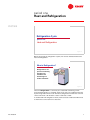
period one
Heat and Refrigeration
notes
5HIULJHUDWLRQ&\FOH
SHULRGRQH
+HDWDQG5HIULJHUDWLRQ
Figure 2
Before discussing the refrigeration system, we need to understand the terms
heat and refrigeration.
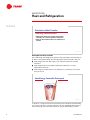
:KDWLV5HIULJHUDWLRQ"
5HIULJHUDWLRQLVWKH
SURFHVVRIUHPRYLQJ
KHDWIURPRQH
VXEVWDQFHDQG
WUDQVIHUULQJLWWR
DQRWKHUVXEVWDQFH
Figure 3
The term refrigeration is commonly associated with something cold. A
household refrigerator, for example, keeps food cold. It accomplishes this task
by removing heat from the food. Therefore, refrigeration involves the removal
of heat. The word cold describes a state of low heat content.
To understand how refrigeration works, we first need to understand what heat
is and how it is removed from a substance.
TRG-TRC003-EN
1
period one
Heat and Refrigeration
notes
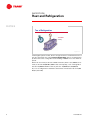
:KDWLV+HDW"
+HDWLVDIRUPRIHQHUJ\
Figure 4
What is Heat?
Heat is a form of energy. Every object on earth contains heat energy in both
quantity and intensity.
4XDQWLW\DQG,QWHQVLW\
Figure 5
Heat intensity is measured by its temperature, commonly in either degrees
Fahrenheit (°F) or degrees Celsius (°C). If all heat were removed from an
object, the temperature of the object would decrease to -459.6°F [-273.2°C].
This temperature is referred to as “absolute zero” and is the temperature at
which all molecular activity stops.
The quantity of heat contained in an object or substance is not the same as its
intensity of heat. For example, the hot sands of the desert contain a large
quantity of heat, but a single burning candle has a higher intensity of heat.
2
TRG-TRC003-EN
period one
Heat and Refrigeration
notes
4XDQWLW\DQG,QWHQVLW\
)
)
>&@
>&@
Figure 6
These two different masses of water contain the same quantity of heat, yet the
temperature of the water on the left is higher. Why? The water on the left
contains more heat per unit of mass than the water on the right. In other words,
the heat energy within the water on the left is more concentrated, or intense,
resulting in the higher temperature. Note that the temperature of a substance
does not reveal the quantity of heat that it contains.
0HDVXULQJ+HDW4XDQWLW\
OE
OE
ZDWHU
%WX
)
NJ
ZDWHU
NFDO
&
)
&
Figure 7
In the English system of units, the quantity of heat is measured in terms of the
British Thermal Unit (Btu). The Btu is defined as the quantity of heat energy
required to raise the temperature of 1 lb of water by 1°F.
Similarly, in the metric system of units, the quantity of heat is measured in
terms of the kilocalorie (kilogram-calorie or kcal). The kcal is defined as the
amount of heat energy required to raise the temperature of 1 kg of water 1°C.
Alternatively, in the Systeme International (SI) metric system, heat quantity can
be expressed using the unit kiloJoule (kJ). One kcal is equal to 4.19 kJ.
TRG-TRC003-EN
3
period one
Heat and Refrigeration
notes
3ULQFLSOHVRI+HDW7UDQVIHU
s
+HDWHQHUJ\FDQQRWEHGHVWUR\HG
s
+HDWDOZD\VIORZVIURPDKLJKHUWHPSHUDWXUH
VXEVWDQFHWRDORZHUWHPSHUDWXUHVXEVWDQFH
s
+HDWFDQEHWUDQVIHUUHGIURPRQHVXEVWDQFHWR
DQRWKHU
Figure 8
Principles of Heat Transfer
Air-conditioning and refrigeration systems use the principles of heat transfer to
produce cooling and heating. The three principles discussed in this clinic are:
■
Heat energy cannot be destroyed; it can only be transferred to another
substance
■
Heat energy flows from a higher temperature substance to a lower
temperature substance
■
Heat energy is transferred from one substance to another by one of three
basic processes
+HDW(QHUJ\&DQQRW%H'HVWUR\HG
Figure 9
To produce cooling, heat must be removed from the substance by transferring
it to another substance. The first principle to discuss regarding heat transfer is
that heat energy cannot be destroyed; it can only be transferred to another
4
TRG-TRC003-EN
period one
Heat and Refrigeration
notes
substance. This is commonly referred to as the principle of “conservation of
energy.”
Ice cubes are typically placed in a beverage to cool it before it is served. As heat
is transferred from the beverage to the ice, the temperature of the beverage is
lowered. The heat removed from the beverage is not destroyed but instead is
absorbed by the ice, changing the ice from a solid to a liquid.
+HDW)ORZVIURP+RWWR&ROG
Figure 10
The second principle is that heat naturally flows from a higher temperature
substance to a lower temperature substance; in other words, from hot to cold.
Heat cannot flow from a cold substance to a hot substance.
Consider the example of the beverage and the ice cubes. As long as the
temperature of the beverage is higher than the temperature of the ice cubes,
heat will always flow from the beverage to the ice cubes.
TRG-TRC003-EN
5
period one
Heat and Refrigeration
notes
0HWKRGVRI+HDW7UDQVIHU
FRQYHFWLRQ
ZDUPDLU
UDGLDWLRQ
KRW
ZDWHU
FRQGXFWLRQ
FRRODLU
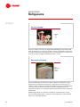
Figure 11
The third principle is that heat is transferred from one substance to another by
one of three basic processes: conduction, convection, and radiation. The device
shown is a baseboard convector that is commonly used for heating a space. It
can be used to demonstrate all three processes of transferring heat.
Hot water flows through a tube inside the convector, warming the inside
surface of the tube. Heat is transferred, by conduction, through the tube wall to
the slightly cooler fins that are attached to outside surface of the tube.
Conduction is the process of transferring heat through a solid.
The heat is then transferred to the cool air that comes into contact with the fins.
As the air is warmed and becomes less dense, it rises, carrying the heat away
from the fins and out of the convector. This air movement is known as a
convection current. Convection is the process of transferring heat as the result
of the movement of a fluid. Convection often occurs as the result of the natural
movement of air caused by temperature (density) differences.
Additionally, heat is radiated from the warm cabinet of the convector and
contacts cooler objects within the space. Radiation is the process of
transferring heat by means of electromagnetic waves, emitted due to the
temperature difference between two objects. An interesting thing about
radiated heat is that it does not heat the air between the source and the object it
contacts; it only heats the object itself.
6
TRG-TRC003-EN
period one
Heat and Refrigeration
notes
5DWHRI+HDW)ORZ
Figure 12
In refrigeration, as in heating, emphasis is placed on the rate of heat transfer,
that is, the quantity of heat that flows from one substance to another within a
given period of time. This rate of heat flow is commonly expressed in terms of
Btu/hr—the quantity of heat, in Btus, that flows from one substance to another
over a period of 1 hour.
Similarly, in the SI metric system of units, the rate of heat flow is expressed in
terms of kilowatts (kW), which are equivalent to kJ/sec. Kilowatts describe the
quantity of heat, in kJ, that flows from one substance to another over a period
of 1 second.
TRG-TRC003-EN
7
period one
Heat and Refrigeration
notes
7RQRI5HIULJHUDWLRQ
%WXKU
>N:@
Figure 13
In the English system of units, there is a larger and more convenient measure of
the rate of heat flow. It is called a ton of refrigeration. One ton of refrigeration
produces the same cooling effect as the melting of 2000 lb of ice over a 24-hour
period.
When 1 lb of ice melts, it absorbs 144 Btu. Therefore, when 1 ton (2000 lb) of ice
melts, it absorbs 288,000 Btu (2000 x 144). Consequently, 1 ton of refrigeration
absorbs 288,000 Btu within a 24-hour period or 12,000 Btu/hr (288,000/24).
So, 1 ton of refrigeration is defined as the transfer of heat at the rate of 12,000
Btu/hr [3.517 kW].
8
TRG-TRC003-EN
period two
Refrigerants
notes
5HIULJHUDWLRQ&\FOH
SHULRGWZR
5HIULJHUDQWV
Figure 14
In this period we will discuss refrigerants, the substances used to absorb and
transfer heat for the purpose of cooling.
,FHDVD&RRODQW
LFHPHOWVDW
)
>&@
Figure 15
Ice can be used to preserve food. Because heat flows from a higher temperature
substance to a lower temperature substance, ice can be used in a frozen display
case to absorb heat from the relatively warm food, cooling the food. As the ice
absorbs heat, it melts and is drained away.
Used in this manner, ice is a coolant. It absorbs heat from the food and
transports the heat away from the food.
TRG-TRC003-EN
9
period two
Refrigerants
notes
,FHDVD&RRODQW
LFHPHOWVDW
)
>&@
Figure 16
Pure ice, however, does have an important disadvantage. It absorbs heat and
melts at 32°F [0°C]. Ice cream, for example, melts at a temperature lower than
32°F [0°C]. In the same frozen display case, ice cannot keep the ice cream frozen
because ice melts at a higher temperature than ice cream.
'U\,FHDVD&RRODQW
GU\LFH
HYDSRUDWHVDW
)
>&@
Figure 17
There is another type of ice known as dry ice, which is solid (frozen) carbon
dioxide (CO2). It evaporates directly from a solid phase to a vapor phase at
-109.4°F [-78.6°C]. Used in the same frozen display case, dry ice would keep the
ice cream frozen because it evaporates at a lower temperature than the
temperature at which ice cream melts, but would result in an unnecessarily low
temperature.
Additionally, both pure ice and dry ice would be consumed in the cooling
process, either melting away as a liquid or evaporating into a vapor. It would
have to be continually replaced.
10
TRG-TRC003-EN
period two
Refrigerants
notes
5HIULJHUDQW
5ERLOVDW
)
>&@
Figure 18
Finally, Refrigerant-22 (R-22) is a chemical used in many refrigeration systems.
If, hypothetically, an open container of liquid R-22 were placed in the frozen
display case, when exposed to atmospheric pressure, it would absorb heat and
boil violently at -41.4°F [-40.8°C].
This is a hypothetical example because chemical refrigerants have
environmental regulations that legally require the refrigeration system to be
sealed. Any loss of refrigerant to the atmosphere is closely monitored and,
generally speaking, not allowed.
At atmospheric pressure, each of these three substances (pure ice, dry ice, and
R-22) absorbs heat and changes phase at its own fixed temperature. Pure ice
melts at 32°F [0°C], dry ice evaporates at -109.4°F [-78.6°C], and R-22 boils at
-41.4°F [-40.8°C].
Why do we want a substance to change phase while producing refrigeration?
TRG-TRC003-EN
11
period two
Refrigerants
notes
(IIHFWRI7UDQVIHUULQJ+HDW
OE
OE
ZDWHU
NJ
ZDWHU
%WX
)
)
NFDO
&
&
Figure 19
Change of Phase
This question is best answered by examining the effects of heat transfer on
water. Consider 1 lb of 60°F water. By adding or subtracting 1 Btu of heat
energy, the water temperature is raised or lowered by 1°F.
Similarly, by adding or subtracting 1 kcal (4.2 kJ) of heat energy to a 1 kg
container of 15°C water, the water temperature is raised or lowered by 1°C.
(IIHFWRI7UDQVIHUULQJ+HDW
%WX
OE
OE
ZDWHU
)
)
NFDO
NJ
ZDWHU
&
&
Figure 20
Therefore, adding 152 Btu to 1 lb of 60°F water raises its temperature to 212°F.
Although this is the boiling temperature of water at atmospheric pressure,
adding 1 more Btu will not cause all of the water to evaporate.
Similarly, adding 85 kcal (356 kJ) to 1 kg of 15°C water raises its temperature to
100°C. Although this is the boiling temperature of water at atmospheric
pressure, adding 1 more kcal (4.2 kJ) will not cause all of the water to
evaporate.
12
TRG-TRC003-EN
period two
Refrigerants
notes
(IIHFWRI7UDQVIHUULQJ+HDW
%WX
OE
OE
ZDWHU
)
OE
OE
VWHDP
)
NFDO
NJ
ZDWHU
&
NJ
VWHDP
&
Figure 21
In fact, 970.3 Btu must be added to 1 lb of 212°F water to completely transform
it to 1 lb of steam at the same temperature.
Similarly, 244.5.3 kcal (1023 kJ) must be added to 1 kg of 100°C water to
completely transform it to 1 kg of steam at the same temperature.
(IIHFWRI7UDQVIHUULQJ+HDW
%WX
OE
OE
VWHDP
)
OE
OE
ZDWHU
)
NFDO
NJ
VWHDP
&
NJ
ZDWHU
&
Figure 22
Conversely, when 1 lb of 212°F steam condenses, it gives off 970.3 Btu of heat
energy in the process. After the steam condenses completely, the removal of
more heat will begin to lower the temperature of the water below 212°F.
Similarly, when 1 kg of 100°C steam condenses, it gives off 244.5 kcal (1023 kJ)
of heat energy in the process. After the steam condenses completely, the
removal of more heat will begin to lower the temperature of the water below
100°C.
TRG-TRC003-EN
13
period two
Refrigerants
notes
/DWHQW+HDW
OE
OE
VWHDP
OE
OE
ZDWHU
)
%WX
)
NJ
VWHDP
NJ
ZDWHU
&
NFDO
&
Figure 23
The quantity of heat that must be added to the water in order for it to evaporate
cannot be sensed by an ordinary thermometer. This is because both the water
and steam remain at the same temperature during this phase change.
This kind of heat is called latent heat, which is dormant or concealed heat
energy. Latent heat is the energy involved in changing the phase of a
substance—from a liquid to a vapor in this example.
6HQVLEOH+HDW
OE
OE
ZDWHU
NJ
ZDWHU
%WX
)
)
NFDO
&
&
Figure 24
In contrast, sensible heat is heat energy that, when added to or removed from
a substance, results in a measurable change in temperature.
Refrigerants can absorb a significant amount of heat when they change phase;
much more than if they just change temperature. Different substances have
different specific temperatures at which these phase changes occur, and
different quantities of heat are required for this change to take place. They also
14
TRG-TRC003-EN
period two
Refrigerants
notes
have different capacities for absorbing heat. This capacity is a property of the
substance called specific heat.
6SHFLILF+HDW
)
)
>&@
>&@
$
%
Figure 25
Suppose equal quantities of two different liquids, $ and %, both at room
temperature, are heated. The gas burners are lighted and adjusted so that each
is burning exactly the same quantity of gas over the same time period, ensuring
that each container of liquid receives the same quantity of heat. After a period
of time, the thermometer in the container of liquid $ indicates 140°F [60°C],
while the thermometer in the container of liquid % indicates 200°F [93.3°C].
Even though equal quantities of the two liquids were supplied with exactly the
same quantity of heat, why does liquid % reach a higher temperature than
liquid $?
The reason is that liquid % has less capacity for absorbing heat than liquid $.
This capacity for absorbing heat is called specific heat. The specific heat of a
substance is defined as the quantity of heat, in Btus, required to raise the
temperature of 1 lb of that substance 1°F.
Similarly, in metric units, specific heat is defined as the quantity of heat, in kJs,
required to raise the temperature of 1 kg of that substance 1°C.
TRG-TRC003-EN
15
period two
Refrigerants
notes
0RGHUQ5HIULJHUDQWV
Figure 26
Modern Refrigerants
Refrigerants are substances that are used to absorb and transport heat for the
purpose of cooling. When selecting a refrigerant to use for a given application,
in addition to these heat transfer properties the manufacturer considers
efficiency, operating pressures, compatibility with materials, stability, toxicity,
flammability, cost, availability, safety, and environmental impact.
The most common refrigerants used in mechanical refrigeration systems today
are Refrigerant-123 (or R-123), R-134a, and R-22. Ammonia (R-717) and, under
certain operating pressures, even water (R-718) and carbon dioxide (R-744) can
be used as refrigerants.
Refrigerant-22 has been the most widely used refrigerant in residential,
commercial, and industrial applications since the 1940s. For the purposes of
this clinic, it will be used as the refrigerant in the examples.
16
TRG-TRC003-EN
period three
Refrigeration Cycle
notes
5HIULJHUDWLRQ&\FOH
SHULRGWKUHH
5HIULJHUDWLRQ&\FOH
Figure 27
The frozen display case example used in the last period demonstrates that, at a
given pressure, refrigerants absorb heat and change phase at a fixed
temperature. It also shows how these refrigerants are “consumed” in the
cooling process, either melting into a liquid or evaporating into a vapor.
This period discusses how the refrigerant can be recovered and reused to
continue the refrigeration cycle.
5HIULJHUDWLRQ6\VWHP
DLUIORZ
OLTXLGUHIULJHUDQW
5
FROOHFWV
UHIULJHUDQW
YDSRU
)
>&@
Figure 28
A rudimentary refrigeration system could hypothetically be constructed using a
drum of liquid refrigerant at atmospheric pressure, a coil, a collecting drum,
and a valve to regulate the flow of refrigerant into the coil. Opening the valve
allows the liquid refrigerant to flow into the coil by gravity. As warm air is
blown over the surface of the coil, the liquid refrigerant inside the coil will
absorb heat from the air, eventually causing the refrigerant to boil while the air
is cooled. Adjustment of the valve makes it possible to supply just enough
TRG-TRC003-EN
17
period three
Refrigeration Cycle
notes
liquid refrigerant to the coil so that all the refrigerant evaporates before it
reaches the end of the coil.
One disadvantage of this system is that after the liquid refrigerant passes
through the coil and collects in the drum as a vapor, it cannot be reused. The
cost and environmental impacts of chemical refrigerants require the
refrigeration process to continue without loss of refrigerant.
Additionally, the boiling temperature of R-22 at atmospheric pressure is -41.4°F
[-40.8°C]. At this unnecessarily low temperature, the moisture contained in the
air passing through the coil freezes on the coil surface, ultimately blocking it
completely.
5HIULJHUDWLRQ6\VWHP
HYDSRUDWRU
OLTXLG
UHIULJHUDQW
UHIULJHUDQW
YDSRU
"
Figure 29
Closing the Cycle
To solve the first problem, a system is needed to collect this used refrigerant
and return it to the liquid phase. Then the refrigerant can be passed through the
coil again.
This is exactly what happens in a typical mechanical refrigeration system.
Liquid refrigerant absorbs heat and evaporates within a device called an
evaporator. In this example system, air is cooled when it passes through the
evaporator, while the heat is transferred to the refrigerant, causing it to boil and
change into a vapor. As discussed in the previous period, a refrigerant can
absorb a large amount of heat when it changes phase. Because of the
refrigerant changing phase, the system requires far less refrigerant than if the
refrigerant was just increasing in temperature.
The refrigerant vapor must then be transformed back into a liquid in order to
return to the evaporator and repeat the process.
18
TRG-TRC003-EN
period three
Refrigeration Cycle
notes
5HIULJHUDWLRQ6\VWHP
UHIULJHUDQW
YDSRU
KHDW
OLTXLG
UHIULJHUDQW
)
>&@
VXEVWDQFH
FROGHUWKDQ
)
>&@
Figure 30
The liquid refrigerant absorbed heat from the air while it was inside the
evaporator, and was transformed into a vapor in the process of doing useful
cooling. Earlier in this clinic, we demonstrated that if the heat is then removed
from this vapor, it will transform (condense) back to its original liquid phase.
Heat flows from a higher temperature substance to a lower temperature
substance. In order to remove heat from the refrigerant vapor, it must transfer
this heat to a substance that is at a lower temperature. Assume that the
refrigerant evaporated at -41.4°F [-40.8°C]. To condense back into liquid, the
refrigerant vapor must transfer heat to a substance that has a temperature less
than -41.4°F [-40.8°C]. If a substance were readily available at this cooler
temperature, however, the refrigerant would not be required in the first place.
The cooler substance could accomplish the cooling by itself.
How can heat be removed from this cool refrigerant vapor, to condense it, using
a readily-available substance that is already too warm for use as the cooling
medium? What if we could change the temperature at which the refrigerant
vapor condenses back into liquid?
TRG-TRC003-EN
19
period three
Refrigeration Cycle
notes
%RLOLQJ3RLQWRI:DWHU
)
WHPSHUDWXUH
>&@
SVLD
SVLD
>03D@
SUHVVXUH
Figure 31
At higher pressures, refrigerant boils and condenses at higher temperatures.
This can be explained by examining the properties of water.
At atmospheric pressure (14.7 psia [0.10 MPa]), water boils and evaporates at
212°F [100°C]. When pressure is increased, however, water does not boil until it
reaches a much higher temperature. At a higher pressure there is a greater
force pushing against the water molecules, keeping them together in a liquid
phase.
Recall that, at a given pressure, the temperature at which a liquid will boil into a
vapor is the same temperature at which the vapor will condense back into a
liquid.
WHPSHUDWXUH
%RLOLQJ3RLQWRI5HIULJHUDQW
)
>&@
)
>&@
SVLD
SVLD
>03D
>03D@@
SUHVVXUH
SVLD
SVLD
>03D
>03D@@
Figure 32
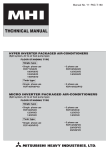
This curve illustrates the pressures and corresponding temperatures at which
R-22 boils and condenses. At a pressure of 85 psia [0.59 MPa], the liquid R-22
will boil at 41.2°F [5.1°C]. As an example, assume that a compressor is used to
20
TRG-TRC003-EN
period three
Refrigeration Cycle
notes
increase the pressure of the resulting refrigerant vapor to 280 psia [1.93 MPa].
This increase in pressure raises the temperature at which the vapor would
condense back into liquid to 121.5°F [49.7°C].
In order to condense the refrigerant vapor at this higher temperature, a
substance at a temperature less than 121.5°F [49.7°C] is needed. Ambient air or
water is generally available at temperatures less than this.
9DSRU&RPSUHVVLRQ&\FOH
H[SDQVLRQ
GHYLFH
HYDSRUDWRU
FRQGHQVHU
FRPSUHVVRU
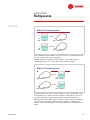
Figure 33
A compressor, condenser, and expansion device form the rest of the system
that returns the refrigerant vapor to a low-temperature liquid, which can again
be used to produce useful cooling. This cycle is called the vapor-compression
refrigeration cycle.
In this cycle, a compressor is used to pump the low-pressure refrigerant vapor
from the evaporator and compress it to a higher pressure.
This hot, high-pressure refrigerant vapor is then discharged into a condenser.
Because heat flows from a substance at a higher temperature to a substance at
a lower temperature, heat is transferred from the hot refrigerant vapor to a
cooler condensing media, which, in this example, is ambient air. As heat is
removed from the refrigerant, it condenses, returning to the liquid phase. This
liquid refrigerant is, however, still at a high temperature.
Finally, an expansion device is used to create a large pressure drop that
lowers the pressure, and correspondingly the temperature, of the liquid
refrigerant. The temperature is lowered to a point where it is again cool enough
to absorb heat in the evaporator.
TRG-TRC003-EN
21
period three
Refrigeration Cycle
notes
%DVLF5HIULJHUDWLRQ6\VWHP
&
GLVFKDUJH
OLQH
FRQGHQVHU
OLTXLG
OLQH
H[SDQVLRQ
GHYLFH
FRPSUHVVRU
%
$
VXFWLRQ
OLQH
'
HYDSRUDWRU
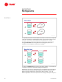
Figure 34
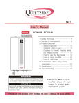
Basic Refrigeration System
This diagram illustrates a basic vapor-compression refrigeration system that
contains the described components. First, notice that this is a closed system.
The individual components are connected by refrigerant piping. The suction
line connects the evaporator to the compressor, the discharge line connects
the compressor to the condenser, and the liquid line connects the condenser
to the evaporator. The expansion device is located in the liquid line.
Recall that the temperature at which refrigerant evaporates and condenses is
related to its pressure. Therefore, regulating the pressures throughout this
closed system can control the temperatures at which the refrigerant evaporates
and then condenses. These pressures are obtained by selecting system
components that will produce the desired balance. For example, select a
compressor with a pumping rate that matches the rate at which refrigerant
vapor is boiled off in the evaporator. Similarly, select a condenser that will
condense this volume of refrigerant vapor at the desired temperature and
pressure.
22
TRG-TRC003-EN
period three
Refrigeration Cycle
notes
(YDSRUDWRU
$
PL[WXUHRI
OLTXLGDQGYDSRU
UHIULJHUDQW
%
UHIULJHUDQW
YDSRU
DLU
Figure 35
At the inlet to the evaporator, the refrigerant exists as a cool, low-pressure
mixture of liquid and vapor. In this example, the evaporator is a finned-tube coil
used to cool air. Other types of evaporators are used to cool water.
The relatively warm air flows across this finned-tube arrangement and the cold
refrigerant flows through the tubes. The refrigerant enters the evaporator ($)
and absorbs heat from the warmer air, causing the liquid refrigerant to boil. The
resulting refrigerant vapor (%) is drawn to the compressor.
&RPSUHVVRU
%
ORZSUHVVXUH
UHIULJHUDQWYDSRU
IURPHYDSRUDWRU
&
KLJKSUHVVXUH
UHIULJHUDQWYDSRU
WRFRQGHQVHU
Figure 36
The compressor raises the pressure of the refrigerant vapor (%) to a pressure
and temperature high enough (&) so that it can reject heat to another fluid, such
as ambient air or water. There are several types of compressors. The type
shown in this figure is a reciprocating compressor.
This hot, high-pressure refrigerant vapor then travels to the condenser.
TRG-TRC003-EN
23
period three
Refrigeration Cycle
notes
&RQGHQVHU
&
UHIULJHUDQW
YDSRU
'
OLTXLG
UHIULJHUDQW
RXWGRRU
DLU
Figure 37
The condenser is a heat exchanger used to reject the heat of the refrigerant to
another medium. The example shown is an air-cooled condenser that rejects
heat to the ambient air. Other types of condensers are used to reject heat to
water.
The hot, high-pressure refrigerant vapor (&) flows through the tubes of this
condenser and rejects heat from the cooler ambient air that passes through the
condenser coil. As the heat content of the refrigerant vapor is reduced, it
condenses into liquid (').
From the condenser, the high-pressure liquid refrigerant travels to the
expansion device.
([SDQVLRQ'HYLFH
$
PL[WXUHRI
OLTXLGDQGYDSRU
UHIULJHUDQW
OLTXLG
UHIULJHUDQW
'
Figure 38
The primary purpose of the expansion device is to drop the pressure of the
liquid refrigerant to equal the pressure in the evaporator. Several types of
expansion devices can be used. The device shown is an expansion valve.
24
TRG-TRC003-EN
period three
Refrigeration Cycle
notes
The high-pressure liquid refrigerant (') flows through the expansion device,
causing a large pressure drop. This pressure drop reduces the refrigerant
pressure, and, therefore, its temperature, to that of the evaporator. At the lower
pressure, the temperature of the refrigerant is higher than its boiling point. This
causes a small portion of the liquid to boil, or flash. Because heat is required to
boil this small portion of refrigerant, the boiling refrigerant absorbs heat from
the remaining liquid refrigerant, cooling it to the desired evaporator
temperature.
The cool mixture of liquid and vapor refrigerant then enters the evaporator ($)
to repeat the cycle.
%DVLF5HIULJHUDWLRQ6\VWHP
KLJKSUHVVXUH
VLGH
&
GLVFKDUJH
OLQH
FRQGHQVHU
OLTXLG
OLQH
%
'
H[SDQVLRQ
GHYLFH
$
HYDSRUDWRU
FRPSUHVVRU
VXFWLRQ
OLQH
ORZSUHVVXUH
VLGH
Figure 39
Placing each component in its proper sequence within the system, the
compressor and expansion device maintain a pressure difference between the
high-pressure side of the system (condenser) and the low-pressure side of the
system (evaporator).
This pressure difference allows two things to happen simultaneously. The
evaporator can be at a pressure and temperature low enough to absorb heat
from the air or water to be cooled, and the condenser can be at a temperature
high enough to permit heat rejection to ambient air or water that is at normally
available temperatures.
These major components are discussed in further detail in the “Refrigeration
Compressors” and “Refrigeration System Components” clinics.
TRG-TRC003-EN
25
period four
Pressure–Enthalpy Chart
notes
5HIULJHUDWLRQ&\FOH
SHULRGIRXU
3UHVVXUH¤(QWKDOS\&KDUW
Figure 40
During this period we will again analyze the basic vapor-compression
refrigeration cycle. However, this time we will use a graphic tool called the
pressure–enthalpy chart.
3UHVVXUH¤(QWKDOS\3¤K&KDUW
HQYHORSH
SUHVVXUH
VXEFRROHG
OLTXLG
OLQHRIFRQVWDQW
WHPSHUDWXUH
PL[WXUHRI
OLTXLGDQG
YDSRU
VDWXUDWHG
YDSRUOLQH
VXSHUKHDWHG
YDSRU
VDWXUDWHG
OLTXLGOLQH
HQWKDOS\
Figure 41
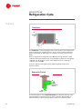
The pressure–enthalpy (P-h) chart plots the properties of a refrigerant—
refrigerant pressure on the vertical axis and enthalpy on the horizontal axis.
Enthalpy is a measure of heat quantity, both sensible and latent, per pound
[kg] of refrigerant. It is typically expressed in terms of Btu/lb [kJ/kg].
The right-hand side of the chart indicates the conditions at which the refrigerant
will be in the vapor phase. The left-hand side of the chart indicates the
conditions at which the refrigerant will be in the liquid phase. In the middle of
the chart is an envelope (curve). The left-hand boundary of the envelope
indicates the saturated liquid condition. The right-hand boundary indicates the
saturated vapor condition. If the enthalpy of the refrigerant lies inside the
26
TRG-TRC003-EN
period four
Pressure–Enthalpy Chart
notes
envelope, the refrigerant exists as a mixture of liquid and vapor. If the enthalpy
of the refrigerant lies to the right of the envelope, the vapor is superheated.
Similarly, if the enthalpy of the refrigerant lies to the left of the envelope, the
liquid is subcooled.
Lines of constant temperature cross the P–h chart as shown.
3¤K&KDUWIRU:DWHU
)
)
>&@
SUHVVXUH
>&@
SVLD
SVLD
>03D
>03D@@
)
>&@
$
%
&
HQWKDOS\
'
:DWHU
Figure 42
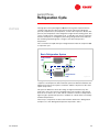
To further demonstrate the use of the P–h chart, let us look at the process of
heating and boiling water, at a constant pressure, on a P–h chart for water.
As discussed earlier, at atmospheric pressure (14.7 psia [0.10 MPa]) water boils
at 212°F [100°C]. At $, the water temperature is 180°F [82.2°C]. As we add heat
to the water, the temperature and enthalpy of the water increas as they move
toward %. When the water reaches its saturated condition (%), at 212°F [100°C],
it starts to boil and transform into vapor. As more heat is added to the water, it
continues to boil while the temperature remains constant. A greater percentage
of the water is transforming into vapor as it moves toward &.
When the water reaches & on the saturation vapor line, it has completely
transformed into vapor. Now, as more heat is added to the vapor, its
temperature begins to increase again toward D, 240°F [115.6°C].
TRG-TRC003-EN
27
period four
Pressure–Enthalpy Chart
notes
+HDWRI9DSRUL]DWLRQIRU:DWHU
VXEFRROHG
OLTXLG
SUHVVXUH
PL[WXUHRI
OLTXLGDQG
YDSRU
KHDWRI
YDSRUL]DWLRQ
SVLD
SVLD
%
>03D
>03D@@
&
VXSHUKHDWHG
YDSRU
%WXOE
%WXOE HQWKDOS\ %WXOE
%WXOE
>N-NJ@
:DWHU
Figure 43
>N-NJ@
The distance between the edges of the envelope indicates the quantity of heat
required to transform saturated liquid into saturated vapor at a given pressure.
This is called the heat of vaporization.
For example, B represents the enthalpy of saturated liquid water at 14.7 psia
[0.10 MPa] and C represents the enthalpy of saturated water vapor at the same
pressure. The difference in enthalpy between B and C—970 Btu/lb
[2256.3 kJ/kg]—is the heat of vaporization for water at this pressure.
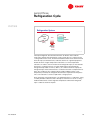
(YDSRUDWRU
SUHVVXUH
UHIULJHUDWLRQ
HIIHFW
SVLD
SVLD
>03D
>03D@@
)
>&@
$
HYDSRUDWRU
HQWKDOS\
%
&
5HIULJHUDQW
Figure 44
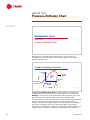
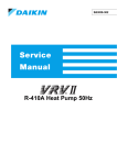
The P-h chart can be used to analyze the vapor-compression refrigeration cycle
and determine the conditions of the refrigerant at any point in the cycle. The
chart in this example is for R-22.
Because the refrigeration cycle is a continuous process, defining the cycle can
start at any point. This example begins in the lower left-hand portion of the P-h
chart, where the refrigerant enters the evaporator.
28
TRG-TRC003-EN
period four
Pressure–Enthalpy Chart
notes
At the inlet to the evaporator, the refrigerant is at a pressure of 85 psia
[0.59 MPa] and a temperature of 41.2°F [5.1°C], and is a mixture of liquid and
vapor (mostly liquid). This cool, low-pressure refrigerant enters the evaporator
($) where it absorbs heat from the relatively warm air that is being cooled. This
transfer of heat boils the liquid refrigerant inside the evaporator and
superheated refrigerant vapor is drawn to the compressor (&).
The change in enthalpy from A to C that occurs inside the evaporator is called
the refrigeration effect. This is the amount of heat that each pound [kg] of
liquid refrigerant will absorb when it evaporates.
SUHVVXUH
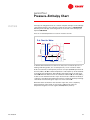
6XSHUKHDW
)
>&@
>&@
%
$
^
SVLD
SVLD
>03D
>03D@@
)
&
VXSHUKHDW
HQWKDOS\
Figure 45
Compressors are designed to compress vapor. Liquid refrigerant can cause
damage if drawn into the compressor. In some refrigeration systems additional
heat is added to the saturated vapor (%) in the evaporator to ensure that no
liquid is present at the compressor inlet. This additional amount of heat, above
saturation, is called superheat. This superheated vapor (&) is generally 8°F to
12°F [4.4°C to 6.7°C] above the saturated vapor condition when it enters the
compressor. In this example, the refrigerant vapor is superheated 10°F [5.6°C],
from 41.2°F [5.1°C] to 51.2°F [10.7°C].
TRG-TRC003-EN
29
period four
Pressure–Enthalpy Chart
notes
&RPSUHVVRU
SUHVVXUH
'
FRPSUHVVRU
%
$
&
HQWKDOS\
Figure 46
The compressor draws in the superheated refrigerant vapor (&) and
compresses it to a pressure and temperature (') high enough that it can reject
heat to another fluid. As the volume of the refrigerant is reduced by the
compressor, its pressure is increased. Additionally, the mechanical energy used
by the compressor to accomplish this task is converted to heat energy. This
causes the temperature of the refrigerant to also rise as its pressure is
increased.
SUHVVXUH
+HDWRI&RPSUHVVLRQ
'
SVLD
SVLD
>03D
>03D@@
)
>&@
)
>&@
SVLD
SVLD
>03D
>03D@@
%
$
HQWKDOS\
&
KHDWRI
FRPSUHVVLRQ
Figure 47
When the refrigerant vapor is discharged from the compressor, its temperature
is substantially higher than its saturation temperature (the temperature at
which the refrigerant would condense). The increase in enthalpy from & to ' is
due to heat added by the compressor, or the heat of compression.
In this example, the refrigerant leaves the compressor at 280 psia [1.93 MPa]
and 191.5°F [88.6°C]. At this higher pressure, the corresponding saturation
30
TRG-TRC003-EN
period four
Pressure–Enthalpy Chart
notes
temperature is 121.5°F [49.7°C]. The refrigerant vapor leaving the compressor
is therefore 70°F [38.9°C] above its saturation temperature.
This hot, high-pressure refrigerant vapor then travels to the condenser.
&RQGHQVHU
SVLD
SVLD
>03D
>03D@@
*
)
>&@
FRQGHQVHU
^
SUHVVXUH
VXEFRROLQJ
)
'
(
)
>&@
%
$
HQWKDOS\
&
Figure 48
Inside of the condenser, heat is transferred from the hot, high-pressure
refrigerant vapor (') to relatively cool ambient air. This reduction in the
enthalpy of the refrigerant vapor causes it to desuperheat. It becomes saturated
vapor, condenses into saturated liquid, and further subcools before leaving the
condenser (*) to go to the expansion device.
First, the refrigerant vapor is cooled (the line from ' to () to its saturation
temperature of 121.5°F [49.7°C]. Next, as additional heat is removed by the
condenser, the refrigerant vapor condenses to its saturated liquid condition (the
line from ( to )). This saturated liquid refrigerant now passes through the area
of the condenser called the subcooler. Here, the liquid refrigerant is further
cooled (the line from ) to *), in this example, to 110°F [43.3°C]. Because the
saturation temperature at the condensing pressure is 121.5°F [49.7°C], the
refrigerant has been subcooled 11.5°F [6.4°C].
With the temperature of the refrigerant in the condenser this high, air at normal
ambient conditions can be used to absorb the heat from the refrigerant. From
the condenser, the high-pressure, subcooled liquid refrigerant (*) travels to the
expansion device.
TRG-TRC003-EN
31
period four
Pressure–Enthalpy Chart
notes
([SDQVLRQ'HYLFH
SUHVVXUH
'
(
*
)
H[SDQVLRQ
GHYLFH
%
$
HQWKDOS\
&
Figure 49
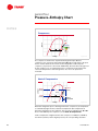
The primary purpose of the expansion device is to drop the pressure of the
liquid refrigerant to equal the evaporator pressure. At this lower pressure, the
refrigerant is now inside the saturation envelope where it exists as a mixture of
liquid and vapor.
The high-pressure liquid refrigerant (*) flows through the expansion device,
causing a large pressure drop. This pressure drop reduces pressure and
temperature of the refrigerant to that of the evaporator ($). At the lower
pressure, the temperature of the refrigerant is higher than its boiling point. This
causes a small portion of the liquid to boil, or flash. Because heat is required to
boil this small portion of refrigerant, boiling refrigerant absorbs heat from the
remaining liquid refrigerant, cooling it to the evaporator temperature. Notice
that there is no change in enthalpy during the expansion process.
The purpose of subcooling the liquid refrigerant in the condenser is to avoid
flashing the refrigerant before it reaches the expansion device. If a valve is used
as the expansion device, the presence of refrigerant vapor can cause improper
operation and premature failure.
32
TRG-TRC003-EN
period four
Pressure–Enthalpy Chart
notes
([SDQVLRQ'HYLFH
)
SUHVVXUH
>&@
'
(
*
SVLD
SVLD
)
>03D
>03D@@
SVLD
SVLD
%
$
>03D
>03D@@
%WXOE
%WXOE
>N-NJ@
%WXOE
%WXOE
>N-NJ@
HQWKDOS\
&
%WXOE
%WXOE
>N-NJ@
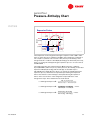
Figure 50
The temperature of the refrigerant entering the expansion device (*) is 110°F
[43.3°C] and its pressure is 280 psia [1.93 MPa]. (The refrigerant condensed at
121.5°F [49.7°C] and was subcooled to 110°F [43.3°C].) The enthalpy of the
refrigerant at this condition is 42.4 Btu/lb [98.6 kJ/kg]. As mentioned previously,
there is no change in enthalpy during the expansion process—it is the same at
both * and $.
The refrigerant leaves the expansion device ($) at evaporator conditions,
85 psia [0.59 MPa] and 41.2°F [5.1°C]. At this pressure, the enthalpy of saturated
liquid is 21.8 Btu/lb [50.7 kJ/kg] and the enthalpy of saturated vapor is
108.2 Btu/lb [251.7 kJ/kg]. Because there is no change of enthalpy during the
expansion process, the mixture of liquid and vapor leaving the expansion
device must have the same enthalpy as the liquid entering the expansion
device. This is true if 76.2% of the refrigerant is liquid and 23.8% of the
refrigerant is vapor. This is determined as shown below:
h A – h saturated liquid
% of Refrigerant Vapor at A = h saturated vapor – h saturated liquid
42.4 Btu/lb – 21.8 Btu/lb
% of Refrigerant Vapor at A = = 23.8%
108.2 Btu/lb – 21.8 Btu/lb
98.6 kJ/kg – 50.7 kJ/kg
% of Refrigerant Vapor at A = = 23.8%
251.7 kJ/kg – 50.7 kJ/kg
TRG-TRC003-EN
33
period four
Pressure–Enthalpy Chart
notes
5HIULJHUDWLRQ&\FOH
)
SUHVVXUH
>&@
SVLD
SVLD
>03D
>03D@@
SVLD
SVLD
>03D
>03D@@
FRQGHQVHU
*
H[SDQVLRQ
GHYLFH
$
)
'
)
>&@
)
>&@
HYDSRUDWRU
)
(
FRPSUHVVRU
%
& )
>&@
>&@
HQWKDOS\
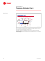
Figure 51
This cool mixture of liquid and vapor refrigerant leaving the expansion device
then enters the evaporator ($) to repeat the cycle.
The vapor-compression refrigeration cycle has successfully recovered the
refrigerant that boiled in the evaporator and converted it back into a cool liquid
to be used again.
34
TRG-TRC003-EN
period five
Review
notes
5HIULJHUDWLRQ&\FOH
SHULRGILYH
5HYLHZ
Figure 52
We will now review the main concepts that were covered in this clinic reagrding
the vapor-compression refrigeration cycle.
5HYLHZ¥3HULRG2QH
s
+HDWLVDIRUPRIHQHUJ\
s
+HDWFDQYDU\LQTXDQWLW\DQGLQWHQVLW\
s
+HDWHQHUJ\FDQQRWEHGHVWUR\HG
s
+HDWFDQEHWUDQVIHUUHGIURPRQHVXEVWDQFHWR
DQRWKHU
s
+HDWDOZD\VIORZVIURPDKLJKHUWHPSHUDWXUH
VXEVWDQFHWRDORZHUWHPSHUDWXUHVXEVWDQFH
s
5HIULJHUDWLRQLVDPHWKRGRIUHPRYLQJKHDW
Figure 53
Period One introduced the concept of heat and how it is transferred from one
substance to another.
Recall that heat is a form of energy and can vary in both quantity and intensity
(temperature). Heat energy cannot be destroyed, however, it can be transferred
to another substance. Heat flows from a higher temperature substance to a
lower temperature substance.
Refrigeration is a method of removing heat.
TRG-TRC003-EN
35
period five
Review
notes
5HYLHZ¥3HULRG7ZR
VHQVLEOH
KHDW
ZDWHU
%WXOE
%WXOE
>NFDONJ@
)
)
>&@
ODWHQW
KHDW
ZDWHU
ZDWHU
>&@
%WXOE
%WXOE
VWHDP
>NFDONJ@
)
)
>&@
>&@
Figure 54
Period Two discussed refrigerants and how they are used in the process of
removing and transporting heat.
Remember that refrigerants absorb significant amounts of heat when they
change phase (e.g., from a liquid to a vapor). Chemical refrigerants commonly
evaporate at low temperatures when exposed to atmospheric pressure.
Because of their cost and impact to the environment, however, refrigerants
must be recovered in a closed system.
5HYLHZ¥3HULRG7KUHH
FRQGHQVHU
H[SDQVLRQ
GHYLFH
FRPSUHVVRU
HYDSRUDWRU
Figure 55
Period Three presented the basic vapor-compression refrigeration cycle, and
specifically the use of a compressor, condenser, and expansion device to
“recover” the evaporated refrigerant and complete the cycle. The primary
components of the vapor-compression refrigeration cycle include the
evaporator, compressor, condenser, and expansion device.
36
TRG-TRC003-EN
period five
Review
notes
Refrigerant enters the evaporator as a cool, low-pressure mixture of liquid and
vapor. It absorbs heat—from the relatively warm air or water to be cooled—and
boils. The cool, low-pressure vapor is then pumped from the evaporator by the
compressor. This increases the pressure and temperature of the refrigerant
vapor. The resulting hot, high-pressure refrigerant vapor enters the condenser
where it rejects heat to ambient air or water that is at a lower temperature, and
condenses into a liquid.
This liquid refrigerant flows from the condenser to the expansion device. The
expansion device creates a pressure drop that reduces the pressure of the
refrigerant to that of the evaporator. At this low pressure, a small portion of the
refrigerant boils off, cooling the remaining liquid refrigerant to the evaporator
temperature. The cool mixture of liquid and vapor refrigerant travels to the
evaporator where it absorbs heat and boils, repeating the cycle.
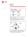
5HYLHZ¥3HULRG)RXU
SUHVVXUH
FRQGHQVHU
H[SDQVLRQ
GHYLFH
FRPSUHVVRU
HYDSRUDWRU
HQWKDOS\
Figure 56
Period Four discussed the use of the pressure–enthalpy (P–h) chart to analyze
the refrigeration system.
The pressure–enthalpy chart plots the properties of a refrigerant—pressure
versus enthalpy. Enthalpy is a measure of heat quantity per pound [kg] of
refrigerant. The chart includes an envelope (curve) that indicates when the
refrigerant exists as a subcooled liquid (to the left of the envelope), a mixture of
liquid and vapor (inside the envelope), or a superheated vapor (to the right of
the envelope).
TRG-TRC003-EN
37
period five
Review
notes
Figure 57
For more information, refer to the following references:
■
Trane Air Conditioning Manual
■
Trane Reciprocating Refrigeration Manual
■
ASHRAE Handbook – Fundamentals
■
ASHRAE Handbook – Refrigeration
■
ASHRAE Handbook – Systems and Equipment
Visit the ASHRAE Bookstore at www.ashrae.org.
For more information on additional educational materials available from Trane,
contact your local Trane office (request a copy of the Educational Materials
catalog – Trane order number EM-ADV1) or visit our online bookstore at
www.trane.com/bookstore/.
38
TRG-TRC003-EN
Quiz
Questions for Period 1
1 Heat intensity is measured in terms of its __________?
2 Heat quantity is measured with units of __________?
3 Heat always flows from a substance of ________ (higher, lower) temperature
to a substance of ________ (higher, lower) temperature.
4 What are the three basic processes by which heat is transferred from one
substance to another?
Questions for Period 2
5 Which process requires more heat energy: raising the temperature of a
container of water from 50°F [10°C] to 200°F [93.3°C] or boiling the same
quantity of 212°F [100°C] water to 212°F [100°C] steam?
6 What type of heat energy, when added to or removed from a substance,
results in a measurable change in temperature?
7 What type of heat energy, when added to or removed from a substance,
results in a change of state of the substance—from a liquid to a vapor or
vice-versa?
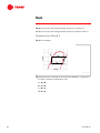
Questions for Period 3
&
%
'
$
Figure 58
8 Identify the four major components of the vapor-compression refrigeration
cycle labeled in Figure 58.
9 What is the state of the refrigerant when it enters the evaporator?
TRG-TRC003-EN
39
Quiz
10 What is the state of the refrigerant when it enters the compressor?
11 What is the state of the refrigerant when it enters the expansion device?
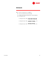
Questions for Period 4
12 What is enthalpy?
&
SUHVVXUH
'
%
$
HQWKDOS\
Figure 59
13 Using the pressure–enthalpy chart in Figure 59, identify the components of
the vapor-compression refrigeration cycle:
a
$ to %
b & to '
c
% to &
d ' to $
40
TRG-TRC003-EN
SUHVVXUH
Quiz
(
* )
SVLD
SVLD
'
>03D
>03D@@
SVLD
SVLD
>03D
>03D@@
+
%
$
&
HQWKDOS\
Figure 60
14 Referring to Figure 60 and given the following conditions,
A - 44.5°F, 90 psia, 41.6 Btu/lb [6.9°C, 0.62 MPa, 96.8 kJ/kg]
B - 44.5°F, 90 psia, 108.5 Btu/lb [6.9°C, 0.62 MPa, 252.4 kJ/kg]
C - 54.5°F, 90 psia, 110.3 Btu/lb [12.5°C, 0.62 MPa, 256.6 kJ/kg]
D - 190°F, 280 psia, 128.4 Btu/lb [87.8°C, 1.93 MPa, 298.7 kJ/kg]
E - 121.5°F, 280 psia, 112.8 Btu/lb [49.7°C, 1.93 MPa, 262.4 kJ/kg]
F - 121.5°F, 280 psia, 46.2 Btu/lb [49.7°C, 1.93 MPa, 107.5 kJ/kg]
G - 107.5°F, 280 psia, 41.6 Btu/lb [41.9°C, 1.93 MPa, 96.8 kJ/kg]
H - 44.5°F, 90 psia, 22.7 Btu/lb [6.9°C, 0.62 MPa, 52.8 kJ/kg]
a
How much superheat is in this system?
b How much subcooling is in this system?
c
What is the refrigeration effect of this system?
d At the inlet to the evaporator, what percentage of the refrigerant exists
as a vapor?
TRG-TRC003-EN
41
Answers
1 Temperature or degrees Fahrenheit [degrees Celsius]
2 British Thermal Unit (Btu) [kilocalorie (kcal) or kiloJoule (kJ)]
3 Higher to lower
4 Conduction, convection, and radiation
5 Boiling the water requires more energy–970.3 Btu/lb [244.5 kJ/kg]. Raising
the temperature of the water from 50°F [10°C] to 200°F [93.3°C] requires
150 Btu/lb [83.3 kJ/kg].
6 Sensible heat
7 Latent heat
8 a
evaporator
b compressor
c
condenser
d expansion device
9 A mixture of liquid and vapor
10 Vapor (possibly superheated vapor)
11 Liquid (possibly subcooled liquid)
12 The measure of heat quantity, both sensible and latent, per pound [kg] of
refrigerant
13 a
evaporator
b condenser
c
compressor
d expansion device
42
TRG-TRC003-EN
Answers
14 a
10°F [5.6°C] (temperature rise from % to &)
b 14°F [7.8°C] (temperature drop from ) to *)
c
68.7 Btu/lb [159.8 kJ/kg] (enthalpy difference between $ and &)
d 22% refrigerant vapor
Enthalpy at A – Enthalpy at H
% of Refrigerant Vapor at A = Enthalpy at B – Enthalpy at H
41.6 Btu/lb – 22.7 Btu/lb
% of Refrigerant Vapor at A = = 22%
108.5 Btu/lb – 22.7 Btu/lb
96.8 kJ/kg – 52.8 kJ/kg
% of Refrigerant Vapor at A = = 22%
252.4 kJ/kg – 52.8 kJ/kg
TRG-TRC003-EN
43
Glossary
ASHRAE American Society of Heating, Refrigerating and Air-Conditioning
Engineers
British Thermal Unit (Btu) A measure of heat quantity, defined as the quantity
of heat energy required to change the temperature of 1 lb of water by 1°F.
compressor A mechanical device in the refrigeration system used to increase
the pressure and temperature of the refrigerant vapor.
condenser A component of the refrigeration system where refrigerant vapor is
converted to liquid as it rejects heat to air, water, or some other fluid.
conduction
The process of transferring heat through a solid.
convection The process transferring heat through the movement of a fluid,
often through the natural movement of air, caused by temperature (density)
differences.
discharge line Pipe that transports refrigerant vapor from the compressor to
the condenser in a mechanical refrigeration system.
enthalpy A measure of heat quantity, both sensible and latent, per pound [kg]
of refrigerant.
evaporator A component of the refrigeration system where cool, liquid
refrigerant absorbs heat from air, water, or some other fluid, causing the
refrigerant to boil.
expansion device A component of the refrigeration system used to reduce the
pressure and temperature of the refrigerant to the evaporator conditions.
flash The process of liquid refrigerant being vaporized by a sudden reduction
of pressure.
heat of compression The amount of heat added to the refrigerant vapor by the
compressor during the process of raising the pressure of the refrigerant to
condenser conditions.
heat of vaporization The amount of heat required to transform (evaporate)
saturated liquid refrigerant to a saturated vapor, at a given pressure.
kilocalorie A measure of heat quantity, defined as the quantity of heat energy
required to change the temperature of 1 kg of water by 1°C.
latent heat Heat energy that, when added to or removed from a substance,
results in a change of state of the substance–from a liquid to a vapor, from a
solid to a liquid, or vice-versa.
liquid line Pipe that transports refrigerant vapor from the condenser to the
evaporator in a mechanical refrigeration system.
pressure–enthalpy chart A graphical representation of the properties of a
refrigerant, plotting refrigerant pressure versus enthalpy.
44
TRG-TRC003-EN
Glossary
radiation The process transferring heat by means of electromagnetic waves
emitted due to the temperature difference between two objects.
refrigerant A substance used to absorb and transport heat for the purpose of
cooling.
refrigeration effect The change in enthalpy that occurs inside the evaporator a
refrigeration cycle that indicates the amount of heat that each pound [kg] of
liquid refrigerant will absorb when it evaporates.
sensible heat Heat energy that, when added to or removed from a substance,
results in a measurable change in temperature.
specific heat The property of a substance describing its capacity for absorbing
heat.
subcooling The amount of heat removed from the liquid refrigerant after it
has completely condensed within the condenser.
suction line Pipe that transports refrigerant vapor from the evaporator to the
compressor in a mechanical refrigeration system.
superheat The amount of heat added to the refrigerant vapor after it has
completely vaporized within the evaporator.
ton of refrigeration A measure of the rate of heat flow, defined as a transfer of
12,000 Btu/hr [3.517 kW].
TRG-TRC003-EN
45
Literature Order Number
The Trane Company
Worldwide Applied Systems Group
3600 Pammel Creek Road
La Crosse, WI 54601-7599
www.trane.com
An American Standard Company
TRG-TRC003-EN
File Number
E/AV-FND-TRG-TRC003-1299-EN
Supersedes
2803-1-1079
Stocking Location
Inland-La Crosse
Since The Trane Company has a policy of continuous product improvement, it reserves the right to change
design and specifications without notice.