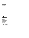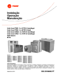
1
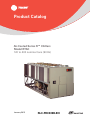
Product Catalog
Air-Cooled Series R™ Chillers
Model RTAC
120 to 400 nominal tons (50 Hz)
January 2015
RLC-PRC039B-EN
Introduction
Like its chillers,Trane wants its relationships with customers to last.Trane is interested in
maintaining long term, loyal relationships.This perspective means the point in time that a
customer purchases a chiller is the beginning of a relationship, not the end.Your business is
important, but your satisfaction is paramount.
The RTAC offers high reliability coupled with proven Series R performance.
The Series R Model RTAC is an industrial grade design built for both the industrial and commercial
markets. It is ideal for schools, hospitals, retailers, office buildings, Internet service providers and
manufacturing facilities.
Copyright
This document and the information in it are the property ofTrane, and may not be used or
reproduced in whole or in part without written permission.Trane reserves the right to revise this
publication at any time, and to make changes to its content without obligation to notify any person
of such revision or change.
Trademarks
All trademarks referenced in this document are the trademarks of their respective owners.
Revision History
RLC-PRC039B-EN (15 Jan 2015)
The following points describe the changes to this revision on the manual:
•
Updated electrical data and customer wiring information
•
Rapid RestartTest
•
Add seismic isolator option
•
Added optional tarp information
© 2015Trane All rights reserved
RLC-PRC039B-EN
Table of Contents
Introduction . . . . . . . . . . . . . . . . . . . . . . . . . . . . . . . . . . . . . . . . . . . . . . . . . . . . . . 2
Table of Contents . . . . . . . . . . . . . . . . . . . . . . . . . . . . . . . . . . . . . . . . . . . . . . . . . . 3
Features and Benefits . . . . . . . . . . . . . . . . . . . . . . . . . . . . . . . . . . . . . . . . . . . . . . 4
Application Considerations . . . . . . . . . . . . . . . . . . . . . . . . . . . . . . . . . . . . . . . . . . 7
Model Number Descriptions . . . . . . . . . . . . . . . . . . . . . . . . . . . . . . . . . . . . . . . . 13
General Data
. . . . . . . . . . . . . . . . . . . . . . . . . . . . . . . . . . . . . . . . . . . . . . . . . . . 14
Performance Data
. . . . . . . . . . . . . . . . . . . . . . . . . . . . . . . . . . . . . . . . . . . . . . 18
Controls . . . . . . . . . . . . . . . . . . . . . . . . . . . . . . . . . . . . . . . . . . . . . . . . . . . . . . . . 25
Electrical Data . . . . . . . . . . . . . . . . . . . . . . . . . . . . . . . . . . . . . . . . . . . . . . . . . . . . 28
Electrical Connection
. . . . . . . . . . . . . . . . . . . . . . . . . . . . . . . . . . . . . . . . . . 34
Dimensions . . . . . . . . . . . . . . . . . . . . . . . . . . . . . . . . . . . . . . . . . . . . . . . . . . . . . . 42
Weights . . . . . . . . . . . . . . . . . . . . . . . . . . . . . . . . . . . . . . . . . . . . . . . . . . . . . . . . . 51
Mechanical Specifications . . . . . . . . . . . . . . . . . . . . . . . . . . . . . . . . . . . . . . . . . . 52
Options . . . . . . . . . . . . . . . . . . . . . . . . . . . . . . . . . . . . . . . . . . . . . . . . . . . . . . . . . 53
RLC-PRC039B-EN
3
Features and Benefits
World Class Energy Efficiency
The importance of energy efficiency cannot be understated. Fortunately, ASHRAE has created a
guideline emphasizing its importance. Nonetheless, energy is often dismissed as an operational
cost over which the owner has little control.That perception results in missed opportunities for
energy efficiency, reduced utility bills, and higher profits. Lower utility bills directly affect
profitability. Every dollar saved in energy goes directly to the bottom line.Trane's RTAC is one way
to maximize your profits.
ASHRAE Standard 90.1 and Executive Order
AllTrane air-cooled chillers meet the new efficiency levels mandated by ASHRAE Standard 90.1.
This new standard requires higher efficiencies than past technologies can deliver.The US Federal
Government has adopted standard 90.1 and, in some cases, requires even higher efficiencies.
Federal Executive Order mandates energy consuming devices procured must be in the top 25% of
their class. In the case of chillers, that product standard is ASHRAE 90.1.Trane's RTAC meets and
exceeds the efficiency requirements of 90.1, while the high and extra efficiency RTAC can meet the
"stretch goals" of Executive Order.
Precise Capacity Control
Trane's patented unloading system allows the compressor to modulate infinitely and exactly match
building loads. At the same time chilled water temperatures will be maintained within +/- 1/2ºF
(0.28°C) of setpoint. Screw or scroll chillers with stepped capacity control do well to maintain chilled
water temperatures within 2ºF (1.1°C) of setpoint. Stepped control also results in over cooling
because rarely does the capacity of the machine match the building load.The result can be 10%
higher energy bills.Trane's RTAC optimizes the part load performance of your machine for energy
efficiency, precise control for process applications, and your personal comfort regardless of the
weather outside.
Excellent Reliability
A buildings environment is expected to be comfortable. When it is, no one says a word. If it's not…
that's a different story.The same is true with chillers. No one ever talks about chillers, yet alone
compressors, until they fail, and tenants are uncomfortable and productivity is lost.Trane's helical
rotary compressors have been designed and built to stay running when you need them.
Fewer moving parts
Trane's helical rotary compressors have only two major rotating parts: the male and female rotor.
A reciprocating compressor can have more than 15 times that number of critical parts. Multiples
of pistons, valves, crankshafts, and connecting rods in a reciprocating unit all represent different
failure paths for the compressor. In fact, reciprocating compressors can easily have a failure rate
four times of a helical rotor. Combine that with two to three reciprocating compressors for each
helical rotary compressor on chillers of equal tonnage, and statistics tell you it's a matter of time
before you lose a reciprocating compressor.
Robust components
Helical rotary compressors are precisely machined using state of the art processes from solid metal
bar stock.Tolerances are maintained within a micron or less than a tenth of the diameter of a
human hair.The resulting compressor is a robust yet highly sophisticated assembly capable of
ingesting liquid refrigerant without risk of damage.
4
RLC-PRC039B-EN
Features and Benefits
Condenser coils
Trane's condenser coils are manufactured with the same philosophy as the compressors; they're
built to last. Even though manufacturing processes have allowed thinner and thinner materials in
their assembly, with obvious material and manufacturing savings,Trane's coil material did not
change with the RTAC generation of air cooled chillers. Substantial condenser fins, that do not
require additional coating in non-corrosive environments, contribute to the highest reliability
standards for air-cooled chillers in the industry.
Superior Control
The Adaptive Control™ microprocessor system enhances the air-cooled Series R chiller by
providing the very latest chiller control technology. With the Adaptive Control microprocessor,
unnecessary service calls and unhappy tenants are avoided.The unit is designed not to trip or
unnecessarily shut down. Only when theTracer™ chiller controllers have exhausted all possible
corrective actions and the unit is still violating an operating limit will the chiller shut down. Controls
on other equipment typically shut down the chiller, usually just when it is needed the most.
For example: A typical five year old chiller with dirty coils might trip out on high pressure cutout
on a 100°F (38°C) day in August. A hot day is just when comfort cooling is needed the most. In
contrast, the air-cooled Series R chiller with an Adaptive Control microprocessor will stage fans on,
modulate electronic expansion valves, and modulate slide valve positions as the chiller approaches
a high pressure cutout, thereby keeping the chiller online when you need it the most.
Simple Installation
RLC-PRC039B-EN
•
Factory Installed Flow Switch. Installed in the optimum location in the piping for reduced
chiller installation cost and superior flow sensing, reducing the potential for nuisance trips.
•
Close Spacing Installation.The air-cooled Series R™ Chiller has the tightest recommended
side clearance in the industry, four feet for maximum performance. In situations where
equipment must be installed with less clearance than recommended, which frequently occurs
in retrofit applications, restricted airflow is common. Conventional chillers may not work at all.
However, the air-cooled Series R chiller with Adaptive Control™ microprocessor will make as
much chilled water as possible given the actual installed conditions, stay on line during
unforeseen abnormal conditions, and optimize the unit performance. Consult yourTrane sales
engineer for more details.
•
Factory Testing Means Trouble Free Startup. All air-cooled Series R chillers are given a
complete functional test at the factory.This computer based test program completely checks
the sensors, wiring, electrical components, microprocessor function, communication
capability, expansion valve performance and fans. In addition, each compressor is run and
tested to verify capacity and efficiency. Where applicable, each unit is factory preset to the
customer's design conditions; an example would be leaving liquid temperature setpoint.The
result of this test program is that the chiller arrives at the job site fully tested and ready for
operation.
•
Factory Installed and Tested Controls/Options Speed Installation. All Series R chiller
options, including main power supply disconnect, low ambient control, ambient temperature
sensor, low ambient lockout, communication interface and ice making controls, are factory
installed and tested. Some manufacturers send accessories in pieces to be field installed. With
Trane, the customer saves on installation expense and has assurance that ALL chiller controls/
options have been tested and will function as intended.
5
Features and Benefits
Unit Performance Testing
The AHRI Certification Program has had a certification program covering air-cooled water chillers
for many years. With this in mind, customers may ask, "Do I need to factory performance test my
chiller?"
Trane began promoting factory performance tests for water-cooled water chillers in 1984 for the
same reasons it is valid today for air-cooled water chillers, to show we stand behind the products
we design and build.
The benefits of a performance test include verification of performance, prevention of operational
problems, and assurance of a smooth startup. Only a performance test conducted in a laboratory
or laboratory grade facility will confirm both performance and operation of a specific chiller.
While most factory performance tests go smoothly, should problems occur,Trane personnel can
quickly correct them and the chiller will ship as specified. Job site diagnosis, ordering of parts, and
waiting for delivery of replacement components is significantly reduced.
A factory performance test reduces startup time, thereby saving job site expense. A chiller that has
been tested is operation and performance proven.This allows the installing contractor to
concentrate on proper electrical wiring and water piping, and the service technicians to concentrate
on proper refrigerant charge, safeties diagnosis and initial logging of the chiller. Means of obtaining
full load on the chiller and proving its performance do not have to be determined by engineers or
contractors, thus saving time.The certified test report documents performance for the unit as built.
In addition, factory testing significantly reduces commissioning time and risk by reintroducing
manufacturer responsibility, where its mitigation should reside.
When a factory performance test is requested, the test can be conducted at the specified design
conditions for all packaged chillers.The test facility has the capability to control ambient test
conditions to assure our customers that our chillers will perform as predicted.
Rapid Restart™ testing is also available to demonstrate the chiller’s rapid restart capabilities for
disaster relief.While the chiller is operating at customer specified full load conditions, power to the
chiller is cut and the customer can witness how quickly the chiller will return to full load.
For more information on test performance testing, see brochure RL-SLB012-EN.
6
RLC-PRC039B-EN
Application Considerations
Important
Certain application constraints should be considered when sizing, selecting and installingTrane aircooled Series R chillers. Unit and system reliability is often dependent upon proper and complete
compliance with these considerations.When the application varies from the guidelines presented,
it should be reviewed with your localTrane sales engineer.
Unit Sizing
Unit capacities are listed in the performance data section. Intentionally over sizing a unit to assure
adequate capacity is not recommended. Erratic system operation and excessive compressor
cycling are often a direct result of an oversized chiller. In addition, an oversized unit is usually more
expensive to purchase, install, and operate. If over sizing is desired, consider using multiple units.
Water Treatment
Dirt, scale, products of corrosion and other foreign material will adversely affect heat transfer
between the water and system components. Foreign matter in the chilled water system can also
increase pressure drop and consequently, reduce water flow. Proper water treatment must be
determined locally, depending on the type of system and local water characteristics. Neither salt
nor brackish water is recommended for use inTrane air-cooled Series R chillers. Use of either will
lead to a shortened life to an indeterminable degree.TheTrane Company encourages the
employment of a reputable water treatment specialist, familiar with local water conditions, to assist
in this determination and in the establishment of a proper water treatment program.
Effect Of Altitude On Capacity
Air-cooled Series R chiller capacities given in the performance data tables are for use at sea level.
At elevations substantially above sea level, the decreased air density will reduce condenser
capacity and, therefore, unit capacity and efficiency.
Ambient Limitations
Trane air-cooled Series R chillers are designed for year round operation over a range of ambient
temperatures.The Model RTAC chiller will operate as standard in ambient temperatures of 25°F to
115°F (-4°C to 46°C). With the low ambient option, these units will operate down to 0°F (-18°C). If
an ambient temperature as high as 125°F (51°C) is the basis for design, the high ambient option
will permit the chiller to run without going into a limiting condition. For installations in areas with
large ambient differences, the wide ambient option will allow the chiller to perform uninhibited
from 0°F to 125°F (-18°C to 51°C).
Water Flow Limits
The minimum and maximum water flow rates are given in the General Data tables. Evaporator flow
rates below the tabulated values will result in laminar flow causing freeze up problems, scaling,
stratification and poor control. Flow rates exceeding those listed may result in excessive tube
erosion.
Note: Flow rates in General Data tables are for water only.They do not include glycol.
Leaving Water Temperature Limits
Trane air-cooled Series R chillers have three distinct leaving water categories: standard, low
temperature, and ice making.The standard leaving solution temperature range is 40 to 65°F (4.4
to 15.6°C). Low temperature machines produce leaving liquid temperatures less than 40°F (4.4°C).
Since liquid supply temperature setpoints less than 40°F (4.4°C) result in suction temperatures at
or below the freezing point of water, a glycol solution is required for all low temperature machines.
Ice making machines have a leaving liquid temperature range of 20 to 60°F (-6.7 to 15.6°C). Ice
making controls include dual setpoint controls and safeties for ice making and standard cooling
capabilities. Consult your localTrane sales engineer for applications or selections involving low
RLC-PRC039B-EN
7
Application Considerations
temperature or ice making machines.The maximum water temperature that can be circulated
through an evaporator when the unit is not operating is 108°F (42°C).
Flow Rates Out of Range
Many process cooling jobs require flow rates that cannot be met with the minimum and maximum
published values for the Model RTAC evaporator. A simple piping change can alleviate this
problem. For example: A plastic injection molding process requires 80 gpm (5.1 l/s) of 50°F (10°C)
water and returns that water at 60°F (15.6°C).The selected chiller can operate at these
temperatures, but has a minimum flow rate of 120 gpm (7.6 l/s).The system layout in Figure A1 can
satisfy the process.
Figure 1. Flow rate out of range system layout
Flow Control
Trane requires the chilled water flow control in conjunction with the Air-Cooled Series R Chiller to
be done by the chiller.This will allow the chiller to protect itself in potentially harmful conditions.
Supply Water Temperature Drop
The performance data for theTrane air-cooled Series R chiller is based on a chilled water
temperature drop of 10°F (5.6°C). Chilled water temperature drops from 6 to 18°F (3.3 to 10°C) may
be used as long as minimum and maximum water temperatures and flow rates are not violated.
Temperature drops outside this range are beyond the optimum range for control and may
adversely affect the microcomputer's ability to maintain an acceptable supply water temperature
range. Further, temperature drops of less than 6°F (3.3°C) may result in inadequate refrigerant
superheat. Sufficient superheat is always a primary concern in any refrigerant system and is
especially important in a package chiller where the evaporator is closely coupled to the
compressor.When temperature drops are less than 6°F (3.3°C), an evaporator runaround loop may
be required.
Leaving Water Temperature Out of Range
Many process cooling jobs require temperature ranges that cannot be met with the minimum and
maximum published values for the Model RTAC evaporator. A simple piping change can alleviate
this problem. For example: A laboratory load requires 120 gpm (7.6 l/s) of water entering the
process at 85°F (29.4°C) and returning at 95°F (35°C).The accuracy required is better than the
cooling tower can give.The selected chiller has adequate capacity, but a maximum leaving chilled
water temperature of 60°F (15.6°C).
In Figure A2, both the chiller and process flow rates are equal.This is not necessary. For example,
if the chiller had a higher flow rate, there would simply be more water bypassing and mixing with
warm water.
8
RLC-PRC039B-EN
Application Considerations
Figure 2. Temperature out of range system layout
Variable Flow in the Evaporator
An attractive chilled water system option may be a variable primary flow (VPF) system. VPF
systems present building owners with several cost saving benefits that are directly related to the
pumps.The most obvious cost savings result from eliminating the secondary distribution pump,
which in turn avoids the expense incurred with the associated piping connections (material, labor),
electrical service, and variable frequency drive. Building owners often cite pump related energy
savings as the reason that prompted them to install a VPF system.
The evaporator on the Model RTAC can withstand up to 50 percent water flow reduction as long
as this flow is equal to or above the minimum flow rate requirements.The microprocessor and
capacity control algorithms are designed to handle a maximum of 10% change in water flow rate
per minute in order to maintain ± 0.5°F (0.28°C) leaving evaporator temperature control. For
applications in which system energy savings is most important and tight temperature control is
classified as +/- 2°F (1.1°C), up to 30 percent changes in flow per minute are possible.
With the help of a software analysis tool such as System Analyzer™, DOE-2 orTRACE™, you can
determine whether the anticipated energy savings justify the use of variable primary flow in a
particular application. It may also be easier to apply variable primary flow in an existing chilled
water plant. Unlike the "decoupled" system design, the bypass can be positioned at various points
in the chilled water loop and an additional pump is unnecessary.
Series Chiller Arrangements
Another energy saving strategy is to design the system around chillers arranged in series.The
actual savings possible with such strategies depends on the application dynamics and should be
researched by consulting yourTrane Systems Solutions Representative and applying an analysis
tool from theTrace software family. It is possible to operate a pair of chillers more efficiently in a
series chiller arrangement than in a parallel arrangement. It is also possible to achieve higher
entering to leaving chiller differentials, which may, in turn, provide the opportunity for lower chilled
water design temperature, lower design flow, and resulting installation and operational cost
savings.TheTrane screw compressor also has excellent capabilities for “lift,” which affords an
opportunity for “lift,” which affords an opportunity for savings on the evaporator water loop.
Series chiller arrangements can be controlled in several ways. Figure A3 shows a strategy where
each chiller is trying to achieve the system design set point. If the cooling load is less than 50 percent
of the systems capabilities, either chiller can fulfill the demand. As system loads increase, the
Chiller 2 becomes preferentially loaded as it attempts to meet the leaving chilled water setpoint.
Chiller 1 will finish cooling the leaving water from Chiller 2 down to the system design setpoint.
RLC-PRC039B-EN
9
Application Considerations
Staggering the chiller set points is another control technique that works well for preferentially
loading Chiller 1. If the cooling load is less than 50 percent of the system capacity, Chiller 1 would
be able to satisfy the entire call for cooling. As system loads increase, Chiller 2 is started to meet
any portion of the load that Chiller 1 can not meet.
Figure 3. Typical series chiller arrangement
Typical Water Piping
All building water piping must be flushed prior to making the final connections to the chiller.To
reduce heat loss and prevent condensation, insulation should be installed. Expansion tanks are
also usually required so that chilled water volume changes can be accommodated.
Short Water Loops
The proper location of the temperature control sensor is in the supply (outlet) water connection or
pipe.This location allows the building to act as a buffer and assures a slowly changing return water
temperature. If there is not a sufficient volume of water in the system to provide an adequate buffer,
temperature control can be lost, resulting in erratic system operation and excessive compressor
cycling. A short water loop has the same effect as attempting to control from the building return
water.Typically, a two minute water loop is sufficient to prevent problems.Therefore, as a
guideline, ensure the volume of water in the evaporator loop equals or exceeds two times the
evaporator flow rate in gallons per minute. For a rapidly changing load profile, the amount of
volume should be increased.To prevent the effect of a short water loop, the following items should
be given careful consideration: A storage tank or larger header pipe to increase the volume of water
in the system and, therefore, reduce the rate of change of the return water temperature.
ApplicationsTypes
10
•
Comfort cooling.
•
Industrial process cooling.
•
Ice/thermal storage.
•
Low temperature process cooling.
RLC-PRC039B-EN
Application Considerations
Typical Unit Installation
Outdoor HVAC equipment must be located to minimize noise and vibration transmission to the
occupied spaces of the building structure it serves. If the equipment must be located in close
proximity to a building, it could be placed next to an unoccupied space such as a storage room,
mechanical room, etc. It is not recommended to locate the equipment near occupied, sound
sensitive areas of the building or near windows. Locating the equipment away from structures will
also prevent sound reflection, which can increase levels at property lines, or other sensitive points.
When physically isolating the unit from structures, it is a good idea to not use rigid supports, and
to eliminate any metal-to-metal or hard material contact, when possible.This includes replacing
spring or metal weave isolation with elastomeric isolators. Figure A4 illustrates isolation
recommendations for the RTAC.
For chiller sound ratings, installation tips and considerations on chiller location, pipe isolation, etc.,
refer to theTrane Air-Cooled Series R Chillers Sound Data and Application Guide for Noise
Sensitive Installations.
System Options - Ice Storage
Trane air-cooled Series R Chillers are well suited for ice production. An air-cooled machine typically
switches to ice production at night.Two things happen under this assumption. First, the leaving
brine temperature from the evaporator is lowered to around 22 to 24°F (-5.5 to -4.4°C). Second, the
ambient temperature has typically dropped about 15 to 20°F (8.3 to 11°C) from the peak daytime
ambient.This effectively places a lift on the compressors that is similar to daytime running
conditions.The chiller can operate in lower ambient at night and successfully produce ice to
supplement the next day's cooling demands.
The Model RTAC produces ice by supplying ice storage tanks with a constant supply of glycol
solution. Air-cooled chillers selected for these lower leaving fluid temperatures are also selected
for efficient production of chilled fluid at nominal comfort cooling conditions.The ability ofTrane
chillers to serve “double duty” in ice production and comfort cooling greatly reduces the capital
cost of ice storage systems.
When cooling is required, ice chilled glycol is pumped from the ice storage tanks directly to the
cooling coils. No expensive heat exchanger is required.The glycol loop is a sealed system,
eliminating expensive annual chemical treatment costs.The air-cooled chiller is also available for
comfort cooling duty at nominal cooling conditions and efficiencies.The modular concept of glycol
ice storage systems and the proven simplicity ofTraneTracer controllers allow the successful blend
of reliability and energy saving performance in any ice storage application.
The ice storage system is operated in six different modes: each optimized for the utility cost of the
hour.
1. Provide comfort cooling with chiller
2. Provide comfort cooling with ice
3. Provide comfort cooling with ice and chiller
4. Freeze ice storage
5. Freeze ice storage when comfort cooling is required
6. Off
Tracer optimization software controls operation of the required equipment and accessories to
easily transition from one mode of operation to another. For example:
Even with ice storage systems there are numerous hours when ice is neither produced or
consumed, but saved. In this mode the chiller is the sole source of cooling. For example, to cool
the building after all ice is produced but before high electrical demand charges take effect,Tracer
sets the air-cooled chiller leaving fluid setpoint to its most efficient setting and starts the chiller,
chiller pump, and load pump.
RLC-PRC039B-EN
11
Application Considerations
When electrical demand is high, the ice pump is started and the chiller is either demand limited or
shut down completely.Tracer controls have the intelligence to optimally balance the contribution
of ice and chiller in meeting the cooling load.
The capacity of the chiller plant is extended by operating the chiller and ice in tandem.Tracer rations
the ice, augmenting chiller capacity while reducing cooling costs.When ice is produced,Tracer will
lower the air-cooled chiller leaving fluid setpoint and start the chiller, ice and chiller pumps, and
other accessories. Any incidental loads that persist while producing ice can be addressed by
starting the load pump and drawing spent cooling fluid from the ice storage tanks.
For specific information on ice storage applications, contact your localTrane sales office.
12
RLC-PRC039B-EN
Model Number Descriptions
Digits 1, 2 - Unit Model
Digit 16 - Evaporator
Configuration
Digit 27 - Electrical Protection
Options
0
5
6
Digit 4 - Development Sequence
N
P
Q
R
C
Digit 17 - Condenser Application
RT =
Rotary chiller
Digit 3 - Unit Type
A
=
=
Air-cooled
Development sequence
Digits 5, 6 & 7 - Nominal
Capacity
120
130
140
155
170
185
200
250
275
300
350
375
400
=
=
=
=
=
=
=
=
=
=
=
=
=
120 Nominal tons
130 Nominal tons
140 Nominal tons
155 Nominal tons
170 Nominal tons
185 Nominal tons
200 Nominal tons
250 Nominal tons
275 Nominal tons
300 Nominal tons
350 Nominal tons
375 Nominal tons
400 Nominal tons
Digit 8 - Unit Voltage
D
=
400/50/3
Digit 9 - Manufacturing Location
U
=
Water Chiller Business Unit,
Pueblo, CO USA
Digits 10, 11 - Design Sequence
XX =
Factory Input
N
H
L
W
=
=
=
=
=
=
=
=
2 pass, 0.75” insulation
3 pass, 0.75” insulation
2 pass, 1.25” insulation
3 pass, 1.25” insulation
Standard ambient (25-115°F)
High ambient (25-125°F)
Low ambient (0-115°F)
Wide ambient (0-125°F)
Digit 18 - Condenser Fin Material
1
2
4
=
=
=
Standard aluminum slit fins
Copper fins
CompleteCoat™ epoxy coated
fins
=
No convenience outlet
Digit 30 - Service Valves
1
=
With suction service valves
1
=
X
Y
=
=
Across-the-line
Wye-delta closed transition
Digit 21 - Incoming Power Line
Connection
1
2
= Single point power connection
= Dual point power connection
=
=
=
Terminal block connection
Non-fused disconnect switch(es)
Circuit breaker(s) )
D
ASME pressure vessel code
Canadian code
Australian code
Chinese code
N
Digit 20 - Compressor Motor
Starter Type
N
U
S
R
=
=
=
=
Digit 29 - Control Panel
Accessories
=
Digit 23 - Unit Operator Interface
A
C
D
L
=
0
Digit 13 - Agency Listing
Digit 14 - Pressure Vessel Code
U
Factory installed flow switch water
Factory installed flow switch
glycol
STD fans withTEAO motors
Low noise fans
T
D
C
No agency listing
C/UL listing
Seismic rated - IBC and OSHPD
C/UL listed and seismic rated
=
T =
W =
N
H
A
=
=
=
=
Digit 28 - Flow Switch
T
Digit 31 - Compressor Sound
Attenuation Option
Digit 22 - Power Line Connection
Type
Standard efficiency/performance
High efficiency/performance
Extra efficiency/performance
No short circuit rating
Default short circuit rating
High amp short circuit rating
Digit 19 - Condenser Fan/Motor
Configuration
Digit 12 - Unit Basic
Configuration
=
=
=
=
=
=
=
DynaView operator interface
Digit 24 - Remote Operator
Interface
N
C
B
L
=
=
=
=
No remote interface
Tracer™ Comm 3 interface
BACnet® interface
LonTalk® compatible (LCI-C)
interface
No compressor sound
attenuation
Factory installed compressor
sound attenuation
Digit 32 - Appearance Options
N
A
C
=
=
=
No appearance options
Architectural louvered panels
Half louvers
Digit 33 - Installation
Accessories
N
F
R
G
E
=
=
=
=
=
S
=
No installation accessories
Flange kit for water connections
Neoprene in shear unit isolators
Neoprene isolators and flange kit
Seismic elastomeric isolation
pads
Seismic spring isolators
Digit 34 - Factory Testing
Options
0
C
=
=
C
=
E
=
Standard functional test
Customer-witnessed performance
test with report
Customer-witnessed performance
test plus Rapid Restart test
Non-witnessed performance test
with report
Digit 15 - Evaporator Application
Digit 25 - Control Input
Accessories/Options
Digit 35 — Control, Label &
Literature
F
G
N
R
=
=
C
E
F
C
B
=
=
=
=
Standard (40-60 F) leaving temp
Low (Less than 40 F) leaving temp
No remote inputs
Ext. evaporator leaving water
setpoint
Ext. current limit setpoint
Ext. leaving water and current
limit setpoint
Digit 26 - Control Output
Accessories/Options
N
A
C
D
RLC-PRC039B-EN
=
=
=
=
No output options
Alarm relay outputs
Ice making I/O
Alarm relay outputs and ice
making I/O
=
=
=
Spanish
English
French
Digit 36 — Special Order
X
S
=
=
Standard unit configuration
Unit has special order feature
Digit 37 — Safety Devices
N
=
Standard
13
General Data
Table 1.
50 Hz standard efficiency — I-P
Size
140
155
170
185
200
Compressor
250
275
300
350
375
400
4
4
Screw
Quantity
#
Nominal
size@50Hz
(tons)
2
70/70
2
85/70
2
85/85
2
100/85
2
3
3
3
4
100/100
70-70 /
100
85-85 /
100
100100/100
85-85/
85-85
62
67
75
Evaporator
100-100/ 100-100/
85-85
100-100
Flooded
Water storage
(gal)
29
32
34
36
40
56
79
83
Min flow
(gpm)
193
214
202
217
241
265
309
339
351
381
404
Max flow
(gpm)
709
785
741
796
883
970
1134
1243
1287
1396
1483
4
4
6
6
6
8
8
8
8
8
8
2 pass arrangement
Water connection (NPS-in)
3 pass arrangement
Min flow
(gpm)
129
143
135
145
161
176
206
226
234
254
270
Max flow
(gpm)
473
523
494
531
589
647
756
829
858
930
989
3.5
3.5
4
4
4
6
6
6
8
8
8
8
8
8
8
8
Water connection (NPS-in)
Condenser
Fin and tube
Qty of coils
#
Coil length
(in)
216/180
216/216
Coil height
(in)
42
42
42
42
42
42
42
42
42
42
42
#
3
3
3
3
3
3
3
3
3
3
3
(fpf)
192
192
192
192
192
192
192
192
192
192
192
Quantity
#
4/4
5/4
5/5
6/5
6/5
8/6
10/6
12/6
10/10
12/10
12/12
Diameter
(in)
30
30
30
30
30
30
30
30
30
30
30
(cfm)
7918
7723
7567
7567
7567
7764
7566
7567
7567
7567
7567
Number of rows
Fins per foot
4
4
4
4
4
8
156/156 180/156 180/180 216/180 216/216 156/108 180/108 216/108 180/180
Fan
Direct drive propeller
Air flow per fan
Power per motor
Fan speed
(hp)
1.0
1.0
1.0
1.0
1.0
1.0
1.0
1.0
1.0
1.0
1.0
(rpm)
950
950
950
950
950
950
950
950
950
950
950
7461
7461
7461
7461
7461
7461
7461
7461
7461
7461
7461
Tip speed (Ft/min)
General Unit
HFC-134a
# refrig ckts
#
2
2
2
2
2
2
2
2
2
2
2
% min load
%
15
15
15
15
15
15
15
15
15
15
15
415/415
460/460
2.3-2.3/
2.1-2.1
2.3-2.3/
2.3-2.3
Refrig charge
(lb)
175/175 215/205 215/215 225/215 225/225 235/235 235/235 415/200 460/200
Oil charge
(gal)
1.3/1.3
1.3/1.3
1.3/1.3
1.9/1.3
1.9/1.9
2.1-2.1/
1.9
Min ambient-std
(°F)
25
25
25
25
25
25
25
25
25
25
25
Min ambient-low
(°F)
0
0
0
0
0
0
0
0
0
0
0
2.1-2.1/ 2.3-2.3/ 2.1-2.1/
1.9
1.9
2.1-2.1
1. Data containing information on two circuits is shown as follows: ckt 1/ ckt 2.
2. Minimum start-up/operating ambient is based on a 5 mph wind across the condenser.
14
RLC-PRC039B-EN
General Data
Table 2.
50 Hz high efficiency — I-P
Size
120
130
140
155
170
185
200
250
Compressor
Quantity
Nominal
size@50Hz
#
2
2
2
2
2
2
2
100/
100
(tons)
60/60
70/60
70/70
85/70
85/85
100/
85
300
(gal)
29
32
34
36
40
39
43
3
3
3
70-70 / 85-85 /
100100
100
100/100
Evaporator
Water storage
275
350
375
400
4
4
Screw
4
85-85 /
85-85
100-100/ 100-100/
85-85
100-100
Flooded
67
72
72
83
86
91
2 pass arrangement
Min flow
(gpm)
193
214
202
217
241
217
241
339
375
375
404
422
461
Max flow
(gpm)
709
785
741
796
883
796
883
1243
1374
1374
1483
1548
1690
4
4
6
6
6
6
6
8
8
8
8
8
8
Water
(NPS-in)
connection
3 pass arrangement
Min flow
(gpm)
129
143
135
145
161
145
161
226
250
250
270
282
307
Max flow
(gpm)
473
523
494
531
589
531
589
829
916
916
989
1032
1127
3.5
3.5
4
4
4
4
4
6
6
6
8
8
8
#
4
4
4
4
4
4
4
8
8
8
8
8
8
Coil length
(in)
156/
156
180/
156
180/
180
216/
180
216/
216
252/
216
252/
252
180/
108
216/
144
252/216
252/252
Coil height
(in)
42
42
42
42
42
42
42
42
42
42
42
42
42
#
3
3
3
3
3
3
3
3
3
3
3
3
3
(fpf)
192
192
192
192
192
192
192
192
192
192
192
192
192
14/14
Water
(NPS-in)
connection
Condenser
Qty of coils
Number of rows
Fins per foot
Fin and tube
Fan
252/144 216/216
Direct drive propeller
Quantity
#
4/4
5/4
5/5
6/5
6/6
7/6
7/7
10/6
12/6
14/6
12/12
14/12
Diameter
(in)
30
30
30
30
30
30
30
30
30
30
30
30
30
7558
7557
7557
7558
7559
7561
7943
7906
7557
7490
7559
Air flow per fan
Power per motor
Fan speed
(cfm)
62484 68819
(hp)
1.0
1.0
1.0
1.0
1.0
1.0
1.0
1.0
1.0
1.0
1.0
1.0
1.0
(rpm)
950
950
950
950
950
950
950
950
950
950
950
950
950
7461
7461
7461
7461
7461
7461
7461
7461
7461
7461
7461
7461
7461
Tip speed (Ft/min)
General Unit
HFC-134a
# refrig ckts
#
2
2
2
2
2
2
2
2
2
2
2
2
2
% min load
%
15
15
15
15
15
15
15
15
15
15
15
15
15
Refrig charge
(lb)
165/
165
175/
165
175/
175
215/
205
215/
215
225/
215
225/
225
365/
200
415/
200
460/
200
415/
415
460/
415
460/
460
Oil charge
(gal)
1.3/
1.3
1.3/
1.3
1.3/
1.3
1.3/
1.3
1.3/
1.3
1.9/
1.3
1.9/
1.9
2.1-2.1/
2.1-2.1
2.3-2.3/
2.3-2.3
2.3-2.3/
2.3-2.3
Min ambient-std
(°F)
25
25
25
25
25
25
25
25
25
25
25
25
25
Min ambient-low
(°F)
0
0
0
0
0
0
0
0
0
0
0
0
0
2.12.12.3-2.3/
2.1/1.9 2.1/1.9
1.9
1. Data containing information on two circuits is shown as follows: ckt 1/ ckt 2.
2. Minimum start-up/operating ambient is based on a 5 mph wind across the condenser.
RLC-PRC039B-EN
15
General Data
Table 3.
50 Hz standard efficiency — SI
Size
140
155
170
185
200
Compressor
Quantity
Nominal
size@50Hz
250
275
300
350
375
400
4
4
Screw
#
2
2
2
2
2
3
3
3
4
70-70 /
100
85-85 /
100
100100/100
85-85/
85-85
100-100/ 100-100/
85-85
100-100
(tons)
70/70
85/70
85/85
100/85
100/100
(L)
110
121
129
136
151
212
235
254
284
299
314
Min flow
(L/s)
12
14
13
14
15
17
19
21
22
24
25
Max flow
(L/s)
45
50
47
50
56
61
72
78
81
88
94
4
4
6
6
6
8
8
8
8
8
8
Evaporator
Water storage
Flooded
2 pass arrangement
Water connection (NPS-in)
3 pass arrangement
Min flow
(L/s)
8
9
9
9
10
11
13
14
15
16
17
Max flow
(L/s)
30
33
31
34
37
41
48
52
54
59
62
3.5
3.5
4
4
4
6
6
6
8
8
8
Water connection (NPS-in)
Condenser
Qty of coils
Fin and tube
#
4
4
4
4
4
8
8
8
8
8
8
Coil length
(mm)
3962/
3962
4572/
3962
4572/
4572
5486/
4572
5486/
5486
3962/
2743
4572/
2743
5486/
2743
4572/
4572
5486/
4572
5486/
5486
Coil height
(mm)
1067
1067
1067
1067
1067
1067
1067
1067
1067
1067
1067
Number of rows
Fins per foot
#
3
3
3
3
3
3
3
3
3
3
3
(fpf)
192
192
192
192
192
192
192
192
192
192
192
12/12
Fan
Direct drive propeller
Quantity
#
4/4
5/4
5/5
6/5
6/6
8/6
10/6
12/6
10/10
12/10
Diameter
(mm)
762
762
762
762
762
762
762
762
762
762
762
13452
13120
12855
12855
12855
13190
12853
12856
12854
12855
12855
Air flow per fan (m³/hr)
Power per motor
(kW)
0.74
0.74
0.74
0.74
0.74
0.74
0.74
0.74
0.74
0.74
0.74
Fan speed
(rps)
15.8
15.8
15.8
15.8
15.8
15.8
15.8
15.8
15.8
15.8
15.8
Tip speed
M/S
38
38
38
38
38
38
38
38
38
38
38
2
2
2
2
General Unit
# refrig ckts
% min load
Refrig charge
Oil charge
HFC-134a
#
2
2
2
2
%
15
15
15
15
(kg)
79/79
98/93
98/98
102/98
2
2
2
15
15
15
102/102 107/107 107/107
15
15
15
15
188/91
209/91
188/188
209/209
(L)
5/5
5/5
5/5
7/5
7/7
8-8/7
8-8/7
8-8/7
8-8/8-8
9-9/8-8
9-9/9-9
Min ambient-std
(°C)
-3.9
-3.9
-3.9
-3.9
-3.9
-3.9
-3.9
-3.9
-3.9
-3.9
-3.9
Min ambient-low
(°C)
-17.8
-17.8
-17.8
-17.8
-17.8
-17.8
-17.8
-17.8
-17.8
-17.8
-17.8
1. Data containing information on two circuits is shown as follows: ckt 1/ ckt 2.
2. Minimum start-up/operating ambient is based on a 5 mph wind across the condenser.
16
RLC-PRC039B-EN
General Data
Table 4.
50 Hz high efficiency — SI
Size
120
130
140
155
170
185
200
Compressor
Quantity
Nominal
size@50Hz
250
275
300
350
375
400
3
3
4
4
4
Screw
#
2
2
2
2
2
2
2
3
100/
100
70-70
/100
(tons)
60/60
70/60
70/70
85/70
85/85
100/
85
(L)
110
121
129
136
151
148
163
254
273
273
314
326
Min flow
(L/s)
12
14
13
14
15
14
15
21
24
24
25
27
29
Max flow
(L/s)
45
50
47
50
56
50
56
78
87
87
94
98
107
4
4
6
6
6
6
6
8
8
8
8
8
8
Evaporator
85-85 100-100/ 85-85 / 100-100/ 100-100/
/100
100
85-85
85-85
100-100
Flooded
Water storage
344
2 pass arrangement
Water connection (NPS-in)
3 pass arrangement
Min flow
(L/s)
8
9
9
9
10
9
10
14
16
16
17
18
19
Max flow
(L/s)
30
33
31
34
37
34
37
52
58
58
62
65
71
3.5
3.5
4
4
4
4
4
6
6
6
8
8
8
Water connection (NPS-in)
Condenser
Qty of coils
Fin and tube
#
4
4
4
4
4
4
4
8
8
8
8
8
8
Coil length
(mm)
3962/
3962
4572/
3962
4572/
4572
5486/
4572
5486/
5486
6400/
5486
6400/
6400
4572/
2743
5486/
3657
6400/
3657
5486/
5486
6400/
5486
6400/
6400
Coil height
(mm)
1067
1067
1067
1067
1067
1067
1067
1067
1067
1067
1067
1067
1067
Number of rows
Fins per foot
#
3
3
3
3
3
3
3
3
3
3
3
3
3
(fpf)
192
192
192
192
192
192
192
192
192
192
192
192
192
14/14
Fan
Direct drive propeller
Quantity
#
4/4
5/4
5/5
6/5
6/6
7/6
7/7
10/6
12/6
14/6
12/12
14/12
Diameter
(mm)
762
762
762
762
762
762
762
762
762
762
762
762
762
13430
12838
12724
12841
Air flow per fan (m³/hr)
62484 68819 12839 12839 12839 12840 12842 12844 13493
Power per motor
(kW)
0.74
0.74
0.74
0.74
0.74
0.74
0.74
0.74
0.74
0.74
0.74
0.74
0.74
Fan speed
(rps)
15.8
15.8
15.8
15.8
15.8
15.8
15.8
15.8
15.8
15.8
15.8
15.8
15.8
Tip speed
M/S
38
38
38
38
38
38
38
38
38
38
38
38
38
2
2
2
2
2
General Unit
HFC-134a
# refrig ckts
#
2
2
2
2
2
% min load
%
15
15
15
15
15
15
15
15
15
15
15
15
15
102/
102
166/
91
188/
91
209/
91
188/
188
209/
188
209/
209
7/7
8-8/
7
8-8/
7
8-8/
7
8-8/
8-8
9-9/
9-9
9-9
9-9
Refrig charge
Oil charge
2
(kg)
75/75
79/75
79/79
98/93
98/98
102/
95
(L)
5/5
5/5
5/5
5/5
5/5
7/5
2
2
Min ambient-std
(°C)
-3.9
-3.9
-3.9
-3.9
-3.9
-3.9
-3.9
-3.9
-3.9
-3.9
-3.9
-3.9
-3.9
Min ambient-low
(°C)
-17.8
-17.8
-17.8
-17.8
-17.8
-17.8
-17.8
-17.8
-17.8
-17.8
-17.8
-17.8
-17.8
1. Data containing information on two circuits is shown as follows: ckt 1/ ckt 2.
2. Minimum start-up/operating ambient is based on a 5 mph wind across the condenser.
RLC-PRC039B-EN
17
Performance Data
Table 5.
50 Hz standard efficiency — I-P units
Evap
Leaving
Water
Temp (°F)
40
42
44
18
Cond Entering Air Temp (°F)
85
95
105
115
Unit
Size
Tons
kW
Input²
EER³
Tons
kW
Input²
EER³
Tons
kW
Input²
EER³
Tons
kW
Input²
EER³
140
134.4
143.3
10.7
124.4
156.7
9.1
114.3
171.5
7.7
103.9
187.9
6.4
155
147.1
158.2
10.6
136.3
172.4
9.1
125.3
188.3
7.7
114
206
6.4
170
160.5
173.6
10.5
148.9
188.8
9
137
205.8
7.7
124.7
224.8
6.4
185
176.7
189.2
10.6
164.2
205.7
9.1
151.3
224.1
7.8
138.1
244.6
6.5
200
193.9
205.6
10.7
180.5
223.3
9.3
166.6
243.2
7.9
152.3
265.2
6.6
250
231
246.6
10.7
214.6
268.9
9.1
197.7
293.7
7.7
180.4
321.1
6.5
275
258.1
278.3
10.6
239.8
302.2
9.1
220.9
329.1
7.7
201.7
358.9
6.5
300
291.5
311.5
10.7
271.4
338
9.2
250.7
367.6
7.8
227.1
395.7
6.6
350
324.8
352.5
10.5
301.5
382.9
9
277.6
417
7.7
250.9
450
6.4
375
358.4
385.8
10.6
333.4
418.8
9.1
307.6
455.7
7.8
275.8
485.3
6.6
400
391.5
418.9
10.7
364.7
454.3
9.2
336.9
494
7.8
300.9
522
6.6
140
139.3
146.4
10.9
129.1
159.9
9.3
118.6
174.9
7.8
106.8
188.9
6.5
155
152.4
161.7
10.8
141.3
176.1
9.2
129.9
192.2
7.8
116.6
206.1
6.5
170
166.2
177.6
10.7
154.2
192.9
9.2
141.9
210
7.8
127.6
225.3
6.5
185
182.9
193.6
10.8
170
210.2
9.3
156.8
228.8
7.9
139.8
242.2
6.7
200
200.8
210.4
10.9
186.9
228.3
9.4
172.6
248.4
8
154
262.5
6.8
250
239.2
252.1
10.8
222.3
274.6
9.3
204.9
299.6
7.9
182.3
316.9
6.6
275
267.2
284.7
10.7
248.3
308.8
9.2
228.9
335.9
7.8
203.2
353.4
6.6
300
301.8
318.9
10.8
281
345.6
9.3
259.6
375.5
8
228.3
388.9
6.8
350
336
360.6
10.6
312.1
391.2
9.1
287.5
425.6
7.8
253
442.9
6.6
375
370.8
394.8
10.7
345
428
9.2
318.4
465.3
7.9
278.9
479.9
6.7
400
405
428.6
10.8
377.3
464.4
9.3
348.8
504.6
8
303.9
515.7
6.8
140
144.2
149.6
11
133.7
163.3
9.4
123
178.4
7.9
107.9
185.9
6.7
155
157.8
165.4
10.9
146.4
179.9
9.3
134.6
196
7.9
117.9
203.4
6.7
170
172
181.7
10.8
159.6
197.1
9.3
146.9
214.3
7.9
128.7
221.6
6.7
185
189.2
198
10.9
175.9
214.8
9.4
162.3
233.6
8
141.4
239.4
6.8
200
207.7
215.3
11
193.4
233.4
9.5
178.6
253.8
8.1
155.6
259.3
6.9
250
247.5
257.8
11
230.1
280.5
9.4
212.2
305.7
8
184.1
312.1
6.8
275
276.4
291.3
10.8
256.9
315.7
9.3
236.9
343
8
204.6
347
6.8
300
312.1
326.4
10.9
290.7
353.4
9.4
268.6
383.6
8.1
230.6
383.7
6.9
350
347.4
368.8
10.8
322.7
399.7
9.3
297.4
434.3
7.9
254.8
434.9
6.8
375
383.3
403.9
10.8
356.7
437.5
9.4
329.3
475
8
280.4
470.5
6.9
400
418.7
438.7
10.9
390.2
474.9
9.4
360.7
515.4
8.1
305.1
504.9
7
RLC-PRC039B-EN
Performance Data
Table 5.
50 Hz standard efficiency — I-P units
Evap
Leaving
Water
Temp (°F)
46
48
Cond Entering Air Temp (°F)
85
95
105
EER³
Tons
kW
Input²
EER³
Tons
kW
Input²
115
EER³
Tons
kW
Input²
Unit
Size
Tons
kW
Input²
140
149.3
152.9
11.2
138.5
166.6
9.5
127.4
181.9
8.1
109.1
183.2
6.9
155
163.3
169.1
11
151.5
183.7
9.5
139.4
200
8
119.5
201
6.9
170
177.8
185.8
10.9
165
201.4
9.4
152
218.8
8
129.6
217.5
6.9
185
195.6
202.6
11
181.9
219.6
9.5
167.9
238.5
8.1
142.2
234.6
7
200
214.7
220.3
11.1
200
238.7
9.6
184.8
259.2
8.2
156.3
253.7
7.1
250
256
263.6
11.1
238
286.5
9.5
219.6
311.9
8.1
187.4
310.6
7
275
285.7
298.1
11
265.6
322.6
9.5
245
350.1
8.1
206.7
342.2
7
300
322.7
334.1
11
300.6
361.4
9.6
277.8
392
8.2
232.6
377.7
7.1
350
358.9
377.2
10.9
333.5
408.3
9.4
307.4
443.1
8
257.5
428.8
6.9
375
396
413.3
11
368.6
447.1
9.5
340.4
485
8.1
284.5
466.3
7
400
432.6
448.9
11
403.2
485.5
9.5
372.9
526.6
8.2
309.3
499.8
7.1
140
154.4
156.3
11.3
143.2
170.1
9.7
131.9
185.5
8.2
109.6
178.8
7.1
155
168.8
172.9
11.2
156.6
187.7
9.6
144.2
204
8.2
120.6
197.6
7
170
183.6
190.1
11.1
170.5
205.8
9.5
157.1
223.2
8.1
131
214.3
7
185
202
207.3
11.2
188
224.4
9.6
173.5
243.5
8.2
144
231.7
7.2
200
221.8
225.5
11.3
206.6
244.1
9.7
190.9
264.9
8.3
157.6
249.3
7.3
250
264.6
269.5
11.2
246.1
292.6
9.7
227.1
318.2
8.2
189.3
305.6
7.1
275
295.1
305
11.1
274.4
329.7
9.6
253.2
357.4
8.2
208
335.2
7.1
300
333.3
342
11.2
310.5
369.6
9.7
287
400.5
8.3
234.9
371.7
7.3
350
370.6
385.9
11
344.4
417.1
9.5
317.6
452.1
8.1
259.3
420.4
7.1
375
408.8
422.8
11.1
380.6
457
9.6
351.6
495.2
8.2
287
458
7.2
400
446.6
459.5
11.1
416.3
496.5
9.6
385.1
538
8.3
312.5
492
7.3
EER³
1. Rated in accordance with AHRI Standard 550/590 based on TOPSS version 140: sea level altitude, evaporator fouling factor of 0.0001°F-ft²h/Btu,
evaporator temperature drop of 10°F, and 2 pass evaporator configuration.Consult a Trane representative for additional performance information.
2. kW input is for compressors only.
3. EER = Energy Efficiency Ratio (Btu/watt-hour). Power inputs include compressors, condenser fans and control power.
4. Interpolation between points is permissible. Extrapolation is not permitted.
RLC-PRC039B-EN
19
Performance Data
Table 6.
50 Hz high efficiency — I-P units
Evap
Leaving
Water
Temp (°F)
40
42
44
20
Cond Entering Air Temp (°F)
85
95
105
EER³
Tons
kW
Input²
EER³
Tons
kW
Input²
115
EER³
Tons
kW
Input²
EER³
Unit
Size
Tons
kW
Input²
120
114.2
113.6
11.3
105.9
124.1
9.7
97.4
135.9
8.2
88.7
149.2
6.8
130
126.9
124.7
11.4
117.7
136.2
9.8
108.4
149.1
8.3
98.8
163.5
6.9
140
140.3
136.2
11.6
130.4
148.8
9.9
120.1
162.8
8.4
109.7
178.4
7
155
152.8
150.3
11.4
142
163.7
9.8
130.9
178.8
8.3
119.5
195.6
7
170
166.1
165
11.3
154.3
179.2
9.7
142.3
195.3
8.3
129.9
213.3
7
185
183.1
180.9
11.4
170.6
196.3
9.8
157.7
213.8
8.4
144.4
233.3
7.1
200
201.2
197.4
11.5
187.8
214.1
9.9
173.8
232.8
8.5
159.5
253.8
7.2
250
238.6
240.7
11.2
221.9
261.9
9.6
204.7
285.7
8.2
187.1
312.2
6.9
275
267.6
266
11.4
249.2
288.5
9.8
230.2
313.8
8.4
210.8
342.1
7.1
300
301.5
298.9
11.4
281.5
323.7
9.9
260.8
351.6
8.5
239.5
382.9
7.2
350
335.9
335.4
11.3
312.6
363.9
9.7
288.6
396.1
8.3
263.9
432.1
7
375
370.5
368.6
11.3
345.5
399.4
9.8
319.7
434.3
8.4
293.2
473.3
7.1
400
405.9
402.4
11.4
379.1
435.5
9.9
351.3
472.9
8.5
322.6
514.8
7.2
120
118.6
116.1
11.5
110.2
126.6
9.9
101.4
138.6
8.3
92.3
151.9
7
130
131.8
127.4
11.6
122.4
139
10
112.7
152
8.4
102.8
166.5
7.1
140
145.7
139.1
11.8
135.4
151.7
10.1
124.9
165.9
8.6
114.1
181.6
7.2
155
158.6
153.6
11.6
147.5
167.1
10
136
182.3
8.5
124.3
199.1
7.1
170
172.3
168.7
11.5
160.2
183
9.9
147.7
199.2
8.4
135
217.3
7.1
185
189.8
184.9
11.6
176.9
200.5
10
163.6
218.1
8.5
149.9
237.8
7.2
200
208.6
201.9
11.7
194.7
218.7
10.1
180.4
237.7
8.7
165.6
258.8
7.3
250
247.5
246
11.4
230.2
267.4
9.8
212.5
291.5
8.3
192.2
314.1
7
275
277.5
272.1
11.5
258.5
294.7
10
238.9
320.2
8.5
218.9
348.7
7.2
300
312.6
305.8
11.6
291.9
330.8
10.1
270.6
359
8.6
248.5
390.6
7.3
350
348.1
342.9
11.4
324.1
371.5
9.9
299.3
403.9
8.4
273.9
440.2
7.1
375
383.9
376.9
11.5
358.2
408
10
331.6
443.2
8.5
304.2
482.5
7.2
400
420.6
411.6
11.5
392.9
445
10
364.2
482.8
8.6
334.7
525.1
7.3
120
123.2
118.6
11.7
114.4
129.2
10
105.4
141.3
8.5
96
154.7
7.1
130
136.8
130.1
11.8
127.1
141.8
10.2
117.2
154.9
8.6
107
169.5
7.2
140
151.2
142
12
140.6
154.8
10.3
129.8
169
8.7
118.7
184.8
7.3
155
164.4
156.9
11.8
153
170.5
10.2
141.2
185.8
8.7
129.1
202.8
7.3
170
178.5
172.5
11.7
166.1
186.9
10.1
153.2
203.2
8.6
140.1
221.4
7.3
185
196.7
189.1
11.7
183.4
204.8
10.2
169.7
222.5
8.7
155.6
242.3
7.4
200
216.2
206.5
11.8
201.8
223.5
10.3
187
242.6
8.8
171.7
264
7.5
250
256.5
251.5
11.6
238.7
273.1
10
220.4
297.4
8.5
193.1
307.5
7.2
275
287.5
278.3
11.7
267.9
301
10.1
247.7
326.7
8.7
227.1
355.4
7.3
300
323.9
312.8
11.7
302.5
338
10.2
280.5
366.5
8.8
257.8
398.4
7.4
350
360.5
350.5
11.6
335.7
379.4
10
310.2
411.9
8.6
284.1
448.3
7.3
375
397.5
385.4
11.7
371
416.8
10.1
343.5
452.2
8.7
315.4
491.7
7.4
400
435.5
421.1
11.7
406.9
454.8
10.2
377.4
492.9
8.8
347
535.6
7.4
RLC-PRC039B-EN
Performance Data
Table 6.
50 Hz high efficiency — I-P units
Evap
Leaving
Water
Temp (°F)
46
48
Cond Entering Air Temp (°F)
85
95
105
EER³
Tons
kW
Input²
EER³
Tons
kW
Input²
115
EER³
Tons
kW
Input²
EER³
Unit
Size
Tons
kW
Input²
120
127.8
121.2
11.9
118.8
131.9
10.2
109.4
144
8.7
99.8
157.5
7.3
130
141.9
132.9
12
131.9
144.7
10.3
121.7
157.9
8.8
111.1
172.5
7.4
140
156.7
145
12.2
145.8
157.9
10.5
134.7
172.2
8.9
122.9
187.5
7.5
155
170.3
160.3
12
158.6
174
10.3
146.4
189.4
8.8
133.7
205.8
7.4
170
184.9
176.3
11.8
172
190.9
10.2
158.8
207.2
8.7
145.3
225.5
7.4
185
203.6
193.3
11.9
189.9
209.2
10.3
175.8
227.1
8.8
161.3
247
7.5
200
223.8
211.2
12
209
228.4
10.4
193.7
247.7
8.9
178
269.3
7.6
250
265.6
257.1
11.7
247.2
278.9
10.1
228.4
303.4
8.6
194
301
7.4
275
297.7
284.6
11.9
277.5
307.5
10.3
256.7
333.4
8.8
235.4
362.3
7.5
300
335.2
320.1
11.9
313.2
345.5
10.3
290.5
374.3
8.9
267.1
406.5
7.6
350
373
358.3
11.8
347.5
387.3
10.2
321.2
420.1
8.7
294.3
456.6
7.4
375
411.3
394.1
11.8
383.9
425.7
10.3
355.7
461.4
8.8
326.7
501.2
7.5
400
450.6
430.8
11.9
421.2
464.8
10.3
390.8
503.3
8.9
359.4
546.3
7.6
120
132.5
123.8
12.1
123.2
134.7
10.4
113.5
146.8
8.8
103.6
160.3
7.4
130
147
135.8
12.2
136.8
147.6
10.5
126.2
160.9
9
115
175
7.5
140
162.3
148.1
12.4
151.1
161
10.7
139.6
175.5
9.1
126.2
188.2
7.7
155
176.3
163.8
12.2
164.2
177.6
10.5
151.7
193.1
9
137.9
208.2
7.6
170
191.3
180.3
12
178.1
194.9
10.4
164.5
211.4
8.9
150.6
229.7
7.5
185
210.6
197.7
12.1
196.5
213.7
10.5
182
231.7
9
167
251.8
7.6
200
231.6
216.1
12.2
216.3
233.4
10.6
200.6
252.9
9.1
183.9
273.8
7.7
250
274.8
262.9
11.9
255.9
284.9
10.3
236.5
309.5
8.8
194.7
293.9
7.6
275
308
291.1
12
287.2
314.2
10.4
265.7
340.2
9
243.1
367.9
7.6
300
346.8
327.5
12
324.1
353.2
10.5
300.7
382.2
9
275.7
412.9
7.7
350
385.7
366.3
11.9
359.4
395.5
10.3
332.4
428.4
8.9
303.4
462.3
7.5
375
425.3
403
12
397.1
434.9
10.4
368
470.8
8.9
335.1
504.6
7.6
400
466
440.7
12
435.7
475
10.5
404.3
513.9
9
365.8
544.8
7.7
1. Rated in accordance with AHRI Standard 550/590 based on TOPSS version 140: sea level altitude, evaporator fouling factor of 0.0001°F-ft²h/Btu,
evaporator temperature drop of 10°F, and 2 pass evaporator configuration.Consult a Trane representative for additional performance information.
2. kW input is for compressors only.
3. EER = Energy Efficiency Ratio (Btu/watt-hour). Power inputs include compressors, condenser fans and control power.
4. Interpolation between points is permissible. Extrapolation is not permitted.
RLC-PRC039B-EN
21
Performance Data
Table 7.
AHRI and Part Load Performance — 50 Hz — I-P units
Standard Efficiency
High Efficiency
Unit Size
Full Load
Tons
Full Load
EER
IPLV
140
133.7
9.4
155
146.4
9.3
170
159.6
185
175.9
200
250
Unit Size
Full Load
Tons
Full Load
EER
IPLV
14.4
120
114.4
10.0
14.8
14.4
130
127.1
10.2
15.2
9.3
14.1
140
140.6
10.3
15.1
9.4
14.5
155
153.0
10.2
15.1
193.4
9.5
14.2
170
166.0
10.1
14.9
230.1
9.4
16.1
185
183.4
10.2
15.2
275
256.7
9.3
15.7
200
201.8
10.3
14.9
300
290.6
9.4
15.7
250
238.7
10.0
16.0
350
322.4
9.3
16.2
275
267.9
10.1
16.1
375
356.3
9.4
16.4
300
302.5
10.2
16.2
400
389.8
9.4
16.4
350
335.7
10.0
16.4
375
370.9
10.1
16.6
400
406.9
10.2
16.6
1. IPLV values are rated in accordance with AHRI Standard 550/590.
2. EER and IPLV values include compressors, condenser fans, and control kW.
22
RLC-PRC039B-EN
Performance Data
Table 8.
Evap
Leaving
Water
Temp
(°C)
5
7
9
50 Hz standard efficiency — SI units
Cond Entering Air Temp (°C)
35
Unit
Size
kW
kW
Cooling Input²
COP³
kW
kW
Cooling Input²
40
COP³
kW
kW
Cooling Input²
45
COP³
2.31
kW
kW
Cooling Input²
379.73
186.2
COP³
140
477.12
146
3.11
445.13
158.2
2.69
412.78
171.6
1.96
155
522.48
161.2
3.08
487.67
174.2
2.67
452.16
188.5
2.3
416.29
204.2
1.96
170
569.94
176.9
3.06
532.32
190.7
2.66
494
206
2.3
454.97
222.9
1.96
185
627.25
192.8
3.09
587.17
207.8
2.69
545.68
224.4
2.33
503.84
242.6
2
200
688.43
209.5
3.12
645.19
225.7
2.73
600.53
243.5
2.36
554.83
263.2
2.03
250
819.93
251.3
3.1
767.19
271.5
2.7
713.05
293.9
2.33
657.84
318.3
1.99
275
915.57
283.5
3.07
856.85
305.3
2.68
796.73
329.4
2.32
735.2
356
1.99
300
1034.41
317.4
3.1
969.71
341.4
2.71
903.26
368.1
2.35
835.05
397.4
2.02
350
1152.19
359.1
3.05
1077.65
386.8
2.66
1001.01
417.5
2.3
922.95
451.3
1.97
375
1271.39
393.1
3.08
1190.87
423
2.69
1108.24
456.3
2.33
1023.86
492.9
2
400
1389.17
426.8
3.1
1303.03
459
2.71
1214.08
494.7
2.35
1123.01
534.1
2.02
140
508.06
151.8
3.19
474.66
164.2
2.77
440.55
177.7
2.38
405.39
192.5
2.03
155
556.23
167.8
3.16
519.31
180.9
2.75
482.04
195.4
2.37
441.96
210
2.03
170
605.81
184.2
3.13
566.43
198.2
2.73
525.99
213.7
2.36
482.75
229.5
2.02
185
666.63
200.9
3.16
624.44
216.1
2.76
580.84
233
2.39
531.62
248.4
2.06
200
732.03
218.3
3.19
686.32
234.8
2.79
639.21
253.1
2.42
582.6
268
2.09
250
871.97
261.5
3.18
816.42
282.1
2.77
759.46
304.7
2.39
690.89
323
2.06
275
973.23
295.4
3.14
911.35
317.5
2.74
847.36
342
2.38
768.6
360.1
2.05
300
1099.45
330.9
3.17
1030.89
355.4
2.77
960.57
382.6
2.41
863.53
396.9
2.09
350
1223.57
374
3.12
1144.81
402
2.72
1064.29
433
2.36
956.7
450.9
2.04
375
1350.14
409.5
3.14
1265.06
440
2.75
1177.86
473.7
2.39
1054.45
489.1
2.07
400
1475.31
444.8
3.16
1383.9
477.7
2.77
1290.37
514.1
2.41
1149.73
526.3
2.1
140
540.06
157.8
3.27
504.55
170.3
2.84
468.68
184.1
2.45
412.43
186.7
2.13
155
590.69
174.6
3.23
552.01
187.9
2.81
512.63
202.6
2.43
449.34
204.1
2.12
170
642.37
191.8
3.19
600.88
206
2.79
558.34
221.7
2.42
489.08
222
2.12
185
707.07
209.3
3.22
662.41
224.7
2.82
616.71
241.9
2.45
536.89
239.8
2.15
200
776.33
227.6
3.26
728.16
244.4
2.85
678.59
263.1
2.48
590.34
259.7
2.18
250
925.76
272.1
3.25
867.05
293
2.83
806.92
316
2.46
704.96
315.5
2.15
275
1032.3
307.8
3.2
966.55
330.2
2.8
899.39
355
2.44
779.85
349.6
2.14
300
1165.91
345.1
3.23
1093.83
370
2.83
1019.29
397.7
2.46
878.3
386.6
2.18
350
1296.35
389.4
3.18
1213.37
417.7
2.78
1128.64
449
2.42
971.12
437.6
2.13
375
1430.31
426.7
3.2
1341
457.6
2.81
1248.88
491.8
2.44
1068.16
473.4
2.17
400
1563.21
463.7
3.22
1466.88
497.2
2.83
1368.08
534.4
2.46
1162.04
508
2.2
1. Ratings based on TOPSS version 140: evaporator fouling factor of 0.01761m²°C/kW, evaporator temperature drop of 5°C, and2 pass evaporator configuration. Consult Trane representative for additional performance information.
2. kW input is for compressors only; COP = Coefficient of Performance.
3. Power inputs include compressors and control power.
4. Interpolation between points is permissible. Extrapolation is not permitted.
RLC-PRC039B-EN
23
Performance Data
Table 9.
Evap
Leaving
Water
Temp
(°C)
5
7
9
50 Hz high efficiency — SI units
Cond Entering Air Temp (°C)
35
Unit
Size
kW
kW
Cooling Input²
COP³
kW
kW
Cooling Input²
40
COP³
kW
kW
Cooling Input²
45
COP³
kW
kW
Cooling Input²
COP³
120
406.1
115.8
3.29
379.73
125.3
2.86
352.3
136
2.46
324.53
147.8
2.09
130
451.1
127.1
3.33
421.92
137.6
2.89
392.03
149.2
2.49
361.44
162
2.12
140
498.92
138.8
3.37
466.92
150.2
2.93
434.23
162.8
2.52
400.82
176.7
2.16
155
543.22
153.2
3.32
508.41
165.3
2.9
472.9
178.9
2.5
436.69
193.8
2.14
170
589.99
168.1
3.29
552.36
181
2.88
513.69
195.5
2.49
474.31
211.5
2.13
185
650.46
184.2
3.32
610.38
198.3
2.9
568.89
214
2.52
526.7
231.3
2.17
200
714.8
201
3.34
671.56
216.2
2.93
626.9
233.1
2.55
581.2
251.8
2.2
250
847.71
245.2
3.26
793.91
264.5
2.84
739.06
286
2.46
682.81
309.6
2.11
275
950.73
271
3.31
891.31
291.4
2.9
830.83
314.1
2.52
768.6
339.3
2.16
300
1070.97
304.4
3.32
1006.63
326.9
2.92
940.53
352.1
2.54
872.32
379.9
2.19
350
1192.98
341.6
3.28
1118.09
367.5
2.87
1041.09
396.4
2.49
962.33
428.4
2.14
375
1315.69
375.3
3.3
1235.52
403.4
2.89
1152.9
434.7
2.52
1068.16
469.5
2.17
400
1441.91
409.8
3.31
1355.42
440
2.91
1266.46
473.6
2.54
1175.05
510.9
2.19
120
434.58
120.3
3.4
406.45
130
2.96
377.62
140.8
2.55
348.08
152.7
2.18
2.21
130
482.4
132
3.44
451.45
142.6
2.99
419.81
154.4
2.58
387.46
167.3
140
533.03
144.1
3.47
499.27
155.6
3.03
464.82
168.4
2.62
429.66
182.4
2.24
155
579.79
159.1
3.42
543.22
171.5
2.99
505.6
185.2
2.59
467.63
200.3
2.23
170
629.36
174.9
3.38
589.63
188
2.96
548.85
202.6
2.57
507.01
218.7
2.21
185
693.36
191.7
3.41
650.81
206
2.99
607.21
221.9
2.6
562.56
239.5
2.24
200
761.92
209.3
3.43
716.21
224.8
3.02
669.1
242
2.63
620.57
260.9
2.27
250
903.96
255.1
3.35
847.36
274.7
2.93
788.99
296.5
2.54
725.7
318.3
2.18
275
1013.66
282.1
3.39
951.08
302.8
2.98
886.74
325.8
2.59
820.99
351.3
2.24
300
1141.29
317.1
3.41
1073.44
340
3
1003.12
365.5
2.62
931.04
393.9
2.26
350
1270.68
355.3
3.37
1191.57
381.5
2.95
1110.35
410.7
2.57
1027.38
443
2.21
375
1401.13
390.6
3.38
1316.39
419.1
2.97
1228.84
450.9
2.59
1139.54
486
2.24
400
1535.44
426.8
3.39
1444.37
457.5
2.99
1350.14
491.7
2.61
1253.45
529.5
2.26
120
463.76
125
3.5
434.23
134.9
3.05
403.64
145.7
2.64
372.34
157.7
2.26
130
514.74
137.1
3.54
482.04
147.9
3.09
448.64
159.7
2.67
414.54
172.8
2.29
140
568.19
149.5
3.58
532.67
161.2
3.13
496.46
174.2
2.71
458.13
187.7
2.33
155
617.41
165.4
3.52
578.73
177.9
3.08
539.35
191.8
2.67
497.87
206.3
2.3
170
669.45
181.9
3.47
627.61
195.2
3.05
584.71
209.9
2.65
540.76
226.2
2.28
185
737.31
199.5
3.49
692.65
214
3.07
646.59
230.1
2.68
599.48
247.9
2.31
200
810.44
218
3.51
762.27
233.7
3.1
712.34
251.2
2.7
661.36
270.5
2.34
250
961.63
265.4
3.43
901.85
285.3
3.01
840.32
307.3
2.61
730.98
305.8
2.28
275
1078.01
293.7
3.48
1011.91
314.6
3.06
944.05
337.9
2.67
874.78
363.7
2.31
300
1213.72
330.3
3.48
1141.65
353.6
3.07
1067.81
379.6
2.69
991.51
408.4
2.33
350
1350.14
369.6
3.45
1266.46
396
3.03
1181.02
425.5
2.64
1093.83
458
2.28
375
1488.67
406.6
3.46
1399.02
435.4
3.05
1306.9
467.6
2.66
1212.67
503.2
2.31
400
1631.42
444.6
3.47
1535.09
475.7
3.07
1435.93
510.5
2.68
1330.81
547.2
2.33
1. Ratings based on TOPSS version 140: evaporator fouling factor of 0.01761m²°C/kW, evaporator temperature drop of 5°C, and2 pass evaporator configuration. Consult Trane representative for additional performance information.
2. kW input is for compressors only; COP = Coefficient of Performance.
3. Power inputs include compressors and control power.
4. Interpolation between points is permissible. Extrapolation is not permitted.
24
RLC-PRC039B-EN
Controls
LCD Touch Screen Display
The standard DynaView display provided with theTrane CH530 control panel features an LCD touch
screen that is navigated by file tabs.This is an advanced interface that allows the user to access
any important information concerning setpoints, active temperatures, modes, electrical data,
pressure, and diagnostics. It uses full text display available in 19 languages.
Display Features Include:
• LCD touch screen with LED backlighting, for scrolling access to input and output operating
information
• Single screen, folder/tab style display of all available information on individual components
(evaporator, condenser, compressor, etc.)
• Password entry/lockout system to enable or disable display
• Automatic and immediate stop capabilities for standard or immediate manual shutdown
• Fast, easy access to available chiller data in tabbed format, including:
• Modes of operation, including normal cooling as well as ice making
• Water temperatures and setpoints
• Loading and limiting status and setpoints
• Outdoor air temperature
• Start/stop differential timers
• Pump status and override
• Chilled water reset settings
• Optional external setpoints, including:
• Chilled water, demand limit, ice building
Reports, listed on a single tabbed screen for easy access, including:
• ASHRAE, containing all guideline 3 report information
• Evaporator, condenser, compressor
Evaporator, condenser, and compressor reports containing all operational information on
individual components, including:
• Water temperatures, refrigerant pressures, temperatures, and approach
• Flow switch status, EXV position, c