1
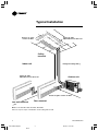
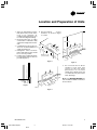
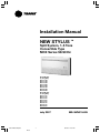
Installation Manual
NEW STYLUS
TM
Split System, 1-5 Tons
Convertible Type
MCX Series 50/60 Hz
50 Hz Models
Cooling Only
MCX 512 GB
MCX 518 GB
MCX 524 GB
MCX 530 GB
MCX 536 GB
MCX 042 GB
MCX 048 GB
MCX 060 GB
60 Hz Models
Cooling Only
MCX 512 G1
MCX 518 G1
MCX 524 G1
MCX 530 G1
MCX 536 G1
MCX 042 G1
MCX 048 G1
MCX 060 G1
July 2007
MS-SVN015-EN.p65
1
Black
MS-SVN015-EN
6/27/07, 11:23 AM
General Information
General Information
About the Unit
Caution
This Installation Manual is given as
a guide to good practice in the
installation by the installer of MCX
mini-split system. Installation
procedures should be performed in
the sequence that they appear in this
manual.
These MCX units are assembled,
pressure tested, dehydrated,
charged and run tested before
shipment. The information contained
in this manual applies to MCX units
are designed to operate in cooling
mode only and in cooling or heating
modes.
Cautions are provided at appropriate
places in this manual to indicate to
installers, operators, and service
personnel of potentially hazardous
situations which, if not avoided, MAY
result in minor or moderate injury or
malfunction of the unit.
For installing the unit to operate
properly and reliably, it must be
installed in accordance with these
instructions. Also, the services of a
qualified service technician should
be employed, through the
maintenance contract with a
reputable service company.
Read these Installation Instructions
completely before installing the air
conditioning system.
Trane MCX series of mini-split
systems offer three styles of
installation: floor, low wall and under
ceiling with both LCD wireless
remote control or wired control.
Trane MCX series provide flexibility
and savings.
Note: For model MCX 042, MCX 048
and MCX 060, there are only two
styles of installation: under ceiling
and low wall.
About this Manual
Reception
Cautions appear at appropriate
places in this Instruction Manual.
Your personal safety and the proper
operation of this machine require
that you follow them carefully.
The Trane Company assumes no
liability for installations or servicing
performed by unqualified personnel.
All phases of the installation of this
air conditioning system must
conform to all national, provincial,
state and local codes.
On arrival, inspect the unit before
signing the delivery note. Specify any
damage of the unit on the delivery
note, and send a registered letter of
protest to the last carrier of the
goods within 72 hours of delivery.
Notify the dealer at the same time.
The unit should be totally inspected
within 7 days of delivery. If any
concealed damage is discovered,
send a registered letter of protest to
the carrier within 7 days of delivery
and notify the dealer.
Warning
Warnings are provided at
appropriate places in this manual to
indicate to installers, operators and
service personnel of potentially
hazardous situations which, if not
avoided, COULD result in death or
serious injury.
© American Standard Inc. 2005
MS-SVN015-EN.p65
Warranty is based on the general
terms and conditions by country. The
warranty is void if the equipment is
modified or repaired without the
written approval of The Trane
Company, if the operating limits are
exceeded or if the control system or
the electrical wiring is modified.
Damage due to inappropriate
installation, lack of knowledge or
failure to comply with the
manufacturer’s instructions, is not
covered by the warranty obligation.
If the installation does not conform
to the rules described in Installation
Manual, it may entail cancellation of
warranty and liabilities by The Trane
Company.
Important
This document is customer property
and is to remain with unit. Please
place in service information pack
upon completion of work. These
instructions do not cover all
variations in systems, nor do they
provide for every possible
contingency to be met in connection
with installation. Should further
information be desired or should
particular problems arise which are
not covered sufficiently in this
manual, the matter should be
referred to your authorized Trane
dealer.
MS-SVN015-EN
2
Black
Warranty
6/27/07, 11:23 AM
Contents
General Information
Typical Installation
Location and Preparation of Units
Unit Installation
Connection of Refrigerant Tubing
Condensate Drain Piping
Electrical Installation
Remote Control Installation
Typical Wiring Diagram
Dimensional Data
Notes
MS-SVN015-EN
2
4
5
6
7
9
10
11
12
16
18
3
MS-SVN015-EN.p65
3
Black
6/27/07, 11:59 AM
Typical Installation
Return air grille
contains air filter
Supply air grille
Adjustable louvers direct air
Ceiling
mounted
Indoor unit
Refrigerant tubing/wiring
Supply air grille
Adjustable louvers direct air
Outdoor unit
Drain
Return air grille contains air filter
Low wall mounted
Floor mounted
Note: For models MCX 042, MCX 048, MCX 060
there are only two styles of installation: under ceiling and low wall
4
MS-SVN015-EN
MS-SVN015-EN.p65
4
Black
6/27/07, 11:23 AM
Location and Preparation of Units
1. Select an appropriate position
that allows every corners of the
room to be uniformly air
conditioned and where it is easy
to route the refrigerant tubing.
2. Ensure that the floor or ceiling
construction is sufficient to fully
support the weight of the indoor
unit.
3. Consideration must be given to
assure an unobstructed flow of
supply and return air.
4. Refrigerant tubes between
indoor and outdoor units should
be as short as possible.
5. Length of the condensate drain
hose should be kept as short as
possible (Figure 1).
6. Recommended
service
clearance as shown in figure
2, 3 and 4.
Min. 120 cm.
.
Min .
m
30 c
Min.
20 cm.
Mi
20 n.
cm
.
Min.
m.
20 c
Maintenance area
(Celling mounted)
Mi
30 n.
cm
.
Figure 2
a
are )
ce ted
nan moun
e
t
in
ll
Ma wa
w
(Lo
Min.
20 cm.
Figure 4
7. Do not install unit in direct
sunlight or near other heat
sources as this may affect
performance. Do not allow
outside air to directly enter unit
or condensate may form at the
unit’s discharge.
.
Min .
m
30 c
Min.
m.
20 c
Figure 1
a
are
ce d)
nan ounte
e
t
in
Ma loor m
(F
Note: For MCX042-MCX060 the
unit should be installed over the floor
at least 20 cm.
Figure 3
MS-SVN015-EN
5
MS-SVN015-EN.p65
5
Black
6/27/07, 11:23 AM
Unit Installation
6. Unscrew at the return grille
(Figure 7).
Indoor Unit
A
1. Select a location to route tubing,
wiring and drain pipe between
the indoor and outdoor units.
2. Make a hole in the wall using a
key hole saw or hole-cutting drill
attachment.
The hole should be made at a
slight downward slant to the
outdoor side (Figure 5).
8.5"(215)
0.83"(21)
B
0.83"(21)
Outdoor side
Figure 10
Figure 7
7. Unscrew at the grille bottom
hinges, pull out the screw, and
unscrew at the side panel front
(Figure 8). Then, push down on
the side panel front and pull up
(Figure 9).
Indoor side
Figure 5
Before cutting, check that no pipes
or studs are directly behind the
place to be cut. Avoid areas where
electrical wiring or conduits are
located.
3. Place the unit on a solid and level
foundation.
4. Tubing, wiring through and drain
pipe of low wall and floor
mounted units can be routed,
rear or right side of unit when
facing front.
Ceiling mounted can be routed
straight downward.
5. Pull air filters upward (Figure 6).
Note: = A 0.49" x 1.575" - 4 SLOT
(Mounting hole) (12.5 mm 40.0 mm)
Unit Size
MCX 512-518
MCX 524
MCX 530-536
MCX 042-048
MCX 060
B
36.2" (920)
46.1" (1,170)
55.9" (1,420)
65.7" (1,670)
75.6" (1,920)
8. Place or hang the unit at the
selected position.
9. Replace both right and left side
panels, and the return grille after
the installation of wiring, tubing
and piping is complete.
Figure 8
Outdoor Unit
See the proper installation method
provided in the Installation Manual
for the outdoor unit.
Pull
Pull
Figure 9
Figure 6
6
MS-SVN015-EN
MS-SVN015-EN.p65
6
Black
6/27/07, 11:23 AM
Connection of Refrigerant Tubing
The indoor unit refrigerant line
connections are flared both 50 Hz
and 60 Hz. Installation brazing, leak
testing, and evacuation of refrigerant
lines are covered in the Installer
Manual, packaged with the outdoor
unit. Read the instructions before
installing the refrigerant lines.
When reaming, hold the tube end
downward and be sure that no
copper scraps fall into the tube.
3. Remove the flare nut from the
unit and be sure to mount it on
the copper tube.
After
Figure 13
4. Make a flare at the end of copper
tube with a flare tool (Figure
14, 15).
Flare nut
Figure 11
5. When bending the tube, be
careful not to crush it. To prevent
crushing of the tube, bend it
gently and do not bend the tube
at a radius curvature of less than
100 mm.
6. If the copper tube is bent or
pulled too often, it will become
stiff. Do not bend the pipe more
than three times at one place.
Cautions before
connecting tubes tightly
Connecting the unit with flaring
procedure.
(Only for MCX 512-536)
Copper
tubing
Flare tool
Figure 14
7. Be sure to apply a sealing cap or
water-proof tape to prevent dust
or water from getting into the
tubes before they are used.
8. Be sure to apply refrigerant
lubricant to the matching
surfaces of the flare and union
before connecting them
together. This is effective for
reducing gas leaks (Figure 16).
L
2. Hold each pipe downward when
cutting and remove burrs at the
end of the copper tube with a
tube reamer or file. This process
is important and should be done
carefully to make a good flare
(Figure 12 and Figure 13).
Check if (L) is flared uniform
and is not cracked or scratched.
L Dimension:
1.4 to 1.7 mm (6.35 mm dia)
1.8 to 2.0 mm (9.53 mm dia)
1.9 to 2.2 mm (12.7 mm dia)
2.1 to 2.4 mm (15.88 mm dia)
Reamer
Inside surface is glossy and
smooth.
Edge is smooth.
Tapered sides are of uniform
length.
Bending
Before
Copper
tubing
-
Deburring
The indoor unit refrigerant piping
connections are located on the right
hand side when facing the unit
(Figure 11).
1. Flaring (If piping is procured or
cut at the site). Cut the copper
tube to the required length with
a tube cutter. It is recommended
to cut approx. 30-50 cm. longer
than the tubing length you
estimate.
A good flare should have the
following characteristics:
Apply refrigerant
lubricant here
Figure 16
Figure 12
Figure 15
MS-SVN015-EN
7
MS-SVN015-EN.p65
7
Black
6/27/07, 11:23 AM
Connection of Refrigerant Tubing
Connection
Connecting the unit with
brazing procedure
(Only for MCX 042-060)
9. For proper connection, align the
union tube and flare tube straight
with each other, then screw in the
flare nut lightly at first to obtain a
smooth match (Figure 17).
Union
1. Cut the copper tube to the
required length with a tube cutter.
It is recommended to cut approx.
20-30 cm. longer than the tube
length you estimate.
2. Remove burrs at the end of the
copper tube with a tube reamer
(Figure 12).
3. There are 2 ways to connect the
copper tube
- Use a coupling between the
copper tube of indoor unit and
the copper tube used for
installation (Figure 19).
Flare nut
Figure 17
10. Tighten the flare nut to the
specified tightening torque with
torque wrench and adjustable
wrench (Figure 18).
Torch
Copper tube
of indoor unit
Solder coupling
Flare Nut Tightening Torque
Flare Nut/Piping Size Tightening
kgf, - cm
5. Insulate the entire gas line.
6. Do not allow uninsulated liquid
line to come in direct contact
with bare gas line.
7. Precautions should be taken to
avoid heat damage to the
pressure tap valve core during
brazing. It is recommended that
a wet rag be wrapped around the
valve body.
8. It is recommended to use braze
shield, soak pad in water and
place over suction and liquid
lines to protect unit finish.
9. To braze the copper tube, before
brazing a copper tube to a solder
coupling or a copper tube to an
expanded tube, do not forget to
keep them tight as shown in
Figure 21, 22.
CO
MM
ET
Copper tube
from indoor
unit
3
Solder rod
Solder
coupling
Torque
lbf-in
Copper tube from
outdoor unit
Copper tube of
outdoor unit
6.35 mm (1/4") dia. 150~200 130~170
9.53 mm (3/8") dia. 350~400 300~340
Figure 21
Figure 19
12.7 mm (1/2") dia. 500~550 430~470
- Expand the copper tube by
using a swaging tool set as in
Figure 20.
15.88 mm (5/8") dia. 600~650 520~570
Swaging
tool
Torch
CO
MM
ET
Copper tube
from indoor
unit
3
Solder rod
Solder
coupling
Copper tube from
outdoor unit
Wrench
(adjustable)
Indoor unit
pipe
Torque
wrench
Tube holder
(Clamp)
Copper
tube
Connection pipe
Flare nut
Figure 18
Figure 20
11. Repeat the process above for the
remaining line.
4. Clean internal and external surfaces
of coupling or expanded tube prior
to brazing.
8
Figure 22
10. Use a dry nitrogen purge and
brazing alloy without flux when
brazing the field line to the
copper factory connection. Flow
dry nitrogen into either valve
pressure tap port, through the
tubing and out the other port
while brazing.
11. Braze using accepted good
brazing techniques.
MS-SVN015-EN
MS-SVN015-EN.p65
8
Black
6/27/07, 11:23 AM
Condensate Drain Piping
-
The drain hose should run
straight down the wall to a
level where the runoff will not
stain the wall.
-
There should be no traps.
Avoid putting the end of the
hose in water.
-
To conveniently drain the
system, the drain hose must
slant downward, with a slope
of at least 1 : 50 to prevent
leakage. Figure 23 shows the
unit in the floor mounted
position.
-
When the drain hose is placed
in the room, insulate the hose
with foam polyethylene to
avoid damage to the ceiling or
furniture.
-
After completing installation of
refrigerant lines, wiring and
drain connections, bind the
tubing, wiring and drain hose
(check if local codes permit
binding) into a bundle by using
tape at 100 or 200 mm (4" to
8") intervals. Make sure the
drain hose is at the bottom of
the bundle (Figure 24).
Indoor unit
Slant
Drain hose
Figure 24
Drain hose
Figure 23
MS-SVN015-EN
9
MS-SVN015-EN.p65
9
Black
6/27/07, 11:24 AM
Electrical Installation
All wiring and grounding must
comply with local electrical codes.
1. Wiring
Important Safeguards:
- Check the unit nameplate
for electrical rating.
Be sure wiring is done
according to local codes
and wiring diagram.
- Use a separate power line
with circuit breaker for each
air conditioning unit.
- Connect electrical ground
to all units.
- Wiring should not touch
refrigerant
tubing,
compressor, motors or
moving parts.
- The manufacturer will
accept no responsibility for
problems caused by
unauthorized changes in
the internal wiring.
- Connect the wiring firmly.
2. Electrical Connections
See Section: Wiring System
Diagram
Indoor Unit
Remove the right side panel and
return grille (see previous
instructions), to access the terminal
base.
- Pass the system wiring
through the PVC pipe (both
power and control lines) to
interconnect indoor and
outdoor units.
- Connect the wire terminals to
the terminal base (see
connection indication on
system wiring diagram).
- Make sure all connections are
tight.
Outdoor unit
Outdoor Unit - Indoor Unit Electrical
Interconnection should be in
accordance with the applicable
system wiring diagram and indoor
unit diagrams.
Outdoor unit diagram are contained
in the outdoor unit Installer Manual.
Note:
-
10
All wiring must comply with
national state and local codes.
After
completing
the
connections, re-confirm them
to be in accordance with the
unit and system wiring
diagrams.
MS-SVN015-EN
MS-SVN015-EN.p65
10
Black
6/27/07, 11:24 AM
Remote Control Installation
Locate and attach the
wireless remote control
and wired control as
follows:
1. Do not place the control and
the remote control near heat
sources or expose to the
direct rays of the sun.
2. Do not expose the control to
the indoor unit’s supply air
stream.
3. Do not place in a confined
space.
4. Attach the remote control
holder as shown in Figure 25,
26.
90.0
61.0
14.5
90.0
45.0
14.5
ECON
45.0
4.0 X 2
SLOT
O
FAN
ON COOL
DRY
OFF HEAT
POWE
AUTO
RCOO
L Z
SW
Dimension
Z
MO
DE
LO
ON
UVE
R
SW
EE
P
FR
BLAONT
DE
POW
ER
COOL
OFF
ECON
O
SLEE
P
LIG
HT
SEND
ON
SW
SL
OF
AU
TO
F
EC
EE
ON
P
O
EC
TU
O
RB
ON NO
O
TU
OF RB
F O
TE
MP
ME
NU
MO
DE
FA
N
Wireless Remote Control
Remote Control
Figure 25
Mounting Bracket
Figure 26
MS-SVN015-EN
11
MS-SVN015-EN.p65
11
Black
6/27/07, 11:24 AM
Typical Wiring Diagram
MCX512-536GB (50 Hz)
MCX512-536G1 (60 Hz)
INDOOR UNIT, COOLING ONLY WITH CONTROL TYPE “R”, 4 SPEED
1. FREEZE SENSOR
LOCATED ON
EVAPORATOR COIL
2. TEMPERATURE
SENSOR LOCATED
IN RETURN AIR
STREAM
1
2
GRN/YL
ROOM
STEPPER TOP
P22
P21
FREEZE
P26
DISPLAY
P20
SWEEP MOTOR
(OPTION)
P17
P16
P7
J2
J1
BLK
MED
LOW
P6
YL
RED
HI
P5
BLU
RED
LINE-C
EX-HI
P4
BLK
LINE
P3
RED
NEUTRAL
P1
P2
WHT
RED
P19
STEPPER FRONT
INFRARED RECEIVER
YL
BLU
N C1 C2
BLK
L
WHT
WIRELESS REMOTE
CONTROLLER
RED
WHT
GRN/YL
WIRING TO
GROUNDING SYSTEM
BRW
POWER SUPPLY
220-240VAC/1PH/50Hz
220-240VAC/1PH/60Hz
BLOWER
MOTOR
200-240 VAC CONTROL
WIRING TO OUTDOOR UNIT
DESCRIPTION
COLOR CODE
FIELD WIRING
FACTORY WIRING
COIL
JUNCTION
TERMINAL BOARD
BLU
BLK
RED
WHT
GRN
YL
BR
BLUE
BLACK
RED
WHITE
GREEN
YELLOW
BROWN
CAPACITOR
FUSE 3 AMP.
12
MS-SVN015-EN
MS-SVN015-EN.p65
12
Black
6/27/07, 11:24 AM
Typical Wiring Diagram
MCX042-060GB (50 Hz)
MCX042-060G1 (60 Hz)
INDOOR UNIT, COOLING ONLY WITH CONTROL TYPE “R”, 3 SPEED
1. FREEZE SENSOR
LOCATED ON
EVAPORATOR COIL
2. TEMPERATURE
SENSOR LOCATED
IN RETURN AIR
STREAM
1
2
GRN/YL
P16
P6
J2
J1
BLK
RED
MED
LOW
P5
BLU
RED
LINE-C
HI
P4
BLK
LINE
P3
RED
NEUTRAL
P1
P2
WHT
RED
INFRARED RECEIVER
ROOM
P17
P22
P21
FREEZE
P26
DISPLAY
BLK
N C1 C2
BLU
L
WHT
WIRELESS REMOTE
CONTROLLER
RED
WHT
GRN/YL
WIRING TO
GROUNDING SYSTEM
BRW
POWER SUPPLY
220-240VAC/1PH/50Hz
220-240VAC/1PH/60Hz
BLOWER
MOTOR
200-240 VAC CONTROL
WIRING TO OUTDOOR UNIT
DESCRIPTION
COLOR CODE
FIELD WIRING
FACTORY WIRING
COIL
JUNCTION
TERMINAL BOARD
BLU
BLK
RED
WHT
GRN
YL
BR
BLUE
BLACK
RED
WHITE
GREEN
YELLOW
BROWN
CAPACITOR
FUSE 3 AMP.
MS-SVN015-EN
13
MS-SVN015-EN.p65
13
Black
6/27/07, 11:24 AM
Typical Wiring Diagram
MCX512-536GB (50 Hz)
MCX512-536G1 (60 Hz)
INDOOR UNIT, COOLING ONLY WITH CONTROL TYPE “W”, 4 SPEED
1. FREEZE SENSOR
LOCATED ON
EVAPORATOR COIL
2. TEMPERATURE
SENSOR LOCATED
IN RETURN AIR
STREAM
1
2
GRN/YL
P21
FREEZE
DISPLAY
ROOM
STEPPER TOP
P22
P31
P20
SWEEP MOTOR
(OPTION)
P17
P16
P7
J2
J1
BLK
MED
LOW
P6
YL
RED
HI
P5
BLU
RED
LINE-C
EX-HI
P4
BLK
LINE
P3
RED
NEUTRAL
P1
P2
WHT
RED
P19
STEPPER FRONT
WIRE DISPLAY
YL
BLU
BLK
N C1 C2
WHT
L
RED
WHT
GRN/YL
WIRING TO
GROUNDING SYSTEM
BRW
POWER SUPPLY
220-240VAC/1PH/50Hz
220-240VAC/1PH/60Hz
BLOWER
MOTOR
200-240 VAC CONTROL
WIRING TO OUTDOOR UNIT
DESCRIPTION
COLOR CODE
FIELD WIRING
FACTORY WIRING
COIL
JUNCTION
TERMINAL BOARD
BLU
BLK
RED
WHT
GRN
YL
BR
BLUE
BLACK
RED
WHITE
GREEN
YELLOW
BROWN
CAPACITOR
FUSE 3 AMP.
14
MS-SVN015-EN
MS-SVN015-EN.p65
14
Black
6/27/07, 11:24 AM
Typical Wiring Diagram
MCX042-060GB (50 Hz)
MCX042-060G1 (60 Hz)
INDOOR UNIT, COOLING ONLY WITH CONTROL TYPE “W”, 3 SPEED
1. FREEZE SENSOR
LOCATED ON
EVAPORATOR COIL
2. TEMPERATURE
SENSOR LOCATED
IN RETURN AIR
STREAM
1
2
GRN/YL
P21
P31
P16
LOW
P6
RED
J2
J1
BLK
MED
P5
BLU
RED
LINE-C
HI
P4
BLK
LINE
P3
RED
NEUTRAL
P1
P2
WHT
RED
WIRE DISPLAY
ROOM
P17
P22
FREEZE
DISPLAY
GRN/YL
BLU
WHT
BLK
N C1 C2
RED
L
WHT
WIRING TO
GROUNDING SYSTEM
BRW
POWER SUPPLY
220-240VAC/1PH/50Hz
220-240VAC/1PH/60Hz
BLOWER
MOTOR
200-240 VAC CONTROL
WIRING TO OUTDOOR UNIT
DESCRIPTION
COLOR CODE
FIELD WIRING
FACTORY WIRING
COIL
JUNCTION
TERMINAL BOARD
BLU
BLK
RED
WHT
GRN
YL
BR
BLUE
BLACK
RED
WHITE
GREEN
YELLOW
BROWN
CAPACITOR
FUSE 3 AMP.
MS-SVN015-EN
15
MS-SVN015-EN.p65
15
Black
6/27/07, 11:24 AM
Dimensional Data
OUTLINE DIMENSIONS
MCX512-536GB (EXPORT 50 Hz)
MCX512-536G1 (EXPORT 60 Hz)
DIMENSIONAL DATA
CONN. SIZES
A
TYPE
B
C
MODEL
LIQUID
SUCTION
CONNECTIONS.
MCX512GB/G1
MCX518GB/G1
1/4 (6.4)
1/2 (12.7)
FLARED
42.28
(1074.0)
MCX524GB/G1
3/8 (9.5)
5/8 (15.9)
FLARED
51.13
MCX530GB/G1
3/8 (9.5)
5/8 (15.9)
FLARED
MCX536GB/G1
3/8 (9.5)
3/4 (19.0)
FLARED
NOTE
IN.
(MM.)
IN.
(MM.)
EACH
34.61
(879.0)
4
(1324.0)
44.45
(1129.0)
4
61.97
(1574.0)
54.29
(1379.0)
6
61.97
(1574.0)
54.29
(1379.0)
6
1) SUCTION AND LIQUID LINES HAVE FLARE TYPE CONNECTIONS.
2) DIMENSIONS : MILIMETERS [INCHES] 25.4 MM. = 1 IN.
16
MS-SVN015-EN
MS-SVN015-EN.p65
16
Black
6/27/07, 11:24 AM
Dimensional Data
OUTLINE DIMENSIONS
MCX042-060GB (EXPORT 50 Hz)
MCX042-060G1 (EXPORT 60 Hz)
DIMENSIONAL DATA
CONN. SIZES
TYPE
A
B
C
D
MODEL
LIQUID
SUCTION
CONNECTIONS.
MCX042GB/G1
MCX048GB/G1
3/8 (9.5)
3/8 (9.5)
7/8
(22.2)
1-1/8 (28.6)
BRAZED
BRAZED
71.81
(1824.0)
64.13
(1629.0)
8
15.76
(400)
MCX060GB/G1
3/8 (9.5)
1-1/8 (28.6)
BRAZED
81.65
(2074.0)
73.98
(1879.0)
8
23.64
(600)
NOTE
IN.
(MM.)
1) DIMENSIONS : MILIMETERS [INCHES]
IN.
(MM.)
EACH
IN.
(MM.)
25.4 MM. = 1 IN.
MS-SVN015-EN
17
MS-SVN015-EN.p65
17
Black
6/27/07, 11:24 AM
Notes
18
MS-SVN015-EN
MS-SVN015-EN.p65
18
Black
6/27/07, 11:24 AM
Notes
MS-SVN015-EN
19
MS-SVN015-EN.p65
19
Black
6/27/07, 11:24 AM
Trane
A business of American Standard Companies
www.trane.com
For more information, contact your local district
office
MS-SVN015-EN.p65
Literature Order Number:
MS-SVN015-EN
Date:
Jul 2007
Supersedes:
Oct 2002
Stocking Location:
Bangkok, Thailand
Trane has a policy of continuous product and product data improvement and reserves the right to
change design and specific ations without notice. Only qualified technicians should perform the installation
and servicing of equipment referred to in this publication.
20
Black
7/18/07, 11:06 AM