1
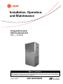
Installation, Operation, and Maintenance Integral Air-Cooled Self-Contained Unit SCIJ — R-410A SAFETY WARNING Only qualified personnel should install and service the equipment. The installation, starting up, and servicing of heating, ventilating, and airconditioning equipment can be hazardous and requires specific knowledge and training. Improperly installed, adjusted or altered equipment by an unqualified person could result in death or serious injury. When working on the equipment, observe all precautions in the literature and on the tags, stickers, and labels that are attached to the equipment. January 2014 SXIJ-SVX01B-EN Warnings, Cautions and Notices Warnings, Cautions and Notices. Note that warnings, cautions and notices appear at appropriate intervals throughout this manual. Warnings are provided to alert installing contractors to potential hazards that could result in death or personal injury. Cautions are designed to alert personnel to hazardous situations that could result in personal injury, while notices indicate a situation that could result in equipment or property-damage-only accidents. Your personal safety and the proper operation of this machine depend upon the strict observance of these precautions. Read this manual thoroughly before operating or servicing this unit. municipalities may have additional requirements that must also be adhered to for responsible management of refrigerants. Know the applicable laws and follow them. WARNING Proper Field Wiring and Grounding Required! All field wiring MUST be performed by qualified personnel. Improperly installed and grounded field wiring poses FIRE and ELECTROCUTION hazards. To avoid these hazards, you MUST follow requirements for field wiring installation and grounding as described in NEC and your local/state electrical codes. Failure to follow code could result in death or serious injury. ATTENTION: Warnings, Cautions, and Notices appear at appropriate sections throughout this literature. Read these carefully: Indicates a potentially hazardous situation which, if not avoided, could result in death or serious injury. Indicates a potentially hazardous CAUTIONs situation which, if not avoided, could result in minor or moderate injury. It could also be used to alert against unsafe practices. a situation that could result in NOTICE: Indicates equipment or property-damage only accidents. WARNING WARNING Personal Protective Equipment (PPE) Required! Installing/servicing this unit could result in exposure to electrical, mechanical and chemical hazards. • Before installing/servicing this unit, technicians MUST put on all Personal Protective Equipment (PPE) recommended for the work being undertaken. ALWAYS refer to appropriate MSDS sheets and OSHA guidelines for proper PPE. • When working with or around hazardous chemicals, ALWAYS refer to the appropriate MSDS sheets and OSHA guidelines for information on allowable personal exposure levels, proper respiratory protection and handling recommendations. • If there is a risk of arc or flash, technicians MUST put on all Personal Protective Equipment (PPE) in accordance with NFPA 70E or other country-specific requirements for arc flash protection, PRIOR to servicing the unit. Important Environmental Concerns! Scientific research has shown that certain man-made chemicals can affect the earth’s naturally occurring stratospheric ozone layer when released to the atmosphere. In particular, several of the identified chemicals that may affect the ozone layer are refrigerants that contain Chlorine, Fluorine and Carbon (CFCs) and those containing Hydrogen, Chlorine, Fluorine and Carbon (HCFCs). Not all refrigerants containing these compounds have the same potential impact to the environment.Trane advocates the responsible handling of all refrigerants-including industry replacements for CFCs such as HCFCs and HFCs. Failure to follow recommendations could result in death or serious injury. Responsible Refrigerant Practices! Trane believes that responsible refrigerant practices are important to the environment, our customers, and the air conditioning industry. All technicians who handle refrigerants must be certified.The Federal Clean Air Act (Section 608) sets forth the requirements for handling, reclaiming, recovering and recycling of certain refrigerants and the equipment that is used in these service procedures. In addition, some states or © 2014Trane All rights reserved SXIJ-SVX01B-EN Warnings, Cautions and Notices Introduction Overview of Manual This booklet describes proper installation, start-up, operation, and maintenance procedures for the Integral Air-Cooled unit, model SCIJ (with Micro-Channel Condensers). Carefully review the information within this manual and follow the instructions to minimize the risk of improper operation and/or component damage. Note: One copy of the appropriate service literature ships inside the control panel of each unit. Note: This document is customer property and must be retained by the unit's owner for use by maintenance personnel. It is important that you perform periodic maintenance to help ensure trouble free operation. Should equipment failure occur, contact a qualifiedTrane service organization for an experienced HVAC technician to properly diagnose and repair this equipment. Unit Nameplate The unit nameplate identifies the unit model number, appropriate service literature, and wiring diagram numbers. It is mounted on the control panel door. Reference this information when making inquires or ordering parts or literature. Revision Summary Use this manual for Integral Air-Cooled units, model SCIJ (with Micro-Channel condensers). SXIJ-SVX01B-EN (30 Jan 2014) Removed coil resistant coating option from model number description. SXIJ-SVX01B-EN (17 Apr 2012) Modifications for 2-speed motor. SXIJ-SVX01A-EN This manual supersedes SXIH-SVX01C-EN (October 2008). Trademarks Trane and theTrane logo are trademarks ofTrane in the United States and other countries. All trademarks referenced in this document are the trademarks of their respective owners. SXIJ-SVX01B-EN 3 Table of Contents Warnings, Cautions and Notices . . . . . . . . . . 2 Introduction . . . . . . . . . . . . . . . . . . . . . . . . . . . 3 Overview of Manual . . . . . . . . . . . . . . . . . . 3 Unit Nameplate . . . . . . . . . . . . . . . . . . . . . 3 Revision History . . . . . . . . . . . . . . . . . . . . . 3 Trademarks . . . . . . . . . . . . . . . . . . . . . . . . . 3 Model Number Description . . . . . . . . . . . . . . . 5 General Information . . . . . . . . . . . . . . . . . . . . . 6 Commonly Used Acronyms . . . . . . . . . . . . . 6 Refrigeration Circuits . . . . . . . . . . . . . . . . . . . 6 Evaporator Section . . . . . . . . . . . . . . . . . . . . 6 Controls . . . . . . . . . . . . . . . . . . . . . . . . . . . . . . 6 Field Installed Accessories . . . . . . . . . . . . . . 6 Installation . . . . . . . . . . . . . . . . . . . . . . . . . . . . . . 7 Pre-Installation Considerations . . . . . . . . . . 7 Checklist . . . . . . . . . . . . . . . . . . . . . . . . . . . 7 Receiving and Handling . . . . . . . . . . . . . . . 7 Acoustic Considerations . . . . . . . . . . . . . . 7 Installation Preparation . . . . . . . . . . . . . . . 8 Dimensions and Weights . . . . . . . . . . . . . . . 8 Mechanical Requirements . . . . . . . . . . . . . 11 Electrical Requirements . . . . . . . . . . . . . . . 12 Voltage Imbalance . . . . . . . . . . . . . . . . . . 12 Installation Checklist . . . . . . . . . . . . . . . . . . 14 Fan Discharge Conversion Procedure . . 14 Low Ambient Control Kit Installation . . . 15 Hydronic Coil Installation . . . . . . . . . . . . . 15 Plenum Installation . . . . . . . . . . . . . . . . . 16 Pre-Startup Checklist . . . . . . . . . . . . . . . . . . 17 Unit Startup Procedures . . . . . . . . . . . . . . . 17 Operation . . . . . . . . . . . . . . . . . . . . . . . . . . . . . . 18 Sequence of Operation . . . . . . . . . . . . . . 18 Maintenance . . . . . . . . . . . . . . . . . . . . . . . . . . . 19 Maintenance Procedures . . . . . . . . . . . . . . 19 Cleaning the Condenser Coils . . . . . . . . 20 Periodic Checklists . . . . . . . . . . . . . . . . . . 21 Troubleshooting . . . . . . . . . . . . . . . . . . . . . . 22 4 SXIJ-SVX01B-EN Model Number Description Digit 1 - Unit Model S = self contained Digit 2 - Unit Type C = commercial Digit 3 - Condenser Medium I = integral air-cooled Digit 4 - Development Sequence J = development series Digit 5, 6, 7- Unit Nominal Capacity 050 075 100 150 = 5 tons = 7.5 tons = 10 tons = 15 tons Digit 8 - Unit Voltage 3 = 208 - 230 volt/60 hz/3 ph 4 = 460 volt/60 hz/3 ph 5 = 575 volt/60 hz/3 ph Digit 9 - Air Flow Configuration 1 = horizontal discharge/rear return 2 = vertical discharge/front return 3 = vertical discharge/rear return Digit 10, 11 - Design Sequence **= factory assigned Digit 12 - Air Filter Type 1 = one-inch fiberglass throwaway Digit 13 - Control 0 = control interface Digit 14 - Unit Finish 1 = painted Digit 15 - Coil Finish 0 C E H = = = = none condenser coated evaporator coated condenser + evaporator coated SXIJ-SVX01B-EN 5 General Information The integral air-cooled unit, model SCIJ with MicroChannel Condenser, is a high efficiency, vertical air cooled air conditioner. Units have either front or top discharge configuration options and easy service access. Unit construction is heavy gage steel with a baked enamel finish. Available unit voltages are 208/3/60, 230/3/60, and 460/3/60, 575/3/60. fixed diameter blower pulley.The condenser fan section consists of one, two or three forward curved centrifugal fans powered by a premium efficiency motor through an adjustable motor sheave and fixed diameter blower pulley. Condenser motor belt tension is adjusted by an adjustable motor mounting base. Control box access is from the front of the unit to ease electrical hook-up. Commonly Used Acronyms Controls For convenience, a number of acronyms and abbreviations are used throughout this manual.These acronyms are alphabetically listed and defined below. The standard control panel consists of a high voltage terminal block, overload relays for each fan motor, transformer, 3-pole 24 volt contactors for each motor and compressor, and a 5-second delay timer. Remote thermostat controls are field-installed. cfm = cubic-feet-per-minute CKT = circuit CV = constant volume CW = clockwise CCW = counterclockwise E/A = exhaust air F/A = fresh air IOM= installation/operation/maintenance manual LH = left-hand O/A = outside air psig = pounds-per-square-inch, gauge pressure R/A = return air RH = right-hand Field Installed Accessories These items ship separately for field installation: • steam coil • hot water coil • plenum • low ambient kit • oversized or s-speed motors • remote thermostat Note: Application of the above options and/or accessories may require field adjustment of fan speeds to ensure proper airflow and performance. RPM = revolutions-per-minute S/A = supply air SZ = single-zone (unit airflow) VAV = variable air volume Note: Cross-reference to related publication: Internal AirCooled Self-Contained Product Catalog: PKGPRC019-EN. Refrigeration Circuits Units are configured in single or double refrigeration circuits. Each circuit consists of a: • high efficiency scroll compressor mounted on rubber isolation grommets • condenser and evaporator coils, designed for optimum performance and efficiency with lanced fins and rifled tubing • filter-drier Evaporator Section The evaporator fan section consists of one, two or three forward curved centrifugal fans powered by a premium efficiency motor through an adjustable motor sheave, and 6 SXIJ-SVX01B-EN Installation Pre-Installation Considerations • Checklist The following checklist gives an overview of the recommended pre-installation considerations. Follow the procedures in this section to ensure installation is complete and adequate for proper unit operation. Verify this checklist is complete before beginning unit installation. Report concealed damage to the freight line within the allotted time after delivery. Verify with the carrier their allotted time to submit a claim. Note: Failure to follow these procedures may result in no reimbursement for damages from the freight company. • Do not move damaged material from the receiving location. It is the receiver's responsibility to provide reasonable evidence that concealed damage did not occur after delivery. • Verify the unit size and tagging with the unit nameplate to ensure the correct unit is received. • • Inspect the unit for possible shipping damage and make any necessary claims with the freight delivery company immediately. Do not continue unpacking the shipment if it appears damaged. Retain all packaging.Take photos of damaged material if possible. • Notify the carrier's terminal of the damage immediately by phone and mail. Request an immediate joint inspection of the damage by the carrier and consignee. • Notify yourTrane representative of the damage and arrange for repair. Have the carrier inspect the damage before making any repairs to the unit. • Before installing the unit, remember to allow minimum recommended clearances for routine maintenance and service. Refer to unit dimensions and clearances on submittals or in the “Dimensions and Weights,” p. 8section. • Verify the unit is configured properly prior to beginning unit installation. • Make proper acoustic considerations before installing unit. Do not install unit near sound-sensitive locations. • Allow adequate space for service and operating clearances. Reference “ServiceAccess,” p. 7 section on this page. • Make provisions for correct supply power and note electrical connection knockouts locations on the unit submittals or in the “Dimensions and Weights,” p. 8 section. • Ensure the unit installation location is level. Receiving and Handling Shipping Package Integral air-cooled units ship assembled on skids. Units ship in the unitary configuration, assembled, piped, and charged with refrigerant. Unit Storage Take precautions to prevent condensate from forming inside the unit's electrical compartments and motors if the unit is stored before it is installed. Service Access Maintain adequate clearances around and above the unit to ensure proper unit operation and allow sufficient service access.Trane recommends 36-inches service access on all sides of the unit. WARNING Hazardous Voltage! Disconnect all electric power, including remote disconnects before servicing. Follow proper lockout/ tagout procedures to ensure the power can not be inadvertently energized. Failure to disconnect power before servicing could result in death or serious injury. Receiving Checklist Acoustic Considerations Complete the following checklist immediately after receiving unit shipment to detect possible shipping damage. Before determining the final unit installation site, remember that proper unit placement is critical in reducing transmitting sound levels to the building.The ideal time to make provisions to reduce sound transmissions is during the design phase.The most economical means of avoiding a potential acoustical problem is to place units in areas that are not acoustically sensitive. • Verify that the unit nameplate data corresponds to the sales order and bill of lading (including electrical data). • Visually inspect the unit exterior for physical signs of shipping damage or material shortages. • If a unit appears damaged, inspect it immediately before accepting the shipment. Remove access panels and check for interior component damage. Make specific notations concerning the damage on the freight bill. Do not refuse delivery. SXIJ-SVX01B-EN 7 Installation Unit Location Install the unit in a dry, indoor area between 50 and 115°F. Choose a location where sound levels, airflow and vibration, commonly associated with heavy-duty commercial equipment, will not be objectionable to occupants. In multiple unit installations, separate the individual units and stagger their location from floor to floor so as not to starve units for air and not to discharge warm condenser air from one condenser into the intake of another condenser. Place thermostats, air supplies and returns so that the individual unit will operate within its zone. Dimensions and Weights Table 1. Unit dimensions (with Micro-channel condenser coil), in-lbs. Unit Size (tons) A 5 Weights B C D E Ship Operating 56.69 20.63 20.63 18.92 18.92 945 856 7.5 — — — — — 1342 1210 10 — — — — — 1474 1342 15 — — — — — 2077 1923 Note: 7.5-ton and 10-ton in Figure 2, p. 9, 15-ton in Figure 3, p. 9 Installation Preparation 5-ton unit B A 15.43 C 24.90 1. Verify the installation location is level.To ensure proper unit operation, install the unit level (zero tolerance) in both horizontal axes. Failure to level the unit properly can result in condensate management problems, such as standing water inside the unit. Standing water and wet surfaces inside units can result in microbial growth (mold) in the drain pan that may cause unpleasant odors and serious health-related indoor air quality problem. Figure 1. 31.50 74.80 Before installing the unit, perform the following procedures to ensure proper unit operation. 13.64 2.74 SUPPLY AIR 2. Allow adequate service and code clearances as recommended in the “Service Access,” p. 7 section. SIDE ACCESS Unit Placement Install the unit on a firm, level surface. SUPPLY AIR RETURN AIR 3. Position the unit in its final location. FORKLIFT ACCESS 2.76 CONDENSER DISCHARGE front view Installing Optional Accessories Before installing ductwork, install accessories on unit. 18.86 E CONDENSER RETURN SIDE ACCESS 0.75 24.90 D 34.25 74.80 side view CONDENSER COIL 2.76 back view 8 SXIJ-SVX01B-EN Installation Figure 2. 7.5 and 10-ton unit 15.20 85.83 10.03 15-ton unit 114,00 15.20 24,00 15,50 10,00 15,50 10,00 15,50 24.90 22.70 Figure 3. CONTROLS ACCESS COMPRESSOR ACCESS GR IL L 75,00 74.80 25,00 GRILL COMPRESSOR ACCESS COMPRESSOR ACCESS CONTROLS ACCESS FORKLIFT ACCESS 2.68 18.86 14.77 18.86 3,00 front view 16.67 FORKLIFT ACESS front view 19,50 14,50 19,50 14,50 19,50 CONDENSER COIL 34,50 34.25 CONDENSER COIL 0,50 0.75 13,50 back view 31.50 13.64 SUPPLY AIR 2.74 back view SUPPLY AIR RETURN AIR 31,50 SIDE ACCESS 13,50 2,50 SUPPLY AIR CONDENSER DISCHARGE RETURN AIR CONDENSER RETURN SIDE ACCESS SIDE ACCESS SUPPLY AIR CONDENSER DISCHARGE side view CONDENSER RETURN SIDE ACCESS side view SXIJ-SVX01B-EN 9 Installation Figure 4. Component overview Figure 6. Hot water coil 3.239 vent OD CONNECTION inlet OD CONNECTION filter frame Figure 5. Plenum B A Table 3. Unit Size (tons) B A Table 2. Unit Size (tons) C Weight A B Wet Coil Dry Coil 50 5 52 ½ 47 1/16 63 7.5 & 10 81 5/ 76 ¼ 96 75 15 109 ¼ 104 ¼ 137 108 Notes: 1. Coils are field installed 2. Coil connections are mirror-image and can be mounted with either left or right hand connections. Plenum dimensions & weight, in-lbs. A B C Grill Size (W x H) Weight 5 56 ¾ 16 ¼ 31 ½ 52 ¾ x 12 ¾ 95 7.5 & 10 85 7/8 16 ¼ 31 ½ 81 ¾ x 12 ¾ 141 15 114 16 ¼ 31 ½ 110 x 12 ¾ 188 10 Hot water coil dimensions & weight, in-lbs. SXIJ-SVX01B-EN Installation Mechanical Requirements Figure 7. Steam coil Ductwork Considerations Install all air ducts according to the National Fire Protection Association standards for the "Installation of Air Conditioning and Ventilation Systems other than ResidenceType (NFPA 90A) and ResidenceType Warm Air Heating and Air Conditioning Systems (NFPA 90B). Make duct connections with a flexible material such as heavy canvas. If a fire hazard exists,Trane recommends using Flexweave 1000, type FW30 or equivalent canvas. Use three inches for the return duct and three inches for the discharge duct. Keep the material loose to absorb unit vibration. Run the ductwork as far as possible without changing size or direction. Do not make abrupt turns or transitions near the unit due to increased noise and excessive static losses. Use elbows with splitters or turning vanes to minimize static losses. Poorly constructed turning vanes may cause airflow generated noise. Check total external static pressures against fan characteristics to be sure the required airflow is available throughout the ductwork. Direct louvers up and down for condensers air discharge and intake so as to not short circuit condenser air. Pitch outdoor ducts away from unit to protect unit from rain and snow entering with condenser air. Auxiliary louvers and hoods may be required for this purpose. Attach ducts to unit with canvas section duct connectors or other suitable noise and vibration absorbing devices. Table 4. Unit Size (tons) Steam coil dimensions & weights, in-lbs. A B Return C Supply D Weight 5 52 ½ 45 7/8 1½ 2 68 7.5 & 10 81 5/8 74 2 3 93 15 109 ¾ 102 1/8 2 3 132 Note: Coils are field-installed. Note: Coil Connections are mirror-image and can be mounted with either left or right-hand connections. SXIJ-SVX01B-EN 11 Installation Electrical Requirements Electrical Data Calculations RLA = Rated Load Amps WARNING Hazardous Voltage! Disconnect all electric power, including remote disconnects before servicing. Follow proper lockout/ tagout procedures to ensure the power can not be inadvertently energized. Failure to disconnect power before servicing could result in death or serious injury. WARNING Proper Field Wiring and Grounding Required! All field wiring MUST be performed by qualified personnel. Improperly installed and grounded field wiring poses FIRE and ELECTROCUTION hazards. To avoid these hazards, you MUST follow requirements for field wiring installation and grounding as described in NEC and your local/state electrical codes. Failure to follow code could result in death or serious injury. Electrical Requirements Follow these guidelines, referring to unit wiring diagrams and supply power dimensional information to ensure correct electrical requirements at the installation site. Reference supply power wiring locations on unit submittals or in section “Dimensions and Weights,” p. 8. Specific unit wiring diagrams are provided on each unit. Use these diagrams for connections or trouble analysis. Supply Power Wiring It is the installer's responsibility to provide power supply wiring to the unit. Wiring should conform to NEC and all applicable code requirements.To ensure the unit supply power wiring is properly sized and installed, follow the guidelines below: 1. Verify the power supply available is compatible with the unit nameplate ratings.The supply power must be within 10% of the rated voltage listed on the unit nameplate. 2. Reference the electrical data. Table 5, p. 13 refers to standard motor, and Table 6, p. 13 refers to oversized motor. Protect the electrical service from over current and short circuit conditions in accordance with NEC requirements. Size protection devices according to the electrical date on the unit nameplate. 3. If using a field-supplied disconnect, install it at or near the unit in accordance with NEC. Do not mount a fieldsupplied disconnect on the unit. Reference the electrical service entrance location on unit submittals. 4. Complete the unit power wiring connections onto either the main terminal block or the field-provided non-fused disconnect switch. 5. Provide proper unit grounding in accordance with local and national codes. 12 Compressor LRA = Locked Rotor Amps Fan Motor LRA = Locked Rotor Amps, N.E.C.Table 430 151 FLA = Full Load Amps, N.E.C.,Table 430 - 150 Voltage utilization range is ±10 percent Determination of Minimum Circuit Ampacity (MCA) MCA = 1.25 x largest motor amps (FLA or RLA) + the sum of the remaining motor amps. Determination of Maximum Fuse Size (MFS) MFS = 2.25 x largest motor amps (FLA or RLA) + the sum of the remaining motor amps. If the rating value determined does not equal a standard current rating of over current protective device, use the next lower standard rating for the marked maximum rating. Voltage Imbalance WARNING Live Electrical Components! During installation, testing, servicing and troubleshooting of this product, it may be necessary to work with live electrical components. Have a qualified licensed electrician or other individual who has been properly trained in handling live electrical components perform these tasks. Failure to follow all electrical safety precautions when exposed to live electrical components could result in death or serious injury. Voltage imbalance on three-phase systems can cause motor overheating and premature failure. Maximum allowable imbalance is 2.0%, and the readings used to determine it must be measured at the compressor terminals. Voltage imbalance is defined as 100 times the sum of the division of the three voltages from the average voltage. If, for example, the three measured voltages are 221, 230, 227, the average would be: (221+230+227)/3 = 226 volts The percentage of voltage imbalance is then: 100*(226-221)/226 = 2.2% In this example, 2.2 percent imbalance of more than 2.0 percent exists, be sure to check the voltage at the unit disconnect and terminal block switch. If an imbalance at the unit disconnect switch does not exceed 2.0 percent, the imbalance is caused by faulty wiring within the unit. Be sure to conduct a thorough inspection of the unit electrical wiring connections to locate the fault, and make any repairs necessary. SXIJ-SVX01B-EN Installation Table 5. Unit Size 5 7.5 10 15 Integral air-cooled standard electrical data Compressor Condenser Fan Motor Voltage RLA LRA HP 208-230/60/3 16.0 110.0 460/60/3 7.8 52.0 575/60/3 5.7 38.9 208-230/60/3 25.0 164.0 460/60/3 12.8 100.0 575/60/3 9.6 78.0 208-230/60/3 16.0 110.0 460/60/3 7.8 52.0 FLA Evaporator Fan Motor HP FLA MCA MFS 3.27 26.5 40 1.48 12.7 20 1.18 1.18 9.5 15 4.53 3.27 39.1 60 3.27 1.0 1.5 1.48 1.0 2.05 1.0 1.48 19.6 30 1.18 14.8 20 4.53 46.6 60 2.05 22.3 30 1.64 6.13 2.0 2.77 1.5 575/60/3 5.7 38.9 2.22 1.64 16.7 20 208-230/60/3 25.0 164.0 9.18 9.18 74.6 90 460/60/3 12.8 100.0 575/60/3 9.6 78.0 3.0 4.15 3.0 3.32 4.15 37.1 50 3.32 28.3 35 Notes: 1. Voltage range:nominal voltage: 208-230V, acceptable range: 187 - 253Vnominal voltage: 460V, acceptable range: 414 - 506Vnominal voltage: 575V, acceptable range: 518 - 633V 2. Ampacity is calculated per UL formula: ampacity = (1.25 x compressor RLA) + the sum of the second compressor RLA (is used) and all other motor FLAs 3. Maximum fuse size is calculated per UL formula: MFS = (2.25 x compressor RLA) + the sum of the second compressor RLA (if used) and all other motor FLAs 4. There are two compressors on 10 and 15-ton units and only one RLA & LRA value is shown in table. The data is the same for both compressors. Table 6. Unit Size 5 7.5 10 15 Integral air-cooled oversized and 2-speed electrical data (with Micro-channel condenser coil) Compressor Condenser Fan Motor Voltage RLA LRA HP FLA 208-230/60/3 16.0 110.0 460/60/3 7.8 52.0 575/60/3 5.7 38.9 2.22 208-230/60/3 25.0 164.0 9.18 460/60/3 12.8 100.0 Evaporator Fan Motor HP 6.13 2.0 3.0 2.77 4.15 1.5 1.5 MCA 4.53 30.6 2.05 14.5 1.64 11.0 15 4.53 45.0 70 2.05 22.2 575/60/3 9.6 78.0 3.32 1.64 17.0 208-230/60/3 16.0 110.0 9.18 9.18 54.3 460/60/3 7.8 52.0 4.15 25.8 575/60/3 5.7 38.9 3.32 19.5 15.00 86.3 6.80 42.4 5.44 32.5 208-230/60/3 25.0 164.0 460/60/3 12.8 100.0 575/60/3 9.6 78.0 3.0 4.15 3.0 3.32 15.00 5.0 6.80 5.0 5.44 Evaporator 2-Speed Motor FLA HP FLA MCA MFS 45 N/A 20 N/A 30 25 3.0 5.0 8.92 54.0 70 4.46 26.1 30 3.57 19.7 25 14.9 86.2 110 7.45 43.1 50 5.96 33.0 40 Note: See PKG-SVX17*-EN for Oversized/2-speed motor kit installation instructions. SXIJ-SVX01B-EN 13 Installation Installation Checklist The checklist listed below is a summary of the steps required to successfully install an integral air-cooled unit. This checklist is intended to acquaint the installing personnel with what is required in the installation process. It does not replace the detailed instructions detailed in the applicable sections of this manual. WARNING Hazardous Voltage! Disconnect all electric power, including remote disconnects before servicing. Follow proper lockout/ tagout procedures to ensure the power can not be inadvertently energized. Failure to disconnect power before servicing could result in death or serious injury. General Unit Requirements • Install and secure the ductwork to the unit. • Check unit for shipping damage and material shortage. Refer to the “Receiving Checklist,” p. 7. 5. Turn the fan scroll end-for-end and bolt it to the support channels with the discharge towards the back. Mounting holes are provided in the fan scroll. 6. Align the fan and motor sheaves. Install the belt and adjust the belt tension. Refer to Table 7, p. 14 for the correct belt size.The belt should depress about one inch under light pressure when properly adjusted. 7. Reverse direction of the motor rotation by exchanging any two of the three motor wire connections. 8. Exchange the front and top panel locations. Table 7. Belt sizes for fan discharge conversion Model Horizontal Discharge Vertical SCIJ050 A-34 A-42 SCIH075 A-38 A-45 SCIH100 B-38 B-45 SCIH150 B-34 B-40 Figure 8. Converting fan to horizontal discharge FAN HOUSING IN VERTICAL DISCHARGE POSITION Electrical Requirements • Verify that the electrical power supply characteristics comply with the unit nameplate specifications. • Inspect all control components; tighten any loose connections. • Connect properly sized and protected power supply wiring to a field supplied/installed disconnect and unit power terminal block, or to the optional unit mounted disconnect switch. • INSTALL SHEAVE ON OPPOSITE END OF SHAFT REWIRE MOTOR TO REVERSE ROTATION TURN FAN HOUSING END-FOR-END FOR HORIZONTAL DISCHARGE Properly ground the unit. Field Installed Control Wiring (Optional) • Complete the field wiring connections. Note: All field installed wiring must comply with NEC and applicable local codes. Fan Discharge Conversion Procedure Refer to Figure 8, p. 14 and Table 7, p. 14 while following the steps below to convert the fan discharge from vertical to horizontal. 1. Remove the front and top fan section panels. 2. Loosen the fan motor to release belt tension. Remove the fan belt. Do not force the belt over sheaves. 3. Remove the bolts holding the fan scroll to support channels. Lift fan out through the front of the unit. 4. Move the fan sheave to the opposite end of the fan shaft. 14 SXIJ-SVX01B-EN Installation Low Ambient Control Kit Installation Reference Figure 9, p. 15 and Figure 10, p. 15 and follow the procedures outlined in Low Ambient Control Kit Installers Guide ACC-SVN134A-EN. Figure 9. Figure 10. Low ambient kit SCIJ100-150 Low ambient kit SCIJ050-075 AMBIENT SENSOR AMBIENT SENSOR LIQUID SENSOR LIQUID SENSOR CONTROL MODULE CONTROL MODULE AMBIENT SENSOR AMBIENT SENSOR LIQUID SENSOR LIQUID SENSOR Hydronic Coil Installation Reference Figure 11, p. 16 and follow the procedure below to install the hydronic coil. 5. Adjust the filter rack for 2-inch filters by removing the upper and lower filter support brackets. 1. Remove the front grill, filters, two upper frame screws, and two lower frame screws. 6. The hydronic coil can be installed for either right or lefthand connections. However, steam coils must have the condensate lines connected to the bottom outlet, with the top outlet capped. 2. Install the hydronic coil in the space previously occupied by the grill. 3. Use the frame screws and one of the grill screws to clamp the coil end supports between the unit frame and the mounting brackets (supplied with the coil). 4. Slide the filters in the filter rack from either end of the coil. SXIJ-SVX01B-EN 7. A heating coil control relay is factory provided to use with BAY28X182 and BAY28X183 thermostats. Drill two 5/32" holes 7/16" apart and mount the relay in the unit control box as shown in the detail drawing below. Use a 6-32X.31 screw (not included) to mount the relay. Connect wiring in accordance with the thermostat wiring diagram. 15 Installation Plenum Installation Figure 11. Hydronic coil installation S T 1. Before installing the plenum, ensure the evaporator fan is in the vertical discharge position. If not, see the “Fan Discharge Conversion Procedure,” p. 14. TR4 LITTLEF US E F LQ 1/10 F US E 1A 5 0 0 V (UL) 6 0 0 V (CS A) TNS FC1 R HVT GND GND Reference Figure 12, p. 16 and follow the procedure below to install the plenum. Control Box Detail 2. Apply the soft gasket material provided completely around the top of the unit frame as shown in the detail drawing. C1 TR1 TR2 TR3 3. Tighten the screws provided as shown. Use screws on the rear, right, and left sides through the pilot holes on the plenum panels. C3 C2 4. After the plenum is installed, adjust the motor pulley for the correct airflow and discharge grille for the correct airflow direction. C4 Figure 12. Plenum installation 3 2 1 R G Y1 C Y2 R G Y2 Y1 C LVT 1 2 3 A RELAY MOUNTING BRACKET (5) FRAME SCREW (5) FILTER SUPPORT BRACKET (2) FILTER RACK CENTER MOUNTING BRACKET (USE GRILL MOUTING SCREW ON 5, 7.5, 10, 15-TON UNITS) SOFT GASKET (PROVIDED) 14.96 31.5 1.57 14.72 12.73 2.0 SELF-DRILLING SCREW 1/4" X 1" (PROVIDED) 16 SXIJ-SVX01B-EN Installation Pre-Startup Checklist Complete this checklist after installing the unit to verify all recommended installation procedures are complete before unit startup.This does not replace the detailed instructions in the appropriate sections of this manual. Always read the entire section carefully to become familiar with the procedures. WARNING Hazardous Voltage! Disconnect all electric power, including remote disconnects before servicing. Follow proper lockout/ tagout procedures to ensure the power can not be inadvertently energized. Failure to disconnect power before servicing could result in death or serious injury. Unit Startup Procedures WARNING Hazardous Voltage! Disconnect all electric power, including remote disconnects before servicing. Follow proper lockout/ tagout procedures to ensure the power can not be inadvertently energized. Failure to disconnect power before servicing could result in death or serious injury. 1. Check all electrical connections for tightness. 2. Be sure all unit accessories are properly set and installed. 3. Inspect all ductwork and duct connections. 4. Check for proper belt tension. Receiving 5. Check fan drive sheaves, pulleys, and bearings. • Unit Startup Checklist • • Inspect unit and components for shipping damage. File damage claims immediately with the delivering carrier. Check nameplate unit data so that it matches the sales order requirements. Check unit for missing material. Look for ship-with accessories that are packaged separately and placed inside the access panel, fan section, or compressor section. See the “Receiving and Handling,” p. 7 section. Unit Location Ensure the unit location is adequate for unit dimensions, ductwork, piping, and electrical connections. Ensure access and maintenance clearances around the unit are adequate. See the “Service Access,” p. 7 section. Unit Mounting Remove shipping brackets on the compressor assembly and supply fan. Component Overview Verify the fan and motor sheaves are aligned. Check the belt tension for proper adjustment. Ensure the fan rotates freely. Tighten locking screws, bearing set screws and sheaves. Ensure bearing locking collars do not wobble when rotated. Ensure all air filters are properly installed with consideration of size and air flow. Manually rotate the condenser and evaporator fans to ensure free movement. Verify that all of the fan mounting hardware is tight. Ductwork Verify that all ductwork conforms to NFPA 90A or 90B and all applicable local codes. SXIJ-SVX01B-EN 1. Set thermostat to Off position 2. Engage power supply by closing power disconnect 3. Switch thermostat to fan position and adjust temperature setting below room temperature. Evaporator fan should start. 4. Check evaporator section for proper operation 5. Switch thermostat to cool position and adjust temperature setting to below room temperature.The evaporator fan, condenser fan(s), and compressor(s) should start. Note: These units are equipped with high efficiency scroll compressors. Check for proper scroll rotation prior to operating this unit. WARNING Rotating Components! During installation, testing, servicing and troubleshooting of this product it may be necessary to work with live and exposed rotating components. Have a qualified or licensed service individual who has been properly trained in handling exposed rotating components, perform these tasks. Failure to follow all safety precautions could result in rotating components cutting and slashing technician which could result in death or serious injury. 6. Check condenser fan for proper rotation. If fan rotation is incorrect, switch thermostat to Off position and disconnect power. Reverse two phase leads at disconnect and return back to Step 1 of startup. 7. Allow unit to run until all system temperatures and pressures stabilize. 8. Check systems for proper operation and performance. Observe unit in operation and check for unusual noise, vibration, belt and fan clearances. 17 Operation Sequence of Operation The thermostat controls the unit operation. It has both manual and automatic switches so the thermostat maintains desired comfort levels. The fan switch allows manual selection of the fan speed using the On or Auto setting. With the switch set in the On position, the evaporator fan runs continuously, independent from the thermostat temperature setting. The Auto position cycles the evaporator fan on and off with the demand for heating or cooling. The system switch may have two or more positions. For example, using a cooling only thermostat, the system switch can be set in the Off or the Cool position.The Off position disconnects power from the thermostat contacts that control the condensing unit.This prevents the condensing unit from running, regardless of the thermostat temperature setting.The evaporator fan may circulate air if the fan switch is in the On position. With the switch in the Cool position the condensing unit and evaporator will operate on a signal from the thermostat calling for cooling. With the fan switch set to Auto and the system switch set to Cool, the following sequence takes place. On a rise in room temperature, the thermostat contacts close to provide power to the evaporator fan contactor, the condensing unit fan contactor, and the condensing unit compressor contactors. As the room temperature reaches setpoint, the thermostat contacts open to de-energize all contactors, and the system cycles off.This system will remain off until additional cooling is required and the cycle repeats. Table 8. Normal operating conditions high pressure 320 to 570 psig low pressure 100 to 160 psig superheat 7 to 16°F subcooling 9 to 18°F liquid sightglass refrigeration flow with no gas traces current must not surpass the rated current Table 9. Controls adjustment Control Disarming Rearming High pressure control 650 ± 10 psig 550 ± 10 psig Low pressure control 51 ± 7 psig 94 ± 7 psig Motor windings thermostat 221 ± 5°F 180 ± 5°F 18 SXIJ-SVX01B-EN Maintenance Table 10. Integral air cooled general data (with Micro channel condenser coil) Nominal Tons 5 7.5 10 15 60500 89000 117000 170000 5.41 7.68 10.40 15.50 13.00 11.20/11.40 11.20/11.40 11.00/11.20 R-410A charge/circuit (lbs.) 6.94 8.75 4.75 / 4.88 8.50 / 8.50 Shipping weight-lbs. 945 1342 1474 2077 Operating weight-lbs. 856 1210 1342 1923 Compressor, qty-hp 1 1 2 2 Circuits 1 1 2 2 ARI capacity - btu/h System Power - kW Data (S)EER/IEER Condenser - Micro channel Face area, sq/ft. 11.35 16.58 16.58 24.05 Rows / fpf 1 / 276 1 / 276 1 / 276 1 / 276 Fans, qty. 1 2 2 3 15 x 15 15 x 15 15 x 15 15 x 15 1.0 1.5 2.0 3.0 8.37 12.89 12.89 17.60 4 / 168 3 / 144 3 / 144 4 / 144 Fan size, in. Motorhp Evaporator Face area, sq/ft. Rows / fpf 2 - 23.7 x 25 3 - 23.7 x 25.6 3 - 23.7 x 25.6 3 - 23.7 x 18 + 2 - 23.7 x 25.6 1 - 12 x 12 2 - 12 x 12 2 - 12 x 12 3 - 12 x 9 1.0 1.0 1.5 3.0 Min. airflow 1800 2700 3600 5400 Rated airflow Data 2000 3000 4000 6000 Max. airflow 2200 3300 4400 6600 Filter qty. - size, in. Fans qty. - size, in Motorhp Notes: 1. Net cooling capacity is rated at 95°F ambient, 80°F entering dry bulb and 67°F entering wet bulb at scfm air condition. 2. EER is rated at ARI conditions. 2. SEER applies to 5 ton unit - ARI 210-240 Certified - pre June 16, 2008. • Perform seasonal startup checks. • Leak test refrigerant circuits. Inspect contacts of fan motor contactors and relays. Replace all worn contacts. • Clean condenser fans. WARNING • Clean and repaint any corroded surface. Hazardous Voltage! Periodic Maintenance Procedures Disconnect all electric power, including remote disconnects before servicing. Follow proper lockout/ tagout procedures to ensure the power can not be inadvertently energized. Failure to disconnect power before servicing could result in death or serious injury. This section describes specific maintenance procedures that must be preformed as a part of the normal maintenance program for this unit. Be certain to disconnect electrical power to the unit before performing these procedures. Periodic Maintenance Checklist Note: The following coil cleaning procedures apply only to the outdoor condensers. Do not use these procedures for the reheat or evaporator coils. Maintenance Procedures Before beginning any maintenance procedures heed all warnings and cautions. • Inspect coil surface for cleanliness. Clean as required. Refer to “Coil Cleaning Procedure,” p. 20 under “Maintenance Procedures,” p. 19. Annual Maintenance Checklist • Perform all monthly maintenance inspections. SXIJ-SVX01B-EN 19 Maintenance Cleaning the Condenser Coils WARNING Hazardous Chemicals! Coil cleaning agents can be either acidic or highly alkaline and can burn severely if contact with skin occurs. Handle chemical carefully and avoid contact with skin. ALWAYS wear Personal Protective Equipment (PPE) including goggles or face shield, chemical resistant gloves, boots, apron or suit as required. For personal safety refer to the cleaning agent manufacturer’s Materials Safety Data Sheet and follow all recommended safe handling practices. Failure to follow all safety instructions could result in death or serious injury. Clean the coil at least once each year or more frequently if located in a dirty environment, to help maintain proper unit operating efficiency. High discharge pressures are a good indication that the coil needs cleaning. To clean the refrigerant coil, use a soft brush and sprayer, such as a garden pump up or high pressure type. Water is all that should be used for cleaning coil. Detergent use is not recommended. Coil Cleaning Procedure Refrigerant System Follow theTrane recommended procedures on operation, maintenance, and service to ensure refrigerant conservation and emission reduction. Also, pay specific attention to the following: • Whenever removing refrigerant from air conditioning or refrigerating equipment, recover for reuse, recycle, reprocess (reclaim), or properly destroy it. • Always determine possible refrigerant recycling or reclaiming requirements before beginning recovery. Questions about recovered refrigerants and acceptable refrigerant quality standards are addressed in ARI Standard 700. • Use approved containment vessels and safety standards. Comply with all applicable transportation standards when shipping refrigerant containers. • To minimize emissions while recovering refrigerant, use recycling equipment. Always attempt to use methods which will pull the lowest possible system vacuum while recovering and condensing refrigerant into containment. • When leak checking, be aware of any new leak test methods which eliminate refrigerant as a trace gas. • When cleaning system components or parts, do not use CFC11 (R11) or CFC113 (R113). Refrigeration system clean up methods using filters and dryers are recommended. Do not use solvents which have ozone depletion factors. Properly dispose of used materials. • Take extra care to properly maintain all service equipment directly supporting refrigerant service work such as gauges, hoses, vacuum pumps, and recycling equipment. • Stay aware of unit enhancements, conversion refrigerants, compatible parts, and manufacturer's recommendations that will reduce refrigerant emissions and increase equipment operating efficiencies. Follow specific manufacturer's guidelines for conversion of existing systems. • To assist in reducing power generation emissions, always attempt to improve equipment performance with improved maintenance and operations that will help conserve energy resources. WARNING Hazardous Voltage! Disconnect all electric power, including remote disconnects before servicing. Follow proper lockout/ tagout procedures to ensure the power can not be inadvertently energized. Failure to disconnect power before servicing could result in death or serious injury. 1. Disconnect power to the unit. 2. Remove panels from the unit to gain access to the coil. 3. Use a soft brush to remove loose dirt and debris form both sides of the coil. 4. Straighten coil fins with fin comb as required. 5. Use Water only to rinse coil. Be sure to follow these guidelines if using a high-pressure sprayer: a. Minimum nozzle spray angle is 15°. b. Spray solution at a 90° angle to the coil face. c. Keep sprayer nozzle at least six inches form the coil. d. Sprayer pressure must not exceed 600 psi. 6. Spray leaving air side of the coil first then spray the entering air side of the coil. Allow the detergent and water solution to stand on the coil for five minutes. 7. Rinse both sides of the coil with cool, clean water. 8. Inspect the coil. If it still appears dirty, repeat the cleaning procedure. 9. Reinstall all unit components and panels, and restore electrical power and gas supply to the unit. 20 SXIJ-SVX01B-EN Maintenance Refrigerant Leak Testing WARNING Confined Space Hazards! Do not work in confined spaces where refrigerant or other hazardous, toxic or flammable gas may be leaking. Refrigerant or other gases could displace available oxygen to breathe, causing possible asphyxiation or other serious health risks. Some gases may be flammable and or explosive. If a leak in such spaces is detected, evacuate the area immediately and contact the proper rescue or response authority. Failure to take appropriate precautions or to react properly to such potential hazards could result in death or serious injury. WARNING Hazard of Explosion! Use only dry nitrogen with a pressure regulator for pressurizing unit. Do not use acetylene, oxygen or compressed air or mixtures containing them for pressure testing. Do not use mixtures of a hydrogen containing refrigerant and air above atmospheric pressure for pressure testing as they may become flammable and could result in an explosion. Refrigerant, when used as a trace gas should only be mixed with dry nitrogen for pressurizing units. Failure to follow these recommendations could result in death or serious injury or equipment or property-only damage. In the event of required system repair, leak test the liquid line, evaporator coil, and suction line at pressures dictated by local codes, and using the following guidelines. 1. Charge enough refrigerant and dry nitrogen into the system to raise the pressure to 100 psig. 2. Use a halogen leak detector, halide torch, or soap bubbles to check for leaks. Check interconnecting piping joints, the evaporator coil connections, and all accessory connections. 3. If a leak is detected, release the test pressure, break the connections and reassemble it as a new joint, using proper brazing techniques. 4. If no leak is detected, use nitrogen to increase the test pressure to 150 psig and repeat the leak test. Also, use soap bubbles to check for leaks when nitrogen is added. 5. Retest the system to make sure new connections are solid. 6. If a leak is suspected after the system has been fully charged with refrigerant, use a halogen leak detector, halide torch, or soap bubbles to check for leaks. Refrigerant Evacuation For field evacuation, use a rotary style vacuum pump capable of pulling a vacuum of 100 microns or less. SXIJ-SVX01B-EN When connecting the vacuum pump to a refrigeration system, it is important to manifold the pump to both the high and low side of the system. Follow the pump manufacturer's directions. WARNING Hazardous Pressures! If a heat source is required to raise the tank pressure during removal of refrigerant from cylinders, use only warm water or heat blankets to raise the tank temperature. Do not exceed a temperature of 150°F. Do not, under any circumstances apply direct flame to any portion of the cylinder. Failure to follow these safety precautions could result in a sudden rise of pressure possibly resulting in a violent explosion which could result in death or serious injury. NOTICE: Compressor Damage! Do not use a Meg ohm meter or apply power to the winding of a compressor while it is under a deep vacuum. This may damage the motor windings. Charging the Refrigerant System NOTICE: Compressor Damage! Do not allow liquid refrigerant to enter the suction line. Excessive liquid accumulation in the liquid lines could result in compressor damage. NOTICE: Compressor Damage! Never manually or automatically pump down system below 7 psig.This will cause the compressor to operate in a vacuum and result in compressor damage. To completely charge the system, charge gaseous refrigerant into the suction line shrader valve with the unit running. However, make sure that some refrigerant is present in each circuit before starting the compressors. Periodic Checklists Monthly Checklist The following checklist provides the recommended maintenance schedule to keep the unit running efficiently. WARNING Hazardous Voltage! Disconnect all electric power, including remote disconnects before servicing. Follow proper lockout/ tagout procedures to ensure the power can not be inadvertently energized. Failure to disconnect power before servicing could result in death or serious injury. 21 Maintenance Troubleshooting WARNING Live Electrical Components! During installation, testing, servicing and troubleshooting of this product, it may be necessary to work with live electrical components. Have a qualified licensed electrician or other individual who has been properly trained in handling live electrical components perform these tasks. Failure to follow all electrical safety precautions when exposed to live electrical components could result in death or serious injury. 1. Inspect unit air filters. Clean or replace if airflow is blocked or if filters are dirty. 2. Inspect coils for icing. Icing on the coils may indicate low airflow supply, restricted airflow from dirty fins. 3. Check the fan belt condition and tension. Adjust tension if belt is floppy or squeals continually. 4. Check and record operating pressures. Use the following steps and procedures to help correct these common problems. WARNING Hazardous Voltage! Disconnect all electric power, including remote disconnects before servicing. Follow proper lockout/ tagout procedures to ensure the power can not be inadvertently energized. Failure to disconnect power before servicing could result in death or serious injury. Problem Remedy The entire unit does not operate. Possible cause 1. Power interruption 1. Check for blown fuses or tripped circuit breakers. Replace or reset if necessary. 2. Thermostat not operating 3. Setting may be too high; check unit and reset. Thermostat may be out of calibration or otherwise defective; replace. Electrical panel 5. Correct as required. Semi-Annual Maintenance 1. Verify the fan motor is properly aligned and bolted tight to the motor frame. 4. a. 24-volt transformer defective 2. Lubricate fan bearings. 3. With power disconnected, manually rotate the fan wheel to check for obstructions in the housing or interference with fan blades. Remove obstructions and debris. Center the fan wheel if necessary. 4. Check the fan assembly sheave alignment.Tighten set screws to their proper torques. Note: Perform this procedure monthly if the unit is in a coastal or corrosive environment. b. loose wire Problem Remedy Fan runs but compressor does not start. Possible cause 1. Low voltage 1. Check power supply for voltage outside the acceptable voltage range. Annual Maintenance 2. Remote thermostat 3. Check the control unit for loose wires. Firm any loose connections. Check and tighten all set screws, bolts, locking collars and sheaves. 4. Compressor contactor open or burned 5. Replace. 6. High pressure control 7. cutting out unit Check for loose wire connection, broken or burned contacts. If defective, replace. 8. Refrigerant leak - no 9. gas Locate leak and repair. Recharge unit. 1. Inspect, clean, and tighten all electrical connections. 2. Visually inspect the entire unit casing for chips or corrosion. Remove rust or corrosion and repaint surfaces. 3. Visually check for leaks in refrigerant piping. 4. Inspect fan, motor, and control contacts. Replace badly worn or eroded contacts. 5. Inspect the thermal expansion valve sensing bulbs for cleanliness, good contact with the suction line, and adequate insulation from ambient air. 22 10. Loose or defective wires. 11. Tug on wires to see if they will separate from connections. Replace terminals if necessary. 12. Compressor shorted, 13. Check for shorts, opens, and open or burned grounded. Remove and replace compressor. 14. Defective compressor 15. Remove and replace. SXIJ-SVX01B-EN Maintenance Problem Problem Remedy Unit held off by safety. 1. 1. Unit cutout on high pressure control, set at 650 psig for SCIJ Verify the airflow is uninterrupted. Also, verify that the low ambient control is set properly, allowing condensing temperatures of 90– 135°F. Reset high pressure switch to start. 2. Refrigerant leak 3. See if unit is low on refrigerant charge. Repair leak and recharge unit. 4. Air restriction, dirty coils 5. Verify if the air filter is dirty or has an airflow restriction, and correct problem. Partial restriction in refrigerant system 7. 8. Insufficient cooling Possible cause Possible cause 6. Remedy High pressure control 9. Locate restriction by inspecting refrigerant lines for temperature changes. Remove restriction, evacuate, and recharge. Replace, if defective. 10. TXV power element charge loss 11. Evacuate, replace element, recharge. 12. Loose connection in electrical unit 13. Trace and firm up connection. Problem Remedy Noisy operation. Possible cause 1. Copper tubing vibrating 1. Adjust tubes by bending slightly to firm position without touching other unit parts. 2. Machine vibrating out 3. of level Level unit base. Fully support base. 4. Loose cabinet or internal component Check and tighten loose screws. 6. Loose fan wheel 7. Tighten screws on fan wheel shaft. 8. Blower wheel hitting shroud 9. Adjust wheel position on motor shaft 5. 1. Insufficient air flow due to: 1. Correct as follows: • clean • dirty evaporator • defrost (using fan operation only) • ice on evaporator coils (indicates airflow restriction • clean or replace filter through evaporator) • remove obstruction • dirty filter • check electrical system • obstructed discharge air • adjust fan position, tighten set intake screw on fan wheel • fan motor not running • evaporator fan or fan wheel slipping on motor shaft 2. Heat gain or loss in room exceeds unit capacity 3. Refer to original load calculations. Recalculate heat gain or loss. 4. Defective compressor 5. Replace, if necessary. 6. 7. Check refrigerant charge pressure with gauges. If refrigerant is low, recharge system. 8. Overcharge of refrigerant 9. indicated by high wattage and sweating of the compressor return line Reclaim excess refrigerant. Insufficient refrigerant charge indicated by • low wattage • condenser air outlet cold 10. Thermostat not set for full 11. Refer to thermostat operating cooling instructions. 12. Insufficient airflow through condenser due to: • dirty condenser • loose belt • fan loose on shaft 13. Correct as follows: • clean coil • verify drive is adjusted correctly • tighten fan on shaft 14. Cutout on high pressure 15. See that air is flowing and that low ambient control is set properly. 16. Only one refrigerant circuit 17. Reset high pressure cutout on operational in 2-circuit inoperative circuit. Check units contactor in inoperative circuit. Problem Remedy 10. Blower motor bearing 11. Replace fan motor. defective Unit short cycles 12. Blower bearing defective 1. Remote thermostat 1. Repair or replace 2. Loose connection in electrical unit 3. Trace and repair 4. Thermostat contacts fluttering 5. Repair or replace 6. Air flow to evaporator is restricted 7. Flush or blow dirt out of coil 8. Insufficient charge 9. Reclaim, evacuate, recharge per nameplate 13. Replace fan bearing. WARNING Hazardous Voltage! Disconnect all electric power, including remote disconnects before servicing. Follow proper lockout/ tagout procedures to ensure the power can not be inadvertently energized. Failure to disconnect power before servicing could result in death or serious injury. Possible cause Problem Remedy Compressor starts and runs, but fan does not run. Possible cause SXIJ-SVX01B-EN 1. Faulty switch 1. Replace 2. Open fan motor coil circuit 3. Replace 4. Fan binding on shroud or venturi ring Adjust fan mounting 5. 23 Trane optimizes the performance of homes and buildings around the world. A business of Ingersoll Rand, the leader in creating and sustaining safe, comfortable and energy efficient environments, Trane offers a broad portfolio of advanced controls and HVAC systems, comprehensive building services, and parts. For more information, visit www.Trane.com. Trane has a policy of continuous product and product data improvement and reserves the right to change design and specifications without notice. © 2014Trane All rights reserved SXIJ-SVX01B-EN 30 Jan 2014 We are committed to using environmentally Supersedes SXIJ-SVX01B-EN (17 Apr 2012) conscious print practices that reduce waste.