1
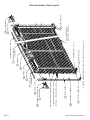
ROLLING CURTAIN DOOR
INSTALLATION, MAINTENANCE
& PARTS MANUAL
MODEL 988 & 988WL
WARNING
Read manual prior to installing door. Overhead doors are large, heavy objects that move with the help of springs
under extreme tension. Since moving objects and springs under tension can cause injuries, your safety and the
safety of others depends on you reading and following the information in this manual. Re-check your work prior to
operating door.
POTENTIAL HAZARD
EFFECT
PREVENTION
MOVING DOOR
Can Cause Serious
Keep people clear of opening while door is moving. Get help
Injury or Death
or use support when lifting new door into place.
EXTREME SPRING
TENSION
Can Cause Serious
Injury or Death
Installation, repairs, and adjustments must be made by a qualified
door mechanic using proper tools, methods, and instructions.
Before winding torsion spring, make sure door is fully open
and curtain is wrapped on barrel.
NOTE!
CAUTION
DO NOT CUT BANDS which hold door in a roll. You will be
informed when to cut bands within this manual. No
guarantee will be given or responsibility accepted by TracRite Door if door is not installed as instructed. For proper
operation, follow instructions given.
Use proper lifting equipment and correct lifting
procedures to avoid injury.
216 Wilburn Road, Sun Prairie, WI 53590
Phone: 800-448-8979; Fax: 800-236-8722
Technical Help Line: 888-700-TRAC (8722)
Web Site: www.tracrite.com
E-mail: [email protected]
This Manual MUST Be Left with the Owner.
#651100 REV. A 07 12 /05
Page 2
WA
LL
9. INTERIOR LOCK
KEEPER (PART OF 11)
WA
LL
9. INTERIOR LOCK
PULL ROPE HANDLE
(CENTERED ON DOOR)
** 2 PIECE GUIDES STANDARD ON ALL DOORS TALLER THAN 14' 10"**
6. BOTTOM ASSEMBLY
10. MOUNTING FASTENERS
8. DOOR GUIDE
OPTIONAL SPACEGUARD LATCH
OPTIONAL SPACEGUARD LOCK
OPTIONAL CURTAIN WINDLOCKS
7. BRACKET
12. SADDLE W / TENSIONER
11. DOOR STOP
1. DEAD AXLE
ASSEMBLY
3. SPRINGS
14. SPRING CLIP
4. AXLE
2. DRUMS
5. DOOR CURTAIN
ASSEMBLY
OPTIONAL DRAFT STOP
7. BRACKET
13. AXLE SADDLE
Door Assembly - Parts Layout
© 2005 TRAC-RITE DOOR, INC.
WARNING
Improper installation of anchoring devices or installation into aged or unsound concrete
block or other wall material may result in premature product wear, product failure,
property damage or serious personal injury.
Prior to beginning door installation, read the instruction
manual in its entirety. Please contact Trac-Rite with any
questions at 888-700-8722. Answering questions up front will
greatly reduce the probability of installation miscues.
1. GENERAL:
In this document, the following terms are defined as:
Warning - serious personal injury or death can result from
failure to follow instructions.
Caution - minor injury or property damage can result from
failure to follow instructions.
Note special attention should be given to the instructions.
NOTE!
Do not install this rolling steel curtain door unless
you read and understand the installation
instructions!
lading and packing list to reference when reporting shortages
or damage. Do not install damaged material without
authorization from Trac-Rite.
2.2 Door Width Verification: The door curtain width should
measure 5” greater than the framed opening width. If the door
is equipped with windlocks, the curtain width should measure
3” greater than the framed opening.
2.3 Framed Opening Verification:
• Proper size dimensionally?
• Opening square? Plumb?
• Is the jamb structurally/dimensionally adequate?
Reference paragraph 3. Jamb Preparation for specifics.
• Clearances? (Reference Figure 1)
3. JAMB PREPARATION:
3.1 Are the jambs structurally and/or dimensionally adequate
to accept door brackets and guides? Trac-Rite is not
responsible for the structural integrity of the jamb itself!
- Do not cut the bands which hold the door curtain in
a roll! This is performed once the door has been hung in
the opening.
WARNING
- Once the door has been installed, you will find full door
height strips of white felt tape on the inside of the door
curtain. Do not remove! It is not packaging material.
Do not use model 944 and 955 hardware on model
988 doors. It is not structurally adequate. If door
falls, serious injury and/or damage to door can
result.
2. INSPECTION:
2.1 Door and Hardware: Upon receiving the door shipment,
immediately inspect the door and hardware for damage.
Verify the product received with the packing list. Damages
and/or shortages should be reported immediately to Trac-Rite
customer service at 800-448-8979. Please have your bill of
3.2 Trac-Rite does not supply fasteners for attaching the
door brackets and guides to concrete or concrete masonry
jambs. Trac-Rite does supply fasteners for metal and wood
jambs.
• Door bracket to jamb fasteners must be 3/8” in
RECOMMENDED INSTALLATION CLEARANCES
C
C
C
OPENING HEIGHT
A *
B * WOOD/
MOTOR
MASONRY
STEEL
OPERATOR
7' -10 " - 16' - 0"
20"
22"
7.5"
9"
21.5"
7' - 10" - 16' - 0" WL
21"
23"
7.5"
9"
21.5"
* ADD 1" TO A AND B FOR INSULATED DOORS.
** IF CHAIN HOIST IS NOT PURCHASED, AXLE CAN BE CUT
OFF FOR EXTRA SIDE CLEARANCE
Figure 1.
©2005 TRAC-RITE DOOR, INC.
Page 3
diameter, and be constructed of ASTM A-307 steel or
greater.
• Door guide to jamb fasteners must be 1/4” in
diameter, and be constructed of ASTM A-307 steel or
greater.
3.3 Pre-drill jambs to accept door brackets; 7/16” diameter
holes for 3/8” nuts and bolts in steel jambs, proper size pilot
hole for 3/8” lag bolt in wood jambs. Hole locations are shown
in Figure 2. Do not pre-drill jambs for door guide installation.
NOTE: Door must be hung level to ensure proper tracking.
4.2 OPTIONAL REDUCED DRIVE SYSTEM Install the
sprocket on the preferred side of door assembly and secure
with 3- 3/8” x 1” bolts.
4.2.1 Slide the chain hoist assembly on the axle and align the
sprockets parallel to each other.
4.2.2 Connect the drive chain around both sprockets, using
the masterlink provided. Do not secure the chain hoist
assembly to the axle at this time.
4.3 Slide the axle saddle onto the axle after the chain hoist is
in place.
DOOR BRACKET HOLE LOCATIONS
2" 43 8" 3"
2" 43 8" 3"
4.4 On the opposite side of the reduced-drive chainhoist,
slide the saddle with the tension device on the axle (tensioner).
Slide the axle saddle onto the axle on the side with the reduceddrive chain hoist.
OPENING WIDTH
7"
OPENING WIDTH + 1112"
SIDE WITHOUT
OPERATOR
OPENING HEIGHT
OPENING HEIGHT
412"
SIDE WITH
OPERATOR
Figure 2.
4. DOOR PRE-ASSEMBLY:
NOTE!
OPTIONAL OPERATOR CAN BE INSTALLED ON
EITHER END OF DOOR ASSEMBLY.
4.1 Position the door in the opening as shown in Figure 3. Be
sure to place the door on protective material to prevent
damage to the curtain.
5. BRACKET MOUNTING:
5.1 Mount the Right and Left bracket according to the spacing
in Figure 2. Make sure there is enough spacing for the
reduced-drive chain hoist on the chosen side of the door
assembly. Fasten using the pre-drilled holes and fasteners
described in Section 3.
6. HOIST DOOR INTO OPENING:
WARNING
DO NOT allow persons to ride on forklift or other
hoisting equipment being used to lift the curtain
assembly into position. Do not permit any persons
to climb on ladders near the curtain assembly while it
is being hoisted. Should the curtain assembly slip,
SERIOUS INJURY or DEATH to persons standing on
ladders or riding on lifting equipment can occur.
6.1 Utilizing whatever method currently available (forklift, block
and tackle, etc.), hoist the door up over the mounted brackets.
Protect the door while lifting by padding the forks of the forklift.
6.2 Position the door on the brackets so the tensioner and
axle saddle rest safely on the top flange of the bracket. Make
sure arrows on the tensioner and axle saddle are pointing in
the correct direction.
6.3 Door should be positioned as close as possible to the
header and still be able to rotate and clear the bottom bar.
The door should also be centered in the opening.
NOTE DIRECTION AND POSITION
OF BOTTOM ASSEMBLY
WARNING
Do NOT allow door assembly to roll off brackets or
move sideways off edge of bracket. If door falls,
serious injury or death and/or damge to door can
result.
Figure 3.
Page 4
©2005 TRAC-RITE DOOR, INC.
6.4 Fasten the tensioner and the axle saddle to the bracket
using 4 - 3/8-16 X 1” hex bolts.
7. GUIDE POSITIONING
7.1 Position the guides against the jambs according to the
clearance shown in Figure 4 (Figure 5 if windlock model).
Loosely fasten the guides to allow slight adjustment (guides
on doors 14’-10” and taller will have a splice). DO NOT
install the remaining fasteners until such time as the
adjustment is true. Level one guide and loosely install a
second fastener in the bottom hole. If mounting to masonry,
install clips provided as shown in Figure 6. Align the clips
with the holes along the length of the guide and flush with
the back of the guide. (Anchors by others).
DOOR GUIDE
DOOR CURTAIN
BLOCK JAMB
MAINTAIN 18" TO 14" GAP (3-6MM)
BETWEEN GUIDE & WEAR GUARD
NON-MASONRY
FASTENING HOLES
MASONRY ANCHOR
MASONRY CLIP
TEK SCREWS
Figure 6.
EDGE OF DOOR CURTAIN
3
8"
on to the door bottom assembly, carefully cut the steel bands
and feed the door curtain into the guides, moving the door
stops aside to let the bottom bar move past. Pull the door
bottom assembly down to waist level.
CLEARANCE
INSIDE EDGE OF GUIDE
Figure 4.
WIND LOCK
CAUTION
Care must be taken that the door does not spin
around free as this may cause personal injury and/or
damage to the door. DO NOT grab the springs or
unbolt the springs while there is tension on the door
as this may cause personal injury.
WIND LOCK BAR
WIND LOCK BAR
DOOR CURTAIN
ROTATION DIRECTION
TOWARDS WALL
WIND LOCK
DOOR GUIDE
CONCRETE FILLED
BLOCK JAMB
TAPCON
MASONRY FASTENER
JAMB OPENING
SETBACK
DIMENSION
BOTTOM OF
DOOR CURTAIN
1
4" for WOOD or STEEL
1 1 4" for MASONRY
JAMB INTERIOR
W
AL
BANDS
(STRETCH WRAP &
CARDBOARD STRIPS)
L
DOOR CURTAIN
TRACK BOLTS
DOOR GUIDE
DOOR STOP
3
8"
clearance
VIEW A-A
Figure 5.
8. PRE-TENSIONING & TOP STOP ASSEMBLY:
8.1 Install the track bolts, door stops and whiz nuts in each
side guide as shown in Figure 7. Do not tighten at this time.
8.2 Bend the guide tabs out slightly (about 1/4"). Standing
inside the opening looking out, place your hand on top of the
door and push away from you rotating the door nest (Figure
7). Rotate the door nest two complete revolutions. Hanging
©2005 TRAC-RITE DOOR, INC.
WHIZ NUTS
Figure 7.
WARNING
Immediately install keepers and door stops. These
devices will prevent the door from rolling up and out
of the guides.
Page 5
8.3 Attach the two keepers to the bottom interior edge of the
door with one (1) 1/4" carriage bolt and whiz nut in each keeper.
(Figure 8)
8.4 Tighten door stops installed in paragraph 8.1 making
certain track bolts are seated in guides. (Figure 8)
W AL
L
DOOR BRACKET
HAND BENT GUIDE TAB
5
16"
DOOR STOP
CARRIAGE BOLT & NUT
DOOR GUIDE
1
4"
KEEPER
CARRIAGE BOLT & NUT
BOTTOM OF
DOOR CURTAIN
Figure 8.
NOTE!
After completeing Step 9, confirm the door is
operating as it should prior to installing any
remaining doors. This will reduce the risk of multiple
installation errors.
Figure 9.
10.3 Tighten all 3/8 -16 x 1” wizlock bolts that were loosened
in 10.1.
11. INTERIOR LOCK INSTALLATION:
11.1 Position door at waist level.
11.2 Assemble components as shown in Figure 10, noting
that two (2) high collar lock washers are placed over each 1/
4" one-way screw to allow the lockbar to slide freely.
9. GUIDE ADJUSTMENT:
9.1 With the door approximately 6" from the floor, adjust the
guides so if you grab the door by its bottom assembly, you
shall be able to move it laterally approximately 1/4". Once the
guides are adjusted properly, install the remaining fasteners
and firmly tighten them.
9.2 Attach guide warning label (shown in Figure 9) to the
guide at eye level.
9.3 Attach tension adjustment warning label (shown in Figure
9) either on the door bracket with the tensioner or to wall at
eye level.
10. FINAL POSITIONING:
10.1 With the door in the fully open position, loosen all 3/8-16
x 1” wizlock bolts that connect the axle saddles to the door
bracket.
10.2 Push the door assembly as close as possible toward the
header while also allowing it to rotate freely. Each end of the
door should be equal distance from the header. The curtain
must be centered in the opening.
Page 6
Figure 10.
11.3 As the 1/4" screws are being tightened, move the lockbar
to assure that the high collar lock washers are inside the slots
in the lockbar.
11.4 Mount the lock strike to the bottom of each guide, as
shown, with two (2) 1/4” carriage bolts and jamb nuts through
the pre-punched holes.
©2005 TRAC-RITE DOOR, INC.
12. OPERATORS:
12.1 Manual operation -- Pull rope handle: Tie a knot in one
end of the rope. Slide the plastic handle onto the rope and
pull the knot up into the handle. Pass the other end of the
rope through the hole in the center of the bottom edge of the
door and tie another knot in the end to keep the rope from
pulling through.
12.3 Reduced-drive operator — 8:1 chain hoist assembly
should be installed as described in Section 4 and shown in
Figure 11.
NOTE!
Tensioning should always be done on the side of the
door that the tension device is installed.
spring pin. Release tension by moving the pipe wrench
backwards (see Figure 12). Release the spring pin and the
cams will engage to hold tension on the door. Repeat as many
times as necessary.
41A72 SPROCKET
WARNING
AXLE
AXLE SADDLE
DOOR BRACKET
Serious injury may occur if the door tension is not
fully assumed by the pipe wrench before releasing
the tension on the tension device by pushing upward
on the spring pin. Never force the spring pin. The
door tension must be released before pushing on the
spring pin.
ROLLER CHAIN
HAND CHAIN NOT SHOWN
FOR DRAWING CLARITY
MAIN HOIST BODY
13.3 To add tension, grasp the end of the axle pipe with pipe
wrench and apply pressure downward. The cam locks will
disengage as pressure is being applied. The tensioner will
automatically grip the axle and hold the new tension.
CAM LOCK
Figure 11.
12.3.1 Feed hand chain through and around pocket wheel.
Shorten chain so that it does not lay on the floor (1' to 3' off
floor). Close chain making certain there are no twists in the
chain.
SET SCREW
12.3.2 Attach chain keeper clip to wall (4' to 5' above floor).
12.3.3 Before operating chain hoist make sure the chain hoist
assembly is secured to the axle.
PIPE WRENCH
13. TENSION ADJUSTMENT SYSTEM USE:
WARNING
Components under extreme spring tension can
cause SERIOUS INJURY or DEATH. Adjustments and
repairs must be made by a qualified door mechanic
using proper tools and instructions. DO NOT
attempt to adjust door tension unless the door is in
the “UP” position and “LOCKED” in place.
13.1 Before adjusting tension on door, loosen all 3/8-16 square
head set screws in the tensioner, axle saddle, and chain hoist
if applicable.
Figure 12.
13.4 Retighten all 3/8-16 square head set screws that were
loosened in 13.1.
WARNING
Never operate door if the 3/8-16 square head set
screws are not fully tightened on the axle saddles.
13.5 Repeat step 13 as needed.
13.2 To remove tension, grasp the end of the axle pipe with a
pipe wrench and apply a slight amount of pressure downward
and hold. Disengage the cam lock by pushing back on the
©2005 TRAC-RITE DOOR, INC.
Page 7
15.2.1 Periodically clean any accumulated dirt from guides;
remove any debris from the guide channels at the floor.
NOTE!
If the door is easy to close, but hard to open,
increase the spring tension. If the door is hard to
close, but easy to open, decrease spring tension.
14. OPTIONAL FIELD INSTALLED DRAFT STOP OR
BRUSH SEAL:
14.1 Place the door in the closed position before installing the
draft stop. Note that with the door down, the curtain may bow
slightly near the top towards the inside; this bowing is normal.
For the draft stop to be effective, it should follow the “bow” in
the door curtain so that it stays in contact across the entire
width of the door curtain. Starting at one end, attach to header
every 9 inches with appropriate fasteners. Cut to length if
necessary.
14.2 Place the door in the closed position before installing the
brush seal. Position brush seal so that it just touches the flat
portion of the curtain. See Figure 13. Fasten brush seals to
jamb every 12 inches with appropriate fasteners.
DOOR JAMB
BRUSH SEAL
15.3 LUBRICATION: Lubricate the following every six months
or more in dusty and/or wet operating environments.
15.3.1 Guides: Open the door. Spray silicone spray, Pledge™,
or Zep 45™ onto the door guide runners and inside the guide.
15.3.2 Lock: Spray the slide lock with silicone spray or
Pledge™ to promote smooth lock operation.
15.3.3 Chain Hoist Parts: Apply a small amount of oil to roller
chain.
16. REPLACEMENT PARTS
Part No. Description
Locks:
521226 Interior Lock Package
601811 SpaceGuard Latch Package
502705 SpaceGuard Lock
502721 Lock Out Key
Hardware:
650080 Bracket, Universal, RH, LH
502680 42" Rope (8' - 10' tall)
508840 72" Rope (10' - 12' tall)
508841 90" Rope (over 12' tall)
651000 Steel Jamb Package (651005 w/ Windlocks)
651001 Wood Jamb Package (651006 w/ Windlocks)
651002 Concrete Jamb Package
650060 Axle Saddle w/ Tensioner
650070 Axle Saddle
DOOR GUIDE
Figure 13.
CAUTION
Excessive force in operation may cause damage to
the door.
15. MAINTENANCE
15.1 INSPECTION: Visually inspect the entire door monthly
for general cleanliness and ease of operation.
15.1.1 Inspect the guides and curtain for wear and/or accidental
damage.
15.1.2 Inspect all fasteners and anchor bolts for loose,
damaged, or missing parts.
15.1.3 If door is equipped with a chain hoist mechanism,
inspect it for missing parts.
15.2 CLEANING: No specific cleaning procedures are required
for your Trac-Rite rolling door. Clean as needed following
good housekeeping practices.
Page 8
Springs:
650100
650110
650120
650130
600960
RH, 3.375" ID, 0.3125 wire, 49 coils, 15.63"
LH, 3.375" ID, 0.3125 wire, 49 coils, 15.63"
RH, 3.375" ID, 0.3125 wire, 68 coils, 21.56"
LH, 3.375" ID, 0.3125 wire, 68 coils, 21.56"
RH, 3.375" ID, 0.283 wire, 62 coils, 19.50"
Miscellaneous:
502290 Tube Astragal
521261 Felt Tape, 2”
502061 Guide Runner
502520 Draft Stop
504300 Touch-up Paint, Evergreen
504301 Touch-up Paint, Sunset Orange
504302 Touch-up Paint, Polar Blue
504303 Touch-up Paint, Royal Blue
504305 Touch-up Paint, Desert Tan
504306 Touch-up Paint, Continental Brown
504307 Touch-up Paint, Garnet
504308 Touch-up Paint, Iced White
50430A Touch-up Paint, Cedar Red
504325 Touch-up Paint, Shale
504323 Touch-up Paint, Bright White
Operators:
651050 8:1 Reduced Drive Chain Hoist
©2005 TRAC-RITE DOOR, INC.