1
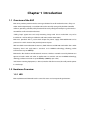
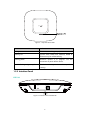
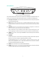
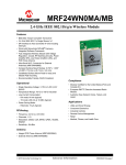
User Guide Wireless N Access Point EAP110/EAP120/EAP220 REV1.0.0 1910011184 FCC STATEMENT (EAP110) This equipment has been tested and found to comply with the limits for a Class B digital device, pursuant to part 15 of the FCC Rules. These limits are designed to provide reasonable protection against harmful interference in a residential installation. This equipment generates, uses and can radiate radio frequency energy and, if not installed and used in accordance with the instructions, may cause harmful interference to radio communications. However, there is no guarantee that interference will not occur in a particular installation. If this equipment does cause harmful interference to radio or television reception, which can be determined by turning the equipment off and on, the user is encouraged to try to correct the interference by one or more of the following measures: • • • • Reorient or relocate the receiving antenna. Increase the separation between the equipment and receiver. Connect the equipment into an outlet on a circuit different from that to which the receiver is connected. Consult the dealer or an experienced radio/ TV technician for help. This device complies with part 15 of the FCC Rules. Operation is subject to the following two conditions: 1) This device may not cause harmful interference. 2) This device must accept any interference received, including interference that may cause undesired operation. Any changes or modifications not expressly approved by the party responsible for compliance could void the user’s authority to operate the equipment. Note: The manufacturer is not responsible for any radio or TV interference caused by unauthorized modifications to this equipment. Such modifications could void the user’s authority to operate the equipment. FCC STATEMENT (EAP120&EAP220) This equipment has been tested and found to comply with the limits for a Class A digital device, pursuant to part 15 of the FCC Rules. These limits are designed to provide reasonable protection against harmful interference when the equipment is operated in a commercial environment. This equipment generates, uses, and can radiate radio frequency energy and, if not installed and used in accordance with the instruction manual, may cause harmful interference to radio communications. Operation of this equipment in a residential area is likely to cause harmful interference in which case the user will be required to correct the interference at his own expense. This device complies with part 15 of the FCC Rules. Operation is subject to the following two conditions: 1) This device may not cause harmful interference. 2) This device must accept any interference received, including interference that may cause undesired operation. Any changes or modifications not expressly approved by the party responsible for compliance could void the user’s authority to operate the equipment. Note: The manufacturer is not responsible for any radio or TV interference caused by unauthorized modifications to this equipment. Such modifications could void the user’s authority to operate the equipment. FCC RF Radiation Exposure Statement: This equipment complies with FCC RF radiation exposure limits set forth for an uncontrolled environment. This device and its antenna must not be co-located or operating in conjunction with any other antenna or transmitter. “To comply with FCC RF exposure compliance requirements, this grant is applicable to only Mobile Configurations. The antennas used for this transmitter must be installed to provide a separation distance of at least 20 cm from all persons and must not be co-located or operating in conjunction with any other antenna or transmitter.” CE Mark Warning (EAP110/EAP120) (EAP220) This is a class A product. In a domestic environment, this product may cause radio interference, in which case the user may be required to take adequate measures. National Restrictions(only for EAP220) This device is intended for home and office use in all EU countries (and other countries following the EU directive 1999/5/EC) without any limitation except for the countries mentioned below: Country Restriction Bulgaria None France Reason/remark General authorization required for outdoor use and public service Outdoor use limited to Military Radiolocation use. Refarming of the 2.4 GHz band 10 mW e.i.r.p. within the has been ongoing in recent years to allow current relaxed band 2454-2483.5 MHz regulation. Full implementation planned 2012 Italy None Luxembourg None Norway Implemented Russian Federation None If used outside of own premises, general authorization is required General authorization required for network and service supply(not for spectrum) This subsection does not apply for the geographical area within a radius of 20 km from the centre of Ny-Ålesund Only for indoor applications 5150-5250 MHz Country Restriction Reason/remark Bulgaria Not implemented Planned Croatia License required General authorization required if used outside own Italy premises Luxembourg None Russian Federation No info General authorization required for network and service supply (not for spectrum) Note: Please don’t use the product outdoors in France. IC STATEMENT This Class A digital apparatus complies with Canadian ICES-003. Cet appareil numérique de la classe A est conforme à la norme NMB-003 du Canada. Продукт сертифіковано згідно с правилами системи УкрСЕПРО на відповідність вимогам нормативних документів та вимогам, що передбачені чинними законодавчими актами України. Safety Information When product has power button, the power button is one of the way to shut off the product; When there is no power button, the only way to completely shut off power is to disconnect the product or the power adapter from the power source. Don’t disassemble the product, or make repairs yourself. You run the risk of electric shock and voiding the limited warranty. If you need service, please contact us. Avoid water and wet locations. NCC Notice & BSMI Notice 注意! 依據 低功率電波輻射性電機管理辦法 第十二條 經型式認證合格之低功率射頻電機,非經許可,公司、商號或使用者均不得擅自 變更頻率、加大功率或變更原設計之特性或功能。 第十四條 低功率射頻電機之使用不得影響飛航安全及干擾合法通行;經發現有干擾現象時, 應立即停用,並改善至無干擾時方得繼續使用。前項合法通信,指依電信規定作業之無線電 信。低功率射頻電機需忍受合法通信或工業、科學以及醫療用電波輻射性電機設備之干擾。 減少電磁波影響,請妥適使用。 安全諮詢及注意事項 ●請使用原裝電源供應器或只能按照本產品注明的電源類型使用本產品。 ●清潔本產品之前請先拔掉電源線。請勿使用液體、噴霧清潔劑或濕布進行清潔。 ●注意防潮,請勿將水或其他液體潑灑到本產品上。 ●插槽與開口供通風使用,以確保本產品的操作可靠並防止過熱,請勿堵塞或覆蓋開口。 ●請勿將本產品置放於靠近熱源的地方。除非有正常的通風,否則不可放在密閉位置中。 ●請不要私自打開機殼,不要嘗試自行維修本產品,請由授權的專業人士進行此項工作。 此為甲類資訊技術設備,于居住環境中使用時,可能會造成射頻擾動,在此種情況下,使用 者會被要求採取某些適當的對策。 This product can be used in the following countries: AT BG BY CA CZ DE DK EE ES FI FR GB GR HU IE IT LT LV MT NL NO PL PT RO RU SE SK TR UA US About this User Guide This User Guide is for EAP110, EAP120 and EAP220. Chapter 4 to Chapter 8 are only suitable for the EAP in Standalone mode. Refer to the EAP Controller User Guide when the EAP is managed by the EAP Controller software. Convention Unless otherwise noted, the EAP or the device mentioned in this guide stands for 300Mbps Wireless N Access Point EAP110, Wireless N Gigabit Access Point EAP120 and EAP220. CONTENTS Chapter 1 Introduction ...................................................................................................................................... 3 1.1 Overview of the EAP ........................................................................................................................... 3 1.2 Hardware Overview ............................................................................................................................ 3 1.2.1 LED ................................................................................................................................................... 3 1.2.2 Interface Panel............................................................................................................................. 4 1.2.3 Mounting Bracket....................................................................................................................... 6 Chapter 2 Network Topology .......................................................................................................................... 7 Chapter 3 Management Mode........................................................................................................................ 8 3.1 Standalone Mode................................................................................................................................. 8 3.2 Managed Mode .................................................................................................................................... 8 3.3 Switch to Standalone Mode ............................................................................................................. 8 Chapter 4 Network ........................................................................................................................................... 10 Chapter 5 Wireless ............................................................................................................................................ 11 5.1 5.2 Wireless Settings ............................................................................................................................... 12 5.1.1 Wireless Basic Settings .......................................................................................................... 13 5.1.2 SSIDs............................................................................................................................................. 14 5.1.3 Wireless Advanced Settings ................................................................................................ 18 5.1.4 Load Balance ............................................................................................................................. 19 Portal...................................................................................................................................................... 19 5.2.1 Portal Configuration ............................................................................................................... 20 5.2.2 Free Authentication Policy................................................................................................... 25 5.3 MAC Filtering ...................................................................................................................................... 27 5.4 Scheduler ............................................................................................................................................. 29 5.5 QoS ......................................................................................................................................................... 33 5.6 5.5.1 AP EDCA Parameters .............................................................................................................. 34 5.5.2 Station EDCA Parameters ..................................................................................................... 35 Rogue AP Detection......................................................................................................................... 36 5.6.1 Settings ....................................................................................................................................... 37 5.6.2 Detected Rogue AP List ........................................................................................................ 37 5.6.3 Trusted AP List .......................................................................................................................... 38 1 5.6.4 Chapter 6 6.1 Download/Backup Trusted AP List.................................................................................... 38 Monitoring ...................................................................................................................................... 40 AP ............................................................................................................................................................ 40 6.1.1 6.2 AP List .......................................................................................................................................... 40 SSID ........................................................................................................................................................ 45 6.2.1 6.3 SSID List....................................................................................................................................... 45 Client...................................................................................................................................................... 46 6.3.1 User List ....................................................................................................................................... 46 6.3.2 Portal Authenticated Guest ................................................................................................. 47 Chapter 7 7.1 Management ................................................................................................................................. 49 System Log .......................................................................................................................................... 49 7.1.1 Log List ........................................................................................................................................ 49 7.1.2 Log Settings............................................................................................................................... 50 7.2 Web Server .......................................................................................................................................... 51 7.3 Management Access ........................................................................................................................ 52 7.4 LED ON/OFF ........................................................................................................................................ 53 7.5 SSH.......................................................................................................................................................... 53 7.6 SNMP ..................................................................................................................................................... 54 Chapter 8 System .............................................................................................................................................. 57 8.1 User Account....................................................................................................................................... 57 8.2 Time Settings ...................................................................................................................................... 57 8.2.1 Time Settings ............................................................................................................................ 58 8.2.2 Daylight Saving ........................................................................................................................ 59 8.3 Reboot/Reset ...................................................................................................................................... 60 8.4 Backup & Restore .............................................................................................................................. 61 8.5 Firmware Upgrade ............................................................................................................................ 61 Appendix A: Specifications .................................................................................................................................... 63 2 Chapter 1 Introduction 1.1 Overview of the EAP EAP series products provide wireless coverage solutions for small-medium business. They can either work independently as standalone APs or be centrally managed by the EAP Controller software, providing a flexible, richly-functional but easily-configured enterprise-grade wireless network for small and medium business. “Celling lamp” appearance and easily mounting design with chassis make EAP easy to be installed on a wall or ceiling and blend in with most interior decorations. EAP110 is provided with a passive PoE adapter for power supply. EAP120/EAP220 can be powered via a PSE* device or the provided power adapter. With two built-in omnidirectional antennas, both EAP110 and EAP120 work within the 2.4GHz frequency band and apply 802.11 standards and 2*2MIMO technology, allowing packet transmission at up to 300Mbps. EAP220 has four built-in omnidirectional antennas. Wireless network created by EAP220 can operate at both 2.4GHz and 5GHz. It applies 802.11n standard and two 2*2MIMO technology, allowing packet transmission at up to 600Mbps (300Mbps per radio). *PSE: Power Sourcing Equipment, a device (switch or hub for instance) that will provide power in a PoE setup. 1.2 Hardware Overview 1.2.1 LED EAP110, EAP120 and EAP220 have the same LED status and corresponding indications. 3 Figure 1-1 Top View of the EAP LED Status Indication Solid green The device is working properly. Flashing red System errors. RAM, flash, Ethernet, WLAN or firmware may be malfunctioning. Flashing yellow Firmware update is in progress. Do not disconnect or power off the device. Double-flashing red, green, yellow The device is being reset to its factory default settings. 1.2.2 Interface Panel EAP110: Figure 1-2 Interface Panel of EAP110 4 EAP120/EAP220: Figure 1-3 Interface Panel of EAP120/EAP220 Please note that EAP110 does not have the CONSOLE port, POWER port and ON/OFF button. The interface panel components of the EAP, from left to right, are described in the following list. Kensington Security Slot: Secure the lock (not provided) into the security slot to prevent the device from being stolen. RESET: With the device powered on, press and hold the RESET button for about 8 seconds until the LED flashes red, then release the button. The device will restore to factory default settings. CONSOLE: This port is used to connect to the serial port of a computer or a terminal to check and monitor system information of the EAP120/EAP220. Note: CLI commands are not available in current software version. We will release a new version supporting CLI commands soon. Please pay close attention to our official website. ARROW 1: This arrow is used to align with ARROW 2 on the mounting bracket to lock the EAP into place. ETHERNET: For EAP110, this port is used to connect to the POE port of the provided PoE adapter for both data transmission and power supply through Ethernet cabling. For EAP120/EAP220, this port is used to connect to a router to transmit data or to a PSE (Power Sourcing Equipment), such as a PoE switch, for both data transmission and Power over Ethernet (PoE) through Ethernet cabling. ON/OFF: Press this button to turn on/off the EAP120/EAP220. POWER: The power port is used to connect the EAP120/EAP220 to an electrical wall outlet via power adapter. Please only use the provided power adapter. 5 Passive PoE Adapter: Power LED: The Power LED indicates the status of the electric current: green (0-0.8A), red (0.8A-1A). POE Port: This port is used to connect the ETHERNET port of the EAP110. LAN Port: This port is used to connect your LAN. 1.2.3 Mounting Bracket The following figure describes the structure of the mounting bracket. Figure 1-4 Layout of the Mounting Bracket 6 Chapter 2 Network Topology A typical network topology for the EAP is shown below. Figure 2-1 Typical Topology To deploy an EAP in your local network, a DHCP server is required to assign IP addresses to the EAP and clients. Typically, a router acts as the DHCP server. Ensure the EAPs are in the same subnet with the Controller Host in which the EAP Controller is installed. The EAP can be managed by the EAP Controller software, which is a management software specially designed for the TP-LINK EAP devices on a local wireless network, allowing you to centrally configure and monitor mass EAP devices using a web browser on your PC. For more information about the EAP Controller, please refer to the EAP Controller User Guide in the resource CD or download it from our official website: http://www.tp-link.com/en/support/download/ 7 Chapter 3 Management Mode 300Mbps Wireless N Access Point EAP110 and Wireless N Gigabit Access Point EAP120/EAP220 can either work under the control of the EAP Controller software or work independently as a standalone access point. When user establishes a large-scale wireless network, the management of every single AP in the network is complex and complicated. With the EAP Controller software, you can centrally manage the mass APs simply in a web browser. The Standalone mode applies to a relatively small-sized wireless network. EAPs in the Standalone mode cannot be managed centrally by the EAP Controller software. 3.1 Standalone Mode By default, the EAP works independently as a standalone access point. By entering the IP address of the standalone EAP, you can log in to its web interface and perform configurations. The factory default IP address configuration of the EAP is DHCP (Dynamic Host Configuration Protocol). Before you access the web interface of the EAP, please make sure the DHCP server works properly. Typically, a router acts as the DHCP server. Follow the steps below to log in to the web interface of a standalone EAP. 1. Launch a web browser, enter the DHCP address in the address field and press the Enter key. 2. Enter admin (all lowercase) for both username and password. 3.2 Managed Mode The EAP will become a managed AP once it is adopted via the EAP Controller software. Users can manage the AP via a web browser. Refer to the EAP Controller User Guide to know more about EAP Controller software. 3.3 Switch to Standalone Mode The web interface of a specific EAP is not available once this EAP is adopted by the EAP Controller. You can Forget the EAP via the EAP Controller to turn it back as a standalone AP. Refer to the EAP Controller User Guide to learn more. 8 TIPS: Proceed to the following chapters for information on using the EAP in standalone mode. EAP110 is taken as the example. 9 Chapter 4 Network On Network page you can configure the IP address of the standalone EAP. Figure 4-1 Network Page Dynamic/Static: By default, the EAP device obtains an IP address from a DHCP server (typically a router). Select Static to configure IP address manually. Fallback IP: If the EAP fails to get a dynamic IP address from a DHCP server within ten seconds, the fallback IP will work as the IP address of the device. After that, however, the device will keep trying to obtain an IP address from the DHCP server until it succeeds. DHCP Fallback IP/IP MASK: Enter the fallback IP/IP mask. DHCP Fallback Gateway: Enter the fallback gateway. 10 Chapter 5 Wireless Wireless page, consisting of Wireless Settings, Portal, MAC Filtering, Scheduler, QoS and Rogue AP Detection, is shown below. Figure 5-1 Wireless Page 11 5.1 Wireless Settings Following is the page of Wireless Settings. Figure 5-2 Wireless Settings Page 12 5.1.1 Wireless Basic Settings Figure 5-3 Wireless Basic Settings 2.4GHz Wireless Radio: Check the box to enable 2.4GHz Wireless Radio. Wireless Mode: Select the protocol standard for the wireless network. Wireless network created by the EAP is able to operate in the 2.4GHz frequency The EAP supports 802.11b/g/n, 802.11b/g, and 802.11n standards. It is recommended to select 802.11b/g/n, in which way clients supporting 11b, 11g or 11n mode can access your wireless network. EAP220 the wireless network can work within 2.4GHz and 5GHz frequency. Wireless network of EAP220 operating at 5GHz frequency band supports 802.11a/n, 802.11a and 802.11n standards. It is recommended to select 802.11a/n, in which way your wireless network can be connected by clients supporting 11a or 11n mode. Channel Width: Select the channel width of this device. Options include 20MHz, 40MHz and 20/40MHz (this device automatically selects 20MHz or 40MHz, and 20MHz will be used if 40MHz is not available). According to IEEE 802.11n standard, using a channel width of 40MHz can increase wireless throughput. However, users may choose lower bandwidth due to the following reasons: 1. To increase the available number of channels within the limited total bandwidth. 2. To avoid interference from overlapping channels occupied by other devices in the environment. 3. Lower bandwidth can concentrate higher transmit power, increasing stability of wireless links over long distances. Channel: Select the channel used by this device to improve wireless performance. 1/2412MHz means the Channel is 1 and the frequency is 2412MHz. The channel number varies in different regions. By default, channel is automatically selected. Tx power: Enter the transmit power value. By default, the value is 20. The maximum transmit power may vary among different countries or regions. 13 If the maximum transmit power is set to be larger than local regulation allows, the maximum Tx power regulated will be applied in actual situation. NOTE: In most cases, it is unnecessary to select maximum transmit power. Selecting larger transmit power than needed may cause interference to neighborhood. Also it consumes more power and will reduce longevity of the device. Select a certain transmit power is enough to achieve the best performance. 5.1.2 SSIDs SSIDs can work together with switches supporting 802.1Q VLAN. The EAP can build up to eight virtual wireless networks per radio for users to access. At the same time, it adds different VLAN tags to the clients which connect to the corresponding wireless network. It supports maximum 8 VLANs per radio. The clients in different VLAN cannot directly communicate with each other. Clients connected to the device via cable do not belong to any VLAN. Thus wired client can communicate with all the wireless clients despite the VLAN settings. Click in the Modify column, the following content will be shown. Figure 5-4 SSIDs Click to add up to 8 wireless networks per radio. SSID Name: Enter up to 32 characters as the SSID name. Wireless VLAN ID: Set a VLAN ID (ranges from 0 to 4094) for the wireless network. VLAN 0 means VLAN function is disabled. Wireless networks with the same VLAN ID are grouped to a VLAN. 14 SSID Broadcast: Enable this function, AP will broadcast its SSID to hosts in the surrounding environment, as thus hosts can find the wireless network identified by this SSID. If SSID Broadcast is not enabled, hosts must enter the AP’s SSID manually to connect to this AP. Security Mode: Select the security mode of the wireless network. For the security of wireless network, you are suggested to encrypt your wireless network. This device provides three security modes: WPA-Enterprise, WPA-PSK (WPA Pre-Shared Key) and WEP (Wired Equivalent Privacy). WPA-PSK is recommended. Settings vary in different security modes as the details are in the following introduction. Select None and the hosts can access the wireless network without password. Portal: Portal provides authentication service for the clients who want to access the wireless local area network. For more information, refer to 5.2 Portal. After Portal is enabled, the configurations in 5.2 Portal will be applied. SSID Isolation: After enabling SSID Isolation, the devices connected in the same SSID cannot communicate with each other. Modify: Click to open the page to edit the parameters of SSID. Click to delete the SSID. Following is the detailed introduction of security mode: WEP, WPA-Enterprise and WPA-PSK. WEP WEP (Wired Equivalent Privacy), based on the IEEE 802.11 standard, is less safe than WPAEnterprise or WPA-PSK. NOTE: WEP is not supported in 802.11n mode. If WEP is applied in 802.11n mode, the clients may not be able to access the wireless network. If WEP is applied in 11b/g/n mode (in the 2.4GHz frequency band) or 11a/n (in the 5GHz frequency band), the device may work at a low transmission rate. Figure 5-5 Security Mode_WEP Type: Select the authentication type for WEP. Auto: The default setting is Auto, which can select Open System or Shared Key automatically based on the wireless station's capability and request. 15 Open System: After you select Open System, clients can pass the authentication and associate with the wireless network without password. However, correct password is necessary for data transmission. Shared Key: After you select Shared Key, clients has to input password to pass the authentication, or it cannot associate with the wireless network or transmit data. Key Selected: You can configure four keys in advance and select one as the present valid key. Wep Key Format: Select the wep key format ASCII or Hexadecimal. Key Type: Hexadecimal: Hexadecimal format stands for any combination of hexadecimal digits (0-9, a-f, A-F) in the specified length. Select the WEP key length (64-bit, or 128-bit, or 152-bit) for encryption. Key Value: ASCII: ASCII format stands for any combination of keyboard characters in the specified length. 64-bit: You can enter 10 hexadecimal digits (any combination of 0-9, a-f, A-F without null key) or 5 ASCII characters. 128-bit: You can enter 26 hexadecimal digits (any combination of 0-9, a-f, AF without null key) or 13 ASCII characters. 152-bit: You can enter 32 hexadecimal digits (any combination of 0-9, a-f, AF without null key) or 16 ASCII characters. Enter the key value. WPA-Enterprise Based on RADIUS server, WPA-Enterprise can generate different passwords for different users and it is much safer than WPA-PSK. However, it costs much to maintain and is more suitable for enterprise users. At present, WPA-Enterprise has two versions: WPA-PSK and WPA2-PSK. Figure 5-6 Security Mode_WPA-Enterprise Version: Select one of the following versions: Auto: Select WPA-PSK or WPA2-PSK automatically based on the wireless station's capability and request. 16 WPA-PSK: Pre-shared key of WPA. WPA2-PSK: Pre-shared key of WPA2. Encryption: Select the encryption type, including Auto, TKIP, and AES. The default setting is Auto, which can select TKIP (Temporal Key Integrity Protocol) or AES (Advanced Encryption Standard) automatically based on the wireless station's capability and request. AES is more secure than TKIP and TKIP is not supported in 802.11n mode. It is recommended to select AES as the encryption type. RADIUS Server IP/Port: Enter the IP address/port of the RADIUS server. RADIUS Password: Enter the shared secret of RADIUS server to access the RADIUS server. Group Key Update period: Specify the group key update period in seconds. The value can be either 0 or at least 30. 0 means no update. NOTE: Encryption type TKIP is not supported in 802.11n mode. If TKIP is applied in 802.11n mode, the clients may not be able to access the wireless network of the EAP. If TKIP is applied in 11b/g/n mode (in the 2.4GHz frequency band) or 11a/n (in the 5GHz frequency band), the device may work at a low transmission rate. WPA-PSK Based on pre-shared key, security mode WPA-PSK is characterized by high security and simple configuration, which suits for common households and small business. WPA-PSK has two versions: WPA-PSK and WPA2-PSK. Figure 5-7 Security Mode_WPA-PSK Version: Auto: Select WPA or WPA2 automatically based on the wireless station's capability and request. WPA: Pre-shared key of WPA. WPA2: Pre-shared key of WPA2. 17 Encryption: Select the encryption type, including Auto, TKIP, and AES. The default setting is Auto, which can select TKIP (Temporal Key Integrity Protocol) or AES (Advanced Encryption Standard) automatically based on the wireless station's capability and request. AES is more secure than TKIP and TKIP is not supported in 802.11n mode. It is recommended to select AES as the encryption type. Wireless Password: Configure the WPA-PSK/WPA2-PSK password with ASCII or Hexadecimal characters. For ASCII, the length should be between 8 and 63 characters with combination of numbers, letters (case-sensitive) and common punctuations. For Hexadecimal, the length should be 64 characters (case-insensitive, 0-9, a-f, A-F). Group Key Update Period: Specify the group key update period in seconds. The value can be either 0 or at least 30. 0 means no update. 5.1.3 Wireless Advanced Settings Figure 5-8 Wireless Advanced Settings Beacon Interval: Beacons are transmitted periodically by the device to announce the presence of a wireless network for the clients. Beacon Interval value determines the time interval of the beacons sent by the device. You can specify a value from 40 to 100. The default value is 100 milliseconds. DTIM Period: This value indicates the number of beacon intervals between successive Delivery Traffic Indication Messages (DTIMs) and this number is included in each Beacon frame. A DTIM is contained in Beacon frames to indicate whether the access point has buffered broadcast and/or multicast data for the client devices. Following a Beacon frame containing a DTIM, the access point will release the buffered broadcast and/or multicast data, if any exists. You can specify the value between 1-255 Beacon Intervals. The default value is 1, indicating the DTIM Period is the same as Beacon Interval. An excessive DTIM period may reduce the performance of multicast applications. It is recommended to keep it by default. RTS Threshold: When the RTS threshold is activated, all the stations and APs follow the Request to Send (RTS) protocol. When the station is to send packets, it will send a RTS to AP to inform the AP that it will send data. After receiving the RTS, the AP notices other stations in the same wireless network to delay their transmitting of data. At the same time, the AP inform the requesting station to send data. The value range is from 1 to 2347 bytes. The default value is 2347, which means that RTS is disabled. 18 Fragmentation Threshold: 5.1.4 Specify the fragmentation threshold for packets. If the size of the packet is larger than the fragmentation threshold, the packet will be fragmented into several packets. Too low fragmentation threshold may result in poor wireless performance caused by the excessive packets. The recommended and default value is 2346 bytes. Load Balance By restricting the maximum number of clients accessing the EAPs, Load Balance helps to achieve rational use of network resources. Figure 5-9 Load Balance Load Balance: Disable by default. Click ON to enable the function. After enabling it, you can set a number for maximum associated clients to control the wireless access. Maximum Associated Clients: Enter the number of clients to be allowed for connection to the EAP. The number ranges from 1 to 99. 5.2 Portal Portal authentication enhances the network security by providing authentication service to the clients who want to access the wireless local network. Portal is also called web authentication. The users have to log in a web page to establish verification. Network resources can be classified into different types for different users. Part of them can be accessed for free by the clients; while some specific resources can only be accessed by authorized users. What’s more, you can customize the authentication login page and specify a URL which the newly authenticated client will be redirected to. Please refer to Portal Configuration or Free Authentication Policy according to your need. 19 Following is the page of Portal. Figure 5-10 Portal Page NOTE: To apply Portal in a wireless network, please go to Wireless→Wireless Settings→SSIDs to enable Portal of a selected SSID. 5.2.1 Portal Configuration Three authentication types are available: No Authentication, Local Password and External RADIUS Server. 1. No Authentication:Users are required to finish only two steps: agree with the user protocol and click the Login button. 20 2. Local Password:Users are required to enter the preset user name and password, which are saved in the EAP. 3. External RADIUS Server:Users are required to enter the preset user name and password, which are saved in the database of the RADIUS server. The RADIUS server acts as the authentication server, which allows you to set different user name and password for different users. Refer to the following content to configure Portal based on actual network situations. No Authentication Figure 5-11 Portal Configuration_No Authentication Authentication Type: Select No Authentication. Authentication Timeout: After successful verification, an authentication session is established. Authentication Timeout decides the active time of the session. Within the active time, the device keeps the authentication session open with the associated client. To reopen the session, the client needs to log in the web authentication page and enter the user name and password again once authentication timeout is reached. By default, authentication timeout is one hour. Select Custom from the dropdown list to customize the parameter. Redirect: Disable by default. Redirect specifies that the portal should redirect the newly authenticated clients to the configured URL. 21 Redirect URL: Enter the URL that a newly authenticated client will be directed to. Portal Customization: Select Local Web Portal, the authentication login page will be provided by the built-in portal server. The page configured below will be presented to users as the login page. Words can be filled in Input Box 1 and Input Box 2. Enter up to 31 characters as the title of the authentication login page in Input Box 1, like “Guest Portal of TP-LINK”. Enter the terms presented to users in Input Box 2. The terms can be 1 to 1023 characters long. 22 Local Password Figure 5-12 Portal Configuration_Local Password Authentication Type: Select Local Password. Username: Enter the user name for local authentication. Password: Enter the password for local authentication. Please refer to No Authentication to configure Authentication Timeout, Redirect, Redirect URL, and Portal Customization. External RADIUS Server External RADIUS Server provides two types of portal customization: Local Web Portal and External Web Portal. The authentication login page of Local Web Portal is provided by the builtin portal server of the EAP, as Figure 5-13 shown. The authentication login page of External Web Portal is provided by external portal server, as Figure 5-14 shown. 23 1. Local Web Portal Figure 5-13 Portal Configuration_External RADIUS Server_Local Web Portal Authentication Type: Select External RADIUS Server. RADIUS Server IP: Enter the IP address of the RADIUS server. Port: Enter the port for authentication service. RADIUS Password: Enter the shared secret of RADIUS server to log in to the RADIUS server. Please refer to No Authentication to configure Authentication Timeout, Redirect, Redirect URL, and Portal Customization. 24 2. External Web Portal Figure 5-14 Portal Configuration_External RADIUS Server_External Web Portal Authentication Type: Select External RADIUS Server. RADIUS Server IP: Enter the IP address of the RADIUS server. Port: Enter the port for authentication service. RADIUS Password: Enter the shared secret of RADIUS server to log in to the RADIUS server. Portal Customization: Select External Web Portal. External Web Portal URL: Enter the authentication login page’s URL, which is provided by the remote portal server. Please refer to No Authentication to configure Authentication Timeout, Redirect and Redirect URL. 5.2.2 Free Authentication Policy Free Authentication Policy allows clients to access network resources for free. On the lower part of the Portal page you can configure and view free authentication policies. Figure 5-15 Free Authentication Policy 25 Click to add a new authentication policy and configure its parameters. Figure 5-16 Configure Free Authentication Policy Policy Name: Enter a policy name. Source IP Range: Enter the source IP address and subnet mask of the clients who can enjoy the free authentication policy. Leaving the field empty means all IP addresses can access the specific resources. Destination IP Range: Enter the destination IP address and subnet mask for free authentication policy. Leaving the field empty means all IP addresses can be visited. When External Radius Server is configured and External Web Portal is selected, please set the IP address and subnet mask of your external web server as the Destination IP Range. Source MAC: Enter the source MAC address of the clients who can enjoy the free authentication policy. Leaving the field empty means all MAC addresses can access the specific resources. Destination Port: Enter the destination port for free authentication policy. Leaving the field empty means all ports can be accessed. Status: Check the box to enable the policy. 26 Click the button OK in Figure 5-16 and the policy is successfully added as Figure 5-17 shows. Figure 5-17 Add Free Authentication Policy Here is the explanation of Figure 5-17: The policy name is Policy 1. Clients with IP address range 192.168.2.0/24 are able to visit IP range 10.10.10.0/24. Policy 1 is enabled. Click to edit the policy. Click to delete the policy. 5.3 MAC Filtering MAC Filtering uses MAC addresses to determine whether one host can access the wireless network or not. Thereby it can effectively control the user access in the wireless network. Figure 5-18 MAC Filtering Page 27 Settings Enable MAC Filtering: Check the box to enable MAC Filtering. Station MAC Group Follow the steps below to add MAC groups. Step 1: Click , two tables will be shown. Figure 5-19 Station MAC Group Step 2: Click and fill in a name for the MAC group. Figure 5-20 Add a Group Step 3: Click and input the MAC address you want to organize into this group. 28 Figure 5-21 Add a Group Member Click in Modify column to edit the MAC group name or MAC address. Click to delete the MAC group or group member. MAC Filtering Association Figure 5-22 MAC Filtering Association SSID Name: Displays the SSID of the wireless network. Band: Displays the frequency band the wireless network operates at. MAC Group Name: Select a MAC group from the drop-down list to allow or deny its members to access the wireless network. Action: Allow: Allow the access of the stations specified in the MAC group. Deny: Deny the access of the stations specified in the MAC group. 5.4 Scheduler Scheduler allows you to configure rules with specific time interval for radios to operate, which automates the enabling or disabling of the radio. 29 Figure 5-23 Scheduler Page Settings Scheduler: Check the box to enable Scheduler. Association Mode: Select Associated with SSID/AP, you can perform configurations on the SSIDs/AP. The display of Scheduler Association is based on your option here. Scheduler Profile Configuration Follow the steps below to add rules. Step 1: Click , two tables will be shown. Figure 5-24 Scheduler Profile Configuration 30 Step 2: Click and input a profile name for the rule. Figure 5-25 Add a Profile Step 3: Click and configure the recurring schedule for the rule. Figure 5-26 Add a Rule 31 Scheduler Association This zone will display different contents based on your selection of association mode in Settings. 1. Associated with SSID Figure 5-27 Scheduler Association_Associated with SSID SSID Name: Displays the SSID of the standalone AP. Band: Displays the frequency band which the wireless network operates at. Profile Name: Select a profile name from the drop-down list. Profile name is configured in Scheduler Profile Configuration. Action: Select Radio On/Off to turn on/off the wireless network during the time interval set for the profile. 2. Associated with AP Figure 5-28 Scheduler Association_Associated with AP AP: Displays the name of the device. AP MAC: Displays the MAC address of the device. Profile Name: Select a profile name from the drop-down list. Profile name is configured in Scheduler Profile Configuration. Action: Select Radio On/Off to turn on/off the wireless network during the time interval set for the profile. 32 5.5 QoS The EAP supports Quality of Service (QoS) to prioritize voice and video traffic over other traffic types. In normal use, the default values for the EAP device and station EDCA should not need to be changed. Changing these values affects the QoS provided. Figure 5-29 QoS Page Wi-Fi Multimedia (WMM): By default, WMM is enabled. After WMM is enabled, the device has the QoS function to guarantee the transmission of audio and video packets with high priority. 33 5.5.1 AP EDCA Parameters AP Enhanced Distributed Channel Access (EDCA) parameters affect traffic flowing from the EAP device to the client station. Figure 5-30 AP EDCA Parameters Queue: Displays the transmission queues: Data 0>Data 1>Data 2>Data 3. Arbitration InterFrame Space: A wait time for data frames. The wait time is measured in slots. Valid values for AIFS are from 1 to 15. Minimum Contention Window: An input to the algorithm that determines the initial random backoff wait time (window) for retry of a transmission. Maximum Contention Window: The upper limit (in milliseconds) for the doubling of the random backoff value. Maximum Burst This parameter applies only to traffic flowing from EAP to the client station. This value specifies (in milliseconds) the maximum burst length allowed for packet bursts on the wireless network. A packet burst is a collection of multiple frames transmitted without header information. The decreased overhead results in higher throughput and better performance. Valid values for Maximum Burst are from 0 to 8192 and should be exactly divided by 32. 34 5.5.2 Station EDCA Parameters Station EDCA parameters affect traffic flowing from the client station to the EAP device. Figure 5-31 Station EDCA Parameters Queue: Displays the transmission queues: Data 0>Data 1>Data 2>Data 3. Arbitration InterFrame Space: A wait time for data frames. The wait time is measured in slots. Valid values for AIFS are 1 through 15. Minimum Contention Window: An input to the algorithm that determines the initial random backoff wait time (window) for retry of a transmission. Maximum Contention Window: The upper limit (in milliseconds) for the doubling of the random backoff value. TXOP Limit: The Transmission Opportunity (TXOP) is an interval of time, in milliseconds, when a WME client station has the right to initiate transmissions onto the wireless medium towards the EAP device. Valid values for TXOP Limit are from 0 to 8192 and should be exactly divided by 32. No Acknowledgement: Select Enable to specify that the EAP device should not acknowledge frames with QosNoAck as the service class value. By default, it is disabled. Unscheduled Automatic Power Save Delivery: Select Enable to enable APSD, which is a power management method. APSD is recommended if VoIP phones access the network through the EAP device. By default, it is enabled. 35 5.6 Rogue AP Detection A Rogue AP is an access point that has been installed on a secure network without explicit authorization from a system administrator. The EAP device can scan all channels to detect all APs in the vicinity of the network. If rogue APs are detected, they are shown on the Detected Rogue AP List. If an AP listed as a rogue is legitimate, you can add it to the Trusted AP List. Figure 5-32 Rogue AP Detection Page 36 5.6.1 Settings Figure 5-33 Enable Rogue AP Detection Rogue AP Detection: Check the box to enable Rogue AP Detection, then click Save. 5.6.2 Detected Rogue AP List Information about the detected rogue APs is displayed in the list. By default, the status of the detected rogue AP is unknown. You can click Known in Action column to move the AP to the Trusted AP List. Figure 5-34 Detected Rogue AP List Click to scan rogue APs. Make sure you have enabled Rogue AP Detection and saved the setting before you click the button. Action: Click Known to move the AP to the Trusted AP List. After the configurations are saved, the moved AP will not be displayed in the Detected Rogue AP List. MAC: The MAC address of the rogue AP. SSID: The SSID for the rogue AP. Band: Displays the frequency band which the wireless network of the rogue AP operates at. Channel: The channel on which the rogue AP is currently broadcasting. Security: Displays the enabling or disabling of the security mode of the wireless network. 37 Beacon Interval: The beacon interval used by the rogue AP. Signal: The strength of the radio signal emitting from the rogue AP. Beacon frames are transmitted by an AP at regular intervals to announce the existence of the wireless network. The default behavior is to send a beacon frame once every 100 milliseconds (or 10 per second). 5.6.3 Trusted AP List Information about the trusted APs is displayed in the list. Figure 5-35 Trusted AP List Action: Click Unknown to move the AP out of the Trusted AP List. MAC: The MAC address of the trusted AP. SSID: The SSID for the trusted AP. Band: Displays the frequency band which the wireless network of the trusted AP operates at. Channel: The channel on which the trusted AP is currently broadcasting. Security: Displays the enabling or disabling of the security mode of the wireless network. 5.6.4 Download/Backup Trusted AP List You can import a list of trusted APs from a saved list which is acquired from another AP or created from a text file. The AP whose MAC address is in the Trusted AP List will not be detected as a rogue. You can also backup a list and save it in your PC. Figure 5-36 Download/Backup Trusted AP List 38 Save Action: Select Download (PC to AP) to import a trusted AP list to the device. Select Backup (AP to PC) to copy the trusted AP list to your PC. Source File Name: Click Browse and choose the path of a saved trusted AP list or to save a trusted AP list. File Management: Select Replace to import the list and replace the contents of the Trusted AP List. Select Merge to import the list and add the APs in the imported file to the APs currently shown in the Trusted AP List NOTE: EAP device does not have any control over the APs in the Detected Rogue AP List. 39 Chapter 6 Monitoring On Monitoring page, you can monitor the network running status and statistics based on AP, SSID and Client. 6.1 AP AP List on the Monitoring page displays the device name, its MAC address and the number of clients. Below the AP List the AP’s detailed information will be shown, including Device Information, Wireless Settings, LAN Information, Client, LAN Traffic and Radio Traffic. Figure 6-1 AP Monitoring 6.1.1 AP List Figure 6-2 AP List 40 Device Name: Displays the device name. MAC: Displays the MAC address of the EAP. Num of Clients: Displays the number of clients connected to the EAP. Device Information Figure 6-3 Device Information Device Name: Displays the device name. Device Model: Displays the model of the device. Firmware Version: Displays the firmware version of the device. If you want to upgrade the firmware, please refer to 8.5 Firmware Upgrade. System Time: Displays the system time of the device. If you want to adjust the system time, please refer to 8.2.1 Time Settings. Uptime: Displays the time that has elapsed since the last reboot. CPU: Displays the CPU occupancy, which helps you to preliminarily judge whether the device functions properly. Memory: Displays the memory usage , which helps you to preliminarily judge whether the device functions properly. 41 Wireless Settings Figure 6-4 Wireless Settings Region: Displays the region you’ve selected. Channel/Frequency: Displays the channel number and the operating frequency. If you want to change them, please refer to 5.1.1 Wireless Basic Settings. Channel Width: Displays the spectral width of the radio channel used by the device. If you want to change it, refer to 5.1.1 Wireless Basic Settings. IEEE802.11 Mode: Displays the radio standard used for operation of your device. If you want to change it, refer to 5.1.1 Wireless Basic Settings. Max TX Rate: Displays the maximum data rate at which the device should transmit wireless packets. Transmit Power: Displays the maximum average transmit power of the device. If you want to change it, refer to 5.1.1 Wireless Basic Settings. LAN Information Figure 6-5 LAN Information MAC Address: Displays the MAC address of the device. IP Address: Displays the IP address of the device. Subnet Mask: Displays the subnet mask of the device. 42 LAN Port: Displays the maximum transmission rate and duplex mode (half-duplex or full-duplex) of the port. Client Figure 6-6 Client MAC: Displays the MAC address of the client of the AP selected in AP List. SSID: Displays the SSID the client is connected to. SNR(dB): Signal to Noise Ratio, the power ratio between the received wireless signal strength and the environmental noise strength. The bigger the value of SNR, the better network performance the device provides. CCQ(%): Displays the wireless Client Connection Quality (CCQ). CCQ refers to the ratio of current effective transmission bandwidth and the theoretically maximum available bandwidth. CCQ reflects the actual link condition. Rate(Mbps): Displays the data rate at which the client transmits wireless packets. Down(Byte): Displays the throughput of the downstream data. Up(Byte): Displays the throughput of the upstream data. Active Time: Displays the amount of time the client has been connected to the device. LAN Traffic Click LAN Traffic and you can monitor the data transmission status of the LAN port. Figure 6-7 LAN Traffic 43 Rx/Tx Packets: Displays the total amount of packets received/sent on the LAN port. Rx/Tx Bytes: Displays the total amount of data (in bytes) received/sent on the LAN port. Rx/Tx Dropped Packets: Displays the total amount of dropped packets received/sent on the LAN port. Rx/Tx Errors: Displays the total amount of error packets received/sent on the LAN port. Radio Traffic Click Radio Traffic and you can monitor the data transmission status of the wireless network. Figure 6-8 Radio Traffic Rx/Tx Packets: Displays the total amount of packets received/sent by the wireless network. Rx/Tx Bytes: Displays the total amount of data (in bytes) received/sent by the wireless network. Rx/Tx Dropped Packets: Displays the total amount of dropped packets received/sent by the wireless network. Rx/Tx Errors: Displays the total amount of error packets received/sent by the wireless network. 44 6.2 SSID Figure 6-9 SSID Monitoring 6.2.1 SSID List In SSID List you can monitor the related parameters of the wireless network. Figure 6-10 SSID List SSID Name: Displays the SSID name. If you want to modify it, please refer to 5.1.2 SSIDs. VLAN ID: Displays the VLAN which the SSID belongs to. If you want to change the VLAN ID, please refer to 5.1.2 SSIDs. Num of Clients: Displays the number of clients connected to the SSID. If you want to get more information about these clients, please refer to 5.1.2 SSIDs. SSID Broadcast: Displays the enabling or disabling of SSID broadcast. If you want to modify it, please refer to 5.1.2 SSIDs. Band: Displays the frequency band the wireless network is operating at. Security: Displays the security mode the wireless network is applying. If you want to modify it, please refer to 5.1.2 SSIDs. Portal: Displays the enabling or disabling of Portal. If you want to modify it, please refer to 5.1.2 SSIDs. MAC Filtering: Displays the enabling or disabling of MAC Filtering. If you want to modify it, please refer to 5.1.2 SSIDs. 45 Isolation: Displays the enabling or disabling of SSID Isolation. If you want to modify it, please refer to 5.1.2 SSIDs. Down(Byte): Displays the throughput of the downstream data. Up(Byte): Displays the throughput of the upstream data. 6.3 Client From User List, you can monitor the status of all the clients connected to the EAP including those who are authenticated. Figure 6-11 Client Monitoring 6.3.1 User List Figure 6-12 User List MAC: Displays the MAC address of the client. Access Point: Displays the name of the device to which the client is connected. SSID: Displays the SSID the client is connected to. 46 SNR(dB): Signal to Noise Ratio, the power ratio between the received wireless signal strength and the environmental noise strength. The bigger the value of SNR, the better network performance the device provides. CCQ(%): Displays the wireless Client Connection Quality (CCQ). CCQ refers to the ratio of current effective transmission bandwidth and the theoretically maximum available bandwidth. CCQ reflects the actual link condition. Rate(Mbps): Displays the data rate at which the client transmits wireless packets. Down(Byte): Displays the throughput of the downstream data. Up(Byte): Displays the throughput of the upstream data. Active Time: Displays the amount of time the client has been connected to the device. 6.3.2 Portal Authenticated Guest The Portal Authenticated Guest displays information about clients that have set up valid authentication. Figure 6-13 Portal Authenticated Guest MAC: Displays the MAC address of the authenticated client. Access Point: Displays the name of the device to which the authenticated client is connected SSID: Displays the SSID the authenticated client is connected to. SNR(dB): Signal to Noise Ratio, the power ratio between the received wireless signal strength and the environmental noise strength. The bigger the value of SNR, the better network performance the device provides. CCQ(%): Displays the Client Connection Quality (CCQ) of the authenticated client. CCQ refers to the ratio of current effective transmission bandwidth and the theoretically maximum available bandwidth. CCQ reflects the actual link condition. Rate(Mbps): Displays the data rate at which the authenticated client transmits wireless packets. Down(Byte): Displays the throughput of the downstream data. Up(Byte): Displays the throughput of the upstream data. 47 Active Time: Displays the amount of time the authenticated client has been connected to the root AP. Action: Click Unauthorize to stop giving authorization to the clients connected to the wireless network. 48 Chapter 7 Management Management page is mainly used for device management and maintenance. 7.1 System Log System log records information about hardware, software as well as system issues and monitors system events. With the help of system log, you can get informed of system running status and detect the reasons for failure. Following is the page of System Log. Figure 7-1 System Log Page 7.1.1 Log List From Log List you can view detailed information about hardware, software, system issues and so on. 49 Figure 7-2 Log List 7.1.2 Log Settings You can choose the way to receive system logs in Log Settings zone, where these parameters can be configured: Enable Auto Mail, Enable Server and Enable Nvram. Figure 7-3 Log Settings Enable Auto Mail If Auto Mail is enabled, system logs will be sent to a mailbox. The following content will be shown. Figure 7-4 Enable Auto Mail From: Enter the sender’s email address. To: Enter the recipient’s email address, which will receive the system logs. 50 SMTP Server: Enter the IP address of the SMTP server. Enable Authentication: Generally users are required to log in to the SMTP server by entering user name and password. Time Mode: User Name: Enter the sender’s email address. Password: Enter the password of the sender’s email address. Confirm Password: Enter the password again for confirmation. System logs can be sent at specific time or time interval. Fixation Time: Set a fixed time, for example, 15:00. The recipient will receive the system logs sent by the device at 15:00 every day. Period Time: Set a time interval, for example, 5 hours. The recipient will receive the system logs sent by the device every 5 hours. Enable Server System logs can also be sent to a server. After Auto Mail Feature is enabled, the following content will be shown. Figure 7-5 Enable Server System Log Server IP: Enter the IP address of the remote server. System Log Server Port: Enter the port of the remote server. Enable Nvram By default, Nvram is disabled. Check the box to enable Nvram, system logs will be saved after power supply is cut. 7.2 Web Server You can log in web management interface, thereby manage and maintain the device. 51 Following is the page of Web Server. Figure 7-6 Web Server Page HTTPS: HTTPS (Hypertext Transfer Protocol Secure) is enabled by default. Secure Server Port: Designate a secure server port for web server in HTTPS mode. By default the port is 443. Server Port: Designate a server port for web server in HTTP mode. By default the port is 80. Session Timeout: Set the session timeout time. If you do nothing with the web management page within the timeout time, the system will log out automatically. Please login again if you want to go back to web management page. 7.3 Management Access Management Access Control allows you to configure up to four MAC addresses of the hosts that are allowed to log in to the web management page of the EAP. Click Add PC’s MAC and the MAC address of the current host will be added to MAC address list. 52 Following is the page of Management Access. Figure 7-7 Management Access Page MAC Authentication: Check the box to enable MAC Authentication. After MAC Authentication is enabled, only the PCs in MAC address list can log in the device’s web management page. By default this function is disabled. All PCs in LAN can log in and manage the device. MAC1~MAC4: Enter the MAC addresses of the PCs which are authorized to log in the device. 7.4 LED ON/OFF Following is the page of LED ON/OFF. By default the LED is on. Figure 7-8 LED ON/OFF 7.5 SSH This device supports the SSH Server function that allows users to login and manage it through SSH connection on the SSH client software. 53 SSH (Secure Shell) is a security protocol established on application and transport layers. SSHencrypted-connection is similar to a telnet connection, but essentially the old telnet remote management method is not safe, because the password and data transmitted with plain-text can be easily intercepted. SSH can provide information security and powerful authentication when you login this device remotely through an insecure network environment. It can encrypt all the transmission data and prevent the information in remote management from being leaked. Following is the page of SSH. Figure 7-9 SSH Page Server Port: Enter the server port. By default, it is port 22. SSH Login: Check the box to enable SSH Server. By default, it is disabled. 7.6 SNMP The device can be configured as an SNMP agent. SNMP (Simple Network Management Protocol), the most widely applied network management protocol, provides a management framework to monitor and maintain Internet devices. Main functions of SNMP include monitoring network performance, detecting and analyzing network error, configuring network devices, and so on. When networks function properly, SNMP can perform the functions of statistics, configuration and testing. When networks have troubles, SNMP can detect and restore these troubles. An SNMP consists of three key components: manager, agent and MIB (Management Information Base). SNMP manager is a client program operating at workstation, assisting network administrators to accomplish most network device management tasks. An agent is a networkmanagement software module that resides on a managed device and responsible for receiving and dealing with data sent by managing device. Generally the managed devices are network devices including hosts, bridges, switches and routers. MIB is the collection of managed devices. It defines a series of properties of the managed devices. Every SNMP agent has its own MIB. 54 Once the device has become an SNMP agent, it is able to receive and process request messages from SNMP manager. Following is the page of SNMP. Figure 7-10 SNMP Page SNMP Agent: Enable SNMP Agent and the SNMP Agent will collect the information of this device and respond to information requests from one or more management systems. SysContact: Enter the textual identification of the contact person for this managed node. SysName: Enter an administratively-assigned name for this managed node. SysLocation: Enter the physical location of this managed node. Get Community: Community refers to a host group aiming at network management. Get Community only has the read-only right of the device's SNMP information. The community name can be considered a group password. The default setting is public. Get Source: Defines the IP address (for example, 10.10.10.1) or subnet for management systems that can serve as Get Community to read the SNMP information of this device. The format of subnet is “IP address/bit” (such as 10.10.10.0/24). The default is 0.0.0.0, which means all hosts can read the SNMP information of this device. Set Community: Set Community has the read and write right of the device's SNMP information. Enter the community name that allows read/write access to the device's SNMP information. The community name can be considered a group password. The default setting is private. 55 Set Source: Defines the IP address (for example, 10.10.10.1) or subnet for management systems that can serve as Set Community to read and write the SNMP information of this device. The format of subnet is “IP address/bit” (such as 10.10.10.0/24). The default is 0.0.0.0, which means all hosts can read and write the SNMP information of this device. NOTE: Defining community can allow management systems in the same community to communicate with the SNMP Agent. The community name can be seen as the shared password of the network hosts group. Thus, for the security, we suggest modifying the default community name before enabling the SNMP Agent service. If the field of community is blank, the SNMP Agent will not respond to any community name. 56 Chapter 8 System System page is mainly used to configure some basic information like user account and time, and realize functions including reboot, reset, backup, restore and upgrade the device. 8.1 User Account You can change the username and password to protect your device from unauthorized login. We recommend that you change the default user password on the very first system setup. Figure 8-1 User Account Page 8.2 Old User Name/Password: Enter the present user name and password of the admin account to get the permission of modification. New User Name/Password: Enter a new user name and password for the admin account. Both values are case-sensitive, up to 64 characters and with no space. Confirm New Password: Enter the new password again. Time Settings System time represents the device system’s notion of the passing of time. System time is the standard time for Scheduler and other time-based functions. You can manually set the system time, configure the system to acquire its time settings from a preconfigured NTP server or synchronize the system time with the PC’s clock. The device supports DST (daylight saving time). 57 Figure 8-2 Time Settings 8.2.1 Time Settings Figure 8-3 Time Settings Click the button and the device will obtain GMT time from NTP server. IP address of the NTP server has to be filled in. Click the button, your PC’s time will be obtained as the device’s system time. Time zone: Select your local time zone from the drop-down list. Date: Set the current date, in format MM/DD/YYYY. For example, for November 25, 2014, enter 11/25/2014 in the field. Time: Specify the device’s time. Select the number from the drop-down list in time format HH/MM/SS. 58 Primary/Secondary NTP Server: If you’ve selected Get GMT from an NTP server, please input the primary NTP sever address and an alternative NTP server address. 8.2.2 Daylight Saving Figure 8-4 Daylight Saving Daylight Saving: Enable or disable the DST. DST is disabled by default. Mode: Options include Predefined Mode, Recurring Mode and Date Mode. Please refer to the following content for more information. Predefined Mode Figure 8-5 Predefined Mode Mode: Select Predefined Mode. Predefine Country: Select a predefined DST configuration. Europe is the predefined country by default. USA: Second Sunday in March, 02:00 ~ First Sunday in November, 02:00 European: Last Sunday in March, 01:00 ~ Last Sunday in October, 01:00 Australia: First Sunday in October, 02:00 ~ First Sunday in April, 03:00 New Zealand: Last Sunday in September, 02:00 ~ First Sunday in April, 03:00 59 Recurring Mode Figure 8-6 Recurring Mode Mode: Select Recurring Mode. The configuration is recurring in use. Time Offset: Specify the time adding in minutes when Daylight Saving Time comes. Start/End: Select starting time and ending time of Daylight Saving Time. Date Mode Figure 8-7 Date Mode 8.3 Mode: Select Date Mode. Time Offset: Specify the time adding in minutes when Daylight Saving Time comes. Start/End: Select starting time and ending time of Daylight Saving Time. Reboot/Reset Figure 8-8 Reboot & Reset Click Reboot to restart the device. Click Reset to restore the device to factory default settings. 60 8.4 Backup & Restore Figure 8-9 Backup & Restore You can save the current configuration of the EAP as a backup file and restore the configuration via a backup file. Back up the settings before you upgrade the device or upload a new configuration file can prevent it from being lost. Restore function helps you to restore the device to previous settings by uploading a backup file. 8.5 Firmware Upgrade Figure 8-10 Firmware Upgrade Please log in http://www.tp-link.com/en/support/download/ to download the latest system file. Click Browse to choose the firmware file. Click Upgrade to upgrade the devices. 61 NOTE: 1. Please select the proper software version that matches your hardware to upgrade. 2. To avoid damage, please do not turn off the device while upgrading. 3. After upgrading, the device will reboot automatically. 62 Appendix A: Specifications HARDWARE FEATURES Model EAP110 Interface Kensington lock slot RESET button EAP120 EAP220 ETHERNET: 10/100Mbps Ethernet port (RJ45) ETHERNET: 10/100/1000Mbps Ethernet port (RJ45) CONSOLE port (RJ-45) Power connector (DC-2) Power Supply 24V/1A passive PoE adapter (included) PoE(802.3af-compliant, 36-57VDC, 0.2A Max) or external 12VDC/1A power supply PoE (802.3af-compliant, 36-57VDC, 0.4A Max)or external 12VDC/1.5A power supply Maximum Power Consumption 7.7W 4.4W 9.6W Antenna 2*3dBi embedded 2*4dBi embedded 4*4dBi embedded Mounting Ceiling/Wall mounting (kits included) Certification CE, FCC, RoHS Operating Temperature 0℃~40℃ (32℉~104℉) Operating Humidity 10%~90% non-condensing WIRELESS FEATURES Wireless Frequency 2.4GHz 2.4GHz & 5GHz Wi-Fi Standard IEEE 802.11b/g/n IEEE 802.11a/b/g/n Maximum Rate Up to 300Mbps Up to 600Mbps Max RF Transmission Power 23dBm 2.4GHz:23dBm 5GHz:20dBm Multiple SSIDs Up to eight per radio Captive Portal Authentication Support Wireless Security WEP WPA/WPA2-personal WPA/WPA2-enterprise Data 63