1
AT-TQ2450 Enterprise-class Wireless Access Point with IEEE802.11a/b/g/n Dual Radio Management Software User’s Guide 613-001821 Rev. A Copyright 2013 Allied Telesis, Inc. All rights reserved. This product includes software licensed under the BSD License. As such, the following language applies for those portions of the software licensed under the BSD License: Redistribution and use in source and binary forms, with or without modification, are permitted provided that the following conditions are met: * Redistributions of source code must retain the above copyright notice, this list of conditions and the following disclaimer. * Redistributions in binary form must reproduce the above copyright notice, this list of conditions and the following disclaimer in the documentation and/or other materials provided with the distribution. * Neither the name of Allied Telesis, Inc. nor the names of the respective companies above may be used to endorse or promote products derived from this software without specific prior written permission. THIS SOFTWARE IS PROVIDED BY THE COPYRIGHT HOLDERS AND CONTRIBUTORS "AS IS" AND ANY EXPRESS OR IMPLIED WARRANTIES, INCLUDING, BUT NOT LIMITED TO, THE IMPLIED WARRANTIES OF MERCHANTABILITY AND FITNESS FOR A PARTICULAR PURPOSE ARE DISCLAIMED. IN NO EVENT SHALL THE COPYRIGHT HOLDER OR CONTRIBUTORS BE LIABLE FOR ANY DIRECT, INDIRECT, INCIDENTAL, SPECIAL, EXEMPLARY, OR CONSEQUENTIAL DAMAGES (INCLUDING, BUT NOT LIMITED TO, PROCUREMENT OF SUBSTITUTE GOODS OR SERVICES; LOSS OF USE, DATA, OR PROFITS; OR BUSINESS INTERRUPTION) HOWEVER CAUSED AND ON ANY THEORY OF LIABILITY, WHETHER IN CONTRACT, STRICT LIABILITY, OR TORT (INCLUDING NEGLIGENCE OR OTHERWISE) ARISING IN ANY WAY OUT OF THE USE OF THIS SOFTWARE, EVEN IF ADVISED OF THE POSSIBILITY OF SUCH DAMAGE. Copyright (c) [dates as appropriate to package] by The Regents of the University of California - All rights reserved. Copyright (c) 2000-2003 by Intel Corporation - All rights reserved. Copyright (c) 1997-2003, 2004 by Thomas E. Dickey <[email protected]> - All rights reserved. Copyright (c) 2001-2009 by Brandon Long (ClearSilver is now licensed under the New BSD License.) Copyright (c) 1984-2000 by Carnegie Mellon University - All rights reserved. Copyright (c) 2002,2003 by Matt Johnston - All rights reserved. Copyright (c) 1995 by Tatu Ylonen <[email protected]> - All rights reserved. Copyright 1997-2003 by Simon Tatham. Portions copyright by Robert de Bath, Joris van Rantwijk, Delian Delchev, Andreas Schultz, Jeroen Massar, Wez Furlong, Nicolas Barry, Justin Bradford, and CORE SDI S.A. Copyright (c) 1989, 1991 by Free Software Foundation, Inc. (GNU General Public License, Version 2, June 1991). Copyright (c) 2002-2005 by Jouni Malinen <[email protected]> and contributors. Copyright (c) 1991, 1999 by Free Software Foundation, Inc. (GNU Lesser General Public License, Version 2.1, February 1999). Copyright (c) 1998-2002 by Daniel Veillard - All rights reserved. Copyright (c) 1998-2004 by The OpenSSL Project - All rights reserved. Copyright (c) 1995-1998 by Eric Young ([email protected]) - All rights reserved. This product also includes software licensed under the GNU General Public License available from: http://www.gnu.org/licenses/gpl2.html Allied Telesis is committed to meeting the requirements of the open source licenses including the GNU General Public License (GPL) and will make all required source code available. If you would like a copy of the GPL source code contained in this product, please send us a request by registered mail including a check for US$15 to cover production and shipping costs, and a CD with the GPL code will be mailed to you. GPL Code Request Allied Telesis Labs (Ltd) PO Box 8011 Christchurch, New Zealand No part of this publication may be reproduced without prior written permission from Allied Telesis, Inc. Allied Telesis™ and the Allied Telesis logo are trademarks of Allied Telesis, Incorporated. Ethernet™ is a trademark of the Xerox Corporation. Wi-Fi®, Wi-Fi Alliance®, WMM®, Wi-Fi Protected Access® (WPA), the Wi-Fi CERTIFIED logo, the Wi-Fi logo, the Wi-Fi ZONE logo, and the Wi-Fi Protected Setup logo are registered trademarks of the Wi-Fi Alliance. Wi-Fi CERTIFIED™, Wi-Fi Multimedia™, WPA2™ and the Wi-Fi Alliance logo are trademarks of the Wi-Fi Alliance. Microsoft is a registered trademark of Microsoft Corporation. All other product names, company names, logos or other designations mentioned herein are trademarks or registered trademarks of their respective owners. Allied Telesis, Inc. reserves the right to make changes in specifications and other information contained in this document without prior written notice. The information provided herein is subject to change without notice. In no event shall Allied Telesis, Inc. be liable for any incidental, special, indirect, or consequential damages whatsoever, including but not limited to lost profits, arising out of or related to this manual or the information contained herein, even if Allied Telesis, Inc. has been advised of, known, or should have known, the possibility of such damages. Contents Preface ............................................................................................................................................................11 Safety Symbols Used in this Document ...........................................................................................................12 Contacting Allied Telesis ..................................................................................................................................13 Chapter 1: Overview ......................................................................................................................................15 Features ...........................................................................................................................................................16 Management Modes and Methods ...................................................................................................................17 Starting a Management Session on the Access Point......................................................................................18 Starting the Initial Management Session on the Access Point .........................................................................19 Starting the Initial Management Session with a Direct Connection............................................................20 Starting the Initial Management Session without a DHCP Server .............................................................20 Starting the Initial Management Session with a DHCP Server ..................................................................21 Using the Management Menus and Windows ..................................................................................................22 Web Browser Menus..................................................................................................................................22 Saving Your Changes ................................................................................................................................24 Logging Off.................................................................................................................................................24 Chapter 2: Basic Settings Menu ...................................................................................................................25 Displaying Basic Information ............................................................................................................................26 Changing the Manager’s Login Name and Password ......................................................................................28 Changing the System Name, Contact, and Location........................................................................................29 Chapter 3: Manage Menu ..............................................................................................................................31 Assigning a Static IP Address to the Access Point...........................................................................................32 Assigning a Dynamic IP Address from a DHCP Server to the Access Point....................................................34 Setting VLAN IDs..............................................................................................................................................35 Management VLAN ID ...............................................................................................................................35 VLAN ID for Untagged Traffic ....................................................................................................................35 Enabling or Disabling Broadcast Ping Replies .................................................................................................36 Setting the Country Setting...............................................................................................................................37 Configuring Basic Radio Settings .....................................................................................................................39 Configuring the Radio Settings.........................................................................................................................42 Configuring Virtual Access Points ....................................................................................................................54 No Security.................................................................................................................................................57 IEEE 802.1x Security .................................................................................................................................57 Static WEP .................................................................................................................................................59 WPA Enterprise..........................................................................................................................................62 WPA Personal............................................................................................................................................65 Managing Wireless Distribution System Bridges..............................................................................................67 Configurations of WDS Bridges .................................................................................................................67 Radio..........................................................................................................................................................69 Radio Mode................................................................................................................................................69 Radio Channel ...........................................................................................................................................69 VAP0 ..........................................................................................................................................................69 Encryption ..................................................................................................................................................70 Guidelines ..................................................................................................................................................70 Preparing the Access Point for the WDS Bridge........................................................................................71 5 Contents Configuring the WDS Bridge ..................................................................................................................... 72 Static WEP ................................................................................................................................................ 74 WPA Personal ........................................................................................................................................... 75 Configuring the MAC Address Filter ................................................................................................................ 77 Generating Event Messages for Unknown Access Points ............................................................................... 80 Enabling Event Messages for Unknown Access Points ............................................................................ 80 Disabling Event Messages for Unknown Access Points ........................................................................... 82 Configuring the Access Point for the Optional AT-UWC Program ................................................................... 83 Enabling the Controller Client.................................................................................................................... 83 Disabling the Controller Client ................................................................................................................... 86 Chapter 4: Cluster Menu .............................................................................................................................. 87 Overview .......................................................................................................................................................... 88 Planning the Cluster......................................................................................................................................... 95 Creating or Adding Access Points to a Cluster ................................................................................................ 96 Managing the Access Points of the Cluster ..................................................................................................... 99 Removing an Access Point from a Cluster .................................................................................................... 100 Viewing the Wireless Clients of the Cluster ................................................................................................... 101 Using Automatic Channel Assignments ......................................................................................................... 103 Enabling Automatic Channel Assignments.............................................................................................. 103 Disabling Automatic Channel Assignments............................................................................................. 106 Viewing the Neighboring Access Points of the Cluster .................................................................................. 107 Chapter 5: Status Menu .............................................................................................................................. 111 Viewing the Associated Clients of an Access Point ....................................................................................... 112 Viewing Event Messages ............................................................................................................................... 114 Viewing System Event Messages ........................................................................................................... 115 Configuring the Event Log ....................................................................................................................... 117 Configuring the Syslog Client .................................................................................................................. 118 Disabling the Syslog Client...................................................................................................................... 119 Viewing Neighboring Access Points .............................................................................................................. 120 Displaying the IP Addresses of AT-UWC Programs ...................................................................................... 123 Displaying Statistics ....................................................................................................................................... 124 Viewing Basic IP and Radio Information ........................................................................................................ 128 Chapter 6: Services Menu .......................................................................................................................... 129 Configuring Quality of Service ....................................................................................................................... 130 Configuring SNMPv1 and v2c ........................................................................................................................ 137 Enabling or Disabling the LEDs ..................................................................................................................... 144 Configuring the HTTP Server......................................................................................................................... 145 Enabling the HTTP Server....................................................................................................................... 145 Disabling the HTTP Server...................................................................................................................... 146 Configuring the HTTPS Server ...................................................................................................................... 147 Enabling the HTTPS Server .................................................................................................................... 147 Disabling the HTTPS Server ................................................................................................................... 148 Configuring the Maximum Number of Active Management Sessions ............................................................ 149 Configuring the Management Session Timer................................................................................................. 150 Manually Setting the Date and Time .............................................................................................................. 151 Setting the Date and Time with the Network Time Protocol Client ................................................................ 153 Chapter 7: Maintenance Menu ................................................................................................................... 155 Restoring the Default Settings to the Access Point ....................................................................................... 156 Downloading the Configuration from the Access Point to Your Computer..................................................... 158 Restoring a Configuration to the Access Point .............................................................................................. 159 Rebooting the Access Point ........................................................................................................................... 160 Enabling or Disabling the Reset Button ......................................................................................................... 161 Switching the Primary and Secondary Management Software Images ......................................................... 162 Uploading New Versions of the Management Software to the Access Point................................................. 164 6 Figures Figure 1: Log On Window................................................................................................................................ 18 Figure 2: Horizontal Menus ............................................................................................................................. 22 Figure 3: Vertical Menus.................................................................................................................................. 23 Figure 4: Dropdown Menus ............................................................................................................................. 23 Figure 5: Provide Basic Settings Window........................................................................................................ 26 Figure 6: Modify Ethernet (Wired) Settings Window........................................................................................ 32 Figure 7: Modify Wireless Settings Window .................................................................................................... 37 Figure 8: Modify Radio Settings Window......................................................................................................... 43 Figure 9: Modify Virtual Access Point Settings Window .................................................................................. 56 Figure 10: 802.1x Authentication for VAPs...................................................................................................... 57 Figure 11: Static WEP Encryption for VAPs .................................................................................................... 59 Figure 12: WPA Enterprise for VAPs............................................................................................................... 62 Figure 13: WPA Personal for VAPs................................................................................................................. 65 Figure 14: WDS Bridge Used to Connect LAN Segments............................................................................... 67 Figure 15: WDS Bridge Used to Extend a Network......................................................................................... 67 Figure 16: Supported Configurations of WDS Bridges .................................................................................... 68 Figure 17: Invalid Loop Configuration of Access Points .................................................................................. 69 Figure 18: Invalid Loop Configuration of Access Points to a Wired Network Device ...................................... 69 Figure 19: Configure WDS Bridges to Other Access Points Window.............................................................. 72 Figure 20: Remote Address List ...................................................................................................................... 73 Figure 21: Static WEP on WDS Bridges.......................................................................................................... 74 Figure 22: WPA Personal on WDS Bridges .................................................................................................... 75 Figure 23: Configure MAC Filtering of Client Stations Window ....................................................................... 78 Figure 24: Event Message for Unknown Access Points.................................................................................. 80 Figure 25: Configure Pre-Configured Rogue AP Window ............................................................................... 81 Figure 26: Configure Managed Access Point Parameters Window................................................................. 83 Figure 27: Manage Access Points in the Cluster Window............................................................................... 96 Figure 28: Active Cluster in the Manage Access Points in the Cluster Window.............................................. 98 Figure 29: Manage Sessions Associated with the Cluster Window............................................................... 101 Figure 30: Automatically Manage Channel Assignments Window ................................................................ 103 Figure 31: Automatically Manage Channel Assignments Window - Automatic Channel Assignment Enabled ......................................................................................................................................................... 104 Figure 32: View Neighboring Access Points Window .................................................................................... 107 Figure 33: Neighbor Details........................................................................................................................... 108 Figure 34: View List of Currently Associated Client Stations......................................................................... 112 Figure 35: View Events Generated by this Access Point Window................................................................. 116 Figure 36: View Neighboring Access Points Window .................................................................................... 120 Figure 37: Displaying View List of Managing Switch IP Addresses and Base IP Port Obtained via DHCP....................................................................................................................................................... 123 Figure 38: Status Table in the View Transmit and Receive Statistics for this Access Point Window ............ 124 Figure 39: Transmit Statistics Table of the View Transmit and Receive Statistics for this Access Point Window................................................................................................................................................. 125 Figure 40: Receive Statistics Table of the View Transmit and Receive Statistics for this Access Point Window................................................................................................................................................. 126 Figure 41: View Settings for Network Interfaces Window.............................................................................. 128 7 List of Figures Figure 42: Modify QoS Queue Parameters.................................................................................................... Figure 43: SNMP Configuration Window ....................................................................................................... Figure 44: Control LEDs Window................................................................................................................... Figure 45: Configure Web Server Settings Window....................................................................................... Figure 46: Disable HTTP Server Prompt ....................................................................................................... Figure 47: Generate SSL Certificate Prompt ................................................................................................. Figure 48: Disable HTTPS Server Prompt ..................................................................................................... Figure 49: Modify How the Access Point Discovers the Time Window - Manually Setting the Date and Time ........................................................................................................................................................ Figure 50: Daylight Savings Time Fields ....................................................................................................... Figure 51: Modify How the Access Point Discovers the Time Window - Configuring the NTP Client............ Figure 52: Manage this Access Point’s Configuration Window...................................................................... Figure 53: Manage Firmware Window ........................................................................................................... 8 131 138 144 145 146 147 148 151 152 153 157 162 Tables Table 1. Review Description of this Access Point .......................................................................................... 27 Table 2. Modify Wireless Settings Window .................................................................................................... 40 Table 3. Modify Radio Settings Window ......................................................................................................... 44 Table 4. IEEE 802.1x ...................................................................................................................................... 57 Table 5. Static WEP ....................................................................................................................................... 59 Table 6. WPA Enterprise ................................................................................................................................ 63 Table 7. WPA Personal .................................................................................................................................. 65 Table 8. Available Encryption Settings on WDS Bridges ............................................................................... 70 Table 9. Static WEP on WDS Links ................................................................................................................ 74 Table 10. WPA Personal on WDS Links ........................................................................................................ 76 Table 11. Shared and Non-shared Parameters on the Access Points in a Cluster ........................................ 88 Table 12. Manage Sessions Associated with the Cluster Window ............................................................... 101 Table 13. Current Channel Assignments ...................................................................................................... 104 Table 14. Channel Reassignment Parameters ............................................................................................. 105 Table 15. View Neighboring Access Points Window .................................................................................... 108 Table 16. Neighbor Details Window ............................................................................................................. 109 Table 17. View List of Currently Associated Client Stations Window ........................................................... 112 Table 18. Event Messages Table ................................................................................................................. 116 Table 19. Neighboring Access Point Settings Window ................................................................................. 120 Table 20. Status Table Information .............................................................................................................. 125 Table 21. Transmit Statistics Table .............................................................................................................. 126 Table 22. Receive Statistics Table ............................................................................................................... 127 Table 23. Modify QoS Queue Parameters Window ...................................................................................... 131 Table 24. SNMP ........................................................................................................................................... 139 9 List of Tables 10 Preface This guide explains how to configure the AT-TQ2450 Wireless Access Point and the 2.4 GHz and 5 GHz radios with the web browser management windows. This preface contains the following sections: “Safety Symbols Used in this Document” on page 12 “Contacting Allied Telesis” on page 13 11 Preface Safety Symbols Used in this Document This document uses the following conventions. Note Notes provide additional information. Caution Cautions inform you that performing or omitting a specific action may result in equipment damage or loss of data. Warning Warnings inform you that performing or omitting a specific action may result in bodily injury. Warning Laser warnings inform you that an eye or skin hazard exists due to the presence of a Class 1 laser device. 12 AT-TQ2450 Wireless Access Point User’s Guide Contacting Allied Telesis If you need assistance with this product, you may contact Allied Telesis technical support by going to the Support & Services section of the Allied Telesis web site at www.alliedtelesis.com/support. You can find links for the following services on this page: 24/7 Online Support — Enter our interactive support center to search for answers to your product questions in our knowledge database, to check support tickets, to learn about RMAs, and to contact Allied Telesis technical experts. USA and EMEA phone support — Select the phone number that best fits your location and customer type. Hardware warranty information — Learn about Allied Telesis warranties and register your product online. Replacement Services — Submit a Return Merchandise Authorization (RMA) request via our interactive support center. Documentation — View the most recent installation and user guides, software release notes, white papers, and data sheets for your products. Software Downloads — Download the latest software releases for your managed products. For sales or corporate information, go to www.alliedtelesis.com/ purchase. 13 Preface 14 Chapter 1 Overview This chapter describes how to start the initial management session on the access point. This chapter contains the following sections: “Features” on page 16 “Management Modes and Methods” on page 17 “Starting a Management Session on the Access Point” on page 18 “Starting the Initial Management Session on the Access Point” on page 19 “Using the Management Menus and Windows” on page 22 15 Chapter 1: Overview Features The main features of the product are listed here: 16 Independent 2.4 and 5 GHz radios IEEE 802.11a/b/g IEEE 802.11n 2x2 MIMO chains with antenna diversity Data rates of 300 Mbps for the 2.4 GHz radio and 300 Mbps for the 5 GHz radio Wireless Distribution System (WDS) bridges Access point clustering Rogue access point detection Multiple SSIDs One 10/100/1000Base-T Ethernet port with Auto-Negotiation, auto MDI/MDIX, and IEEE 802.3af Power over Ethernet (PoE) MAC address filtering for wireless access security Broadcast and multicast rate limiting Virtual access points for multiple broadcast domains DHCP client RADIUS accounting with external RADIUS server Network Time Protocol (NTP) client Domain name server (DNS) client IEEE 802.1x authentication WPA-Personal and WPA-Enterprise with WPA, WPA2, TKIP, and CCMP (AES) authentication and encryption Static WEP encryption HTTP and HTTPS web browser management SNMPv1 and v2c management Quality of Service Event log Syslog client Table, wall, or ceiling installation AT-TQ2450 Wireless Access Point User’s Guide Management Modes and Methods The access point has two management modes: Stand-alone mode: Access points in the stand-alone mode are managed independently of each other. To configure a unit in this mode, you have to know its IP address or domain name, and the username and password of the manager account. This is the default setting for the access point. Cluster mode: The cluster management mode is intended for two or more access points that have similar configuration settings. When you change the parameter settings on an access point in a cluster, your changes are automatically communicated to the other access points. This reduces the need for having to configure the units individually. For cluster instructions, refer to Chapter 4, “Cluster Menu” on page 87. Here are the methods for managing the access point: Web browser: The management software on the access point has management windows for you to use with the web browser on your management workstations. They make it easy for you to configure all the parameter settings and features. The access point supports both non-secure HTTP and secure HTTPS management sessions. The default is HTTP. For instructions on how to enable or disable the HTTP and HTTPS servers on the access point, refer to “Configuring the HTTP Server” on page 145 and “Configuring the HTTPS Server” on page 147 AT-UWC Unified Wireless Controller program: This optional program allows you to manage the access points from a central point. For instructions on how to configure the unit for the wireless controller program, refer to “Configuring the Access Point for the Optional AT-UWC Program” on page 83. SNMPv1 and v2c: You may also use SNMP to manage some of the parameter settings of the device. The MIB is available from the Allied Telesis web site. It should be noted that you can configure only a limited number of parameters on the access point with SNMP. To manage all the parameters, you must use a web browser or the optional AT-UWC program. For instructions on how to configure the unit for SNMP, refer to “Configuring SNMPv1 and v2c” on page 137. The default setting for SNMP is disabled. The product does not support SNMPv3. 17 Chapter 1: Overview Starting a Management Session on the Access Point This section explains how to start a management session on the access from your management workstation. The procedure assumes that the access point has already been assigned an IP address. The address can be a static address that was manually assigned to the unit or it can be a dynamic address from a DHCP server. Note If the access point has not been assigned an IP address and is using its default address 192.168.1.230, refer to “Starting the Initial Management Session on the Access Point” on page 19 for instructions on how to start a management session. To start a management session on the access point, perform the following procedure: 1. Open the web browser on your management workstation. 2. Enter the IP address of the access point in the URL field of the web browser. You should now see the logon window, shown in Figure 1. Figure 1. Log On Window 3. Enter the username and password for the unit. The default values are “manager” for the username and “friend” for the password. The username and password are case-sensitive. 4. Click the Logon button. 18 AT-TQ2450 Wireless Access Point User’s Guide Starting the Initial Management Session on the Access Point If you just installed the device and are powering it on for the first time, it queries the subnet on the LAN port for a DHCP server. If a DHCP server responds to its query, the unit uses the IP address the server assigns to it. If there is no DHCP server, the access point uses the default IP address 192.168.1.230. There are a several ways to start the initial management session on the access point. One way is to establish a direct connection between your computer and the unit by connecting an Ethernet cable to the Ethernet port on the computer and the LAN port on the access point. This procedure requires changing the IP address on your computer to make it a member of the same subnet as the default IP address on the access point. You might perform this procedure if your network does not have a DHCP server and you want to configure the access point before connecting it to your network. The initial management session may also be performed while the device is connected to your network. However, If your network does not have a DHCP server, you still have to change the IP address of your computer to match the subnet of the default address of the access point. Furthermore, if your network is divided into virtual LANs (VLANs), you have to be sure to connect the access port and your computer to ports on an Ethernet switch that are members of the same VLAN. If your network has a DHCP server, use the IP address the server assigns it to it to start the management session. The instructions for starting the initial management session are found in the following sections: “Starting the Initial Management Session with a Direct Connection” on page 20 “Starting the Initial Management Session without a DHCP Server” on page 20 “Starting the Initial Management Session with a DHCP Server” on page 21 Note The initial management session of the access point has to be conducted through the LAN port because the default setting for the radios is off. 19 Chapter 1: Overview Starting the Initial Management Session with a Direct Connection To start the management session with a direct Ethernet connection between your computer and the access port, perform the following procedure: Note If the access point is using PoE, you may not perform this procedure because it involves a direct connection between your computer and the LAN port on the access point. You may either temporarily attach the power supply to the unit until after you have completed the initial management session or you may instead perform one of the other procedures for starting the initial management session. 1. Connect one end of a network cable to the LAN port on the access point and the other end to the Ethernet network port on your computer. (This requires removing the LAN cable you connected earlier in the hardware installation instructions.) 2. Change the IP address on your computer to 192.168.1.n, where n is a number from 1 to 254, but not 230. Refer to the documentation that accompanies your computer for instructions on how to set the IP address. 3. Set the subnet mask on your computer to 255.255.255.0. 4. Power on the access point. 5. Start the web browser on your computer. 6. Enter the IP address 192.168.1.230 in the URL field of the browser and press the Return key. You should now see the logon window, shown in Figure 1 on page 18. 7. Enter “manager” for the username and “friend” for the password. The username and password are case-sensitive. 8. Click the Logon button. Starting the Initial Management Session without a DHCP Server 20 This procedure explains how to start the initial management session on the access port when the LAN port is connected to an Ethernet switch on a network that does not have a DHCP server. To start the management session, perform the following procedure: 1. If your network has VLANs, check to be sure that your computer and the access port are connected to ports on the Ethernet switch that are members of the same VLAN. This might require accessing the management software on the switch and listing the VLANS and their port assignments. For example, if the access port is connected to a port that is a member of the Sales VLAN, your computer must be AT-TQ2450 Wireless Access Point User’s Guide connected to a port that is also a member of that VLAN. If your network is small and does not have VLANs or routers, you may connect your computer to any port on the Ethernet switch. 2. Change the IP address on your computer to 192.168.1.n, where n is a number from 1 to 254, but not 230. Refer to the documentation that accompanies your computer for instructions on how to set the IP address. 3. Set the subnet mask on your computer to 255.255.255.0. 4. Power on the access point. 5. Start the web browser on your computer. 6. Enter the IP address 192.168.1.230 in the URL field of the browser and press the Return key. You should now see the logon window, shown in Figure 1 on page 18. 7. Enter “manager” for the username and “friend” for the password. The username and password are case-sensitive. 8. Click the Logon button. Starting the Initial Management Session with a DHCP Server This procedure explains how to start the initial management session on the access port when the LAN port is connected to a network that has a DHCP server. This procedure assumes that you have already configured the DHCP server with the appropriate information for the access point (e.g., IP address and default gateway). To start the management session, perform the following procedure: 1. Power on the access point. 2. Start the web browser on your computer. 3. Enter the IP address of the access point in the URL field of the browser and press the Return key. This is the IP address assigned to the access point by the DHCP server. If you do not know the address, refer to the DHCP server. You should now see the logon window, shown in Figure 1 on page 18. 4. Enter “manager” for the username and “friend” for the password. The username and password are case-sensitive. 5. Click the Logon button. 21 Chapter 1: Overview Using the Management Menus and Windows Here is general information about the management menus and windows. Web Browser Menus You may control the appearance of the menus with the Navigator pulldown menu in the upper right corner of the web browser windows. The menu options are Horizontal Tabs, Vertical Tabs, and Dropdown Menus. The Horizontal Tabs selection displays the main menu in a row near the top of the windows. Clicking a menu selection displays the menu options in a row beneath the main menu. Figure 2 shows the Manage menu. Figure 2. Horizontal Menus The Vertical Tabs selection displays the menus in a column on the left side of the management windows, as shown in Figure 3 on page 23. 22 AT-TQ2450 Wireless Access Point User’s Guide Figure 3. Vertical Menus The Dropdown Menu option displays the main menu in a horizontal row near the top of the window. Menu options are displayed vertically when you move the mouse over the main menu. Figure 4 shows the Manage menu. Figure 4. Dropdown Menus 23 Chapter 1: Overview The menus contain the same selections and perform the same functions regardless of the format. You may switch between formats without interrupting your current session or having to stop and start it again. 24 Saving Your Changes You need to remember to click the Update button when you are finished configuring the parameters in a management window. The button is located in the bottom of the windows. When you click the button, the access point immediately activates your changes and saves them in the configuration file. If you navigate to a different window without clicking the Update button, your changes are lost and have to be reentered. Logging Off You should always log off when you are finished managing the unit. To log off, click the Log Off option in the upper right corners of the management windows. Chapter 2 Basic Settings Menu This chapter describes the management functions of the menu selections in the Basic Settings menu. The chapter contains the following sections: “Displaying Basic Information” on page 26 “Changing the Manager’s Login Name and Password” on page 28 “Changing the System Name, Contact, and Location” on page 29 25 Chapter 2: Basic Settings Menu Displaying Basic Information This section explains how to display the following information about the access point: IP address MAC address Firmware version number Build number Operational time To display the information, select Basic Settings from the main menus to display the “Provide basic settings” window. The information is contained in the Review Description of the Access Point section of the window. Refer to Figure 5. The fields are defined in Table 1 on page 27. Figure 5. Provide Basic Settings Window 26 AT-TQ2450 Wireless Access Point User’s Guide Table 1. Review Description of this Access Point Field Description IP Address Displays the IP address of the access point. For instructions on how to set the IP address, refer to “Assigning a Static IP Address to the Access Point” on page 32 or “Assigning a Dynamic IP Address from a DHCP Server to the Access Point” on page 34. MAC Address Displays is the MAC address of the device and radio 1. Radio 2 has a different MAC address. You may not change the MAC addresses of the device or radios. Firmware Version Displays is the version number of the management software on the access point. Build Number Displays the build number. This number and the firmware version number identify the management software. Time since system-up Displays the amount of time since the unit was reset or powered on. 27 Chapter 2: Basic Settings Menu Changing the Manager’s Login Name and Password This procedure explains how to change the login name and password of the manager account on the access point. The default values are “manager” and “friend”, respectively. The access point can have only one manager account. Changing the name and password does not affect your current management session of the access point. To change the login name and password for the manager account, perform the following procedure: 1. Select Basic Settings from the main menus. The access point displays the “Provide basic settings” window, shown in Figure 5 on page 26. 2. To change the manager name, select the Administrator Name field in the Provide Network Settings section of the window and enter the new name. Refer to Figure 5 on page 26. The name can be up to 12 alphanumeric characters. The first character must be a letter. It cannot be a number or special character. The name is case-sensitive. 3. To change the password, perform these steps: a. Select the Current Password field in the Provide Network Settings section of the window and enter the account’s current password. b. Select the New Password field and enter a new password of up to 32 alphanumeric characters. It may not contain spaces or any of these special characters: “, $, :, <, >, ’, &, *. The password is casesensitive. The new password is displayed as a series of asterisks on your screen. c. Select the Confirm New Password field and enter the new password again. 4. After editing the fields, click the Update button at the bottom of the window to activate your changes and save them in the configuration file on the access point. You must use the new manager name and password for all future management sessions on the unit. 28 AT-TQ2450 Wireless Access Point User’s Guide Changing the System Name, Contact, and Location This procedure explains how to identify the access point by defining the system name, the person responsible for managing the device, and its location. This information is optional. To change the system name, contact, and location information, perform the following procedure: 1. Select Basic Settings from the main menus. The access point displays the “Provide basic settings” window. Refer to Figure 5 on page 26. 2. To change the system name, select the System Name field in the System Settings section of the window and enter a new name. The name can be up to 64 alphanumeric characters. Spaces are allowed. The default name is “AT-TQ2450.” 3. To enter the name of the person responsible for managing the unit, select the System Contact field and enter a name. You might also include the phone number and email address of the individual in this field. The name can be up to 64 alphanumeric characters. Spaces are allowed. The default name is “unknown.” 4. To specify the location of the access point, select the System Location field and enter the location. The location can be up to 64 alphanumeric characters. Spaces are allowed. The default location is “unknown.” 5. After editing the fields, click the Update button at the bottom of the window to activate your changes and save them in the configuration file on the device. 29 Chapter 2: Basic Settings Menu 30 Chapter 3 Manage Menu This chapter describes the management functions of the menu selections in the Manage menu. The chapter contains the following sections: “Assigning a Static IP Address to the Access Point” on page 32 “Assigning a Dynamic IP Address from a DHCP Server to the Access Point” on page 34 “Setting VLAN IDs” on page 35 “Enabling or Disabling Broadcast Ping Replies” on page 36 “Setting the Country Setting” on page 37 “Configuring Basic Radio Settings” on page 39 “Configuring the Radio Settings” on page 42 “Configuring Virtual Access Points” on page 54 “Managing Wireless Distribution System Bridges” on page 67 “Configuring the MAC Address Filter” on page 77 “Generating Event Messages for Unknown Access Points” on page 80 “Configuring the Access Point for the Optional AT-UWC Program” on page 83 31 Chapter 3: Manage Menu Assigning a Static IP Address to the Access Point This section explains how to manually assign an IP address to the access point. The unit uses the address to communicate with devices on your network, such as management workstations, syslog servers, and RADIUS servers. The access point may have only one IP address. If you have a DHCP server on your network and prefer the access point obtain its IP configuration from the server, refer to “Assigning a Dynamic IP Address from a DHCP Server to the Access Point” on page 34. Note Changing the IP address of the access point interrupts your management session. To resume managing the device, you may have to change the IP address of your management workstation. To manually assign an IP address to the unit, perform the following procedure: 1. From the Manage menu, select Ethernet Settings. The access point displays the “Modify Ethernet (Wired) Settings” window in Figure 6. Figure 6. Modify Ethernet (Wired) Settings Window 2. From the Connection Type pull-down menu, select Static IP. 32 AT-TQ2450 Wireless Access Point User’s Guide The Static IP Address, Subnet Mask, and Default Gateway fields in the window are activated so that you can change their values. 3. Select the Static IP Address field and enter the new IP address for the access point. The default address is 192.168.1.230. 4. Select the Subnet Mask fields and enter the subnet mask for the IP address. The default subnet mask is 255.255.255.0. 5. Select the Default Gateway fields and enter the default gateway address for the unit. The default gateway address is 192.168.1.254. The default gateway is an IP address of an interface on a router or other Layer 3 routing device. It specifies the first hop to reaching the subnets or networks where your management devices, such as management workstations and syslog servers, reside. The access point can have only one default gateway and the network portion of the address must be the same as the IP address entered in step 3. You have to assign a default gateway to the access point. If your network does not have a default gateway or you do not want to assign one to the access point at this time, enter an unused IP address of the same network as the IP address entered in step 3. 6. If you want to specify the IP addresses of Domain Name servers, enter up to two IP addresses in the DNS Nameservers fields. If you have only one DNS IP address, you must enter it in the top field. 7. Click the Update button at the bottom of the window to activate and save your changes on the access point. Your management session is interrupted. 8. Start a new management session using the new IP address of the device. 33 Chapter 3: Manage Menu Assigning a Dynamic IP Address from a DHCP Server to the Access Point This section explains how to assign an IP address to the access point from a DHCP server. The unit uses the address to communicate with devices on your network, such as management workstations, syslog servers, and RADIUS servers. The access point may have only one IP address. If you network does not have a DHCP server or you prefer to manually assign it an IP address, refer to “Assigning a Static IP Address to the Access Point” on page 32. Note Changing the IP address of the access point interrupts your management session. To resume managing the device, you may have to change the IP address of your management workstation. To activate the DHCP client to have the access point obtain its IP address configuration from a DHCP server, perform the following procedure: 1. From the Manage menu, select Ethernet Settings. The access point displays the “Modify Ethernet (Wired) settings” window in Figure 6 on page 32. 2. From the Connection Type menu, select DHCP. This is the default setting. 3. If you want to manually specify the IP addresses of Domain Name servers, click Manual dialog button for DNS Nameservers and enter up to two IP addresses. If you have only one DNS IP address, you must enter it in the top address field. If you want the access point to use the DNS addresses provided by the DHCP server, click the Dynamic dialog circle. 4. Click the Update button at the bottom of the window to activate and save your changes on the access point. Your management session is interrupted. The DHCP client on the unit queries the subnet on the LAN port for a DHCP server. If it receives a response, it uses the IP configuration the server provides. If there is no response, the unit uses the default IP address 192.168.1.230. 5. To resume your management session on the device, enter the new IP address of the access point in the URL field of your web browser. 34 AT-TQ2450 Wireless Access Point User’s Guide Setting VLAN IDs The “Modify Ethernet (Wired) settings” window has two settings for VLAN IDs (VIDs). One setting is used to specify the management VLAN and the other is used to designate a VLAN for untagged traffic. Management VLAN ID The Management VLAN ID field in the “Modify Ethernet (Wired) settings” window is used to specify the VLAN of your management workstations. To specify the management VID, perform the following procedure: 1. From the Manage menu, select Ethernet Settings. The access point displays the “Modify Ethernet (Wired) settings” window in Figure 6 on page 32. 2. Select the Management VLAN ID field and enter a value of 1 to 4094. The number should be the VID of the VLAN where your management workstation is located. You may specify only one VID. 3. Click the Update button to activate and save your changes on the access point. VLAN ID for Untagged Traffic The Untagged VLAN and Untagged VLAN ID fields in the “Modify Ethernet (Wired) settings” window allow you to specify a VLAN for untagged traffic. To specify the VLAN, perform the following procedure: 1. From the Manage menu, select Ethernet Settings. The access point displays the “Modify Ethernet (Wired) settings” window in Figure 6 on page 32. 2. For the Untagged VLAN field, do one of the following: Click Enabled if you want to be able to designate one VLAN on the access point as an untagged VLAN. This is the default setting. Click Disabled if the access point is to handle only tagged packets. 3. If your selected Enabled, select the Untagged VLAN ID field and enter the ID number of the VLAN which is to carry untagged packets. You may enter only one VID. The default value is 1. 4. Click the Update button to activate and save your changes on the access point. 35 Chapter 3: Manage Menu Enabling or Disabling Broadcast Ping Replies You may configure the access point to either ignore or reply to ICMP echo requests to IP broadcast addresses, also referred to as broadcast pings. To configure broadcast ping replies, perform the following procedure: 1. From the Manage menu, select Ethernet Settings. The access point displays the “Modify Ethernet (Wired) settings” window in Figure 6 on page 32. 2. In the Directed Broadcast ICMP Reply field, do one of the following: If you want the access point to respond to broadcast pings, click the Enabled dialog circle. If you do not want the access point to respond to broadcast pings, click the Disabled dialog circle. 3. Click the Update button to activate and save your changes on the access point. 36 AT-TQ2450 Wireless Access Point User’s Guide Setting the Country Setting You should set the country setting of the access point as soon as you install the unit. This ensures that the device operates in compliance with the codes and regulations of your region or country. Note Changing the country setting of the access point disables both radios. Consequently, this procedure is disruptive to the operations of your network if the unit is actively forwarding network traffic. To set the country setting, perform the following procedure: 1. Select Wireless Settings from the Manage menu. The access point displays the “Modify wireless settings” window, shown in Figure 7. Figure 7. Modify Wireless Settings Window 2. Select the Country pull-down menu and select your country or region. 37 Chapter 3: Manage Menu Note If the Country pull-down menu is deactivated, the country parameter was set by the manufacturer and cannot be changed. Contact your Allied Telesis sales representative for assistance if the setting is not correct for your country or region. The access point displays a confirmation prompt. 3. Click OK to change the country setting or Cancel to cancel the procedure. If you click OK, the access point changes the country setting and disables both radios on the access point. For instructions on how to enable the radios and configure their settings, refer to “Configuring Basic Radio Settings” on page 39 and “Configuring the Radio Settings” on page 42. This procedure does not require clicking the Update button. You must now reboot the access point. The new country setting is not active until the unit is rebooted. To reboot the unit, either power off and on the unit or continue with these steps: 4. From the Maintenance menu, select Configuration. 5. Click the Reboot button in the To Reboot the Access Point section of the “Manage the Access Point’s Configuration” window. 6. When the access point displays a confirmation prompt, click OK to reboot the unit or Cancel to cancel the procedure. 7. To resume managing the unit, wait for it to complete initializing its management software and then start a new management session. 38 AT-TQ2450 Wireless Access Point User’s Guide Configuring Basic Radio Settings The management software has two windows for configuring the operational settings of the radios in the access point. The “Modify radios settings” window, described in “Configuring the Radio Settings” on page 42, is the main window for adjusting the radio parameters because it contains all the parameters, everything from operational mode to broadcast/multicast rate limiting. This is the window to use when you need to fine tune the properties of the radios. If you are only interested in configuring basic radio parameters, you may find everything you need in the “Modify wireless settings” window, which is the topic of this section. From this window you can perform these basic radio functions: Enable or disable a radio Select the operational mode Select the channel Enable or disable the station isolation mode When you change a radio parameter in the “Modify wireless settings” window, the change is reflected in the “Modify radios settings” window. So you could enable a radio here and perhaps select the channel, and then move to the “Modify radio settings” window to adjust additional parameters. The “Modify wireless settings” window does contain one parameter, however, that is not in the “Modify radio settings” window, and that is the station isolation mode parameter. The parameter determines whether the clients of a VAP can communicate with each other through the access point. That parameter can only be set from this window. To configure basic radio settings from the “Modify wireless settings” window, perform the following procedure: 1. From the Manage menu, select Wireless Settings. The access point displays the “Modify wireless settings” window. An example is shown in Figure 7 on page 37. 2. Configure the settings as needed. The parameters are described in Table 2 on page 40. 3. When you are finished configuring the parameters, click the Update button to activate and save your changes on the access point. 39 Chapter 3: Manage Menu Table 2. Modify Wireless Settings Window Field Radio On Off Description Enables or disables the radio. The selections are described here: - On: Enables the radio. You have to enable a radio before you can configure its parameter settings. - Off: Disables the radio. This is the default setting. MAC Address Displays the MAC address of the radio. This value cannot be changed Mode Specifies the Physical Layer (PHY) standard of the radio. The available modes depend on the radio and country. The modes are: - IEEE 802.11a: The access point accepts only 802.11a clients. - IEEE 802.11b/g: The access point accepts only 802.11b and 802.11g clients. - IEEE 802.11a/n: The access point accepts only 802.11a and 802.11n clients operating at 5 GHz. This is the default setting for the 5 GHz radio. - IEEE 802.11b/g/n: The access point accepts 802.11b, 802.11g, and 802.11n clients operating at 2.4 GHz. This is the default setting for the 2.4 GHz radio. - 2.4 GHz IEEE 802.11n: The access point accepts only 802.11n clients operating at 2.4 GHz. - 5 GHz IEEE 802.11n: The access point accepts only 802.11n clients operating at 5 GHz. 40 AT-TQ2450 Wireless Access Point User’s Guide Table 2. Modify Wireless Settings Window (Continued) Field Channel Description Specifies the channel for the radio in the access point. The number of available channels varies by radio, mode, and country. Here are the guidelines: - At the Auto setting, the access point sets the channel automatically. The access point listens on the channels and selects the one with the least traffic.This is the default setting. - You can select a channel from the pulldown menu. You may select only one channel. - The Auto selection is not available if you use the cluster feature to automatically assign the channels to the radios in the access points. For information, refer to “Using Automatic Channel Assignments” on page 103. Station Isolation Enables or disables station isolation. When station isolation is enabled, the access point does not allow the wireless clients of a VAP to communicate with each other, but does allow them to communicate with clients in other VAPs and with the wired LAN. The feature is disabled when the dialog box is empty and enabled when the dialog box has a check mark. The default setting is disabled. To activate or deactivate the feature, click the dialog box to insert or remove the check mark. 41 Chapter 3: Manage Menu Configuring the Radio Settings To configure the parameter settings of the 2.4 and 5 GHz radios, perform the following procedure: 1. From the Manage menu, select Radio. The management software displays the “Modify radio settings window,” shown in Figure 8 on page 43. 2. From the Radio pull-down menu, select a radio. Options 1 and 2 are the 2.4 and 5 GHz radios, respectively. The default is radio 1. You can configure only one radio at a time. 3. To activate a radio, click the On dialog circle for the Status option. You cannot configure a radio when its status is off. To deactivate a radio, click the Off dialog circle. 4. Configure the radio parameters, which are defined in Table 3 on page 44. 5. When you are finished configuring the parameters, click the Update button to activate and save your changes on the access point. 42 AT-TQ2450 Wireless Access Point User’s Guide Figure 8. Modify Radio Settings Window 43 Chapter 3: Manage Menu Table 3. Modify Radio Settings Window Parameter Mode Description Specifies the Physical Layer (PHY) standard of the radio. The available modes depend on the radio and country. The modes are: - IEEE 802.11a: The access point accepts only 802.11a clients. - IEEE 802.11b/g: The access point accepts only 802.11b and 802.11g clients. - IEEE 802.11a/n: The access point accepts only 802.11a and 802.11n clients operating at 5 GHz. This is the default setting for the 5 GHz radio. - IEEE 802.11b/g/n: The access point accepts 802.11b, 802.11g, and 802.11n clients operating at 2.4 GHz. This is the default setting for the 2.4 GHz radio. - 2.4 GHz IEEE 802.11n: The access point accepts only 802.11n clients operating at 2.4 GHz. - 5 GHz IEEE 802.11n: The access point accepts only 802.11n clients operating at 5 GHz. 44 AT-TQ2450 Wireless Access Point User’s Guide Table 3. Modify Radio Settings Window (Continued) Parameter Channel Description Specifies the radio channel. The available channels vary by radio, mode, and country. Here are the guidelines: - The Auto setting, the default setting, sets the channel automatically. The access point selects the channel with the least traffic. This is the default setting. - You can set the channel manually using the Channel pull-down menu. - The Auto selection is not available when automatic channel reassignment in the cluster feature is activated, as explained in Chapter 4, “Cluster Menu” on page 87. - If you select Auto, you may use the Eligible Channels parameter to restrict the channels from which the access point may choose. - You must set the channel manually if you are using the Wireless Distribution System (WDS) bridge feature, as explained in “Managing Wireless Distribution System Bridges” on page 67. Eligible Channels Specifies the available channels when the channel is selected automatically. This selection is unavailable when the channel is selected manually. The available channels vary by radio, mode, and country. To deselect a channel, click its dialog box to remove the check mark. The default is all available channels. 45 Chapter 3: Manage Menu Table 3. Modify Radio Settings Window (Continued) Parameter Periodical Channel Refresh Description Specifies whether the access point periodically reruns the channel selection process. Here are the guidelines: - This selection is only available when the Channel parameter is set to Auto. - Adding a check mark to the dialog box enables the feature. - Removing the check mark from the dialog box disables the feature. This is the default setting. - The access point runs the channel selection process every 24 hours, but only if the radio is not forwarding traffic from wireless clients. If it detects traffic, the access point delays the selection process for thirty minutes. Channel Bandwidth Specifies whether the radio should use a 40 MHz-wide channel or the legacy 20 MHz-wide channel. Here are the guidelines: - The 40 MHz-wide channel allows for higher data rates, but reduces the number of available channels for other wireless devices. - This parameter is only available with 802.11n modes. 46 AT-TQ2450 Wireless Access Point User’s Guide Table 3. Modify Radio Settings Window (Continued) Parameter Primary Channel Description Specifies the location of the Primary channel when a radio is operating at 40 MHz. A 40 MHz channel consists of two 20 MHz channels. They are contiguous in the frequency domain and referred to as the Primary and Secondary channels. The Primary channel is used by 802.11n clients that support only a 20 MHz channel bandwidth, and for legacy clients. You may use this parameter to specify the Primary channel of the 40 MHz bandwidth. The options are described here: - Upper: Designates the upper 20 MHz channel of the 40 MHz bandwidth as the Primary channel. - Lower: Designates the lower 20 MHz channel of the 40 MHz bandwidth as the Primary channel. This is the default setting. This parameter is only available with 802.11n modes. 47 Chapter 3: Manage Menu Table 3. Modify Radio Settings Window (Continued) Parameter Short Guard Interval Supported Description Specifies the dead time interval, in nanoseconds, between OFDM symbols. The guard interval prevents Inter-Symbol and Inter-Carrier Interference (ISI, ICI). The 802.11n mode supports a reduction in the interval from 800 nanoseconds, defined in the a and g standards, to 400 nanoseconds. This may provide up to a 10% improvement in data throughput. The selections are described here: - Yes: The access point uses a 400 ns guard interval when communicating with clients that also support the feature. This is the default setting. - No: The access point uses an 800 ns guard interval. This parameter is only available with the 802.11n modes. 48 AT-TQ2450 Wireless Access Point User’s Guide Table 3. Modify Radio Settings Window (Continued) Parameter Multidomain Regulatory Mode Description Specifies whether a radio should operate in the Multidomain Regulatory Mode (World Mode) and include the country code in its beacons and probe responses. This allows client stations to operate in any country without reconfiguration. This feature only applies to radio 1 because it operates in the g band (2.4 GHz band). This selection does not apply to radio 2 because it operates in the a band (5 GHz band) and always includes the country code in its beacons, as specified in the 802.11h standard. The settings are described here: - Enabled: Activates the Multidomain Regulatory Mode (World Mode) and includes the country code in the beacons and probe responses. - Disabled: Disables the Multidomain Regulatory Mode (World Mode) and prevents the transmission of the country code in beacons and probe responses. 49 Chapter 3: Manage Menu Table 3. Modify Radio Settings Window (Continued) Parameter Protection Description Enables or disables rules that guarantee that transmissions do not cause interference with legacy stations or applications. The possible settings are describe here: - Auto: This setting enables protection when legacy devices are within range of the radio. - Off: This setting disables the protections. Legacy clients and access points within range may be affected by 802.11n transmissions. Here are the guidelines: - The protection applies to 802.11n and 802.11b/g. - Activating protection does not prevent clients from associating with the access point. 50 Beacon Interval Specifies the time interval, in milliseconds, for transmissions of beacon frames. The access point transmits beacon frames to announce the existence of the wireless network. The range is 20 to 2000 milliseconds. The default setting is 100 milliseconds (10 beacon frames per second). DTIM Period Specifies the Delivery Traffic Information Map (DTIM) period. This value specifies how often clients sleeping in low power mode should check the access point for buffered traffic. The interval is defined in beacon frames. The range is 1 to 255 beacons frames. The default is 2 beacon frames. AT-TQ2450 Wireless Access Point User’s Guide Table 3. Modify Radio Settings Window (Continued) Parameter Fragmentation Threshold Description Specifies packet size for fragmentation. The fragmentation threshold lets you control the maximum size of packets the access point transmits. Packets that exceed the threshold are transmitted as multiple 802.11 packets. The range is 256 to 2346 bytes. Setting the threshold to the maximum value effectively disables fragmentation. Fragmentation involves more overhead because of the extra work in dividing up and reassembling frames, which can reduce throughput. But fragmentation can be useful in controlling interference. RTS Threshold Specifies the size in octets of MPDUs that initiate a Request to Send (RTS) and Clear to Send (CTS) handshake. The range is 0 to 2347 octets. You may use this parameter to control the use of RTS/CTS handshakes when the access point transmits MPDUs. The access point uses the handshake before transmitting MPDUs that exceed the defined threshold. If you specify a low value, RTS packets are sent more frequently. This may consume more bandwidth and reduce the throughput. But more RST packets may help a network recover from interference or collisions, which might occur on a busy network. Maximum Stations Specifies the maximum number of clients the access point supports. The value is 0 to 200. When this parameter is set to 0, the access point rejects all clients. Allied Telesis recommends setting this parameter to 30 clients. The default is 200 clients. 51 Chapter 3: Manage Menu Table 3. Modify Radio Settings Window (Continued) Parameter Transmit Power Description Specifies the transmission power of the access point. The power is selected from a list of percentages, in the range of 1% to 100%. The default is 100%. Here are the guidelines: - High transmission power levels are more cost-effective than low settings because the access point has a greater range. This reduces the number of access points required to cover a particular area. - Low transmission power settings can be useful in reducing overlap and interference between access points or increasing security by limiting the wireless signals to a physical location. Fixed Multicast Rate Specifies the multicast transmission rate of the access point. At the default Auto setting, the multicast transmission rate is fixed to the minimum rate in the Legacy Rate Sets setting. The value is in Mbps. Legacy Rate Sets Specifies the supported and advertised data transmission rates of the access point. Here are the guidelines: - The Supported row specifies the data rates the access point supports. The default setting is all data rates. - The Basic row specifies the data rates the access point advertises to other access points and wireless clients. - The access point is generally more efficient when it advertises a subset of its supported data rates. MCS (Data Rate) Settings 52 Specifies the Modulation and Coding Scheme (MCS) index the radio should advertise to 802.11n clients. The MCS indexes (also known as MCS data rates) are defined in the 802.11n standard. AT-TQ2450 Wireless Access Point User’s Guide Table 3. Modify Radio Settings Window (Continued) Parameter Broadcast/Multicast Rate Limiting Description Enables or disables rate limiting of broadcast and multicast packets. Here are the guidelines - To activate rate limiting, click the dialog box to add a check mark. To deactivate rate limiting, click the box to remove the check mark. The default setting is disabled. - The Rate Limit parameter defines the maximum number of broadcast and multicast packets per second of the access point. The parameter has a range of 1 to 50 packets per second. The default is 50 packets per second. - The Rate Limit Burst parameter allows intermittent bursts of traffic on the access point above the rate limit. The default is 75 packets per second. - The Rate Limit Burst parameter must be greater than the Rate Limit parameter. 53 Chapter 3: Manage Menu Configuring Virtual Access Points Virtual access points (VAPs) function as independent broadcast domains and are the wireless equivalent of Ethernet VLANs. They are seen by clients as independent access points, with their own VIDs, SSIDs, and security methods. Here are the guidelines to VAPs: Each radio can have up to 16 VAPs. Allied Telesis recommends no more than five VAPs per radio. The VAPs are numbered from 0 to 15. If you use the cluster feature, VAPs are shared among the access points of the cluster. For further information, refer to Chapter 4, “Cluster Menu” on page 87. You can enable and disable the VAPs individually, except for the default VAP, VAP0, which can only be disabled by disabling the radio itself. The security methods for the VAPs are 802.1x, static WEP, Enterprise WPA, and Personal WPA. The VAPs of a radio can have different security methods. VAPs can have the same or different VLAN IDs. The access point does not forward traffic on disabled VAPs. To configure VAPs, perform the following procedure: 1. From the Manage menu, select VAP. The management software displays the “Modify Virtual Access Point settings” window, shown in Figure 9 on page 56. 2. Use the Radio pull-down menu above the list of VAPs to select a radio. Menu options 1 and 2 are the 2.4 and 5 GHz radios, respectively. The default is radio 1. You can configure only one radio at a time. 3. Click the Enabled dialog box of the VAP you want to edit. You cannot edit a VAP when it is disabled. A VAP is enabled when the Enabled dialog box has a check mark and disabled when the dialog box is empty. You can configure more than one VAP at a time. Note If you remove the check mark from the Enabled dialog box, you disable the VAP. A disabled VAP does not forward network traffic. 4. Enter the VID for the VAP in the VLAN ID field. 54 AT-TQ2450 Wireless Access Point User’s Guide Here are the guidelines for VIDs: The range is 1 to 4094. The default is VID 1. You may assign the same VID to more than one VAP. A VAP can have only one VID. The number is ignored for wireless clients who are assigned VIDs from a RADIUS server because VIDs from a RADIUS server take precedence over the number in this field. Consequently, if you configure the security on a VAP to 802.1X or WPA Enterprise, both of which require a RADIUS server, the value in this field is ignored for clients who have VIDs in their RADIUS accounts. If you use 802.1x security for a VAP and activate Require VLAN ID in Dynamic VLAN, the VID for the dynamic VLAN must come from the client accounts on the RADIUS server. 5. Select the SSID field and enter a name for the VAP. Here are the guidelines: A VAP must have a name. A name can be from 1 to 32 characters. Spaces are allowed. You may assign the same name to more than one VAP. 6. Click the Broadcast SSID dialog box to either enable or disable the broadcast of the SSID of the VAP by the radio on the access point. When the dialog box has a check mark, the default setting, the access point transmits the SSID to advertise the VAP to the clients. When the dialog box is empty, the access point does not advertise the VAP. Clients who want to connect to a VAP that is not advertised have to know its name. 7. From the Security pull-down menu, select the security method for the VAP and configure the security settings. The security options are described in the following sections: “No Security” on page 57 “IEEE 802.1x Security” on page 57 “Static WEP” on page 59 “WPA Enterprise” on page 62 “WPA Personal” on page 65 The default security level for VAPs is None, which does not provide authentication or packet encryption for VAPs. 55 Chapter 3: Manage Menu 8. If you want to control access to your network through the VAP by filtering clients by their MAC addresses, select the MAC Filtering pulldown menu and select Enabled. To disable MAC address filtering, select Disabled, the default setting. For instructions on how to configure the filter, refer to “Configuring the MAC Address Filter” on page 77. 9. Click the Update button to activate and save your changes on the access point. The “+” button to the right of each VAP row displays the security settings. Figure 9. Modify Virtual Access Point Settings Window 56 AT-TQ2450 Wireless Access Point User’s Guide No Security IEEE 802.1x Security The None security level is intended for VAPs with wireless clients that do not require encryption or authentication. This is the default setting. The guidelines for IEEE 802.1x security are listed here: This security method requires an external RADIUS server capable of EAP. The authentication server must have Protected EAP (PEAP) and MSCHAP V2 to support Windows clients. The clients and VAPs must use the same authentication method. The IEEE 802.1x security parameters are shown in Figure 10 and described in Table 4. Figure 10. 802.1x Authentication for VAPs Table 4. IEEE 802.1x Field Description RADIUS IP Address Enter the IPv4 address of the primary RADIUS server. Secondary RADIUS IP Address Enter the IPv4 address of the secondary RADIUS server. This field is optional. The access point sends authentication requests to this address if the primary RADIUS server does not respond to requests. 57 Chapter 3: Manage Menu Table 4. IEEE 802.1x (Continued) Field 58 Description RADIUS Key Enter the shared secret key for the primary RADIUS server. The key can be up to 128 characters and can consist of letters, numbers, and special characters. The key is case-sensitive. This key must be the same as the key on the server. Secondary RADIUS Key Enter the shared secret key for the secondary RADIUS server. RADIUS Port (Range: 0 65535) Enter the RADIUS port number of the RADIUS server. If you entered IP addresses for both primary and secondary servers, the units must use the same port number. The default is 1812. RADIUS Accounting Port (Range: 0 - 65535) Enter the RADIUS accounting port number of the RADIUS server. If you entered IP addresses for both primary and secondary servers, the units must use the same accounting port number. The default is 1813. Enable RADIUS Accounting Enable or disable RADIUS accounting by clicking the dialog box. The feature is enable when the dialog box has a check mark and disabled when the dialog box is empty. The default setting for accounting is disabled. Require VLAN ID in Dynamic VLAN Enable or disable whether wireless clients receive their VIDs from their accounts on the RADIUS server. When the dialog box has a check mark, the feature is enabled and the wireless clients receive their VIDs from the RADIUS server when they are authenticated. The feature is disabled when the dialog box is empty. The default setting is disabled. Broadcast Key Refresh Rate (Range: 0 - 86400) Specify the refresh rate for the broadcast (group) key for the clients of the VAP. The range is 0 to 86400 seconds. The default is 0 seconds. The value 0 disables to refresh rate so that the broadcast key is not refreshed. AT-TQ2450 Wireless Access Point User’s Guide Table 4. IEEE 802.1x (Continued) Static WEP Field Description Session Key Refresh Rate (Range: 0 - 86400) Specify the refresh rate for the session (unicast) key for the clients of the VAP. The range is 0 to 86400 seconds. The default is 0 seconds. The value 0 disables the refresh rate so that the unicast key is not refreshed. The parameter settings for static WEP security are shown in Figure 11 and defined in Table 5. Figure 11. Static WEP Encryption for VAPs Table 5. Static WEP Field Description Transfer Key Index Select the key the access point should use to encrypt network traffic. Key Length Select the key length of 64 or 128 bits. The default is 128 bits. Key Type Select whether the key is ASCII or hexadecimal. The default is hexadecimal. 59 Chapter 3: Manage Menu Table 5. Static WEP (Continued) Field WEP Keys Description Enter up to four WEP keys in the fields numbered 1 to 4. The key length and type settings determine the length and format of the keys. The order of the keys has be the same on the access point and clients. Here are the guidelines for ASCII keys: An ASCII key may contain upper and lower characters and the numbers 0 to 9. An ASCII key is case-sensitive. The key length of 64 bits requires five ASCII characters. The key length of 128 bits requires 13 ASCII characters. Here are the guidelines for hexadecimal keys: A hexadecimal key may contain the letters A to F and numbers 0 to 9. The key length of 64 bits requires 10 hexadecimal characters. The key length of 128 bits requires 26 hexadecimal characters. 60 AT-TQ2450 Wireless Access Point User’s Guide Table 5. Static WEP (Continued) Field Authentication Description Specify whether or not the access point authenticates VAP clients. The options are described here. Open System: The access point does not authenticate the VAP clients. All clients, even those without the correct WEP keys, are allowed to connect to the access point. This is the default setting. (Clients in an open system VAP still must have the correct WEP key to encrypt and decrypt the traffic they exchange with the access point.) Shared Key: Clients must have the correct WEP key to connect with the access point. Clients without the correct WEP key may not associate with the device. Both Open System and Shared Key: Clients configured in WEP shared key mode must have the correct WEP key to connect to the access point. Clients configured in WEP open system mode do not need the correct WEP key to connect to the access point. 61 Chapter 3: Manage Menu WPA Enterprise The WPA Enterprise security parameters are shown in Figure 12 and defined in Table 6 on page 63. Figure 12. WPA Enterprise for VAPs 62 AT-TQ2450 Wireless Access Point User’s Guide Table 6. WPA Enterprise Field WPA Versions Description Select the WPA version. The options are listed here: - WPA: Select this option if all the wireless clients of the VAP support WPA, but not WPA2. - WPA2: Select this option if all the clients support WPA2, but not WPA. This is the default setting. - Both WPA and WPA2 - Select both options if the VAP has both WPA and WPA2 clients. - Enable-pre-authentication: Select this option if the VAP has WPA2 clients and you want the access point to share the pre-authentication packets from the clients with other access points. This can speed up authentication for roaming clients who connect to multiple access points. This option does not apply to WPA clients. Cipher Suites Select the cipher suite for the VAP, The options are listed here: - TKIP - CCMP (AES) - Both TKIP and CCMP (AES) When both TKIP and CCMP (AES) are selected, clients configured to use WPA with RADIUS must have one of the following: - A valid TKIP RADIUS IP address and RADIUS key. - A valid CCMP (AES) IP address and RADIUS key. RADIUS IP Address Enter the IPv4 address of the primary RADIUS server. 63 Chapter 3: Manage Menu Table 6. WPA Enterprise (Continued) Field 64 Description Secondary RADIUS IP Address Enter the IPv4 address of a secondary RADIUS server. This field is optional. The access point sends authentication requests to this address if the primary RADIUS server does not respond to requests. RADIUS Key Enter the shared secret key for the primary RADIUS server. The key can be up to 128 characters and can consist of letters, numbers, and special characters. The key is case-sensitive. This key must be same on the access point and server. Secondary RADIUS Key Enter the shared secret key for the secondary RADIUS server. RADIUS Port (Range: 0 65535) Enter the RADIUS port number of the RADIUS server. If you entered IP addresses for both primary and secondary servers, the units must be using the same port number. The default is 1812. RADIUS Accounting Port (Range: 0 - 65535) Enter the RADIUS accounting port number of the RADIUS server. If you entered IP addresses for both primary and secondary servers, the units must use the same accounting port number. The default is 1813. Enable RADIUS Accounting Enable or disable RADIUS accounting by clicking the dialog box. The feature is enable when the dialog box has a check mark and disabled when the dialog box is empty. The default setting for accounting is disabled. Require VLAN ID in Dynamic VLAN Enable this option to require that the wireless clients of the VAP be assigned VLAN IDs from the RADIUS server. When this option is enabled, the VAP does not accept clients that are not assigned VLAN IDs by the RADIUS severs. The option is enabled when it has a check mark. The default setting is disabled. AT-TQ2450 Wireless Access Point User’s Guide Table 6. WPA Enterprise (Continued) Field WPA Personal Description Broadcast Key Refresh Rate (Range: 0 - 86400) Specify the refresh interval rate for the broadcast (group) key. The range is 0 to 86400 seconds. The value 0 prevents the key from being refreshed. Session Key Refresh Rate (Range: 0 - 86400) Specify the refresh interval rate for the session (unicast) keys. The range is 0 to 86400 seconds. The value 0 prevents the keys from being refreshed. The options for WPA Personal are shown in Figure 13 and defined in Table 7. Figure 13. WPA Personal for VAPs Table 7. WPA Personal Field WPA Versions Description Select the WPA version. The options are listed here: - WPA: Select this option if the VAP wireless clients support WPA, but not WPA2. - WPA2: Select this option if the clients support WPA2, but not WPA. This is the default setting. - Both WPA and WPA2 - Select both options if the VAP has both WPA and WPA2 clients. 65 Chapter 3: Manage Menu Table 7. WPA Personal (Continued) Field Cipher Suites Description Select the cipher suite for the VAP. The options are listed here: - TKIP - CCMP (AES) - Both TKIP and CCMP (AES) When both TKIP and CCMP (AES) are selected, clients who are using WPA must have one of the following: - A valid TKIP key. - A valid CCMP (AES) key. 66 Key Enter a shared secret key of 8 to 63 alphanumeric characters. The key can include special characters. Broadcast Key Refresh Rate (Range: 0 - 86400) Specify the refresh interval rate for the broadcast (group) key. The range is 0 to 86400 seconds. The value 0 prevents the key from being refreshed. The default is 0 seconds. AT-TQ2450 Wireless Access Point User’s Guide Managing Wireless Distribution System Bridges A wireless distribution system (WDS) bridge is a wireless link between two access points. The link allows the units to forward traffic directly to each other over a wireless connection as if they were connected with a physical Ethernet wire. You can use WDS bridges to link network segments with wireless, rather than wired, connections. This is illustrated in Figure 14 where access points A and B form a WDS bridge to connect two LAN segments together. A B LAN Segment 1 WDS Bridge LAN Segment 2 Figure 14. WDS Bridge Used to Connect LAN Segments You might also use the feature to extend a network into areas where Ethernet cable installation would be impractical or expensive. In Figure 15, access point B is located in an area that does not have Ethernet cabling. Consequently, its LAN port is not connected to the wired network. However, its wireless clients still have access to the network because of the WDS bridge to access point A, whose LAN port is connected to the wired network. A LAN Segment B WDS Bridge Figure 15. WDS Bridge Used to Extend a Network Configurations of WDS Bridges You can connect up to four AT-TQ2450 Access Points with WDS bridges. Figure 16 on page 68 illustrates the supported configurations. 67 Chapter 3: Manage Menu One configuration for a WDS bridge of two units. One configuration for a WDS bridge of three units. Two configurations for a WDS bridge of four units. Figure 16. Supported Configurations of WDS Bridges Here are the configuration restrictions for WDS bridges: 68 The wireless connections of the access points in a WDS bridge community must not form a loop. For instance, Figure 17 on page 69 is an invalid loop configuration of three access points. AT-TQ2450 Wireless Access Point User’s Guide Figure 17. Invalid Loop Configuration of Access Points Additionally, the access points may not form loops with wired devices. An example is shown in Figure 18. Figure 18. Invalid Loop Configuration of Access Points to a Wired Network Device Radio You may use either the 2.4 or 5 GHz radios in the units to create a WDS bridge. The access points must all use the same radio. Radio Mode The access points must use the same radio mode. You may use any available radio mode. The available modes depend on the country or area where the access point is installed. Radio Channel When access points are operating in close proximity to each other such that there is an overlap in coverage, the usual practice is to set the radios to different channels to minimize radio interference and improve performance. The radios in the access points of a WDS bridge, however, have to use the same channel. This means that you have to disable automatic channel selection, which is the default settings on the units, and manually select the channel. The common channel between the access points can be any available channel. VAP0 The access points of a WDS bridge use VAP0 as the wireless link. The VAP assignment cannot be changed. Wireless clients should not be allowed to use VAP0 when the devices are arranged in a WDS bridge because the bridge could experience a reduction in performance. Wireless clients should use other VAPs on the units to access the network. 69 Chapter 3: Manage Menu Encryption Here are the available encryption settings for a WDS bridge: No encryption Static WEP WPA Personal The available encryption modes for a WDS bridge vary depending on the radio mode and VAP security. The possible settings are listed in Table 8. For example, if you want to use WPA Personal on a WDS bridge, you have to set VAP0 to either WPA Personal or WPA Enterprise. Table 8. Available Encryption Settings on WDS Bridges Radio Mode Available WDS Bridge Encryption non-802.11n None, static WEP, or 802.1x None or Static WEP non-802.11n WPA Personal or WPA Enterprise None, Static WEP, or WPA Personal 802.11n mode None None 802.11n mode WPA Personal or WPA Enterprise None or WPA Personal Guidelines 70 VAP0 Security Level Here are the guidelines for WDS bridges: You may use either the 2.4 or 5 GHz radios in the access points to create a WDS bridge. You may use static WEP or WPA Personal encryption to guard the data in the wireless link. The WDS bridge feature on the AT-TQ2450 Access Point is not compatible with the same features on other products from Allied Telesis or other companies. The radios of the access points of a WDS bridge have to be set to the same mode and channel. If you use the 5 GHz radio to create the bridge, Allied Telesis recommends selecting the common channel for the bridge from the W52 band (channels 5180, 5200, 5220, and 5240 MHz). This is to minimize the chance that the access point, which supports dynamic frequency selection, has to change channels and break the WDS bridge due to radar signals. You may not create a loop in a WDS bridge. The MAC address of an access point can be represented only once in the MAC address tables of other devices. There can be only one WDS bridge between two access points. AT-TQ2450 Wireless Access Point User’s Guide Preparing the Access Point for the WDS Bridge The access points of a WDS bridge use VAP0 as the communications link. The VAP should not be used by wireless clients. You may not combine the WDS bridge and cluster features on the same access points. This procedure explains how to prepare the access points for a WDS bridge and assumes you have already decided on which radio to use in addition to the following common settings: Radio mode Radio channel Security level for VAP0 The settings must be the same on all the access points of a WDS bridge. To prepare an access point for a WDS bridge, perform the following procedure: 1. Start a management session on one of the access points of the bridge. 2. Set the radio mode for the WDS bridge. You may use any available radio mode for the bridge, but the radios in the access points must use the same mode. For instructions on setting the radio mode, refer to “Configuring Basic Radio Settings” on page 39 or “Configuring the Radio Settings” on page 42. 3. Manually set the radio channel to the common channel for the WDS bridge. You may use any available channel for the bridge, but the devices must use the same channel. You may not use the Auto setting, which sets the channel setting automatically. For instructions, refer to “Configuring Basic Radio Settings” on page 39 or “Configuring the Radio Settings” on page 42. 4. Configure the encryption settings for VAP0 on the radio. The radio mode for VAP0 determines the available encryption settings for the WDS bridge. Refer to Table 8 on page 70 for the various combinations of encryption settings. For instructions on how to configure the encryption on VAPs, refer to “Configuring Virtual Access Points” on page 54. 5. Activate access point detection on the radio of the WDS bridge. When you configure the WDS bridge on the access point, you identify the remote unit by its MAC address. This is accomplished by activating access point detection. You do not have to activate it on both radios, 71 Chapter 3: Manage Menu but only on the one to be used for the bridge. For example, if you are planning to use the 2.4 GHz radio for the bridge, you should activate access point detection on that radio. For instructions, refer to “Viewing Neighboring Access Points” on page 120. After performing steps 1 to 5, do one of the following: Configuring the WDS Bridge If the radios in the other access point of the bridge are already enabled, continue with this procedure. If the radios in the other access point of the bridge are disabled, the default setting, end your current management session, start a new management session on the other unit, and repeat this procedure. To configure the WDS bridge settings, perform the following procedure: 1. Select WDS from the Manage menu. The access point displays the “Configure WDS bridges to other access points” window, shown in Figure 19. Figure 19. Configure WDS Bridges to Other Access Points Window 72 AT-TQ2450 Wireless Access Point User’s Guide The window has four sections. You may use each section to create a WDS bridge to a different access point. 2. Use the Radio pull-down menu in one of the sections to select the radio for the WDS bridge between the access points. Radios 1 and 2 are the 2.4 and 5 GHZ radios, respectively, The default is radio 1. Note You cannot configure the fields of a WDS bridge if the corresponding radio is disabled. If the fields are deactivated, refer to “Configuring Basic Radio Settings” on page 39 or “Configuring the Radio Settings” on page 42 for instructions on how to enable the radio. The Local Address field displays the MAC address of the radio. You cannot change this field. 3. Click the dialog circle with the arrow to the right of the Remote Address field. The device displays the neighboring access points in a window. An example is shown in Figure 20. Figure 20. Remote Address List 4. Click the MAC address of the remote access point of the WDS bridge. You may select only one neighboring access point. 5. Click the Encryption pull-down menu and select the encryption method for the WDS bridge. The available selections depend on the radio mode and VAP0 security level. Refer to Table 8 on page 70 for the available security levels. If you do not want the bridge to use encryption, select None, the default setting. 6. Configure the settings of the encryption method. 73 Chapter 3: Manage Menu The encryption parameters are described in the following sections: “Static WEP” on page 74 “WPA Personal” on page 75 7. After configuring the encryption settings, click the Update button to activate and save your changes on the access point. 8. Log off to end your management session on the access point. 9. Start a management session on the other access point of the WDS bridge. 10. Repeat “Preparing the Access Point for the WDS Bridge” on page 71 and this procedure to configure the WDS bridge on the other access point. Be sure to assign the same values to the parameters. Static WEP The static WEP parameters are shown in Figure 21 and described in Table 9. Figure 21. Static WEP on WDS Bridges Table 9. Static WEP on WDS Links Field 74 Description Key Length Select either 64 or 128 bits for the key length. The default is 128 bits. Key Type Select either ASCII or hexadecimal for the key type. The default is hexadecimal. AT-TQ2450 Wireless Access Point User’s Guide Table 9. Static WEP on WDS Links (Continued) Field WEP Key Description Enter a WEP key in the field. You may enter only one key. The key length and type settings determine the length and format of the keys. Here are the guidelines for an ASCII key: - An ASCII key may contain upper and lower characters and the numbers 0 to 9. - An ASCII key is case-sensitive. - The key length of 64 bits requires five ASCII characters. - The key length of 128 bits requires 13 ASCII characters. Here are the guidelines for a hexadecimal key: - A hexadecimal key may contain the letters A to F and numbers 0 to 9. - The key length of 64 bits requires 10 hexadecimal characters. - The key length of 128 bits requires 26 hexadecimal characters. WPA Personal The WPA Personal parameters are shown in Figure 22 and described in Table 10 on page 76. Figure 22. WPA Personal on WDS Bridges 75 Chapter 3: Manage Menu Table 10. WPA Personal on WDS Links Field SSID Description Enter a name for the new WDS link. The SSID should be different from all the other SSIDs in the network. You must enter the same SSID on both access points of the bridge. The SSID can be up to 32 alphanumeric characters. Key Enter a shared key for the WDS bridge. You must enter the same key on both access points of the bridge. The key can be from 8 to 63 alphanumeric characters. The key can include special characters. 76 AT-TQ2450 Wireless Access Point User’s Guide Configuring the MAC Address Filter The MAC address filter is used to control which wireless clients can access your network through the access point. You configure the filter by entering the MAC addresses of the wireless clients whose association requests are to be accepted or rejected by the access point. If you specify the MAC addresses of the permitted nodes, the access point accepts the association requests from the specified clients and rejects requests from all other clients. If you specify the MAC addresses of the denied clients, the device rejects association requests from the specified clients and accepts requests from all other clients. Here are the guidelines to the MAC address filter: The access point has only one MAC address filter. You may activate or deactivate the filter on the individual VAPs, such that you have filtering on some VAPs and no filtering on others. You need to know the MAC addresses of the wireless clients whose association requests the access point is to accept or reject. You need to know the VAPs where you want to activate the filtering. Activating filtering on the VAPs is performed from the “Modify Virtual Access Point Settings” window, described in “Configuring Virtual Access Points” on page 54. To configure the MAC address filter, perform the following procedure: 1. Select MAC Filtering Settings from the Manage menu. The access point displays the “Configure MAC Filtering of Client Stations” window, shown in Figure 23 on page 78. 77 Chapter 3: Manage Menu Figure 23. Configure MAC Filtering of Client Stations Window 2. For the Filter parameter, select one of the following: Allow only stations in list: Select this option if you want the access point to accept association requests from the wireless clients whose MAC addresses you enter in the filter, and to reject association requests from all other clients. Block all stations in list: Select this option if you want the access point to reject association requests from the wireless clients whose MAC addresses you enter in the filter, and to accept association requests from all other clients. 3. To enter the MAC addresses of the clients, use the fields next to the Add button. After entering an address, click the Add button. You may enter only one address at a time. You may not enter broadcast or multicast addresses. 4. If you want to remove an address, click the address in the list and then the Remove button. You may remove only one address at a time. 5. After adding the MAC addresses, click the Update button to activate and save your changes on the access point. 6. From the Manage menu, select VAP. 7. In the Modify virtual access point settings window, use the MAC Filtering column to activate filtering on the individual VAPs. For further information on the window, refer to “Configuring Virtual Access Points” on page 54. 78 AT-TQ2450 Wireless Access Point User’s Guide 8. Click the Update button in the window to activate and save your changes. At this point, the access point begins to accept or reject association requests from the wireless clients, as defined by the filter. 79 Chapter 3: Manage Menu Generating Event Messages for Unknown Access Points The access point can alert you with event messages if it detects unknown access points. It stores the messages in the event log and can also send them to a syslog server on your network. Figure 24 is an example of the message. Apr 22 09:10:45 syslog: Rogue AP found: The MAC address of the Rogue AP is c0:8a:de:68:32 Figure 24. Event Message for Unknown Access Points At pre-defined time intervals, the access point compares the MAC addresses of neighboring access points against a list of approved addresses that you create, and generates event messages for access points whose MAC addresses are not in the approved list. Here are the feature guidelines: Enabling Event Messages for Unknown Access Points 80 If you want the event messages sent to a syslog server, you must have a syslog server on your network and you need to configure the syslog client on the access point, as explained in “Configuring the Syslog Client” on page 118. You need to know the MAC addresses of known neighboring access points. You use the addresses to create a list of approved devices when you configure the feature. The access point does not send event messages for devices in the list. To view the MAC addresses of neighboring access points, refer to “Viewing Neighboring Access Points” on page 120. To configure the access point to generate event messages when it detects unknown access points, perform the following procedure: 1. Select Pre-Configured Rogue AP from the Manage menu. The access point displays the “Configure Pre-Configured Rogue AP” window shown in Figure 25 on page 81. AT-TQ2450 Wireless Access Point User’s Guide Figure 25. Configure Pre-Configured Rogue AP Window 2. Click the Enabled dialog circles for the AP Detection for Radio options. Radios 1 and 2 are the 2.4 and 5 GHz radios, respectively. You may activate one or both radio detections. If you are only interested in receiving event messages of unknown access points on one radio, activate that radio detection. If you are interested in receiving event messages for both radios, enable both options. Note You cannot configure the feature parameters until you enable at least one of the access point detections. 3. Use the Rogue AP Interval pull-down menu to select the intervals at which the device tests for unknown access points. The range is 15 minutes to four weeks. The default is 15 minutes. 4. If there are neighboring access points you want to add to the approved list so that the access points does not generate event messages when it detects them, enter the address of one of them in the fields below the list and click the Add button. You may add only one MAC address at a time. 5. Repeat step 4 to add more access points to the approved list. You may add up to 200 addresses. 6. To remove a MAC address from the list, click the address and then click the Remove button. You may delete only one address at a time from the list. 81 Chapter 3: Manage Menu 7. Click the Update button to activate and save your changes on the access point. The access point tests for unknown access points when you click the Update button and, if it finds an unknown device, enters an event message in the event log and sends the message to the syslog server. The access point repeats the test at the next time interval. Disabling Event Messages for Unknown Access Points To stop the access point from generating event messages when it detects unknown access points, perform the following procedure: 1. Select Pre-Configured Rogue AP from the Manage menu. The access point displays the “Configure Pre-Configured Rogue AP window” shown in Figure 25 on page 81. 2. Click the DIsabled dialog circles for the AP Detection for Radio options. Radios 1 and 2 are for the 2.4 and 5 GHz radios, respectively. The access point stops generating event messages for unknown access points. 82 AT-TQ2450 Wireless Access Point User’s Guide Configuring the Access Point for the Optional AT-UWC Program The optional AT-UWC Unified Wireless Controller is a management program for the AT-TQ2450 Access Points. It lets you centralize the task of managing the access points in your network. To use the program, you install it on one of your management workstations and then configure the controller client on the access point by entering the IP addresses of the management workstations. You cannot manage an access point with the program until you have entered the IP address of the management workstation in the controller client. There are two ways to configure the controller agent: Enabling the Controller Client You can use the “Configure Managed Access Port Parameters” window to enter the IP address of the management workstation with the AT-UWC programs, as explained in this section. You can use a DHCP server that supports option 43 to supply the IP address of the management workstation with the program to the access point. This manual does not explain how to configure DHCP option 43. To configure the controller client, perform the following procedure: 1. From the Manage menu, select Managed Access Point Settings. The access point displays the “Configure Managed Access Point Parameters” window in Figure 26. Figure 26. Configure Managed Access Point Parameters Window 83 Chapter 3: Manage Menu 2. Click the Enabled dialog circle for the Managed AP Administrative Mode parameter. This is the default setting. 3. Enter the IP addresses or domain names of up to four controllers in the Controller IP Address fields. The controllers are management workstations that have the AT-UWC program. The access point queries the controllers in the order in which they are listed, starting with IP address 1. Please observe the following guidelines if you specify the controllers by their domain names: The first character must be alphanumeric. It cannot be a special character. The last character cannot be a hyphen or period. 4. Click the Base IP Port field and enter the starting TCP/UDP port number of the range of 10 port numbers that the access point uses to communicate with the controller. Here are the guidelines to setting the base IP port: The range is 1 to 65000. The default is 57775 for the range 57775 to 57784. You must assign the same value to the root and satellite access points. You must also enter the same value on the controller. 5. Click the Edit dialog box for the Pass Phrase field to remove the check mark. 6. Click the Pass Phrase field and enter the passphrase for the access point. Here are the guidelines for the passphrase: You must assign the same passphrase to the root and satellite access points of a group. The passphrase can be from 8 to 63 characters. It can consist of letters and numbers, but no spaces. It is case sensitive. You must enter the same passphrase on the controller. You may leave the passphrase blank. 7. Click the Edit dialog box again for the Pass Phrase field. 8. For the WDS Managed Mode parameter, click the Root AP dialog circle if the unit is to be the root access point and communicate with the controller through its LAN port, or the Satellite AP dialog circle if the device is to communicate with the controller through a root access point. 84 AT-TQ2450 Wireless Access Point User’s Guide 9. For the WDS Managed Ethernet Port parameter, do one of the following: If you are configuring the root access point, click the Enabled dialog circle to enable the LAN port on the device. The LAN port must be enabled on the root device. If you are configuring a satellite unit and the LAN port is connected to a network device, click the Enabled dialog circle. If you are configuring a satellite unit and the LAN port is not connected to a network device or the port is connected to a device but is not to communicate with it, click the Disabled dialog circle. This is the default setting. 10. If you are configuring a satellite unit, click the WDS Group Password field and enter a password for WPA2 Personal authentication. Here are the guidelines for the password: You must assign the same password to all satellite access points of a group. The password can be from 8 to 63 characters. It can consist of letters and numbers. It is case sensitive. The password may contain special characters, such as @ and #, and spaces. You must enter the same password on the controller. Leave this field blank if you are configuring the root access point: The root device gets the password from the controller. 11. Click the Update button to activate your changes and save them in the configuration file. When you click the Update button, the access point attempts to contact the controller if you enabled the controller agent. The mode of communication depends on whether the access point is functioning as the root device or a satellite node. A root access point communicates with the controller through its LAN port, while a satellite unit communicates with it over a wireless connection to the root access point. At this point, the access point queries your network for the controller specified in the Controller IP Address 1 field of the window. If it receives a response, it disables web browser and SNMP management so that it can only be managed from the controller. If the access point does not receive a response in five seconds, it queries the controller in the next address field, and so forth. If it does not receive a response from any of the controllers, it continues to operate as a stand-alone unit. 85 Chapter 3: Manage Menu Note If the access point is successful in contacting a controller, your web browser management session is interrupted. 12. To continue managing the device, you must use the controller. Disabling the Controller Client This procedure explains how to disable the controller client and return the device to the stand-alone mode. Note Disabling the controller client may disrupt the operations of your network because it requires interrupting the communications link between the access point and controller. To minimize the disruption to your network users, you should only perform this procedure during periods of low network activity, such as during non-business hours. Before you can disable the controller client, the communications link between the access point and the controller has to be interrupted. This is because the access point does not allow you to manage it with a web browser or SNMP while it has a link to the controller. Here are two ways to interrupt the link between the device and controller: If the access point is the root device, disconnect the Ethernet cable from the LAN port. If the access point is a satellite unit, move it onto a network that does not have a root device. After you have interrupted the link between the access point and controller, you should be able to establish a web browser management session with the device and disable the client. To disable management of the access point with the AT-UWC product, perform the following procedure: 1. From the Manage pull-down menu, select Managed Access Point Settings. This displays the window in Figure 26 on page 83. 2. Click the Disabled dialog circle for the Managed AP Administrative Mode option. 3. Click the Update button to activate and save your changes on the access point. The access unit now operates as a stand-alone unit. 86 Chapter 4 Cluster Menu This chapter describes the management functions of the Cluster menu. The chapter contains the following sections: “Overview” on page 88 “Planning the Cluster” on page 95 “Creating or Adding Access Points to a Cluster” on page 96 “Managing the Access Points of the Cluster” on page 99 “Removing an Access Point from a Cluster” on page 100 “Viewing the Wireless Clients of the Cluster” on page 101 “Using Automatic Channel Assignments” on page 103 “Viewing the Neighboring Access Points of the Cluster” on page 107 87 Chapter 4: Cluster Menu Overview A cluster is a group of two or more AT-TQ2450 Access Points that have similar configurations and are managed as a single unit. When you change a parameter on one unit of a cluster, your change is automatically communicated to the other units, which change the same parameter. This can simplify the task of managing units that have nearly identical configurations. The parameters of the access points of a cluster are divided into shared and non-shared parameters. Shared parameters have the same settings on all the access points of the cluster. Changing the setting of a shared parameter on one unit automatically changes the same parameter on the other units. For instance, the MAC filter, which is used to control access by wireless clients to the access point, is a shared parameter because your changes to the feature on one access point are automatically sent to the other access points in the same cluster. In contrast, changes to non-shared parameters are not communicated to the other members of the cluster. Consequently, the access points of the cluster can have different settings for their non-shared parameters. To configure these parameters, you have to establish individual management sessions on the units. The IP address of an access point is an example of an non-shared parameter because each unit must have a unique IP address. There are also non-shared functions, such as viewing event messages and statistics, because each unit is responsible for maintaining its own event messages log and statistics table. Table 11 lists the shared and non-shared features and functions of the access points in a cluster. Table 11. Shared and Non-shared Parameters on the Access Points in a Cluster Menu Basic Settings Menu Selection Basic Settings Shared Parameters - Administrator Name - Password Non-shared Parameters - IP Address - MAC Address - Firmware Version - Build Number - Time since system-up - System Name - System Contact - System Location 88 AT-TQ2450 Wireless Access Point User’s Guide Table 11. Shared and Non-shared Parameters on the Access Points in a Cluster (Continued) Menu Manage Menu Selection Non-shared Parameters Shared Parameters Ethernet Settings None - MAC Address - Management VLAN ID - Untagged VLAN - Untagged VLAN ID - Connection Type - Static IP Address - Subnet Mask - Default Gateway - DNS Nameservers - Directed Broadcast ICMP Reply Wireless Settings - Radio (On or Off) - Mode - Station Isolation - MAC Address - Channel Radio - Status (On or Off) - Mode - Channel Bandwidth - Primary Channel - Short Guard Interval Supported - Multidomain Regulatory Mode - Protection - Fragmentation Threshold - RTS Threshold - Fixed Multicast Rate - Rate Sets - MCS (Data Rate) Settings - Broadcast/Multicast Rate Limiting - Rate Limit Rate Limit Burst - Channel - Eligible Channels - Periodical Channel Refresh - Beacon Interval - DTIM Period - Maximum Stations - Transmit Power VAP - New and modified VAPS - VAP status New VAPs are distributed as disabled on the access points of the cluster and can be manually enabled on the individual units. MAC Filtering - Filter - Stations List None 89 Chapter 4: Cluster Menu Table 11. Shared and Non-shared Parameters on the Access Points in a Cluster (Continued) Menu Menu Selection Shared Parameters Non-shared Parameters Pre-configured Rogue AP - AP Detection for Radio - Rogue AP Interval - Access Points List Managed Access Point None - Managed AP Administrative Mode - Controller IP Address - Base IP Port - Pass Phrase - WDS Managed Mode - WDS Managed Ethernet Port - WDS Group Password Cluster Status Access Points None Channel Management - Stop or start channel management - Lock channels - Advanced parameters Events - TQ2403 Compatible - Relay Log - Relay Host - Relay Port - Persistence - Severity - Depth - Event Messages are not shared among the units of the cluster and have to be viewed from individual management sessions of the units. Transmit/Receive None Statistics are not shared among the units of the cluster and have to be viewed from individual management sessions of the units. Client Associations 90 - Location - Cluster Name This menu selection only displays the clients of the current access point. To view the clients of a cluster, refer to “Viewing the Wireless Clients of the Cluster” on page 101 AT-TQ2450 Wireless Access Point User’s Guide Table 11. Shared and Non-shared Parameters on the Access Points in a Cluster (Continued) Menu Services Menu Selection Non-shared Parameters Shared Parameters Neighboring Access Points - AP Detection for Radio 1 - AP Detection for Radio 2 This menu selection only displays the neighboring access points of the current access point. To view the neighboring access points of the cluster, refer to “Viewing the Neighboring Access Points of the Cluster” on page 107 Managed AP DHCP None The IP addresses of devices with the ATUWC Unified Wireless Controller program are not shared by the access points. You have to configure this on the DHCP server with Option 43 for each access point. QoS - AP EDCA Parameters -Wi-Fi Multimedia (WMM) - Station EDCA Parameters - No Acknowledgement - APSD None 91 Chapter 4: Cluster Menu Table 11. Shared and Non-shared Parameters on the Access Points in a Cluster (Continued) Menu 92 Menu Selection Non-shared Parameters Shared Parameters SNMP -SNMP (Enabled or Disabled) -Read-only community name - Port Number the SNMP agent will listen to - Allow SNMP set requests - Read-write community name - Restrict the source of SNMP requests to only the designated hosts or subnets - Hostname, address, or subnet of Network Management System - Community name for traps - Trap type to send - Hostname or IP address None LED None - LED (On or Off) HTTP/HTTPS None - HTTPS Server Status - HTTP Server Status - HTTP Port - Generate SSL Certificate - Maximum Sessions - Session Timeout (minutes) NTP - Set System Time - NTP Server - Interval to Synchronize - Time Zone - Adjust for Daylight Savings Time - System Date - System Time AT-TQ2450 Wireless Access Point User’s Guide Table 11. Shared and Non-shared Parameters on the Access Points in a Cluster (Continued) Menu Maintenance Menu Selection Configuration Non-shared Parameters Shared Parameters - Disable Reset Button - To Restore the Factory Default Configuration - To Save the Current Configuration to a Backup File - To Restore the Configuration from a Previously Save File - To Reboot the Access Point The above functions have to be performed on the individual access points of the cluster. Here are the guidelines to creating a cluster of access points: You should only use this feature on access points that are to have identical shared parameters. A cluster can have up to sixteen access points. The access points of a cluster share many parameter settings, but operate as individual units. The manager login name and password are shared parameters. Consequently, all the access points of a cluster always have the same login name and password. Changing the values on one unit changes it on all of them. When you are creating a new cluster, the units use the login name and password on the first unit where you enable the cluster feature. The access points of the cluster must have different IP addresses. Clustering is not supported across broadcast boundaries or routers. The access points of a cluster must reside in the same subnet or network and the network portions of their IP addresses have to be the same. The access point searches for other access points of the cluster using the LAN port, but not the radios. Consequently, the access points of a cluster need to be able to communicate with each other through their LAN ports. When you activate clustering on an access point, the unit queries the network on its LAN port for an existing cluster with the same cluster name as its own. If there is no existing cluster, the access point becomes a cluster of one unit. If there is a cluster with the same name, the new access point changes its parameters to 93 Chapter 4: Cluster Menu match the settings of the units in the existing cluster and then joins the cluster. 94 The access points of a cluster must be assigned a name. The name must be the same on all the units. You may create more than one cluster in a subnet by giving the clusters different names. You may manage the access points by starting a management session on any unit in the cluster. You may not combine the cluster and WDS bridge features on the access points. The cluster feature on the AT-TQ2450 Access Point is not compatible with similar features on products from Allied Telesis or other companies. The Country setting must be the same on the access points in a cluster and must be set before the devices are added to a cluster. For instructions, refer to “Setting the Country Setting” on page 37. The access points use encryption to protect the parameter settings when they transmit them to each other. AT-TQ2450 Wireless Access Point User’s Guide Planning the Cluster When you create a new cluster, it is important to consider the order in which you enable the feature on the access points. This is particularly true if you have already configured the settings of one of the units. If you want the other units to adopt the configuration of the pre-configured unit when they initially form the cluster, you have to activate the cluster feature on the pre-configured unit first because the initial configuration of a new cluster is always set by the access point on which the feature is activated first. When the other units join the cluster, they adopt the configuration of the units on which the feature is already enabled. Here is an example. Assume that you intend to create a cluster of three access points and you have not configured any of the units. In this case, you can activate clustering on the units in any order. The access points adopt the settings of the first unit on which you activate the cluster feature. Now assume that you already configured the parameters of one of the units (A) and you want the other two units (B and C) to have the same configuration as unit A when they join the cluster. In this situation, it is important that you start the cluster feature on unit A first, before units B and C. That way, when units B and C join the cluster, they adopt the settings of unit A. If, instead, you activate clustering on unit B or C first, unit A would lose its configuration settings when it joins the cluster and adopts the settings of unit B or C. After the access points join the cluster, all their shared parameter settings are the same. So if you need to power off or reboot the units, the order in which you do it is not important because they all have the same settings. Another important rule to remember is that you should never add a new access point to an existing cluster when the other units are turned off. Otherwise, when you power them on, they discard their current settings and adopt the settings from the new unit, which may not have the correct configuration for the units of the cluster. 95 Chapter 4: Cluster Menu Creating or Adding Access Points to a Cluster To create a cluster or add access points to an existing cluster, perform the following procedure: 1. Select Access Points from the Cluster menu. The access point displays the “Manage access points in the cluster” window, shown in Figure 27. Figure 27. Manage Access Points in the Cluster Window Note When an access point is added to an existing cluster, it automatically changes its shared parameter settings to match the settings of the other units in the cluster. If it does not find any access points in its cluster, it retains its current settings. Note You cannot configure the Location and Cluster Name fields in the window while clustering is active on the access point. If the fields are deactivated, click the Stop Clustering button to stop the feature until you have configured the fields. 2. Select the Location field and enter a description for the access point, such as its location, a name, or its IP address. The more unique the name, the easier it is to identify this unit from the other units in the cluster. The description can be from 1 to 128 characters. Spaces and special characters are allowed. This location is different from the 96 AT-TQ2450 Wireless Access Point User’s Guide System Location field in the “Provide basic settings” window, shown in Figure 5 on page 26. 3. Select the Cluster Name field and enter the name of the cluster. If the access point is the first member of a new cluster, enter a new name. If the access point is to be a member of an existing cluster, enter the name of the existing cluster. The name has to be the same on all the access points in the cluster and can be from 1 to 128 characters. Spaces and special characters are allowed. The cluster name is case sensitive. 4. Click the Update button to activate and save your changes on the access point. 5. Click the Start Clustering button to start the clustering feature on the access point. At this point, the access point queries the network on the LAN port for a cluster of the same name as its own, and does one of the following: If it does not find any units with the same cluster name, it operates as a cluster of one access point and does not change its current parameter settings. If it finds one or more units with the same cluster name, it changes its shared parameters to match the settings on the other units in the cluster. 6. Refresh the web browser window or go to another management window and then return to the “Manage access points in the cluster” window to update the window. If the access point found other units with the same cluster name, it displays them in the window. Figure 28 on page 98 shows a cluster of two units. 97 Chapter 4: Cluster Menu Figure 28. Active Cluster in the Manage Access Points in the Cluster Window 7. Any changes you now make to the shared parameter settings of the access point are transferred to the other units in the cluster. 8. To end your management session of the cluster, click Log Off in the upper right corner of the window. 9. To add another access point to the cluster, start a management session on the unit and repeat this procedure. 98 AT-TQ2450 Wireless Access Point User’s Guide Managing the Access Points of the Cluster To manage the access points of the cluster, perform the following procedure: 1. Start a management session on any unit in the cluster. 2. Adjust the parameters on the unit. Your changes to the shared parameters on the access point are automatically transferred to the other units in the cluster. The shared parameters are listed in Table 11 on page 88. 3. To start a management session on a different unit in the cluster, select Access Points from the Cluster menu. The access point displays the “Manage access points in the cluster” window, shown in Figure 27 on page 96. 4. From the list of access points in the window, click the IP address of the unit you want to manage. You may select only one access point. Note If you are unsure as to which access point you are currently managing, you can identify it by examining the Location field in the window or the IP address in the URL field of the web browser. 5. Log on using the common user name and password of the cluster. If you move back and forth between the same access points, you may not have to log on each time. 6. Configure the unit, as needed. 7. To end your management session of the cluster, click Log Off in the upper right corner of the window. 99 Chapter 4: Cluster Menu Removing an Access Point from a Cluster To remove an access point from a cluster, perform this procedure: 1. Start a management session on the unit. 2. Select Access Points from the Cluster menu. The access point displays the “Manage access points in the cluster” window, shown in Figure 27 on page 96. 3. Click the Stop Clustering button. The access point is no longer a member of the cluster and has to be managed as an individual unit. The device retains the cluster settings, but any new changes are not transferred to other access points. 100 AT-TQ2450 Wireless Access Point User’s Guide Viewing the Wireless Clients of the Cluster You may view information about the wireless clients of the access points of the cluster by selecting Sessions from the Cluster menu. This displays the “Manage sessions associated with the cluster” window. An example of the window is shown in Figure 29. The table lists the access points of the cluster and their wireless clients. Access points that do not have any wireless clients are not included in the table. Figure 29. Manage Sessions Associated with the Cluster Window The columns in the table are defined in Table 12. Table 12. Manage Sessions Associated with the Cluster Window Column Description AP Location Identifies the access point by its cluster location. The location is defined in the “Manage access points in the cluster” window,” explained in “Creating or Adding Access Points to a Cluster” on page 96. User MAC Displays the MAC addresses of the wireless clients of the access point. Idle Displays the amount of time (milliseconds) a wireless client has not sent or receive packets. Rate Displays the speed (Mbps) at which the access point is transmitting packets to a client. 101 Chapter 4: Cluster Menu Table 12. Manage Sessions Associated with the Cluster Window Column Description Signal Displays the strength of the signal received by the wireless client from the access point. The signal is a value from 0 to 100 and is based on Received Signal Strength Indicator (RSSI). Rx Total Displays the total number of packets received by the wireless client from the access point. Tx Total Displays the total number of packets sent by the access point to the client. Error Rate Displays the number of dropped packets as a percentage of all packets. You may sort the information by column. For instance, clicking the Signal label sorts the entries by signal strength. To display only one statistic at a time in the table, use the Display pulldown menu and selected the desired statistic. Then click Go. 102 AT-TQ2450 Wireless Access Point User’s Guide Using Automatic Channel Assignments The automatic channel assignment feature can improve the performance of your wireless network because it tests for interference on the radios of the access points in the cluster and automatically changes the channel assignments of the radios to reduce or eliminate the interference. The feature can test for interference between members of the cluster as well as between cluster and non-cluster members. You may specify the potential interference reductions that initiate a channel reassignment as well the timing of the tests. Note Enabling and configuring automatic channel assignments are shared procedures for the access points of a cluster. Configuring the feature on one unit configures it on all units. Enabling Automatic Channel Assignments To configure automatic channel assignments for the access points of the cluster, perform the following procedure: 1. Select Channel Management from the Cluster menu. The access point displays the “Automatically manage channel assignments” window. The example of the window in Figure 30 is of a cluster of two access points. Figure 30. Automatically Manage Channel Assignments Window This is how the window is displayed when automatic channel assignment is disabled. The Current Channel Assignments table lists the radios of the cluster and their channel assignments. The columns in the table are described in Table 13 on page 104. 103 Chapter 4: Cluster Menu Table 13. Current Channel Assignments Column Description IP Address Displays the IP address of the access point. Radio Displays the MAC address of the radio. Band Displays the radio band that the access point is broadcasting on. Channel Displays the current channel of the radio. Status Displays the status of the radio. The radio has the status Up when it is enabled and Down when it is disabled. To change the status of the radio, refer to “Configuring the Radio Settings” on page 42 or “Configuring Basic Radio Settings” on page 39. 2. To start the automatic channel assignments feature, click the Start button. The window displays new options, shown in Figure 31. Figure 31. Automatically Manage Channel Assignments Window Automatic Channel Assignment Enabled 3. Configure the two parameters in the Advanced section of the window. The parameters are defined in Table 14 on page 105. 104 AT-TQ2450 Wireless Access Point User’s Guide Table 14. Channel Reassignment Parameters Parameter Description Change channels if interference is reduced by at least Specifies the potential interference reduction that initiates a channel reassignment. The value is a percentage of potential reduction. At the default of 75%, a channel reassignment would need a potential interference reduction of at least 75% before an access point would perform it. The higher the value, the less frequently the access point is likely to perform channel reassignments. Determine if there is a better set of channel settings every Specifies the time interval at which the access point tests for interference and, if necessary, performs channel reassignments. The default is once every hour. 4. After adjusting the parameters, click the Update button to activate and save your changes on the access point. 5. If you do not want an access point in the cluster to change its radio channels as part of the automatic channel assignments feature, click the corresponding Locked dialog box in the Current Channel Assignments section of the window and click the Apply button. Each access point has only one dialog box, located on the line for the 2.4 GHz radio. However, the dialog box controls both radios. When the dialog box has a check mark, the channels for both the 2.4 and 5 GHz radios in the access point are locked and cannot be changed. To unlock the channels of the radios, click the dialog box to remove the check mark. (The dialog boxes are displayed in the Current Channel Assignments table only when automatic channel assignment is enabled on the access points of the cluster.) The access points of the cluster are now running the automatic channel assignments feature. 105 Chapter 4: Cluster Menu Disabling Automatic Channel Assignments To disable automatic channel assignments on the access points of the cluster, perform the following procedure: Note Disabling automatic channel assignments is shared among the access points of the cluster. Disabling it on one unit disables it on all units. 1. Select Channel Management settings from the Cluster menu. The access point displays the “Automatically manage channel assignments” window. An example of the window is shown in Figure 31 on page 104. 2. Click the Stop button. The access points of the cluster stop performing automatic channel assignments, but the radios retain their current channel assignments. 106 AT-TQ2450 Wireless Access Point User’s Guide Viewing the Neighboring Access Points of the Cluster To view the neighboring access points of the cluster, select Wireless Neighborhood from the Cluster menu to display the “View neighboring access points” window. An example of the window is shown in Figure 32. Figure 32. View Neighboring Access Points Window The table rows are divided into three sections: The top row contains the IP addresses, MAC addresses, and cluster locations of the radios in the access points of the cluster. A radio has to be both enabled and active to be included in the row. Radios that are disabled or enabled but not active are not included in the window. To learn the MAC addresses of the radios of an access point, refer to “Configuring Basic Radio Settings” on page 39. The second set of rows contains the SSIDs of the VAPs on the access points that are members of the cluster. The third set of rows displays the SSIDs of access points or VAPs that are not members of the cluster, but that have been detected by cluster members. The second and third sets of rows are divided by a heavy line. 107 Chapter 4: Cluster Menu Colors represent the signal strengths between the access points and are defined in Table 15. Table 15. View Neighboring Access Points Window Color Description Dark blue bar A dark blue bar with a high number (for example, 50) indicates a good signal strength between two access points. Light blue bar A light blue bar with a low number (for example, 20) indicates a weak or medium signal strength between two access points. White bar A white bar and the number 0 means that an access point does not detect a neighboring access point that is detected by another member of the cluster. Light gray bar A light gray bar and no signal strength means that an access point does not detect a neighboring access point that is detected by another member of the cluster. Dark gray bar A dark gray bar and no signal strength represents the access point itself. You may limit the table to cluster members or non-cluster members by clicking one of the Display Neighboring APs dialog circles above the table. Click In cluster to restrict the table to only the VAPs of the cluster members or Not in cluster to view only the connections to non-cluster members. The default displays both cluster and non-cluster members. You may display additional information about the connections by clicking the IP addresses of the access points in the top row of the table. An example is shown in Figure 33. The columns are described in Table 16 on page 109. Figure 33. Neighbor Details 108 AT-TQ2450 Wireless Access Point User’s Guide Table 16. Neighbor Details Window Column Description SSID Displays the SSID of a remote access point or VAP. MAC Address Displays the MAC address of a remote radio. Channel Displays the radio channel. Rate Displays the rate of transmission (Mbps). Signal Displays the signal strength (dB). Beacon Interval Displays the beacon transmission interval (milliseconds). Beacon Age Displays the date and time when the last beacon was received. 109 Chapter 4: Cluster Menu 110 Chapter 5 Status Menu This chapter describes the management functions of the Status menu. The chapter contains the following sections: “Viewing the Associated Clients of an Access Point” on page 112 “Viewing Event Messages” on page 114 “Viewing Neighboring Access Points” on page 120 “Displaying the IP Addresses of AT-UWC Programs” on page 123 “Displaying Statistics” on page 124 “Viewing Basic IP and Radio Information” on page 128 111 Chapter 5: Status Menu Viewing the Associated Clients of an Access Point To view a list of the associated clients on the access point and the amount of traffic, select Client Associations Settings from the Status menu. The menu option displays the “View list of currently associate client stations” window. An example of the window is shown in Figure 34. Figure 34. View List of Currently Associated Client Stations The columns in the window are described in Table 17. Table 17. View List of Currently Associated Client Stations Window Column Network Description Displays the radio and VAP where a client is associated. Here is an example of an entry: wlan0vap2 The “wlan” is the radio where the client is associated. The entry “wlan0” is radio 1 and “wlan1” is radio 2. The “vap” is the VAP where the client is associated. The number is the VAP number. Station 112 Displays the MAC address of the wireless client. AT-TQ2450 Wireless Access Point User’s Guide Table 17. View List of Currently Associated Client Stations Window Column Description Status Authenticated Displays whether a client has been authenticated. (This column does not display IEEE802.1x authentication status, but the underlying status, which is independent of the security level.) Associated Displays whether a client is associated with the access point. From Station Packets Displays the number of packets the access point has received from a client. Bytes Displays the number of packets bytes the access point has received from a client. Drop Packets Displays the number of packets the access point has dropped after receiving them from a client. Drop Bytes Displays the number of packet bytes the access point has received and dropped. To Station Packets Displays the number of packets the access point has transmitted to a client. Bytes Displays the number of packet bytes the access point has transmitted to a client. Drop Packets Displays the number of packets the access point has dropped before transmitting them to a wireless client. Drop Bytes Displays the number of packet bytes the access point has dropped before transmitting them to a wireless client. 113 Chapter 5: Status Menu Viewing Event Messages A wireless access point is a complex piece of network equipment that includes both hardware and software components. Multiple software features operate simultaneously, interoperating with each other and processing large amounts of network traffic. It is often difficult to determine exactly what is happening when an access point appears not to be operating normally, or what happened when a problem occurred. You may monitor the operations of the access point by viewing the messages in its event log. The events and the vital information about system activity that they provide can help you identify and solve system problems. The access point has two types of event messages: System messages Kernel messages System messages, which cover a variety of events, such as authentications of 802.1x wireless users and hardware or software problems, are divided by severity into the following categories: 0 - Emergency 1 - Alert 2 - Critical 3 - Error 4 - Warning 5 - Notice 6 - Informational 7 - Debug System event messages are stored in the event log on the access point and can be viewed from web browser management sessions of the device, as explained in “Viewing System Event Messages” on page 115. They can also be sent to a syslog server on your network for more permanent storage, as described in “Configuring the Syslog Client” on page 118. System event messages can be stored in either volatile or non-volatile memory. Messages stored in volatile memory, the default setting, are discarded whenever the unit is reset or powered off. When system event messages are stored in non-volatile memory, they are retained even when the unit is powered off or reset. This can be useful if you are troubleshooting a problem with the unit or network. However, 114 AT-TQ2450 Wireless Access Point User’s Guide using non-volatile memory for this purpose can prematurely wear out the memory, which can lead to performance degradation of the unit. For this reason, event messages should only be stored in non-volatile memory when you are troubleshooting a network problem, and only for short periods of time. A better option for permanently storing messages is to use the syslog client on the access point to send the messages to a syslog server on your network. A syslog log server can be located on the wireless or wired part of your network because the access point transmits the messages from its radios and LAN port. Kernel event messages are generated by the main component of the management software and generally reflect error conditions, such as dropped frames. Unlike system messages, kernel messages cannot be viewed from web browser management sessions and can only be viewed on a syslog server. If you want to view these messages, you have to have a syslog server on your network to store the messages. System and kernel messages include the following information: Viewing System Event Messages The time and date of the event The severity of the event The feature or management module that generated the event An event description To view the system event messages in the event log, select Events from the Status pull-down menu. The access point displays the “View events generated by this access point” window. Refer to Figure 35 on page 116. 115 Chapter 5: Status Menu Figure 35. View Events Generated by this Access Point Window The system messages are displayed in a table in the Events section of the window, from newest to oldest. The columns in the table are described in Table 18. Table 18. Event Messages Table Field Description Time Date and time when a message was generated. Type The severity level of a message. Service The module in the management software that generated the message. Description Description of the message. The table has two buttons: 116 Refresh - You may use this button to update the table with the latest messages. Clear All - You may use this button to delete all the messages in the log. AT-TQ2450 Wireless Access Point User’s Guide Configuring the Event Log You can configure the following parameters of the event log: Whether the event messages are stored in volatile or non-volatile memory. The severity of the displayed messages. The number of displayed messages. Whether all the messages are assigned the facility level 0, kernel messages, to make them compatible with the AT-TQ2403 Access Point. To configure the event log, perform the following procedure: 1. Select Events from the Status pull-down menu. The access point displays the “View events generated by this access point” window. Refer to Figure 35 on page 116. 2. If you want the access point to store the messages in non-volatile memory, click the Enabled dialog circle for the Persistence parameter. To stop the access point from storing messages in non-volatile memory, click the Disabled dialog circle. Note Event messages should only be stored in non-volatile memory for short periods of time, such as when troubleshooting network problems. Storing messages in non-volatile memory for extended periods of time can wear out the memory, which can lead to performance degradation of the access point. 3. If you want to limit the messages by severity level, select the Severity pull-down menu and select a new value. The range is 0 to 7. The default is 7. The access point displays messages of the selected value and all numerically lower (higher severity) levels. For example, selecting severity level 3 displays the messages for levels 0 to 3. The default level 7 displays all messages. The Severity parameter applies to messages in volatile and nonvolatile memories. 4. If you want to increase or decrease the number of displayed event messages, select the Depth field and enter a new value. The range is 1 to 128 messages. The default is 128 messages. The Depth parameter applies to messages in volatile and non-volatile memories. 117 Chapter 5: Status Menu 5. If you want all messages to be assigned the facility 0, kernel messages, to make them compatible with the AT-TQ2403 Access Point, click the Enabled dialog circle for the TQ2403 Compatible parameter. If you want the facility codes of the messages to be based on the services of the management software, click the Disabled dialog circle. This is the default setting. You cannot view the facility codes of the event messages from the event log. They can only be viewed on a syslog server. 6. Click the Update button to activate and save your changes on the access point. Configuring the Syslog Client This procedure explains how to configure the syslog client on the access point to send the system and kernel event messages to a syslog server on your network. The access point sends both system and kernel messages. The messages are sent from the LAN port and radios. To configure the syslog client, perform the following procedure: 1. From the Status menu, select Events. The access point displays the “View events generated by this access point” window. Refer to Figure 35 on page 116. 2. In the Options section of the window, use the Severity pull-down menu to select the severity of system messages the access point is to transmit to the syslog server. The access point transmits the system messages of the selected level and all numerically lower (higher severity) messages. For example, if you select level 3, error, the device transmits system messages from levels 0 to 3. The default is level 7, debug. This is the highest value, so all messages are sent. The severity level setting does not apply to kernel messages. 3. Use the TQ2403 Compatible parameter to control the facility levels the access point assigns to the event messages. If you select Disabled, the device assigns facility levels that are based on the services that generated the messages in the management software. This is the default setting. If you select Enabled, all messages are assigned the facility level 0, kernel messages to make them compatible with the ATTQ2403 Access Point, which does not assign facility levels to its messages. The Facility levels of the messages can only be viewed on a syslog server. They are not displayed in the event log of the access point. 118 AT-TQ2450 Wireless Access Point User’s Guide 4. In the Relay Options section of the window, click the Enabled dialog circle for the Relay Log option. You have to enable the feature before you can configure its parameters. 5. In the Relay Options section of the window, select the Relay Host field and enter the IP address or DNS name of the syslog server on your network. You can specify only one server. 6. To change the syslog port number, select the Relay Port field and enter the new value. The default is port 514. 7. Click the Update button to activate and save your changes on the access point. At this point the access point begins to transmit system and kernel messages to the designated syslog server. Only new messages are sent. The device does not transmit any system messages that are already stored in the event log. Disabling the Syslog Client To disable the syslog client to stop the access point from sending the system and kernel messages to a syslog server, perform the following procedure: 1. From the Status pull-down menu, select Events. The access point displays the “View events generated by this access point” window. Refer to Figure 35 on page 116. 2. In the Relay Options section of the window, click the Disabled dialog circle for the Relay Log option. 3. Click the Update button to activate and save your changes on the access point. 119 Chapter 5: Status Menu Viewing Neighboring Access Points You can view basic information and statistics about other access points within range of the access point you are managing by selecting the Neighboring Access Points option from the Status menu. The window is shown in Figure 36. Figure 36. View Neighboring Access Points Window You may use the AP Detection for Radio options in the window to configure the table to display the neighboring access points discovered on one or both radios. Use the Update button to save your change. The information in the table is not retain when the access point is reset or powered off. The columns in the table are described in Table 19. Table 19. Neighboring Access Point Settings Window Column Beacon Int. 120 Description Displays the beacon interval of the neighboring access point. AT-TQ2450 Wireless Access Point User’s Guide Table 19. Neighboring Access Point Settings Window (Continued) Column Type Description Indicates the type of device: AP: Indicates that the neighboring device is an access point that supports the IEEE 802.11 Wireless Networking Framework in Infrastructure Mode. Ad hoc: Indicates that the neighboring device is operating in Ad hoc mode to directly communicate with other Ad hoc devices, without the use of traditional access points. Ad hoc mode is part of the IEEE 802.11 Wireless Networking Framework and is also referred to as peer-to-peer mode and Independent Basic Service Set (IBSS). SSID Displays the Service Set Identifier (SSID) of the neighboring access point. Privacy Displays whether the neighboring access point has security: On: The neighboring access point has security. Off: The access point does not have security. WPA Displays the status of WPA on the neighboring access point. Band Displays the IEEE 802.11 mode of the access point: 2.4: Indicates IEEE 802.11b, 802.11g, 802.11n, or a combination of the modes. 5: Indicates IEEE802.11a, 802.11n, or both modes. Channel Displays the channel on which the access point is broadcasting. Rate Displays the transmission rate in megabits per second of the access point. 121 Chapter 5: Status Menu Table 19. Neighboring Access Point Settings Window (Continued) Column 122 Description Signal Displays signal strength. You may view the strength in decibels (dBm) by placing the mouse pointer over the bars. Beacons Displays the total number of beacons received from the neighboring access point since it was discovered. Last Beacon Displays the date and time of the most recent beacon from the neighboring access point. Rates Displays the supported and basic (advertised) rate sets in megabits per second (Mbps) for the neighboring access point. All supported rates are listed, with basic rates shown in bold. AT-TQ2450 Wireless Access Point User’s Guide Displaying the IP Addresses of AT-UWC Programs If you want to use the optional AT-UWC Unified Wireless Controller program to manage the access point, you have to configure the device with the IP addresses or domain names of the management workstations that have the program. There are two ways to accomplish that. One way is to manually enter the IP addresses or domain names in the “Configure Managed Access Point Parameters” window, as explained in “Configuring the Access Point for the Optional AT-UWC Program” on page 83. The other way is to use a DHCP server that supports option 43, which allows you to enter vendor specific information that the server supplies to a network device. If you specify the IP addresses or domain names of the management program in option 43, the DHCP server supplies the information to the access point when the unit initially queries the server for its IP address when it is powered on or reset. If you choose to use DHCP option 43, the access point displays the IP addresses of the programs from the server in the “View list of managing switch IP addresses and base IP port obtained via DHCP” window. Figure 37 is an example of the window. You display the window by selecting Managed AP DHCP from the Status menu. The window lists the IP addresses or domain names that it received from the DHCP server of the network devices that have the management program The window also displays the base TCP/IP port of the ten consecutive ports that the access point and AT-UWC programs use to communicate with each other. Figure 37. Displaying View List of Managing Switch IP Addresses and Base IP Port Obtained via DHCP 123 Chapter 5: Status Menu Displaying Statistics You can display status information and statistics about the LAN port and radios by selecting Transmit Receive Settings from the Status menu. The selection displays the “View transmit and receive statistics for this access point” window. The window has three tables. The first table displays basic status information about the LAN port and radios. The radio information is divided by virtual access points (VAPs). The second table, labeled Transmit, displays the number of packets and bytes transmitted by the LAN port and radios. The third table, labelled Receive, displays the number of packets and bytes received by the LAN port and radios. Here are common characteristics about the tables: The first entry, LAN, in the tables is the LAN port on the rear panel of the access port. The VAPs with “wlan0” are located on radio 1. The VAPs with “wlan1” are located on radio 2. The status table in the “View transmit and receive statistics for this access window” is shown in Figure 38. Figure 38. Status Table in the View Transmit and Receive Statistics for this Access Point Window 124 AT-TQ2450 Wireless Access Point User’s Guide The columns are described in Table 20. Table 20. Status Table Information Column Description Interface Displays the access point interfaces. Status Displays the status of the interfaces. The possible states are listed here: LAN: Up: The LAN port has a valid connection to a port on a network device. LAN: Down: The LAN port does not have a valid connection to a port on a network device. wlan#:vap#: Up wlan#:vap#: Down MAC Address Displays the MAC addresses of the interfaces. The LAN port and radio 1 (wlan0) share the same MAC address. VLAN ID Displays the interface VIDs. Name (SSID) Displays the network names of the interfaces. The Transmit statistics table is shown in Figure 39. Figure 39. Transmit Statistics Table of the View Transmit and Receive Statistics for this Access Point Window 125 Chapter 5: Status Menu The columns are described in Table 21. Table 21. Transmit Statistics Table Column Description Interface Displays the access point interfaces. Total packets Displays the total number of packets the interfaces have transmitted. Total bytes Displays the total number of bytes the interfaces have transmitted. The values do not include the amount of padding for packets below the minimum size, and for FCS. Total drop packets Displays the total number of packets the access point dropped before transmission. Total drop bytes Displays the total number of bytes the access point dropped before transmission. Errors Displays the total number of packets with errors, such as CRC errors. The Receive statistics table is shown in Figure 40. Figure 40. Receive Statistics Table of the View Transmit and Receive Statistics for this Access Point Window 126 AT-TQ2450 Wireless Access Point User’s Guide The columns are described in Table 22. Table 22. Receive Statistics Table Column Description Interface Displays the access point interfaces. Total packets Displays the total number of packets the interfaces have received. Total bytes Displays the total number of bytes the interfaces have received. Total drop packets Displays the total number of packets the access point dropped after receiving them on the interfaces. Total drop bytes Displays the total number of bytes the access point dropped after receiving them on the interfaces. Errors Displays the total number of packets with errors, such as CRC errors. 127 Chapter 5: Status Menu Viewing Basic IP and Radio Information To view basic configuration settings about the LAN port and radios, select the Interfaces selection from the Status menu. The selection displays the “View settings for network interfaces” window, shown in Figure 41. Figure 41. View Settings for Network Interfaces Window The top section of the window displays the MAC and IP addresses of the access point, along with the subnet mask, default gateway, and domain name servers. To configure the settings, click Edit to display the “Modify Ethernet (Wired) settings” window, shown in Figure 6 on page 32, and explained in “Assigning a Static IP Address to the Access Point” on page 32 and “Assigning a Dynamic IP Address from a DHCP Server to the Access Point” on page 34. The bottom section of the window displays the basic settings of the radios and includes their MAC addresses, operational modes, and channels. To configure the settings, click Edit to display the “Modify wireless settings” window, shown in Figure 7 on page 37 and explained in “Configuring Basic Radio Settings” on page 39. To configure additional radio settings, refer to “Configuring the Radio Settings” on page 42. 128 Chapter 6 Services Menu This chapter describes the management functions of the Services menu. The chapter contains the following sections: “Configuring Quality of Service” on page 130 “Configuring SNMPv1 and v2c” on page 137 “Enabling or Disabling the LEDs” on page 144 “Configuring the HTTP Server” on page 145 “Configuring the HTTPS Server” on page 147 “Configuring the Maximum Number of Active Management Sessions” on page 149 “Configuring the Management Session Timer” on page 150 “Manually Setting the Date and Time” on page 151 “Setting the Date and Time with the Network Time Protocol Client” on page 153 129 Chapter 6: Services Menu Configuring Quality of Service The access point has four QoS egress queues and four ingress queues for each radio. You may adjust parameters that control the manner in which the device stores and handles packets in the queues. You should not change the values from their default values unless you are familiar with QoS. The parameters are divided into the following two groups: Access Point (AP) Enhanced Distributed Channel Access (EDCA) Parameters table contains parameters that control the four queues that store egress traffic the access point transmits to the wireless clients. The Station Enhanced Distributed Channel Access (EDCA) Parameters table controls the four queues that store ingress traffic the access point receives from the clients. To configure the QoS settings for the radios, perform the following procedure. 1. Select QoS for the Services menu. The management software displays the “Modify QoS Queue Parameters” window, shown in Figure 42 on page 131. 2. Use the Radio pull-down menu at the top of the window to select the radio whose queues you want to configure. Radios 1 and 2 are the 2.4 and 5 GHz radios, respectively. You can configure the queues of only one radio at a time. The default is radio 1. 3. Configure the queue parameters as needed. The parameters are defined in Table 23 on page 131. 4. After configuring the parameters, click the Update button to activate and save your changes on the access point. 130 AT-TQ2450 Wireless Access Point User’s Guide Figure 42. Modify QoS Queue Parameters Table 23. Modify QoS Queue Parameters Window Column Description AP EDCA Parameters Queue Specifies the four egress queues: Data 0 (Voice): High priority queue, with minimum delay. The queue is used to store time-sensitive data, such as VOIP and streaming media. Data 1 (Video): High priority queue, with minimum delay. The queue is used to store time-sensitive data, such as video traffic. 131 Chapter 6: Services Menu Table 23. Modify QoS Queue Parameters Window (Continued) Column Description Data 2 (best effort): Medium priority queue, with minimum throughput and delay. The queue is used to store most traditional IP data. Data 3 (Background): Lowest priority queue, with high throughput. This queue is used for bulk data that requires maximum throughput and is not timesensitive, such as FTP packets. AIFS (InterFrame Space) Specifies the Arbitration Inter-Frame Spacing (AIFS) value, which controls the wait time for data frames. The wait time is measured in slots. The range is 1 to 15 slots. cwMin (Minimum Contention Window) Specifies a value that an algorithm uses to determine the initial random backoff wait time (window) for resending packets. This value is the upper limit (in milliseconds) of a range from which the access point determines the initial random backoff wait time. The first random number the access point generates will be between 0 and this number. If the first random backoff wait time expires before the data frame is sent, a retry counter is increased and the random backoff value (window) is doubled. Doubling continues until the size of the random backoff value reaches the number defined in the maximum contention window. Valid values for this parameter are: 1, 3, 7, 15, 31, 63, 127, 255, 511, and 1023. This parameter must be lower than the cwMax value. 132 AT-TQ2450 Wireless Access Point User’s Guide Table 23. Modify QoS Queue Parameters Window (Continued) Column cwMax (Maximum Contention Window) Description Specifies the maximum contention window, which is the upper limit (in milliseconds) for doubling the random backoff value. The doubling continues until either the data frame is sent or the maximum contention size is reached. Once the maximum contention window is reached, retries continue until a maximum number of retries is reached. Valid values for this parameter are: 1, 3, 7, 15, 31, 63, 127, 255, 511, and 1023. This parameter must be higher than the cwMin value. Max. Burst Length Specifies the maximum burst length (in milliseconds) for packet bursts on the wireless network. A packet burst is a collection of multiple frames transmitted without header information. The decreased overhead results in higher throughput and better performance. This is an AP EDCA parameter only and as such applies only to egress traffic from the access point to the clients. The range is 0.0 to 999 milliseconds. Wi-Fi Multimedia Enables or disables QoS prioritization and coordination. When WMM is enabled, the access point uses the AP EDCA settings to control the flow of downstream traffic to the wireless clients and the station EDCA parameters to control the flow of upstream traffic from the clients. When WMM is disabled, QoS control of the upstream traffic from the clients is disabled. You can still continue to configure some of the parameters that control the downstream traffic from the access point to the clients 133 Chapter 6: Services Menu Table 23. Modify QoS Queue Parameters Window (Continued) Column Description WMM is enabled when the dialog box has a check mark and disabled when the dialog box is empty. The default setting is enabled. Station EDCA Parameters Queue Specifies the four ingress queues: Data 0 (Voice) - High priority queue, with minimum delay. The queue is used to store time-sensitive data, such as VOIP and streaming media. Data 1 (Video): High priority queue, with minimum delay. The queue is used to store time-sensitive data, such as video traffic. Data 2 (best effort): Medium priority queue, with minimum throughput and delay. The queue is used to store most traditional IP data. Data 3 (Background): Lowest priority queue, with high throughput. This queue is used for bulk data that requires maximum throughput and is not timesensitive, such as FTP packets. AIFS (InterFrame Space) Specifies the Arbitration Inter-Frame Spacing (AIFS) value, which controls the wait time for data frames. The wait time is measured in slots and has a range of 1 to 15 slots. cwMin (Minimum Contention Window) Specifies a value that an algorithm uses to determine the initial random backoff wait time (window) for resending packets during a period of contention for Unified Access Point resources. This value is the upper limit (in milliseconds) of a range from which the access point determines the initial random backoff wait time. 134 AT-TQ2450 Wireless Access Point User’s Guide Table 23. Modify QoS Queue Parameters Window (Continued) Column Description The first random number the access point generates will be between 0 and this number. If the first random backoff wait time expires before the data frame is sent, a retry counter is increased and the random backoff value (window) is doubled. Doubling continues until the size of the random backoff value reaches the number defined in the maximum contention window. Valid values for this parameter are: 1, 3, 7, 15, 31, 63, 127, 255, 511, and 1023. This parameter must be lower than the cwMax value. cwMax (Maximum Contention Window) Specifies the maximum contention window, which is the upper limit (in milliseconds) for doubling the random backoff value. The doubling continues until either the data frame is sent or the maximum contention size is reached. Once the maximum contention window is reached, retries continue until a maximum number of retries is reached. Valid values for this parameter are: 1, 3, 7, 15, 31, 63, 127, 255, 511, and 1023. This parameter must be higher than the cwMin value. TXOP Limit Specifies the Transmission Opportunity (TXOP) limit. The limit defines the time interval, in 32 milliseconds periods, that a WME client has the right to initiate transmission to the access point. The TXOP Limit maximum value is 2047. 135 Chapter 6: Services Menu Table 23. Modify QoS Queue Parameters Window (Continued) Column Description Other QoS Settings No Acknowledgement Controls whether the access point acknowledges frames that have QosNoAck for their service class values. The possible settings are described here: On: The access point does not acknowledge frames that have QosNoAck for their service class values. Off: The access point acknowledges frames that have QosNoAck for their service class values. APSD Enables or disables Automatic Power Save Delivery (APSD) for VoIP phones that access the network through the access point. The possible settings are listed here: On: APSD is enabled on the access point. Off: APSD is disabled. 136 AT-TQ2450 Wireless Access Point User’s Guide Configuring SNMPv1 and v2c You may use SNMPv1 and v2c to manage the access point and receive traps from the unit. Here are the guidelines to managing the device with SNMP: You can use SNMP to manage only a subset of the features of the device. You have to use the web browser interface to manage all the features. The access point does not support SNMPv3. The access point can have only one read-only community string and one read-write string. The MIB for the product is available from the Allied Telesis web site. The unit must have an IP address for SNMP management. For instructions, refer to “Assigning a Static IP Address to the Access Point” on page 32 or “Assigning a Dynamic IP Address from a DHCP Server to the Access Point” on page 34. To enable or disable SNMP, perform the following procedure: 1. Select SNMP Settings from the Services menu. The access point displays the “SNMP Configuration” window, shown in Figure 43 on page 138. 137 Chapter 6: Services Menu Figure 43. SNMP Configuration Window 2. Click the Enabled dialog circle to enable SNMP or the Disabled dialog circle to disable it. You must enable SNMP before you can configure the parameter settings. 3. If you enabled SNMP, configure the parameters, as needed. The fields in the window are described in Table 24 on page 139. 4. Click the Update button to activate and save your changes on the access point. 138 AT-TQ2450 Wireless Access Point User’s Guide Table 24. SNMP Field SNMP Enabled/Disabled Description Use this option to activate or deactivate SNMP on the access point. The options are explained here: Enabled: Check this option to activate SNMP and allow managers to use it to view and configure the parameter settings on the access point. When you click the option, the options in the window are activated. Disabled: Check this option to disable SNMP to prevent managers from using it to view and configure the parameter settings on the access point. When you click the option, the options in the window are deactivated and cannot be configured. This is the default setting. Read-only community name Use this parameter to specify the readonly community string on the access point. This community string may only be used to view the MIB settings of the device. Here are the guidelines to creating the community string: The community string may be from 1 to 256 characters. The community string may contain both letters and numbers, The community string may not contain any spaces. The community string is case sensitive. You may specify only one read-only community string. You may not leave the field empty. The default read-only community string is “public”. 139 Chapter 6: Services Menu Table 24. SNMP (Continued) Field Description Port number the SNMP agent will listen to Use this parameter to specify the port number for SNMP. The range is 1 to 65535. The default is 161. Allow SNMP set requests Use this parameter to either permit or deny managers to use the read-write community string to change the parameter settings of the access point. The choices are described here: Enabled; Check this option to permit managers to use the read-write community string to change the parameter settings of the access point. Disabled: Check this option to prevent managers from using the read-write community string to change the parameter settings. If you click this option, the read-write community string acts as a read-only community string, giving you two read-only strings on the access point. Read-write community name (for permitted SNMP set operations) Use this parameter to specify the readwrite community string. Here are the guidelines: Managers may use this community string to both view and change the parameter settings on the access point, unless the previous option “Allow SNMP set requests” is disabled. The community string may be from 1 to 256 characters. You may specify only one read-write community string. The community string may contain both letters and numbers, The community string may not contain spaces. 140 AT-TQ2450 Wireless Access Point User’s Guide Table 24. SNMP (Continued) Field Description The community string is case sensitive. You may not leave the field empty. The default community string is “private.” Restrict the source of SNMP requests to only the designated hosts or subnets Use this option to increase the security of the access point by restricting the use of SNMP management to specific subnets or individual workstations. The options are described here: Enabled: Check this option if you want to restrict the use of SNMP on the access point to only those management stations specified in the next field in the window. Restricting SNMP applies to both readonly and read-write community strings. Disabled: Check this option to disable this feature and permit any workstation to manage the unit with SNMP. This is the default setting. Hostname, address, or subnet of Network Management System Use this field to specify the management workstations that are allowed to use SNMP to manage the device. This field only applies if you selected the Enabled option in the previous field. You may specify the management workstation by hostname, IP address, or subnet address: Here are the guidelines: You may specify only one value in the field. You may specify an authorized SNMP workstation by its DNS hostname (e.g. smith.abc.com). You may specify an authorized SNMP workstation by its IP address (e.g. 149.23.45.102.) 141 Chapter 6: Services Menu Table 24. SNMP (Continued) Field Description You may specify a subnet to allow all management workstations in the subnet to use SNMP to access the device. The subnet is specified in this format: address/mask You may specify the actual mask or the mask length. Here is an example of a subnet specified by the actual mask: 149.24.42.0/255.255.255.0 Here is the same subnet, specified by mask length: 149.24.42.0/24 Community name for traps Use this field to specify the community name the access point should use to transmit traps. Trap type to send Use these options to specify which traps the access point should transmit. The options are described here: Coldstart: This trap is sent when the SNMP agent is started. Link: This trap is sent when a radio is enabled or disabled. Authentication: This trap is sent when an SNMP authentication fails. Association: This trap is sent when wireless clients connect to or disconnect from the access point. Unknown AP: This trap is sent when the access point detects a rogue access point. 142 AT-TQ2450 Wireless Access Point User’s Guide Table 24. SNMP (Continued) Field Trap type to send (continued) Description - Filtered STA: This trap is sent when the access point blocks an unauthorized wireless client from accessing the network because the client is not authorized by the MAC address filter. - RADIUS Authentication (Success): This trap is sent when a wireless client successfully logs on the network using RADIUS. - RADIUS Authentication (Fail): This trap is sent when a wireless client fails to log on successfully using RADIUS. Hostname or IP address Specify the SNMP trap receivers to receive traps from the access point. Here are the guidelines: You may specify up to three trap receivers. You may specify only one trap receiver per field. You have to click the Enabled dialog box before you can enter or modify a trap receiver. You may specify a trap receiver by its IP address or DNS hostname. You may not specify an IP address range. 143 Chapter 6: Services Menu Enabling or Disabling the LEDs You may turn off the LEDs on the front panel of the access point when you are not using them to monitor or troubleshoot the device. The default setting for the LEDs is on. To turn the LEDs on or off, perform the following procedure: 1. From the Services menu, select LED. The unit displays the “Control LEDs” window, shown in Figure 44. Figure 44. Control LEDs Window 2. Click the On dialog circle to turn on the LEDs and Off to turn them off. 3. Click the Update button to activate and save your changes on the access point. 144 AT-TQ2450 Wireless Access Point User’s Guide Configuring the HTTP Server The following procedures explain how to enable and disable the HTTP server. You may use the server to manage the access point with your web browser on your computer. The HTTP server is a non-secure management method. The packets exchanged between your web browser and the access point are sent in clear text, leaving them vulnerable to snooping. For secure remote management, use HTTPS instead, as explained in “Configuring the HTTPS Server” on page 147. The default setting for the HTTP server is enabled. Enabling the HTTP Server To activate the HTTP server, perform the following procedure: 1. From the Services menu, select HTTP/HTTPS. The access point displays the “Configure Web Server Settings” window. Refer to Figure 45. Figure 45. Configure Web Server Settings Window 2. Click the Enabled dialog circle for the HTTP Server Status field. 3. To change the HTTP port number, select the HTTP Port field and enter the new value. The default is port 80. 4. Click the Update button to activate and save your changes on the access point. The HTTP server is now active on the access point. You may now manage the access point using your web browser and HTTP. 145 Chapter 6: Services Menu Disabling the HTTP Server The following procedure explains how to disable the HTTP server on the access point. Please review the following guidelines before performing the procedure: If you disable the HTTP server while managing the access point with HTTP, your management session is interrupted. To continue managing the unit, you may use either HTTPS or SNMP. If the maximum number of active sessions is set to 1, the default value. you may have to wait until the inactive session timer times out before starting an HTTPS session. The default is five minutes. The maximum number of active sessions does not apply to SNMP. If you disable HTTP without configuring HTTPS or SNMP, you cannot manage the access point. Your only alternative is to return the device to its default settings with the Reset button on the back panel. To disable the HTTP server, perform this procedure: 1. From the Services menu, select HTTP/HTTPS. The access point displays the “Configure Web Server Settings” window. Refer to Figure 45 on page 145. 2. Click the Disabled dialog circle for the HTTP Server Status field. The following prompt is displayed. Figure 46. Disable HTTP Server Prompt 3. Click OK. 4. Click the Update button to activate and save your changes on the access point. The HTTP server is now disabled. 146 AT-TQ2450 Wireless Access Point User’s Guide Configuring the HTTPS Server The following procedures explain how to enable and disable the HTTPS server. You may use the server to manage the access point with your web browser on your computer. Managing the device with HTTPS is more secure that HTTP because your web browser and the access point use encryption to protect the management packets. The default setting for the server is disabled. The server uses port 443. You may not change that value. Enabling the HTTPS Server To activate the HTTPS server, perform the following procedure: 1. From the Services menu, select HTTP/HTTPS. The access point displays the “Configure Web Server Settings” window. Refer to Figure 45 on page 145. 2. Click the dialog box for the Generate SSL Certificate field. The prompt in Figure 47 on page 147 is displayed. Figure 47. Generate SSL Certificate Prompt 3. Click the OK button. 4. Click the Update button. 5. Click the Enabled dialog circle for the HTTPS Server Status field. 6. Click the Update button again. You may now manage the access point using HTTPS and encryption from the web browser on your computer. To test the HTTPS server, continue with these steps. 7. Click the Log Out button to end your HTTP management session. 8. In the URL field of your web browser, enter the prefix “HTTPS//:” followed by the IP address of the access point. (You must always include the prefix HTTPS://” in the URL field to start secure web browser management sessions on the access point.) 147 Chapter 6: Services Menu At this point, your web browser may display a security warning message to indicate that it does not consider the access point, which created its own HTTPS certificate, as a trusted certificate authority. If you see a warning message, you should be able to close it and manage the device. To eliminate the message, add the access point as a trusted certificate authority to the web browser. Refer to the web browser documentation for instructions. 9. You should now be able to log on to the access point. Disabling the HTTPS Server The following procedure explains how to disable the HTTPS server on the access point. Please review the following guidelines before performing the procedure: Disabling the HTTPS server while managing the access point with HTTPS interrupts your management session. You may use HTTP or SNMP to continue managing the device. If the maximum number of active sessions is set to 1, the default value, you may have to wait until the inactive session timer times out before starting a new session. The default is five minutes. The maximum number of active sessions does not apply to SNMP. If you disable HTTPS without configuring HTTP or SNMP, you cannot manage the access point. Your only alternative is to return the device to its default settings with the Reset button on the back panel. To disable the HTTPS server, perform this procedure: 1. From the Services menu, select HTTP/HTTPS. The access point displays the “Configure Web Server Settings” window. Refer to Figure 45 on page 145. 2. Click the Disabled dialog circle for the HTTPS Server Status field. The following prompt is displayed. Figure 48. Disable HTTPS Server Prompt 3. Click OK. 4. Click the Update button. The HTTPS server is now disabled on the access point. 148 AT-TQ2450 Wireless Access Point User’s Guide Configuring the Maximum Number of Active Management Sessions This procedure explains how to configure the maximum number of active management sessions the access point supports at one time. The range is one to ten sessions. The default is one session. You might want to consider increasing the parameter if the access point will be managed by more than one person. The maximum number of active management sessions applies to HTTP and HTTPS sessions. It does not apply to SNMP. To configure the maximum number of active management sessions, perform the following procedure: 1. From the Services menu, select HTTP/HTTPS. The access point displays the “Configure Web Server Settings” window. Refer to Figure 45 on page 145. 2. Select the dialog box for Maximum sessions and enter the new value. The range is 1 to 10 management sessions. 3. Click the Update button to activate and save your change on the access point. 149 Chapter 6: Services Menu Configuring the Management Session Timer You should always conclude your management sessions of the access point by logging off so that if you leave your computer unattended, someone cannot use it to make unauthorized changes to the parameter settings of the device. If you forget to log off, the access point has a timer to detect and log off inactive management sessions for you, automatically. A session is considered inactive if there is no management activity for the duration of the timer. The default setting for the timer is five minutes. To configure the management session timer, perform the following procedure: 1. From the Services menu, select HTTP/HTTPS. The access point displays the “Configure Web Server Settings” window. Refer to Figure 45 on page 145. 2. Select the dialog box for Session Timeout (minutes) and enter the new value. The range is 1 to 1440 minutes. (1440 minutes is one day.) The default is 5 minutes. 3. Click the Update button to activate and save your change on the access point. 150 AT-TQ2450 Wireless Access Point User’s Guide Manually Setting the Date and Time If the access point does not have access to an SNTP server, you may set the date and time manually. The unit adds the date and time to log messages and SNMP traps. Note If you configure the date and time manually, you have to reconfigure them whenever the access point is reset or powered off. To manually set the date and time, perform the following procedure: 1. From the Services menu, select NTP. The access point displays the “Modify How the Access Point Discovers the Time” window. 2. Click the Manually dialog circle for the Set System Time parameter. Refer to Figure 49. This is the default setting. Figure 49. Modify How the Access Point Discovers the Time Window Manually Setting the Date and Time 3. Use the pull-down menus in System Date to set the current month, day, and year. 4. Use the pull-down menus in System Time to set the current hours and minutes. The hours are in 24 hours. For example, 14 represent 2:00 p.m. 5. Use the pull-down menu in Time Zone to set the time zone of the location of the access point. 151 Chapter 6: Services Menu 6. If the location of the access point observes daylight savings time, click the dialog box for the Adjust Time for Daylight Savings parameter. The window displays the fields in Figure 50. Figure 50. Daylight Savings Time Fields If the area does not observe Daylight Savings time, leave the dialog box empty and go to step 10. 7. Use the pull down menus in DST Start to set the date and time for the start of Daylight Savings time. 8. Use the pull down menus in DST End to set the date and time for the end of Daylight Savings time. 9. Select the DST Offset field and enter the number of minutes to adjust the time at the start and end of Daylight Savings time. The default is 60 minutes. 10. Click the Update button to activate and save your changes on the access point. 152 AT-TQ2450 Wireless Access Point User’s Guide Setting the Date and Time with the Network Time Protocol Client The access point has a Network Time Protocol (NTP) client. The unit uses the client to obtain the date and time from an SNTP server on your network or the Internet. The access point adds the date and time to log messages and SNMP traps. Here are the guidelines to using the client: You need to know the hostname or IP address of an SNTP server on your network or the Internet. You may specify only one server. The access point must have an IP address. The access point must also have a default gateway address if the SNTP server is on a different subnet or network. The default gateway must specify the first router hop to the subnet or network of the SNTP server. The client is compatible with SNTP servers. It is not compatible with NTP servers. To configure the NTP client, perform the following procedure: 1. From the Services menu, select NTP Settings. The access point displays the “Modify how the access point discovers the time” window, shown in Figure 49 on page 151. 2. Click the Using Network Time Protocol dialog circle for the Set System Time parameter. Refer to Figure 51. Figure 51. Modify How the Access Point Discovers the Time Window Configuring the NTP Client 153 Chapter 6: Services Menu 3. Select the NTP Server field and enter the IP address or hostname of the SNTP server. You may specify only one server. If you are specifying the server by its hostname, please observe these guidelines: The first character must be a letter or number. It cannot be a special character. The last character cannot be a hyphen or period. 4. Select the Interval to Synchronize field and specify in minutes how frequently the access point is to synchronize its time with the SNTP server. The range is 1 to 9999 minutes. The default is 10 minutes. 5. Use the pull-down menu in Time Zone to set the time zone of the location of the access point. If the SNTP server is providing Coordinated Universal Time (UTC), the access point uses the time zone parameter to determine its UTC offset, which is the number of hours its location is ahead or behind UTC. It adjusts the time accordingly. 6. If the location of the access point observes daylight savings time, click the dialog box for the Adjust Time for Daylight Savings parameter. The window displays the fields in Figure 50 on page 152. If the area does not observe Daylight Savings time, leave the dialog box empty and go to step 10. 7. Use the pull down menus in DST Start to set the date and time for the start of Daylight Savings time. 8. Use the pull down menus in DST End to set the date and time for the end of Daylight Savings time. 9. Select the DST Offset field and enter the number of minutes to adjust the time at the start and end of Daylight Savings time. The default is 60 minutes. 10. Click the Update button to activate and save your changes on the access point. 154 Chapter 7 Maintenance Menu This chapter describes the management functions of the menu selections in the Maintenance menu. The chapter contains the following sections: “Restoring the Default Settings to the Access Point” on page 156 “Downloading the Configuration from the Access Point to Your Computer” on page 158 “Restoring a Configuration to the Access Point” on page 159 “Rebooting the Access Point” on page 160 “Enabling or Disabling the Reset Button” on page 161 “Switching the Primary and Secondary Management Software Images” on page 162 “Uploading New Versions of the Management Software to the Access Point” on page 164 155 Chapter 7: Maintenance Menu Restoring the Default Settings to the Access Point This procedure explains how to restore the default settings on the access point. Please review the following information before performing the procedure: The manager name and password are reset to “manager” and “friend”, respectively. If the access point has a static IP address, the address is deleted and the DHCP client is activated. If the device does not receive a response from a DHCP server on the LAN port, it uses the default IP address 192.168.1.230. Note The access point stops forwarding network traffic when it is returned to its default settings because the default setting for the radios is off. To activate the default settings on the access point, perform the following procedure: 1. From the Maintenance menu, select Configuration. The access point displays the “Manage this Access Point’s Configuration” window shown in Figure 52 on page 157. 156 AT-TQ2450 Wireless Access Point User’s Guide Figure 52. Manage this Access Point’s Configuration Window 2. Click the Reset button in the To Restore the Factory Default Configuration section of the window. The device displays a confirmation prompt. 3. Click OK to restore the default settings of Cancel to cancel the procedure. 4. If you click OK, wait one minute for the device to reset and then establish a new management session. For instructions, refer to “Starting the Initial Management Session on the Access Point” on page 19. 157 Chapter 7: Maintenance Menu Downloading the Configuration from the Access Point to Your Computer This procedure explains how to download the configuration of the access point as a file to your computer or a network server. You might perform this procedure to maintain a history of the configurations of the unit so that you can easily return it to an earlier configuration, if needed. This procedure is also useful if there are several access points that are to have the same or nearly the same settings. You can configure one unit and then transfer its configuration to the other units. Please review the following information before performing this procedure: You may not edit a configuration file with a text editor. This procedure does not interrupt the operations of the access point. To download the configuration of the access point as a file to your management workstation or network server, perform the following procedure: 1. From the Maintenance menu, select Configuration. The access point displays the “Manage this Access Point’s Configuration” window in Figure 52 on page 157. 2. Click the Download button in the To Save the Current Configuration to a Backup File section of the window. 3. Click the Browse button and select the folder or directory in which to store the file on your management workstation or network server. 4. If desired, change the filename for the configuration file. The filename suffix must be XML. 5. Click Save. The access point downloads its configuration to your management workstation and stores it in the designated folder. 158 AT-TQ2450 Wireless Access Point User’s Guide Restoring a Configuration to the Access Point This procedure explains how to restore a configuration to the access point. You might perform this procedure to restore a previous configuration to the device or to configure multiple access points with the same configuration. Here are the guidelines: You may only restore configuration files that are created with “Downloading the Configuration from the Access Point to Your Computer” on page 158. A configuration file must have the XML suffix. You may restore a configuration file to multiple access points to give them the same configuration. However, if a configuration file has a static IP address, you should change the IP address of a device immediately after you restore a configuration to prevent an IP address conflict from occurring among the devices. You may not edit a configuration file with a text editor. Note The access point resets when you restore a configuration. It does not forward network traffic for one minute while it initializes its management software. This procedure assumes that the configuration file is stored on your management workstation or a network server. To restore a configuration to the access point, perform the following procedure: 1. From the Maintenance menu, select Configuration. The access point displays the “Manage this Access Point’s Configuration” window in Figure 52 on page 157. 2. Click the Browse button in the To Restore the Configuration from a Previously Saved File section, and select the configuration file to restore to the access point from your management workstation or network server. 3. Click the Open button. 4. Click the Restore button. 5. Wait one minute for the access point to complete initializing its management software. 6. To resume managing the unit, establish a new management session. 159 Chapter 7: Maintenance Menu Rebooting the Access Point This section explains how to reboot the access point. You might reboot the device if it is experiencing a problem. Caution The access point does not forward network traffic while it reboots. Some network traffic may be lost. To reboot the access point, perform the following procedure: 1. From the Maintenance menu, select Configuration. The access point displays the “Manage this Access Point’s Configuration” window in Figure 52 on page 157. 2. Click the Reboot button in the To Reboot the Access Point section of the window. The access point displays a confirmation prompt. 3. Click OK. Your current management session is interrupted. 4. To resume managing the unit, wait for it to complete initializing its management software and then start a new management session. 160 AT-TQ2450 Wireless Access Point User’s Guide Enabling or Disabling the Reset Button This section explains how to enable or disable the Reset button on the rear panel of the access point. The Reset button is used to restore the default settings to the device. The default setting for the button is enabled. If the unit is installed in a non-secure area, you might disable the button to prevent unauthorized individuals from pressing it and disrupting the operations of your wireless network. Note If you disable the Reset button and forget the manager account password, you will not be able to manage the unit with the web browser interface. To enable or disable the Reset button, perform the following procedure: 1. From the Maintenance menu, select Configuration. The access point displays the “Manage this Access Point’s Configuration” window in Figure 52 on page 157. 2. In the To Disable RESET Button section of the window, click the Yes dialog circle to disable the button or the No dialog circle to enable it. 3. Click the Update button to activate and save your changes on the access point. 161 Chapter 7: Maintenance Menu Switching the Primary and Secondary Management Software Images The access point maintains primary and secondary images of the management software in flash memory. The primary image is used during normal operations. If the access point encounters a problem with the primary image when it is powered on or reset, it loads the secondary image instead and enters an event message in the log file to signal the problem with the primary image. If you reset or power cycle the access point, the device again tries to load the primary again, and again switches to the secondary image if it cannot load the primary image. If this problem keeps occurring, you can instruct the access point to switch the images, so that the secondary image becomes the primary image, and the primary image becomes the secondary image. Caution This procedure is disruptive to the wireless network because the access point does not forward traffic for approximately two minutes while it switches the images. To minimize the disruption to the wireless clients, you should perform this procedure during nonbusiness hours. To switch the primary and secondary images, perform the following procedure: 1. From the Maintenance menu, select Upgrade. The management software displays the “Manage firmware” window, shown in Figure 53. Figure 53. Manage Firmware Window 162 AT-TQ2450 Wireless Access Point User’s Guide 2. Click the Switch button. The access point displays a confirmation prompt. 3. Click OK to continue with the procedure or Cancel to cancel it. If you click OK, the access point begins the process of switching the images. Caution The unit does not forward network traffic for about two minutes while it switches the primary and secondary images. Some network traffic may be lost. 163 Chapter 7: Maintenance Menu Uploading New Versions of the Management Software to the Access Point Allied Telesis may release new versions of the management software on the company’s web site for customers who want to upgrade the firmware on their access points. This procedure explains how to upload new firmware to the access point. Please review the following information before performing the procedure: The procedure assumes that you have already obtained the new image file from the Allied Telesis web site and stored it on your computer or network server. The configuration settings of the access point are retained when a new firmware image is uploaded to the device. During the upgrade process, the access point overwrites its secondary image with the current primary image before uploading the new image file and designating it as the new primary image file. For more information about primary and secondary images, refer to “Switching the Primary and Secondary Management Software Images” on page 162. When you update the firmware on the access point with a newer version, Allied Telesis recommends installing the firmware once, so that the primary and secondary images are different versions. That way, the access point can still use the older version if there is a problem with the new firmware. The access point does not compare the version numbers of the new and current firmware when it uploads the management software. You should compare the numbers yourself to avoid uploading an older version of the firmware to the access point. The upgrade process takes about 10 minutes. Caution The access point does not forward network traffic while it uploads the management software from your computer and writes the file to flash memory. To minimize the disruption of the upgrade procedure to network operations, you should perform it only during periods of low traffic activity, such as during non-business hours. To upload a new version of the management software to the access point, perform the following procedure: 1. From the Maintenance menu, select Upgrade. 164 AT-TQ2450 Wireless Access Point User’s Guide The access point displays the “Manage Firmware” window shown in Figure 53 on page 162. 2. Click the Browse button next to the New Firmware Image field and locate the new image file on your computer or network server. 3. Click the Upgrade button. The access point displays a confirmation prompt. 4. Click the OK button to upload the new firmware to the access point or Cancel to cancel the procedure. The access point performs the following tasks during the upgrade procedure: Overwrites its secondary image with its current primary image. Uploads the new image from your computer or network server. Copies the file to flash memory as its new primary image. Resets to initialize the new firmware. Note The entire process may take up to 10 minutes. Do not close the web browser window or change to a different window until the entire procedure is finished. Interrupting the transfer may corrupt the file on the access point. 5. To resume managing the unit, start a new web browser management session. 165 Chapter 7: Maintenance Menu 166


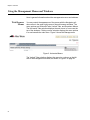
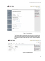

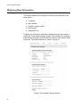
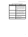


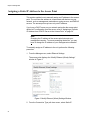


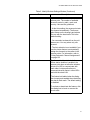

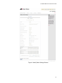


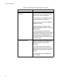


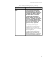


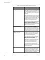
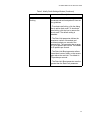
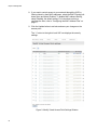
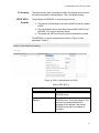

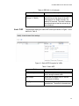
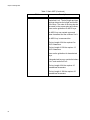
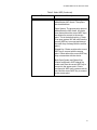
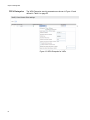
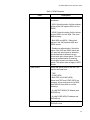

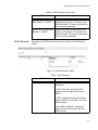

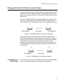
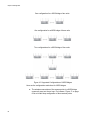
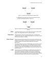
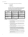
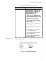
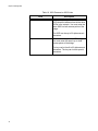
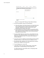

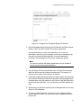

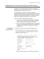


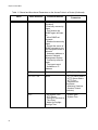
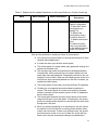
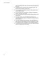
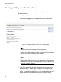
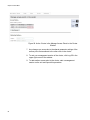


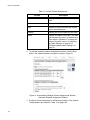


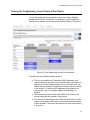
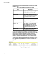
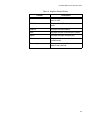

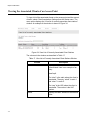


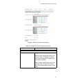

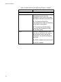
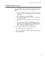
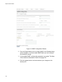
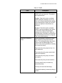
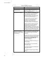
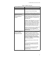

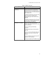
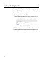
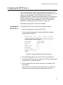


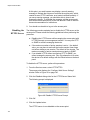
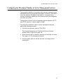


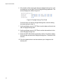
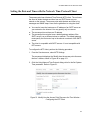


![Installation Guide: AT-TQ2450 [Rev A] (PDF Version)](http://vs1.manualzilla.com/store/data/005654085_1-f326a5d33793ff2ec849a19a13c1dba6-150x150.png)