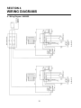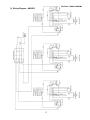
1
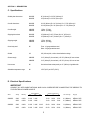
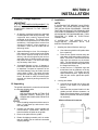
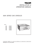
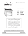
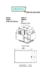
Toastmaster ® AM24SS AM24SS and AM36SS ™ Griddles OWNER'S OPERATING & INSTALLATION MANUAL Toastmaster® A Middleby Company Middleby Cooking Systems Group • 1400 Toastmaster Drive • Elgin, IL 60120 • (847)741-3300 • FAX (847)741-4406 Part No. 37813 Price $15.00 P Apr. 98 Rev B NO QUIBBLE LIMITED WARRANTY TOASTMASTER, HEREINAFTER REFERRED TO AS THE SELLER, WARRANTS EQUIPMENT MANUFACTURED BY IT TO BE FREE FROM DEFECTS IN MATERIAL AND WORKMANSHIP FOR WHICH IT IS RESPONSIBLE. THE SELLER’S OBLIGATION UNDER THIS WARRANTY SHALL BE LIMITED TO REPLACING OR REPAIRING, AT SELLER’S OPTION, WITHOUT CHARGE, ANY PART FOUND TO BE DEFECTIVE AND ANY LABOR AND MATERIAL EXPENSE INCURRED BY SELLER IN REPLACING OR REPAIRING SUCH PART. SUCH WARRANTY SHALL BE LIMITED TO THE ORIGINAL PURCHASER ONLY AND SHALL BE EFFECTIVE FOR A PERIOD OF ONE YEAR FROM DATE OF ORIGINAL INSTALLATION, OR 18 MONTHS FROM DATE OF PURCHASE, WHICHEVER IS EARLIER; PROVIDED THAT TERMS OF PAYMENT HAVE BEEN FULLY MET. As part of Toastmasters “no quibble” warranty, all in-warranty Toastmaster products that require service, are to be serviced on site. The warranty period for Accu-Miser griddles shall be 24 months from the date of installation or 30 months from the date of purchase, whichever is earlier. Normal maintenance functions, including lubrication, cleaning, or customer abuse, are not covered by this “no quibble” warranty. Seller shall be responsible only for repairs or replacements of defective parts performed by Seller’s authorized service personnel. Authorized service agencies are located in principal cities throughout the contiguous United States, Alaska, and Hawaii. This warranty is valid in the 50 United States and is void elsewhere unless the product is purchased through Middleby International with warranty included. The foregoing warranty is exclusive and in lieu of all other warranties, expressed or implied. There are no implied warranties of merchantability or of fitness for a particular purpose. The foregoing shall be Seller’s sole and exclusive obligation and Buyer’s sole and exclusive remedy for any action including breach of contract or negligence. In no event shall Seller be liable for a sum in excess of the purchase price of the item. Seller shall not be liable for any prospective or lost profits of Buyer. © 1998 Toastmaster, A Middleby Company is a registered trademark of Toastmaster, A Middleby Company. ™ is a trademark of Toastmaster, A Middleby Company. Toastmaster • 1400 Toastmaster Dr. • Elgin, IL 60120-9272 • (847) 741-3300 • FAX (847) 741-4406 Middleby Corp 24-Hour Service Hotline 1-800-238-8444 i WARNING: IN CASE OF FIRE Disconnect the griddle from its power source IMMEDIATELY. Shutting down the electrical heating elements allows the unit to cool, making it easier to put out the fire. WARNING: FOR YOUR SAFETY DO NOT STORE OR USE GASOLINE OR OTHER FLAMMABLE VAPORS OR LIQUIDS IN THE VICINITY OF THIS OR ANY OTHER APPLIANCE CAUTION Use only a fire extinguisher filled with CO2, which is suitable for electrically powered equipment. Do NOT attempt to fight a grease fire by aiming the nozzle of the fire extinguisher directly at the burning grease. The force will cause the burning grease to be sprayed to adjoining equipment, making it difficult to contain the fire. CAUTION Using any parts other than genuine Toastmaster factory parts relieves the manufacturer of all liability. IMPORTANT Toastmaster (manufacturer) reserves the right to change specifications and product design without notice. Such revisions do not entitle the buyer to corresponding changes, improvements, additions or replacements for previously purchased equipment. RETAIN THIS MANUAL FOR FUTURE REFERENCE This manual provides detailed information for installation and operation of your Accu-Miser griddle. It also contains information to assist the operator in diagnosing problems in the event of a malfunction. This manual is an important tool for the operator and should be kept readily available. ii TABLE OF CONTENTS SECTION 1 DESCRIPTION............................................................................................................................................... 1 A. Features.............................................................................................................................................1 B. Component Location..........................................................................................................................1 C. Specifications.....................................................................................................................................2 D. Electrical Specifications..................................................................................................................... 2 E. Dimensional Drawings....................................................................................................................... 3 SECTION 2 INSTALLATION.............................................................................................................................................. 5 A. Shipping Damage Inspection............................................................................................................. 5 B. Unpacking the Griddle....................................................................................................................... 5 C. Installation..........................................................................................................................................5 D. Electrical Connection......................................................................................................................... 6 E. Initial Cleaning................................................................................................................................... 6 F. Testing the Installation....................................................................................................................... 6 SECTION 3 OPERATION...................................................................................................................................................7 A. Controls..............................................................................................................................................7 B. Seasoning the Griddle....................................................................................................................... 7 C. Operating Hints and Safety................................................................................................................ 7 D. Daily Operation and Maintenance......................................................................................................8 E. Troubleshooting................................................................................................................................. 9 SECTION 4 WIRING DIAGRAMS...................................................................................................................................... 10 A. Wiring Diagram - AM24SS................................................................................................................. 10 B. Wiring Diagram - AM36SS................................................................................................................. 11 iii SECTION 1 DESCRIPTION A. Features Models: • AM24SS, 24” (610mm) wide, two 12” (305mm) infrared heat panels • AM36SS, 36” (914mm) wide, three 12” (305mm) infrared heat panels Accu-Miser Series SS griddles are: • Electrically heated by infrared emitter panels • Temperature-controlled by solid-state thermostat • Counter-top mounted The Accu-Miser griddle employs infrared cooking technology. Infrared heat panels are located below the griddle plate. Each panel is 12” (305mm) in width, and provides uniform heat distribution across its surface. A thermostatic solid-state controller for each panel accurately maintains the set griddle cooking temperatures for consistent and repeatable results. Each thermostat has a range of 150°F (83°C) to 450°F (232°C). The individual controls and thermostat allow independent temperature settings for each panel. This feature divides the griddle plate into 12” (305mm)-wide zones that can cook different food products simultaneously. B. Component Location Splash Guard Grease Chute (rear) Griddle Plate Grease Chute (front) Grease Trough (rear) Grease Trough (front) Thermostat Control Knob Heating Indicator Light Spacer bracket (2) On/Off Switch Grease Drawer 4” (102mm) legs (4) (countertop griddles only) (AM24SS shown) 1 SECTION 1 - DESCRIPTION C. Specifications Griddle plate dimensions AM24SS AM36SS 24” (610mm) D x 23-7/8” (606mm) W 24” (610mm) D x 35-7/8” (911mm) W Overall dimensions AM24SS AM36SS 32-1/8” (816mm) D x 24” (610mm) W x 17-7/8” (454mm) H 32-1/8” (816mm) D x 36” (914mm) W x 17-7/8” (454mm) H Overall weight AM24SS AM36SS 170 lbs. (77.2kg) 244 lbs. (110.8kg) Shipping dimensions AM24SS AM36SS 33” (838mm) D x 29” (737mm) W x 18” (457mm) H 33” (838mm) D x 40” (1016mm) W x 17” (432mm) H Shipping weight AM24SS AM36SS 177 lbs. (80.4kg) 254 lbs. (115.3kg) Outer body steel All Front: 16-gauge stainless steel Sides: 20-gauge stainless steel Griddle All 3/8” (9.5mm) thick, uniform heat distribution design Grease trough AM24SS AM36SS 3-1/2” (89mm) D (front-to-back) x 23-7/8” (606mm) W, front and rear 3-1/2” (89mm) D (front-to-back) x 35-7/8” (911mm) W, front and rear Heat source All One infrared heat emitter panel per 12” (305mm) of griddle width Allowable temperature range All 150°F (83°C) to 450°F (232°C) D. Electrical Specifications IMPORTANT CONSULT ALL APPLICABLE NATIONAL AND LOCAL CODES BEFORE CONNECTING THE GRIDDLE TO ITS ELECTRICAL POWER SOURCE. Loading kW/phase Nominal current/line wire Model Voltage kW rating X-Y Y-Z X-Z X Y Z Pwr. cord length Plug type AM24SS 208V 240V 6.2kW 6.2kW 3.1kW 3.1kW 3.1kW 3.1kW - 15.0A 13.0A 26.0A 22.5A 15.0A 13.0A 6’ (1829mm) 6’ (1829mm) NEMA 15-50P NEMA 15-50P AM36SS 208V 240V 9.4kW 9.4kW 3.1kW 3.1kW 3.1kW 3.1kW 26.0A 22.5A 26.0A 22.5A 26.0A 22.5A 6’ (1829mm) 6’ (1829mm) NEMA 15-50P NEMA 15-50P 3.1kW 3.1kW 2 E. Dimensional Drawings SECTION 1 - DESCRIPTION 3 SECTION 1 - DESCRIPTION NOTES 4 SECTION 2 INSTALLATION A. Shipping Damage Inspection C. Installation IMPORTANT NOTE IT IS THE CUSTOMER’S RESPONSIBILITY TO REPORT ANY CONCEALED OR NONCONCEALED DAMAGE TO THE FREIGHT COMPANY. IF INSTALLING THE GRIDDLE ON A STAND, CONSULT THE STAND INSTRUCTIONS FOR THE INSTALLATION PROCEDURE. ENSURE THAT THE LOCATION OF THE STAND ALLOWS SUFFICIENT CLEARANCE FOR THE GRIDDLE, AS SHOWN IN THE DIAGRAM BELOW. THEN, PROCEED TO STEP D, ELECTRICAL CONNECTION. 1. All shipping containers should be examined for damage before and during unloading. This equipment was carefully inspected and packaged at the factory. The freight carrier has assumed responsibility for its safe transit and delivery. If the equipment is received in a damaged condition, either apparent or concealed, a claim must be made with the delivering carrier. IF INSTALLING THE GRIDDLE ON A COUNTERTOP, PROCEED WITH THE INSTRUCTIONS BELOW. 1. Installing the Spacer Brackets and Legs a. Check that the griddle is still upside-down from unpacking. 2. Apparent Damage or Loss - If the damage or loss is apparent, it must be noted on the freight bill or on the express receipt at the time of delivery, and must be signed by the carrier’s agent (the driver). If this is not done, the carrier may refuse the claim. The carrier will supply any necessary claim forms. b. Place the two spacer brackets along the side edges of the bottom plate of the AccuMiser. The holes in the brackets should align with the weldnuts on the bottom plate. The flanged edge of the brackets should face the outside of the griddle, with the flange itself facing up. 3. Concealed Damage or Loss - If damage or loss is NOT apparent until after the equipment is unpacked, a request for inspection of the concealed damage must be made with the carrier within 15 days. The carrier will make an inspection and will supply necessary claim forms. Be certain to retain all contents plus external and internal packing materials for inspection. c. Locate the four 4” adjustable legs and thread them into the weldnuts on the leg mounting plates. This holds the two spacer brackets in place. Tighten the legs until they are secure against the spacer brackets. 2. Leveling the Griddle B. Unpacking a. Carefully lift the griddle onto its legs, and place it on the counter in its permanent position. The griddle is delivered in a carton that is fastened to a wooden shipping pallet. b. Check that the proposed location for the griddle provides sufficient clearance, as shown in the diagram below. If not enough clearance is provided, relocate the griddle as necessary. WARNING USE CAUTION WHEN CUTTING THE BANDING STRAPS. WHEN CUT, THE STRAPS MAY SNAP AWAY FROM THE CARTON. Minimum External Clearances 1. Cut the banding straps that hold the carton in place. Lift the carton up, and remove it from over the griddle. 2. Carefully turn the pallet - with the griddle still mounted atop it - upside-down. Remove the bolts that fasten the pallet to the griddle. 3. Remove the pallet from the griddle. 4. Retain all shipping materials until it is certain that the griddle has not suffered concealed shipping damage. 5 SECTION 2 - INSTALLATION c. Level the griddle using a carpenter’s level. Then, rotate the “foot” (hexagonal) portion of the legs to adjust the griddle to a level position. 1. The surface of the griddle plate is coated with a rust-preventive material to protect it during shipment. Clean this material from the griddle plate with a non-flammable grease solvent. d. Ensure that the griddle is level from frontto-back and from side-to-side. 2. Wash the griddle with warm water and a mild detergent. 3. Rinse with a damp cloth, then wipe the griddle dry. D. Electrical Connection 4. Ensure that the griddle is completely dry before restoring electrical power to the unit. All Accu-Miser Series SS griddles come factoryequipped with a power cord and plug. The chart below shows the plug type for each griddle model. Model AM24SS AM36SS F. Testing the Installation Plug type NEMA 15-50P NEMA 15-50P IMPORTANT BEFORE TESTING THE INSTALLATION, FAMILIARIZE YOURSELF WITH THE ACCUMISER OPERATING CONTROLS (SECTION 3A). IMPORTANT THE ELECTRICAL CONNECTION TO THE ACCU-MISER REQUIRES A CIRCUIT BREAKER/ FUSED DISCONNECT. THE REQUIRED RATING OF THE BREAKER VARIES ACCORDING TO THE MODEL OF GRIDDLE BEING INSTALLED. REFER TO THE GRIDDLE’S DATA PLATE, AND TO THE ELECTRICAL SPECIFICATIONS TABLE (PAGE 2). 1. Ensure that the initial cleaning of the griddle has been performed, as outlined in Step E above. 2. Turn all rocker ON/OFF switches to the OFF position. 3. Rotate all thermostat control knobs counterclockwise to their lowest temperature setting. CONSULT ALL APPLICABLE NATIONAL AND LOCAL CODES FOR FURTHER ELECTRICAL CONNECTION REQUIREMENTS. 4. Switch on the circuit breaker/fused disconnect. 1. Before proceeding with the electrical connections, check the following: 5. Perform the following steps for each set of controls (2 sets for AM24SS, 3 sets for AM36SS). If any of these tests fail, contact your Authorized Service Agent. a. Check that the supply wire size is adequate. b. Check that the circuit breaker/fused disconnect is present, and of the correct rating. a. Switch the rocker ON/OFF switch to the ON position. b. Rotate the thermostat control knob clockwise to a setting of 200°F (93°C). If necessary, refer to the griddle’s data plate and to the Electrical Specifications table (Page 2). c. WARNING ENSURE THAT THE CIRCUIT BREAKER/FUSED DISCONNECT IS IN THE “OFF” POSITION BEFORE PROCEEDING. Check that the heating indicator light located beneath the thermostat control knob illuminates. d. Wait for a few minutes; then, check that the zone of the griddle plate that corresponds to the controls has begun to heat. 2. Insert the power cord plug into its receptacle. e. Wait for a few minutes to check that the heating indicator light turns off, showing that the zone has reached the proper temperature. E. Initial Cleaning WARNING ENSURE THAT ELECTRICAL POWER TO THE GRIDDLE HAS BEEN DISCONNECTED BEFORE CLEANING THE UNIT. f. 6 Rotate the thermostat control knob back to its lowest setting. Switch the rocker ON/ OFF switch to OFF. SECTION 3 OPERATION WARNING A. Controls NEVER TOUCH AN OPERATING GRIDDLE. ALWAYS WAIT UNTIL ALL ON/OFF SWITCHES HAVE BEEN SET TO “OFF” FOR AT LEAST 30 MINUTES. This section provides a basic description of the location and function of the griddle operating controls (all located on the control panel). Refer to the diagram below. 4. Turn all Thermostat Control Knobs to 0 (off). Switch the On/Off Switches to “Off.” 1. Thermostat Control Knob : Adjusts the corresponding griddle zone to new temperature requirements. The maximum set point is 450°F (232°C), and the minimum is 150°F (65°C). 5. Wait at least 30 minutes for the griddle to cool, then wipe off the excess oil with clean cloths. 6. Switch the On/Off Switches to “On.” Set the Thermostat Control Knobs to 350°F (175°C). 2. Heating Indicator Light: Each heating indicator light is illuminated whenever the corresponding griddle zone is calling for heat. The light turns off when the griddle section has reached the temperature set on the thermostat control knob. 7. Repeat Steps 1, 3, 4, and 5. This completes the griddle “seasoning.” 8. Switch the On/Off Switches to “On.” Set the Thermostat Control Knobs to the proper temperature setting(s) for the type of food to be cooked. After the Heating Indicator Lights turn off, the griddle is ready for use. 3. On/Off Switch: Turns the corresponding griddle zone on and off. C. Operating Hints and Safety Griddle Operating Controls Although the finest materials, engineering planning, and manufacturing facilities have provided for safe and trouble-free operation, only proper use and maintenance will assure personnel safety and long life for your Accu-Miser griddle. The following are a few precautions and operating suggestions for use of the griddle. 1. Disconnect power to the griddle at the breaker/ fused disconnect at the end of each day of operation. Thermostat Control Knob 2. NEVER leave the griddle in operation without an attendant. 3. NEVER operate the griddle without the grease drawer FULLY in place. Heating Indicator Light 4. Turn the thermostat control knobs down to a “standby” temperature of 200°F (93°C) during idle periods. Leaving the griddle to idle at high tempertures can cause food particles and grease film to carbonize. It takes only a few minutes to regain operating temperatures. On/Off Switch B. Seasoning the Griddle 1. Spread a light film of unsalted cooking oil over the entire griddle surface with a soft cloth. 2. Set all Thermostat Control Knobs to 300°F (149°C). 3. Allow the griddle to operate for at least two minutes. This allows the oil to work into the pores of the metal, forming a smooth coating over the exterior surface of the griddle. Use a spatula to spread the oil, if necessary. 7 5. Do not heat the entire griddle for cooking small amounts of food. Any zones not required for cooking can be left at the “standby” temperature. 6. Various kinds of food can be cooked at the same time by setting each zone of the griddle to a different temperature. 7. Use a spatula to push excess grease into the grease troughs after each load of food is cooked. This reduces smoking and carbonizing of hot grease. SECTION 3 - OPERATION D. Daily Operation And Maintenance Daily Pre-Operation 2. Cleaning the exterior 1. Season the griddle before operation daily as described in Step B, Seasoning the Griddle. a. Wipe down the sides of the griddle, and all areas around the griddle, with a damp towel to remove accumulated splashed grease. 2. Always allow 15 minutes of preheat time before loading the griddle with food. This will allow the griddle surface to be saturated with heat. Failure to allow sufficient preheat time will result in unsatisfactory cooking of the first load. b. Remove any remaining grease with warm water and a mild detergent. DO NOT apply enough liquid to stand in place on the unit. Daily Post-Operation c. Cleaning the griddle on a daily basis, as outlined below, greatly lessens the formation of hard-toremove grease stains that can affect food quality. d. Polish the griddle with a dry, soft cloth. 3. Cleaning the grease drawer, chutes, and troughs WARNING DISCONNECT ELECTRICAL POWER AT THE BREAKER/FUSED DISCONNECT BEFORE ATTEMPTING TO CLEAN THE ACCU-MISER. a. Empty the grease drawer as often as necessary, but it MUST be emptied at the end of each day of operation, or at the end of each shift. WARNING Wash out the grease drawer with hot water and a mild detergent. Wipe it dry and replace it in the griddle. WHEN CLEANING THE ACCU-MISER, NEVER ALLOW WATER TO STAND IN PLACE ON THE UNIT. EXCESSIVE MOISTURE INSIDE THE UNIT WILL CAUSE A SEVERE ELECTRICAL HAZARD, AND MAY OTHERWISE DAMAGE THE GRIDDLE. b. At the end of each shift or day of operation, thoroughly clean the grease troughs and grease chutes. 1. Cleaning the Griddle Surface a. To provide evenly cooked and perfectly browned foods, keep the griddle surface free of carbonized grease. Carbonized grease on the griddle surface hinders the transfer of heat from the griddle surface to the food. This results in spotty browning, and a loss of cooking efficiency. Carbonized grease also tends to cling to the griddled foods, giving them a highly unsatisfactory and unappetizing appearance. b. Clean the surface of the griddle plate with a pumice or griddle stone by rubbing with the grain of the metal while the griddle surface is still warm. c. Wipe the griddle dry with a clean towel. Ensure that all visible moisture has been removed. Wipe the griddle clean of residue from the griddle stone. 8 SECTION 3 - OPERATION E. Troubleshooting Problem Action Griddle is not heating. 1. Check that the breaker/fused disconnect is in the ON position. Griddle zone is not heating. 1. Check that the corresponding rocker switch is turned on. 2. Check that the thermostat is set to the proper temperature. If problems persist, contact your local Authorized Service Agent. 9 SECTION 4 WIRING DIAGRAMS A. Wiring Diagram - AM24SS 10 SECTION 4 - WIRING DIAGRAMS B. Wiring Diagram - AM36SS 11 For more information on the complete line of Toastmaster products, contact your Food Service Equipment Dealer, or write to us at the address below. A Middleby Company Middleby Corp 24-Hour Service Hotline 1-800-238-8444 Toastmaster 1400 Toastmaster Drive Elgin, IL 60120 (847)741-3300 FAX (847)741-4406