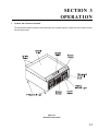
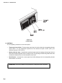
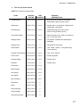
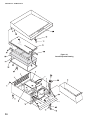
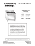
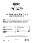
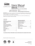
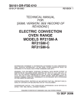
1
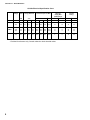
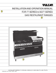
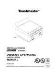
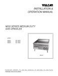
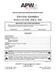
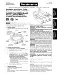
Toastmaster
®
A Middleby Company
OWNER'S OPERATING
& INSTALLATION
MANUAL
AM24, AM36 & AM48
ACCU-MISER GRIDDLES
AM24
Toastmaster® • 1400 Toastmaster Drive • Elgin, IL 60120 • (708)741-3300 • FAX (708)741-4406
A Middleby Company
Middleby Corp 24 Hour Service Hotline 1-800-238-8444
Part No. 32025
Price $15.00
P 2/95
Toastmaster
®
GRIDDLE LIMITED WARRANTY
All equipment manufactured by Toastmaster Commercial which is sold under the “Toastmaster” trademark and used for commercial purposes is warranted against defects in
materials and workmanship. The warranty period runs 12 months from the original date of
installation. This 12 month warranty period may not run beyond 18 months from the original
date of purchase and is for the benefit of the original purchaser only. ALL OTHER
WARRANTIES, EXPRESS OR IMPLIED, STATUTORY OR OTHERWISE, INCLUDING
WITHOUT LIMITATION ANY IMPLIED WARRANTY OR MERCHANTABILITY OR FITNESS FOR PURPOSE ARE EXCLUDED. Seller shall in no event be liable for direct,
indirect or consequential damages in connection with Toastmaster Commercial products.
Seller’s obligation under this warranty is limited to the repair of defects without charge, by
a factory authorized service agency or one of its sub-service agencies. Such repair service
will be provided on customer’s premises except in the case of portable products.
Models that are considered portable (devices with cord and plugs) including conveyor
toasters must be taken or shipped to the closest authorized service agency, transportation
charges prepaid.
This warranty is not effective if damage occurs because of accident, carelessness,
improper installation, lack of proper set-up supervision when required or because
equipment is installed on a different voltage, steam or gas service then designated on the
equipment nameplate, or if the equipment is installed or operated in any manner contrary
to the installation and operation instructions. In these cases, repairs will be made at a
reasonable cost. Work performed by unauthorized personnel or service agencies voids
this warranty.
Authorized service agencies are located in principal cities throughout the world. Please
consult your classified telephone directory, your food service equipment distributor, or
write the Factory Service Department, Toastmaster®, 1400 Toastmaster Drive, Elgin,
Illinois 60120, for information and other details concerning service of this warranty.
© 1995 Toastmaster
Toastmaster • 1400 Toastmaster Dr. • Elgin, IL 60120-9272 • (708) 741-3300 • FAX (708) 741-4406
Middleby Corp 24 Hour Service Hotline 1-800-238-8444
i
IN CASE OF FIRE
1. De-energize griddle at disconnect switch. This will cut off power to the heating elements allowing
griddle to cool. This reduces the flash point temperature making it easier to stop the fire.
2. Cover the affected area with a heavy blanket or canvas. Play the fire extinguisher nozzle over the
blanket or cover to seal off air thus smothering the fire.
CAUTION:
Do not attempt to fight a grease fire by playing the nozzle of the fire extinguisher directly on the
burning grease. The force will cause the burning grease to be sprayed to adjoining equipment
making it difficult to contain the fire. Only use a fire extinguisher filled with CO2 which is for liquids
and oils and suitable for electric powered equipment.
RETAIN THIS MANUAL FOR FUTURE REFERENCE
This manual provides detailed information for installation and operation of your new Accu-Miser griddle.
It also contains some information to assist the operator in diagnosing problems in the event of a
malfunction. This manual is an important tool for the operator and should be kept readily available.
FOR YOUR SAFETY
DO NOT STORE OR USE GASOLINE
OR OTHER FLAMMABLE VAPORS OR LIQUIDS
IN THE VICINITY OF THIS OR ANY OTHER APPLIANCE
NOT ICE
Using any parts other than
genuine Toastmaster factory
parts relieves the
manufacturer of all liability.
NOT ICE
Toastmaster (Manufacturer) reserves the right
to change specifications and product design
without notice. Such revisions do not entitle
the buyer to corresponding changes, improvements, additions or replacements for
previously purchased equipment.
ii
TABLE OF CONTENTS
SECTION 1
DESCRIPTION
........................................................................................ 1
Component Location ................................................................................. 2
Specification Chart .................................................................................... 3
Electrical Specification Chart ..................................................................... 4
Dimension Drawing ................................................................................... 5
SECTION 2
INSTALLATION
........................................................................................ 7
A. Inspect For Shipping Damage .............................................................. 7
B. Unpacking Griddle ................................................................................ 7
C. Installing Griddle on Counter ................................................................ 7
D. Installing Griddle on Accessory Stand .................................................. 8
E. Electrical Connection ............................................................................ 10
F. Initially Clean the Griddle ...................................................................... 11
G. Test the Installation .............................................................................. 11
SECTION 3
OPERATION
........................................................................................ 13
Location and Function of Controls ............................................................. 13
A. Controls ........................................................................................ 14
B. Seasoning the Griddle .................................................................... 15
C. Operating Hints and Safety ............................................................ 15
D. Daily Operation and Maintenance .................................................. 15
E. Operation Troubleshooting ............................................................. 16
F. Time and Temperature Guide ......................................................... 17
G. Cooking Capacities ........................................................................ 18
SECTION 4
PARTS LIST
........................................................................................ 19
Overall Parts List ....................................................................................... 20
SECTION 5
ELECTRICAL SCHEMATIC ............................................................................ 23
AM24 Wiring Diagram & Schematic .......................................................... 24
AM36 Wiring Diagram & Schematic .......................................................... 26
AM48 Wiring Diagram & Schematic .......................................................... 28
iii
SECTION 1 - DESCRIPTION
SECTION 1
DESCRIPTION
ACCU-MISER (AM) SERIES GRIDDLES ARE:
• Electrically heated
• Counter top mounted
• Heated by infrared emitter panels
• Thermostat solid state controller
MODELS:
• AM24 (24" wide)
• AM36 (36" wide)
• AM48 (48" wide)
INFRARED HEAT PANELS.
The griddle employs infrared cooking technology. Infrared heat panels are placed below the griddle plate. These
panels are 12" wide, which means an AM24 will accommodate 2 panels, an AM36 will accommodate 3 panels and
etc. A thermostatic solid state controller for each 12" zone accurately maintains set griddle cooking temperatures for
consistent and repeatable results. The thermostats have a range of 150°F (83°C) to 450°F (232°C). The griddle
provides uniform heat distribution across the griddle surface.
FEATURES:
• Griddle On/Off switch.
• Thermostat Control with Heating Indicator Light (Red).
• The griddle features stainless steel front, sides and back.
• The griddle is equipped with a grease trough and a large grease drawer.
• The Toastmaster® AM Series Griddles are supplied with four 4" adjustable legs.
IMPORTANT!: For all installations the legs or the optional stand must be used to validate the warranty.
Figure 1-1
1
SECTION 1 - DESCRIPTION
Component Location
Figure 1-2
2
SECTION 1 - DESCRIPTION
NOTICE
Toastmaster (Manufacturer) reserves the right to change specifications and product design
without notice. Such revisions do not entitle the buyer to corresponding changes, improvements, additions or replacements for previously purchased equipment.
AM Series Griddles Specification Chart
Griddle Plate Dimensions -
AM24
23-7/8" (606 mm) W x 24" (610 mm) D
AM36
35-7/8" (911 mm) W x 24" (610 mm) D
AM48
47-3/4" (1213 mm) W x 24" (610 mm) D
AM24
24" (610 mm)W x
28-1/2" (724 mm)D x 15" (381 mm)H
AM36
36" (914 mm)W x
28-1/2" (724 mm)D x 15" (381 mm) H
AM48
47-15/16" (1218 mm)W x
28-1/2" (724 mm)D x 15" (381 mm) H
Net Weight -
AM24
AM36
AM48
120 lbs. (54 kgm)
222 lbs. (101 kgm)
275 lbs. 125 kgm)
Shipping Weight -
AM24
AM36
AM48
140 lbs. (63 kgm)
242 lbs. (110 kgm)
300 lbs. (136 kgm)
Shipping Dimensions -
AM24
28-1/2" (724 mm)W x
33-1/2" (851 mm)D x 17-1/2" (445 mm)H
AM36
40-1/2" (1029 mm)W x
33" (838 mm)D x 16-1/2" (419 mm) H
AM48
52-1/2" (1334 mm)W x
31-1/2" (800 mm)D x 16-1/2" (419 mm) H
Overall Dimensions -
Average Operating kw
Allowable Temperature Ranges
Heat Source
Griddle
Grease Trough
Outer Body Steel
Refer to Electrical Data Chart on following page
150°F (83°C) to 450°F (232°C)
Infrared heat emitter panels
One 12" emitter panel for each 12" of griddle width
3/8" thick, uniform heat distribution design
3-1/2"
Front, 16 gauge stainless steel
Sides, 20 gauge stainless steel
3
SECTION 1 - DESCRIPTION
Griddle Electrical Specification Chart
Voltage
Total
Loading kW/Phase
kW
Nominal Amps/Line Wire
3 Ph
3 Ph
X-Y
Y-Z
X-Z
X
Y
Z
Minimum
Supply Wire
(AWG) Gauge*
1 Ph
3 Ph
1 Ph
3 Ph
1 Ph
AM24
208
240
6.2
6.2
3.1
3.1
3.1
3.1
---
15.0
13.0
26.0
22.5
15.0
13.0
30.0
26.0
10
10
8
10
25
30
30
30
AM36
208
240
9.3
9.3
3.1
3.1
3.1
3.1
3.1
3.1
26.0
22.5
26.0
22.5
26.0
22.5
45.0
39.0
10
10
6
8
25
30
40
45
AM48
208
240
12.5
12.5
6.2
6.2
3.1
3.1
3.1
3.1
39.7
35.9
39.7
35.9
26.0
22.5
60.1
52.0
8
8
4
6
35
40
50
60
* Provided for reference only. Consult national or local electrical codes.
4
Breaker
Rating*
SECTION 1 - DESCRIPTION
Griddle Dimension Drawing
5
SECTION 1 - DESCRIPTION
NOTES
6
SECTION 2 - INSTALLATION
SECTION 2
INSTALLATION
A. Inspect for Shipping Damage
All shipping containers should be examined for damage before and during unloading. This equipment
was carefully inspected and packaged at the factory.
The freight carrier has assumed responsibility for its
safe transit and delivery. If equipment is received in
damaged condition, either apparent or concealed, a
claim must be made with the delivering carrier.
1. Apparent Damage or Loss - If damage or loss is
apparent it must be noted on the freight bill or
express receipt at the time of delivery, and it must be
signed by the carrier’s agent (driver). If this is not
done, the carrier may refuse the claim. The carrier
will supply the necessary claim forms.
2. Concealed Damage or Loss - If damage or loss
is NOT apparent until after equipment is uncrated, a
request for inspection of concealed damage must be
made with carrier within 15 days. The carrier will
make an inspection and will supply necessary claim
forms. Be certain to retain all contents plus external
and internal packaging/crating materials for inspection.
B. Unpacking Griddle
1. The griddle will be delivered in a carton on a wooden
pallet. Cut the banding straps that hold the carton in place
and lift the carton up and off of the griddle.
2. Carefully turn the griddle upside down and remove the
bolts that secure the pallet to the griddle.
Remove the pallet and discard.
C. Installing Griddle on Counter.
NOTE: If you are installing the griddle on an accessory
stand go to Step D.
1. Installing Legs
Locate the four NSF approved 4" adjustable legs in the
grease drawer.
With the grill still turned upside down install the four legs
by threading them into the weldnuts on the leg mounting
plates. Tighten the legs securely.
2. Leveling Griddle
Carefully lift the griddle onto its legs and place it on the
counter in its permanent position. Level the griddle using
a common carpenters level. Adjust the foot portion of the
adjustable legs to level the griddle front-to-back and sideto-side.
7
SECTION 2 - INSTALLATION
D. Installing Griddle on Accessory Stand.
NOTE: If you are installing the griddle on a counter do not do Step D. Go directly to Step E.
Accessory stands are available for all Accu-Miser Griddles. See the following Accessory Stand List.
GRIDDLE ACCESSORY STAND LIST
Griddle
Model Number
Accessory
Number
AM24
AM36
AM48
All Models
7324ES
7336ES
7348ES
ACCS06J
Description
Stand. Mount on 6" casters not included.
Stand. Mount on 6" casters not included.
Stand. Mount on 6" casters not included.
Casters. Set of four, NSF approved, adds 6-1/4"
to height of unit. 2 locking casters and
2 non-locking casters.
Stand Assembly:
1. Unpack the stand which is made up of two sets of legs.
2. Assemble the casters into the legs. The casters without brakes are installed on the rear legs and the casters with
brakes are installed on the front legs.
Install the casters as follows (refer to Figure 2-1):
a. Before inserting the caster into the leg, snug the knurled knob until the caster fits snugly into leg tube.
b. Insert caster into leg.
c. Tighten main bolt located under caster 1 to 2 turns.
Figure 2-1
8
SECTION 2 - INSTALLATION
3. Turn stand right side up and secure to griddle with 3/8-16 bolts and lockwashers as shown in Figure 2-2.
NOTE: Be sure the casters with brakes are located at the front of the griddle.
Figure 2-2
9
SECTION 2 - INSTALLATION
E. Electrical Connection
Be sure your electrician provides the proper wire gauge with a capacity for carrying the voltage required. Wire capacity
is listed on the serial number data plate. Wire capacity and electrical specifications are listed in Section 1 of this manual.
Also check local and state codes for proper wire size.
The incoming power wires from the circuit breaker box to the griddle are inserted into the rear or bottom of the griddle
as shown below.
The location of the main terminal block is shown below . For access to the terminal block remove the grease drawer,
open the door and then slide the drawer channel out as shown below. Connect the wires as shown on the electrical
schematic in Section 5 of this manual.
No internal fusing is provided on countertop griddles. Therefore the installing contractor must provide the proper
disconnect as may be required by state and local codes.
CAUTION:
Be sure the main power disconnect switch is in "OFF" position before
attempting to make any electrical connections.
Be sure all electrical connections are tight and are positioned so they will not short out.
IMPORTANT: All griddles are factory wired for 3 Ph and must be rewired during installation for 1 Ph connection. The
wiring for 1 Ph connection and 3 Ph connection for all models is shown on the Schematics in Section 5 of this manual.
Figure 2-3
10
SECTION 2 - INSTALLATION
F. Initially Clean the Griddle
1. Clean the rust preventive material from the griddle surface with a non-flammable grease solvent.
2. Wash the griddle with warm water and a mild detergent.
3. Rinse with a damp cloth and wipe dry.
G. Test the Installation, refer to Figure 3-2
NOTE: The griddle must be initially cleaned as directed in Step F before completion of Step G.
1. Turn all rocker On/Off switches to the "Off" position.
2. Turn all thermostat control knobs to the lowest temperature setting.
3. Turn the main power disconnect switch to "ON".
4. Turn "On" the On/Off switch located at the left end of the griddle. Then turn the corresponding left thermostat control
knob to 200°F (93°C) and check that heating light located below control knob illuminates. Wait a few minutes and check
to see if the left section of the griddle has heated. Then wait a few more minutes and check that the heating light goes
off when the section of the griddle reaches set temperature. Turn the temperature control knob back to its lowest
position and turn the On/Off Switch back to "Off".
5. Move to the next rocker On/Off switch and thermostat control knob and repeat Step 4. Continue until the entire
griddle has been tested.
11
SECTION 2 - INSTALLATION
NOTES:
12
SECTION 3 - OPERATION
SECTION 3
OPERATION
I.
Location and Function of Controls
The following information provides a basic description of the griddle operator components, their location and the
function they perform.
Figure 3-1
Operator Components
13
SECTION 3 - OPERATION
Figure 3-2
Control Panel
A. CONTROLS
All oven operating controls are on the control panel.
•
Thermostat Control Knob - The thermostat control knob is used to adjust the corresponding element
section above it to your temperature requirements. The maximum set point is 450°F (232°C), the
minimum set point is 150°F (65°C).
•
Heating Indicator Light - Located below each thermostat control the heating indicator light will be lit
whenever the adjacent griddle section is calling for heat. The light will go off when the griddle section has
reached the temperature set on the thermostat control knob.
•
On/Off Switch - Located on the control panel the On/Off switch(es) turn the corresponding element
section above it on and off.
IMPORTANT: Do not turn griddle on until procedures in Step B have been completed.
14
SECTION 3 - OPERATION
B. Seasoning the Griddle
1. Preheat the griddle to 300°F (149°C) and spread a light film of unsalted cooking oil or fat over the surface
with a soft cloth.
2. Allow griddle to stand this way for two minutes to give the oil an opportunity to work into the pores of the
metal and to form a smooth coating over the outside.
3. Wipe off excess oil and repeat Steps 1 and 2 at 350°F (175°C).
4. After the second step is completed wipe off excess cooking oil, set thermostat control knob for desired
temperature. The griddle is now ready for use.
C. Operating Hints and Safety
Although the finest materials, engineering planning and manufacturing facilities have provided for safety and
trouble-free operation only proper use and maintenance will assure personnel safety and long life of the
equipment. The following are a few precautions and operating suggestions for use of the griddle.
1. Disconnect power to the griddle at the disconnect switch at the end of each day of operation.
2. Do not leave griddle in operation without an attendant.
3. Turn thermostat dials down to 200°F (93°C) during idle periods. It takes only a few minutes to regain
operating temperatures.
4. Do not heat the entire griddle for cooking small amounts of food.
5. Various kinds of food can be cooked at the same time by setting each section of the griddle at different
temperatures.
6. Use a spatula to push excess grease into grease trough after each load of food is cooked. This will reduce
smoking of hot grease and carbonizing.
7. Do not leave griddle at high temperature when not in use or during idle periods. This will cause food particles
and grease film to carbonize.
D. Daily Operation And Maintenance
Daily Pre-Operation:
1. Season the griddle before operation daily as described in Step B above.
2. Always allow 15 minutes of preheat time before loading griddle with food. This will allow time for the griddle
surface to be saturated with heat. Failure to allow sufficient preheat time will result in unsatisfactory cooking
of the first load. The following chart indicates cooking time and temperature for various types of food.
Daily Post-Operation:
1. Cleaning the Griddle Surface
a. Good cooking requires clean equipment. To provide evenly cooked and perfectly browned foods, keep
the griddle surface free of carbonized grease. Carbonized grease on griddle surface hinders the transfer
of heat from the griddle surface to the food. This also results in spotty browning, loss of cooking efficiency,
and worst of all, carbonized grease tends to cling to the griddled foods, giving them a highly unsatisfactory
and unappetizing appearance.
15
SECTION 3 - OPERATION
b. At the end of each day of operation or at the end of each shift thoroughly clean the grease trough and
the spout into grease drawer.
c. Clean the griddle surface with a pumice or griddle stone by rubbing with the grain of the metal while
the griddle surface is still warm.
d. Wipe griddle clean of residue from the griddle stone
2. Cleaning the exterior - Wipe down sides of griddle and all areas around griddle to keep them free of
splashed grease.
a. Clean all surrounding surfaces of the griddle with warm water and a mild detergent daily.
b. Rinse and wipe off excess water.
c. Polish with a dry soft cloth.
NOTE: This simple treatment not only keeps the equipment dirt free and sparkling, it also eliminates the
danger of grease accumulation forming hard to remove stains.
3. Cleaning the grease drawer- Empty grease drawer as often as necessary, but be it must be emptied at
the end of each day of operation or the end of each shift. Also wash out grease drawer with hot water and a
mild detergent. Wipe dry and replace in griddle.
E. Operation Troubleshooting
1. Griddle not heating.
1. Check that incoming power electrical disconnect switch is turned on.
2. Griddle zone not heating.
2. Check that corresponding rocker switch is turned on.
Check that thermostat is set to proper temperature.
If unit still does not operate contact your local Toastmaster Service Representative.
16
SECTION 3 - OPERATION
F. Time and Temperature Guide
NOTE: All cooktimes are approximate.
FOOD
CONTROL
SETTING
TIME
IN MINUTES
ADVANCE
PREPARATIONS
Canadian Bacon
350°F(176°C)
3 to 4
Slice (not too far in advance as meat will
darken)-Split edges to prevent curling.
Hamburgers
350°F(176°C)
3 to 4
Prepare recipe - Form patties - Separate with
waxed paper - Refrigerate.
Cheeseburgers
350°F(176°C)
3 to 4
A hamburger patty plus melt a slice of
cheese on top just before serving.
Corned Beef Patties
375°F(190°C)
3 to 4
Open both ends of can - Slide out contents of
can - Cut into 3/8" slices.
Sausage Patties
350°F(176°C)
3 to 4
Form patties - Separate with waxed paper Refrigerate.
Sausage Links
350°F(176°C)
3
Potato Patties
375°F(190°C)
3 to 4
Cook - Mash - Season - Form patties using
1/4 cup measure.
American Fried Potatoes
375°F(190°C)
3 to 4
Cook - Slice - Season.
French Toast
400°F(204°C)
4 to 5
Prepare egg batter.
Scrambled Eggs
300°F(149°C)
3 to 4
Prepare recipe.
Pancakes
375°F(190°C)
2
Prepare recipe.
Frankfurters
375°F(190°C)
2 to 5
Minute Steaks
400°F(204°C)
3 to 4
Club Steaks
400°F(204°C)
3 to 5
Ham Steaks
400°F(204°C)
10
Beef Tenderloin
400°F(204°C)
5 to 7
Boiled Ham
375°F(190°C)
2
Bacon
350°F(176°C)
6
Hard Fried Eggs
300°F(149°C)
3
Soft Fried Eggs
300°F(149°C)
2
Sunny-Side-Up Eggs
300°F(149°C)
3
Refrigerate for best results.
17
SECTION 3 - OPERATION
G. Cooking Capacities
NOTE: All production capacities are approximate.
MODEL
LOAD CAPACITY
HAMBURGERS
18
CAPACITY PER HOUR
EGGS 4 "PANCAKES
HAMBURGERS
EGGS
4" PANCAKES
AM24
40
37
33
884
975
644
AM36
60
56
48
1326
1456
936
AM48
80
75
66
1768
1950
1287
SECTION 4 - PARTS LIST
SECTION 4
PARTS LIST
19
SECTION 4 - PARTS LIST
Figure 4-1
Overall Exploded Drawing
20
SECTION 4 - PARTS LIST
Parts List for
Figure 4-1
Overall Exploded Drawing
AM24
Item Qty
#
1
2
3
4
5
6
7
8
9
10
11
12
13
14
15
16
17
18
19
20
21
21
22
23
24
25
26
27
28
29
30
31
31
32
33
34
35
1
4
1
1
1
1
1
1
4
2
2
2
2
2
2
2
1
2
2
1
2
2
2
2
2
2
8
2
1
1
2
2
n/a
2
2
2
2
AM36
AM48
Part
#
Qty
Part
#
Qty
Part
#
30979
2000620
31183
30972
30977
30987
2700090
30976
3101908
31154
19A1S145
3003188
3A81D8801
3004290
3003993
97415
3003992
3004289
7007918
31160
7610644
7610831
7610637
2500132
7007920
31182
2002499
7007923
7007916
2001416
7610628
2500130
1
4
1
1
1
1
1
1
4
3
3
3
3
3
3
3
1
3
3
1
3
3
3
3
3
3
12
2
2
2
3
1
1
3
3
2
3
30988
2000620
31295
30987
30977
30987
2700090
30976
3101908
31154
19A1S145
3003188
3A81D8801
3004290
3003993
97415
3003992
3004289
7007918
31198
7610644
7610831
7610637
2500132
7007920
31182
2002499
7007923
7007916
2001416
7610628
2500130
2500133
4141A8803
31187
2001371
31646
1
4
1
1
1
1
1
1
4
4
4
4
4
4
4
4
1
4
4
1
4
4
4
4
4
4
16
2
3
3
4
n/a
2
4
4
2
4
30992
2000620
31210
30991
30977
30987
2700090
30976
3101908
31154
19A1S145
3003188
3A81D8801
3004290
3003993
97415
3003992
3004289
7007918
31207
7610644
7610831
7610637
2500132
7007920
31182
2002499
7007923
7007916
2001416
7610628
4141A8803
31187
2001371
31646
2500133
4141A8803
31187
2001371
31646
Description
Front Panel Assembly
Screw, #6 x 1/2 SHWHSM
Cover, Back
Cover, Bottom
Cover, Enclosure Assembly
Drawer Assembly
Gasket, Grease Spout
Enclosure
4" Adjustable Leg
Knob, Temp. Control
Switch, On/Off
Light
Tinnerman Clip
Controller w/Potentiometer
Terminal Block
Varistor
Power Terminal
Thermocouple
Bracket, Thermocouple
Griddle Plate Weldment
Heater Assembly, 208V
Heater Assembly, 240V
Frame Support, Heater Assembly
Insulation, 1-1/2" Thick
Stand-Off Package
Cover
Cotter, Hairpin
Shoulder Screw
Shoulder Screw
Nut
Support, Insul. Block Ass'y
Insulation, Short Strip
Insulation, Long Strip
Screw
Bracket, Pot
Nut
High Limit
21
SECTION 4 - PARTS LIST
NOTES:
22
SECTION 5 - SCHEMATICS
SECTION 5
SCHEMATICS
23
SECTION 5 - SCHEMATICS
24
SECTION 5 - SCHEMATICS
25
SECTION 5 - SCHEMATICS
26
SECTION 5 - SCHEMATICS
27
SECTION 5 - SCHEMATICS
28
SECTION 5 - SCHEMATICS
29
SECTION 5 - SCHEMATICS
For more information on the complete
line of Toastmaster® products, contact
your Food Service Equipment Dealer, or
write to us at the address below.
Toastmaster®
A Middleby Company
Middleby Corp 24 Hour Service Hotline 1-800-238-8444
Toastmaster®
1400 Toastmaster Drive
Elgin, IL 60120
(708)741-3300
Part No. 3102549
Price $15.00
Printed in U.S.A.
30