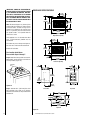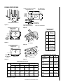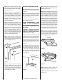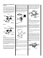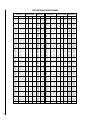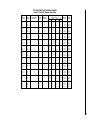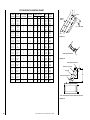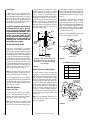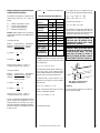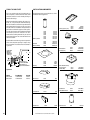
1
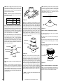
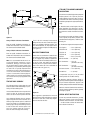
INSTALLATION
INSTRUCTIONS
CUSTOM SERIES
36" Wood Burning Fireplaces
P/N 700,024M REV. N/C 05/2004
MODELS
CR-3835R
CR-3835L
This installation manual will enable you to obtain a safe, efficient and
dependable installation of your fireplace system. Please read and understand these instructions before beginning your installation.
Do not alter or modify the fireplace or its components under any
circumstances. Any modification or alteration of the fireplace system,
including but not limited to the fireplace, chimney components and
accessories, may void the warranty, listings and approvals of this system
and could result in an unsafe and potentially dangerous installation.
IMPORTANT! TO ASSURE PROPER ALIGNMENT OF GLASS DOORS:
INSTALL THIS FIREPLACE IN A SQUARE AND PLUMB CONDITION,
USING SHIMS AS NECESSARY AT SIDES AND/OR BOTTOM.
PLEASE RETAIN THIS MANUAL FOR FUTURE REFERENCE.
RETAIN THESE INSTRUCTIONS
FOR FUTURE REFERENCE
OTL Report No. 116-F-20-4
NOTE: DIAGRAMS & ILLUSTRATIONS NOT TO SCALE.
1
TABLE OF CONTENTS
Safety Rules .................................... page
Tools and Building Supplies ............ page
Precautions ..................................... page
Introduction ..................................... page
Clearances/Height Requirements ..... page
Chimney System ............................. page
Assembly Outline ............................. page
Location of Fireplace ....................... page
Assembly Steps ............................... page
Preinstallation Notes ........................ page
Clearances ....................................... page
Installing the Fireplace ..................... page
Fireplace Specifications .................. page
Framing Specifications .................... page
Installing the Chimney System ........ page
30° Offset through Floor/Ceiling ...... page
Ten Foot Rule Summary .................. page
Multiple Terminations ...................... page
Chimney Component Calculations ... page
Special Offset Instructions ............... page
Offset Calculations ........................... page
Vertical Elevation Chart ................... page
Offset Elevation Chart ..................... page
Installing Offsets .............................. page
Combustion Air Kits ........................ page
Gas Line Connection ........................ page
Glass Doors ..................................... page
Cold Climate Insulation .................... page
Fireplace Finishes ............................ page
Mantels and Trim ............................. page
Hearth Extensions/Wall Shields ....... page
Finish Requirements ........................ page
Installation Components .................. page
2
2
2
3
3
3
4
4
5
5
5
5
6
7
8
9
11
11
11
11
12
13
15
17
17
17
18
18
18
18
18
20
20
IMPORTANT: PLEASE READ AND
UNDERSTAND THESE RULES TO
FOLLOW FOR SAFETY.
1. Before starting your fireplace installation,
read these installation instructions carefully to
be sure you understand them completely and in
entirety. Failure to follow them could cause a
fireplace malfunction resulting in serious injury
and/or property damage.
2. Always check your local building codes. The
installation must comply with all local, regional,
state and national codes and regulations.
2
3. These fireplaces must be installed with either
Security Chimneys model FTF8 (8" [203mm]
inside diameter) or FTF10 (10" [250mm] inside
diameter) Chimney System only. These systems are intended for use in any application
where a traditional masonry type fireplace would
apply. The chimney system must always vent to
the outside of the building.
4. To ensure a safe fireplace system and to prevent
the build-up of soot and creosote, inspect and
clean the fireplace and chimney prior to use and
periodically during the heating season.
5. Use solid fuel only. DO NOT use artificial
wax based logs, chemical chimney cleaners or
flame colorants in your fireplace.
6. DO NOT use charcoal or coal under any
circumstances.
7. NEVER use gasoline, gasoline-type lantern
fuel, kerosene, charcoal lighter fluid, or similar
liquids to start or “freshen up” a fire in this
fireplace. Keep any flammable liquids a safe
distance from the fireplace.
13. DO NOT use a fireplace insert or any other
products not specified herein by the manufacturer for use with this fireplace. All gas log sets
must be operated with the damper clamped
open, including unlisted “vent free” log sets.
Listed “vent-free” log sets may be operated
with the damper closed.
14. "Smoke free” operation is not warranteed
nor are we responsible for inadequate system
draft caused by mechanical systems, general
construction conditions, inadequate chimney
heights, adverse wind conditions and/or unusual environmental factors or conditions beyond our control.
15. Never, under any circumstances, install a
fireplace, chimney component or any accessories, that has visible or suspected physical
damage as a result of handling or transportation. These items should be inspected by your
distributor or qualified factory representative
to ensure safe condition. When in doubt, consult your distributor.
8. NEVER leave children unattended when
there is a fire burning in the fireplace.
16. For additional safety considerations and
complete operating instructions, refer to the
Care and Operation Manual provided with the
fireplace.
9. Always keep flue damper open when heat is
present in the fireplace.
TOOLS AND BUILDING SUPPLIES
NORMALLY REQUIRED
10. Before servicing, allow the fireplace to
cool. Always shut off any electricity or gas to
the fireplace while working on it. This will
prevent any possible electrical shock or burns.
Tools should Include:
Phillips screwdriver
Hammer
Saw and/or sabersaw
Level
Measuring tape
Plumb line
Electric drill and bits
Pliers
Square
11. This fireplace is not intended to heat an entire
home or be used as a primary heat source. It is
designed to ensure homeowner comfort by providing supplemental heat to the room.
12. Always ensure an that adequate supply of
replacement combustion air from the outside
of the house is accessible to the fire to support
normal combustion. Fireplaces consume large
volumes of air during the normal combustion
process. In the event the home is tightly sealed
with modern energy efficient features, the optional combustion air kit may not provide all
the air required to support combustion.
The manufacturer is not responsible for any
smoking or related problems that may result
from the lack of adequate combustion air. It is
the responsibility of the builder/contractor to
ensure that adequate combustion air has been
provided for the fireplace.
NOTE: DIAGRAMS & ILLUSTRATIONS NOT TO SCALE.
Building supplies:
Framing materials
Wall finishing materials
Caulking materials (noncombustible)
Fireplace surround and hearth
extension materials (noncombustible)
PRECAUTIONS
Note: These fireplace systems are not difficult
to install. However, in the interest of safety, it is
recommended that the installer be a qualified or
certified “tradesman” familiar with commonly
accepted fireplace installation and safety techniques as well as prevailing local codes.
The most important areas of concern dealing
with the installation of factory-built fireplaces are
clearances to combustible materials, proper assembly of component parts, height of the chimney system, the proper use of accessories supplied by the manufacturer and the techniques
employed in using finishing materials applied to
the wall surrounding the fireplace, hearth extensions and wall shields. Each of these topics will
be covered in thorough detail throughout this
manual. Please give each your special attention
as you progress with your installation.
INTRODUCTION
General Information
These fireplaces are conventional radiant heat
fireplaces with standard bar grates, optional
outside combustion air kits and optional decorative glass doors.
These fireplaces have been tested and listed by
Omni Test Labs (Report No.116-F-20-4) to
U.L. standard 127. These units are intended
for installation in residential homes and other
buildings of conventional construction including commercial, not in mobile homes.
Note: Illustrations shown reflect “typical”
installations with nominal dimensions and
are for design and framing reference only.
Actual installations may vary due to individual design preferences. However, always
maintain minimum clearances to combustible materials and do not violate any specific
installation requirements.
These fireplace systems are designed for installation in accordance with the National Fire
Protection Standard for chimneys, fireplaces
and solid fuel burning appliances; NFPA 211
and in accordance with codes such as the
BOCA Basic/National Codes, the Standard Mechanical Code and the Uniform Building Codes.
WARNING: FAILURE TO USE MANUFACTURE PROVIDED PARTS, VARIATIONS
IN TECHNIQUES AND CONSTRUCTION
MATERIALS OR PRACTICES OTHER THAN
THOSE DESCRIBED IN THIS MANUAL
MAY CREATE A FIRE HAZARD AND VOID
THE LIMITED WARRANTY.
When complete these fireplace systems consists of five basic “sub-systems”:
1.
2.
3.
4.
5.
The Fireplace
The Chimney and Termination
The Optional Glass Doors
The Optional Combustion Air Kits
The Chimney Collar Enclosure Kit (Canada
Only) or Collar Duct Kit (U.S)
CLEARANCES AND HEIGHT
REQUIREMENTS
The fireplace may be placed on or near normal
construction materials*. The combustion air
kit, firestop spacer and roof flashings (not
chase flashings) may be placed directly on or
against normal construction materials*. The
chimney requires a minimum 2" (51 mm) air
space to combustibles (See **Note). A combustible mantle may be installed 12" (305 mm)
above the opening of the fireplace as per NFPA
211, Section 7-3.3.3. In Canada the minimum
is 18" (457 mm) above the opening.
The fireplace and chimney system must be
enclosed when installed in or passing through
a living area where combustibles or people may
come in contact with it. This is important to
prevent possible personal injury or fire hazard.
TYPICAL INSTALLATION
For questions, please call your distributor or
the manufacturer. Special restrictions apply to
the front and facing of the fireplace and nearby
walls (See pages 16, 17 and 18 ).
CHIMNEY SYSTEM
Chimney
And
Termination
These fireplaces are designed and code listed
for use with Security's FTF8 and FTF10 chimney System only. Always use Security's FTF8
and FTF10 chimney components with these
fireplaces. Do not modify or alter these components as this may cause a potential serious
hazard and void the Warranty.
CCEK
W.H.I. Approved
(Required In
Canada)
*Construction Materials:
• framing materials
• particle board
• millboard
• plywood
Outside
Combustion
Air Kit
(Optional)
• paneling
• flooring
• dry wall
• etc.
** Note: 1" (25 mm) when installed with FTF10
in the U.S. only.
Figure 1
NOTE: DIAGRAMS & ILLUSTRATIONS NOT TO SCALE.
3
Insulate Joists
Same As Ceiling
Draft Stops
Chimney Height
LOCATION OF FIREPLACE
The total height of your completed fireplace system from the surface the fireplace rests on to the
chimney top must not exceed 50' (15.24 m) and
must also meet minimum height requirements.
Refer to the minimum system height chart.
Carefully select the proper location for heat
circulation, aesthetics, chimney obstructions
and clearance to side wall(s). With proper preplanning, a slight adjustment of a few inches
can save considerable time and expense later
during construction and assembly.
Minimum System Height
Firestop
FTF10
CTDT
Termination
Note: NonCombustible
Chase
Flashing
Must Be
Used To
Cover
Chase
Opening
Vertical
Installation
15'2"
16'8"
(4.62 m) (5.08 m)
One
Offset
15'2"
16'8"
(5.98 m) (4.57 m)
Two
Offsets
25'0"
25'0"
(7.62 m) (7.62 m)
8'
Level
Solid
Continuous
Surface
Outside
Base
Figure 2
WARNING: IF INSULATION IS USED, THE
FIREPLACE MUST NOT BE PLACED DIRECTLY AGAINST IT. INSULATION OR
VAPOR BARRIERS, IF USED, MUST FIRST
BE COVERED WITH GYPSUM BOARD,
PLYWOOD, PARTICLE BOARD OR OTHER
MATERIAL TO ASSURE INSULATION AND
VAPOR BARRIERS REMAIN IN PLACE.
WARNING: DO NOT PACK OR FILL REQUIRED AIR SPACES WITH INSULATION
OR OTHER MATERIAL. NO MATERIAL IS
ALLOWED IN THESE AREAS.
Note: Do not insulate the chase cavity with
blown or fill type insulation materials.
ASSEMBLY OUTLINE
Before You Start
Check your inventory list to be sure you have all
the necessary parts supplied in good usable
condition. Check also for any concealed damage.
Check the operation of the damper. The damper
is controlled through the use of a control lever
located within the firebox opening at the top
center just behind the firebox lintel (Figure 3 ).
The control lever snaps into place at the extreme range of motion, up and back in the
closed position. When pulled forward and
down, the damper is open.
Figure 4
Carefully consider the position of the fireplace
opening with respect to the location of adjacent or nearby stairwells, bath or kitchen exhaust fans and/or return air registers for forced
air furnaces/air conditioners that could cause
a smoking fireplace condition if the house is
tightly insulated.
When locating the fireplace, consideration must
be given to combustibles and final finishing.
See Figure 5 and confine the final location of
combustible finish materials to the "Safe Zone".
DO NOT permanently place furniture or other
items such as decorative pillows within 60" of
the fireplace front face.
Combustible
Materials
Allowed In
Shaded Area
“Safe Zone”
Fireplace
11 ⁷⁄₈”
8"
45°
15 ⁷⁄₈”
8"
Damper
Open
Lintel
Note: Local codes may not require firestopping
at the ceiling levels for outside chase installations. However, it is recommended for safety
and the reduction of heat loss.
12"
Figure 5
Combustion
Air Actuator
Figure 3
4
Hearth
Outside
Corner
Installation
A chase is a vertical box-like structure constructed to surround the fireplace and chimney.
Refer to Figure 2 for a typical chase configuration. As with all chimney installations, avoid
overhead obstructions such as trees, power
lines, etc. A chase should be constructed and
insulated just like any outside wall. In a cold
climate, we recommend the base of the chase
should also be insulated between the solid
continuous floor beneath the fireplace and the
chase bottom. Chase insulation in a cold climate installation is not required for safety.
Damper
Closed
Hearth
8" (203mm) Min.
To Protected Side
Wall
Chase Enclosure
Optional
Insulation
In Outside
Walls Of
Chase
Insulation
(Thermal Barrier)
Inside
Corner
Installation
FTF8
NOTE: DIAGRAMS & ILLUSTRATIONS NOT TO SCALE.
Min. Distance To
Protected Side Wall
Min. Distance To
Unprotected Side Wall
ASSEMBLY STEPS
Note: The following steps represent the normal
sequence of installation. Each installation is
unique, however, and might require a different
sequence.
1. Position firebox prior to framing or into
prepared framing.
2. Install the chimney system.
3. Connect house wiring to the fireplace for
later attachment of optional blower.
4. Install optional outside combustion air kit.
5. Plumb gas line if a decorative gas appliance
will be used. (Gas connections should only be
performed by an experienced, licensed/certified tradesman.)
6. Complete the installation, finish wall material, surround and hearth extension to your
individual taste.
7. Assemble and attach optional glass door
assembly.
Study the three dimensional illustration (Figure 1 ) to get a general idea of each element of
your fireplace system.
PRE-INSTALLATION NOTES
The fireplace may be installed directly on a
combustible floor or raised on a platform of an
appropriate height. Do not place fireplace on
carpeting, vinyl or other soft floor coverings. It
may, however, be placed on flat wood, plywood, particle board or other hard surfaces.
Be sure fireplace rests on a solid continuous
floor or platform with appropriate framing for
support and so that no cold air can enter the
room from under the fireplace.
2. Measure the square footage of the floor
space to be occupied by the system, surrounds
and hearth extensions.
Combustible
Wall
3. Note the floor construction, i.e. 2 x 6’s, 2 x 8’s
or 2 x 10’s, single or double joists, type and
thickness of floor boards.
Hearth
Extension
4. Use this information and consult your local
building code to determine if you need additional support.
CAUTION: DO NOT BLOCK THE HEAT-CIRCULATING AIR INLET AND OUTLET PORTS ON
CIRCULATING MODELS. DOING SO MAY RESULT IN A POTENTIAL FIRE HAZARD.
If you plan to raise the fireplace and hearth
extension, build the platform assembly then
position fireplace and hearth extension on top.
Secure the platform to the floor to prevent
possible shifting.
CLEARANCES
Minimum clearance to combustibles for the
appliance is as follows: sides and back - ¹⁄₂" (13
mm), floor - 0" (0 mm), adjacent wall - 12" (305
mm), ceiling - 37 ¹⁄₂" (953 mm).
1/2"
(13mm)
Metal
Safety Strip
Floor
Fireplace And
Hearth Extension
On Floor
Figure 7
Note: Install the hearth extension only as illustrated.
The safety strips should extend from front of
the fireplace at least 1 ¹⁄₂" and should extend to
be at least flush with the sides. In the event a
wooden support is used to elevate the fireplace
above the floor, a “Z” type safety strip should be
fabricated and used to protect the front surface
of the wood support as well as the floor beneath
the hearth extension (Figures 8 and 9 ). The
safety strips should be tacked down to prevent
possible movement.
Note: The “Z” type safety strip is not supplied.
INSTALLING THE FIREPLACE
Step 1. Slide the fireplace into prepared framing or position fireplace in its final position and
frame later.
The fireplace may not be recessed into a combustible floor. Maintain the floor to hearth clearance established by the fireplace lower front face.
Step 2. Insert the provided metal safety strips,
beneath the fireplace as illustrated (Figures 6, 7
and 8 ). The safety strips should overlap ¹⁄₂" for
continual coverage of the floor.
Note: Safety strips are not required when fireplace rests on a noncombustible surface.
2"
(51mm)
2"
(51mm)
Metal
Safety Strip
Figure 8
2"
(51mm)
Blocking
2"
(51mm)
The fireplace may be positioned and then the
framing built around it, or the framing may be
constructed and the fireplace positioned into
the opening.
1/2" (13mm)
Clearance To
Back And Sides
Combustible
Wall
Usually, no special floor support is needed for
the fireplace, however, to be certain:
1. Estimate the total weight of the fireplace
system including chimney and surround materials such as brick, stone, etc., to be installed. Shipping weights for the fireplace may
be found on page 18.
1/2" (13mm)
Clearance To
Back And Sides
Metal
Safety Strip
Special “Z”
Metal Safety Strip
Hearth
Extension
1/2"
(13mm)
Fireplace And
Hearth Extension
On Raised Platform
Platform
Figure 9
Step 3. Refer to fireplace drawings and specifications on pages 6 and 7 for framing dimensions
and details. Frame appliance enclosure as illustrated in Figures 11 through 14 on page 8.
Floor
Figure 6
NOTE: DIAGRAMS & ILLUSTRATIONS NOT TO SCALE.
5
IMPORTANT: UNDER NO CIRCUMSTANCES
CAN THE FIREPLACE TOP SPACERS (FIGURE
6 ) BE REMOVED OR MODIFIED, NOR MAY
YOU NOTCH THE HEADER TO FIT AROUND
OR BE INSTALLED LOWER THAN THE SPACERS. THE HEADER MAY BE IN DIRECT CONTACT WITH THE TOP SPACERS BUT MAY NOT
BE SUPPORTED BY THEM.
FIREPLACE SPECIFICATIONS
17 1/2"
(445mm)
40 1/2"
(1029mm)
37 3/8"
(949mm)
Note: The framed depth, 21 ³⁄₄" (552 mm) from
a framed wall, must always be measured from
a finished surface. If a wall covering such as
drywall is to be attached to the rear wall, then
the 21 ³⁄₄" (552 mm) must be measured from
the drywall surface. It is important that this
dimension be exact.
32 7/8"
21" (835mm)
(533m)
38 5/8"
(981mm)
42 3/4"
(1086mm)
6"
(152mm)
Right Corner Opening
If the appliance is to be elevated above floor
level, a solid continuous platform must be
constructed.
17 1/2"
(445mm)
The header may rest on the top metal spacers,
but must not be notched to fit around them.
32 7/8"
(835mm)
Consult all local codes.
40 1/2"
(1029mm)
37 3/8"
(949mm)
21"
(533m)
For Canadian Installations
Proceed with Steps 4 through 7.
Enclosure
Box
38 5/8"
(981mm)
42 3/4"
(1086mm)
6"
(152mm)
Step 4. Attach the chimney collar enclosure kit,
Model CCK1, around chimney collar with the
screws provided (Figure 10 ).
Left Corner Opening
10"
(254mm)
10"
(254mm)
40 1/4"
(1022mm)
40 1/4"
(1022mm)
7 1/2
(191mm)
19 7/8"
(505mm)
10 1/2"
(267mm)
Figure 10
Closed End
Step 5. Connect the 4" (102 mm) Class 0 air
duct provided to the collar on the chimney
collar enclosure with the screws provided in the
hardware kit.
Open End
35"
(889mm)
10"
(254mm)
15"
(381mm)
42 3/4"
(1086mm)
Top View
Figure 11
6
NOTE: DIAGRAMS & ILLUSTRATIONS NOT TO SCALE.
24"
(610mm)
FRAMING SPECIFICATIONS
Back Wall of Chase/Encloslure Including
Finishing Materials if any
Note: No Wall Shield
Required On This Wall
E
D
Rough
Framing
Face
(Unfinished
Shown)
B
C
ATO-4
Header
A
11 ⁷⁄₈"
(302mm)
C
8" Max.
(203mm)
45°
Framing Without False Header
8" (203mm) Min. To
Protected Side Wall
Figure 12
Note: Combustible Materials
May Be Placed In Shaded Area.
Back Wall of Chase/Encloslure
Including Finishing
Materials if any
Inside Corner Using Outside Air
Figure 15
Framing Dimensions
CR-3835 Series
A
42 ¹₂"
(1080 mm)
B
40 ⁵₈"
(1032 mm)
C
24 ¹₂"
(622 mm)
D
34 ³₄"
(883 mm)
E
46 ⁵₈"
(1184 mm)
F
45"
(1143 mm)
C
TOB
3" (76mm) Min.
Rough
F
Framing Face
(Unfinished
Outside Corner Using Outside Air
Shown)
D
Figure 13
C
Roof Framing
Figure 16
Back Wall of Chase/Encloslure
Including Finishing
Materials if any
B
B
Framing Dimensions for Ceiling
A
Rough Framing
Face (Unfinished
Shown)
A
Outside Corner
Flue Type
A
B
FTF8 Vertical
at 2"
16 ¹⁄₂"
(419 mm)
16 ¹⁄₂"
(419 mm)
FTF10 Vertical
at 1"
17"
(432 mm)
17"
(432 mm)
FTF10 Vertical
at 2"
19"
(483 mm)
19"
(483 mm)
FTF8 Offset 30°
at 2"
16 ¹⁄₂"
(419 mm)
27"
(686 mm)
Ceiling Framing
Figure 14
Figure 17
Framing Dimensions for Roof
Pitch
FTF8 at 2"
FTF10 at 1"
C
D*
FTF10 at 2"
C
D*
C
D*
0/12
16 ¹⁄₂"
(419 mm)
16 ¹⁄₂"
(419mm)
6/12
16 ¹⁄₂"
(419 mm)
19"
17"
19"
19"
21"
(483 mm) (432 mm) (483 mm) (483 mm) (533 mm)
FTF10 Offset 30°
17"
at 1"
(432 mm)
26"
(660 mm)
12 /12
16 ¹⁄₂"
(419mm)
23 ¹⁄₂"
(597mm)
FTF10 Offset 30°
19"
At 2"
(438 mm)
28"
(711 mm)
17"
17"
19"
19"
(432 mm) (432 mm) (483 mm) (483 mm)
17"
(432mm)
24"
(610 mm)
19"
(483mm)
26"
(660 mm)
*Perpendicular to roof ridge
NOTE: DIAGRAMS & ILLUSTRATIONS NOT TO SCALE.
7
Step 6. Route the Class 0 air duct out the back
wall or side wall, up through the ceiling or floor
joists to an outside wall. The air duct should be
located above snow level.
Note: If the fireplace is installed against an
inside wall, the Class 0 air duct may be extended into a ventilated attic space at least 18"
(457 mm) above the attic floor. Secure the duct
hood to a vertical post with the inlet positioned
downward. Ensure nothing blocks the hood
opening. This air duct must never terminate
higher than the chimney.
Step 7. Cut or frame hole through the outside
wall for the installation of the duct inlet hood.
A 4 ¹⁄₄" (114 mm) diameter hole is sufficient.
Feed the loose end of the flexible air duct
through the hole cut for the inlet hood and
attach to collar on inlet hood using two (2)
screws. Insert hood into opening. Secure in
place with nails driven through holes in hood
flange. Seal with noncombustible waterproof
silicon type caulking. If additional air duct is
needed, use Class 0 metallic air duct.
Step 8. Fireplace should be secured to side
framing members using the full length nailing
tabs at the top and bottom of the fireplace front
face. Use 8d nails (Figure 18 ).
8d Nail
INSTALLING THE CHIMNEY SYSTEM
Step 1. Before continuing, check the operation
of the damper, as described on page 4, (refer
to Figure 3 ).
Step 2. Using standard construction framing
techniques, construct opening for chimney
route up through the ceiling(s) and roof or
through an outside chase.
Framing must maintain adequate minimum air
space clearance at all times.
CAUTION: ALLOW MINIMUM 2" (51 MM)
CHIMNEY AIR SPACE TO COMBUSTIBLE
FRAMING MEMBERS THROUGHOUT VERTICAL OR OFFSET CHIMNEY INSTALLATION
(SEE **NOTE).
A minimum 2" (51 mm) air space must be
reserved for all combustible materials extending for any continuous length surrounding the chimney (See **Note).
Reference Figures 15 and 16 and charts Framing Dimensions for Ceiling and Roof, which
specify minimum ceiling and roof dimensions.
Note: If installing the optional collar duct kit, it
should be installed after the chimney has been
attached to the flue collar.
Step 3. Position appropriate firestop spacer at
ceiling and nail temporarily with two (2) 8d
nails. If chimney penetrates ceiling vertically,
use flat firestop spacer, Model F8FS-2 for FTF8
system and Model F10FS-2 for the FTF10
system*. If chimney penetrates ceiling at 30°
angle (offset chimney), use 30° firestop spacer,
Model F8FS30-2 for FTF8 and Model F10FS302 for FTF10 system*. Use one nail on opposite
sides to hold firestop spacer in position. Nail
permanently, using at least two (2) more 8d
nails, after chimney sections have been assembled through the firestop spacer and after
any necessary adjustments have been made.
Firestop spacer must be secured by at least
four (4) 8d nails when completely installed.
Note: If there is a room above ceiling level,
firestop spacer must be installed on the bottom
side of the ceiling. If an attic is above ceiling
level, firestop spacer must be installed on top
side of ceiling joist (Figures 20 and 21 ).
Room Above
To determine chimney center line in new construction, use plumb line from roof or ceiling
above fireplace to center of flue collar on
fireplace.
For remodeling, plumb to center of flue collar
from ceiling above, drive nail through ceiling
from below to mark position, then mark and
cut to passage from above ceiling (around
nail) (Figure 19 ). Then plumb from ceiling or
roof level directly above hole which has just
been completed.
Firestop Spacer
Figure 20
Attic Above
Plumb Line
Firestop Spacer
Figure 18
Note: The nailing tabs and the area directly
behind the nailing tabs are exempt from the
clearances described on page 5. Maintain at
least 1/2" clearance from the firebox wrapper to
the framing at the closest point of contact,
directly adjacent to the flange.
Figure 21
*Note: Use Models F10FS or F10FS30 when
installing FTF10 chimney in the U.S. only.
Figure 19
** Note: 1" (25 mm) when installed with FTF10
in the U.S. only.
8
NOTE: DIAGRAMS & ILLUSTRATIONS NOT TO SCALE.
CHIMNEY 30° OFFSET THROUGH FLOOR
OR CEILING
It may be necessary to assemble the chimney at
30° when passing through the floor or ceiling
area. Use the F8FS30-2 firestop spacer as shown
in Figures 22 and 23. Support the chimney at
floor or ceiling penetration with a FTF8 stabilizer if distance of chimney below ceiling is 10'
or more. Maintain 2" minimum air space to
combustibles from chimney sections.
At all subsequent joints, the upper flue section
fits into the preceding flue section. Each piece
snaps together by means of locking tabs (9
locking tabs per joint). Check each piece by
pulling up slightly from the top to ensure proper
engagement before installing the next section.
If the flue has been installed correctly, it will not
separate when you test it. Also, the inner flue
joint where each section is joined should be
tight and flat without gaps (Figure 24 ).
Always maintain 2" (51 mm) minimum air space
to combustible materials and always check
each chimney joint (inner and outer) to ensure
proper engagement (See **Note). Check vertical alignment of chimney so that it projects
from the roof in true vertical position.
Attic Space
F8FS30-2
Firestop Spacer
2" Min.
Air Space
2" (51mm)** (See **Note)
Min. Air Space to
Combustibles
Figure 26
FTF8-S4 Stabilizer
2" Min.
Air Space
10'
Max.
Security's chimney sections do not need to be
screwed together. Additional reinforcement is
not necessary except in certain offset conditions (refer to page 14, Figure 37 ).
30° Firestop
And Attic Above
Figure 24
Figure 22
Room Above
F8FS30-2
Firestop Spacer
2" Min.
Air Space
2" Min.
Air Space
Outer pipe section installs in just the opposite
way; the lanced end goes down and each new
section goes OVER the outside of the previous
section installed (Figure 25 ).
Note: The Model F8-S4 and Model F10-S4 add
3" (76 mm) net effective height to the total
chimney system.
FTF8-S4 Stabilizer
10'
Max.
Locking
Tabs
(Lances)
30° Firestop
And Room Above
Figure 23
Step 4. Note: Chimney sections are constructed
with a unique locking tab design, which ensures an immediate, tight assembly between
sections. Plan your chimney requirements carefully before assembly as chimney is difficult to
disassemble after installation. If disassembled,
the tabs might become damaged. Be certain
tabs are properly formed to ensure locking
tabs engage properly.
Security's FTF8 and FTF10 chimney systems
are two piece chimneys, which snap together
from the fireplace up. Start with the inner flue
section. With the lanced end up, snap lock it into
the matching collar on top of the fireplace.
Step 5. The height of vertical chimney pipe
supported only by the fireplace must not exceed 30' (9.1 m). Chimney heights above 30'
(9.1 m) must be supported by a Model F8-S4 or
Model F10-S4 stabilizer installed at 30' (9.1 m)
intervals.
Figure 25
Note: Assemble one component of chimney at
a time (inner section first, then outer section
last) before proceeding with the next complete
section.
Install Model F8-S4 or F10-S4 stabilizer by
fitting inner section down into respective section of proceeding flue pipe and locking outer
stabilizer section into place over the outer
chimney pipe. Position for proper clearance
through framed opening and nail straps securely (under tension in “shear”) into place on
framing. Use 8d nails. Attach successive
lengths of chimney pipe directly to stabilizer
using same techniques as described in Step 4
(Figure 27 ).
Continue to assemble the chimney up through
framed opening. Assemble just enough to penetrate the roof flashing openings (Figure 26 ).
Stabilizer
** Note: 1" (25 mm) when installed with FTF10
in the U.S. only.
NOTE: DIAGRAMS & ILLUSTRATIONS NOT TO SCALE.
Figure 27
9
Note: Do not apply excessive pressure to any
subsequent chimney sections following the
stabilizer when installing. Ensure each subsequent chimney section is securely attached by
testing as noted in Step 4.
Note: If chimney extends more than 8' above
roof surface, guy wires are also recommended.
Use three (3) guy wires, attach to locking band
assembly, extend and secure to roof in a triangular pattern (Figure 31 ). Guy wires are not
supplied by the manufacturer.
Step 6. Select the proper Security Chimneys
roof flashing based on pitch of roof. Use chart
below for selection:
Roof Pitch
FTF8
FTF10
Flat to 6/12
F8-F6
F10-F6
6/12 to 12/12
F8-F12 F10-F12
Next, slide roof flashing over extended chimney
section that previously has been installed above
the roof opening in Step 4. Slide flashing all the
way down until the flashing base rests flat on
the roof. Again, check the vertical position of
the chimney and the 2" (51 mm) minimum air
space to combustibles (See **Note).
Next, slide roof flashing over extended chimney
section that previously has been installed above
the roof opening in Step 4. FTF8 flashings
require flashing spacers. Slide flashing all the
way down until the flashing base rests flat on
the roof (Figure 28 ). Again, check the vertical
position of the chimney and the 2" minimum air
space to combustibles.
Roof Ridge
Figure 29
Step 8. The standard Security Chimneys roof
flashing assemblies include a storm collar. Slide
storm collar over outer chimney, align with top
surface of flashing, insert tab in slot, pull tight
and bend tab back over slot. Seal storm collar to
outer chimney with roof caulking or mastic
around entire circumference of pipe. Also add
extra roof caulking where storm collar meets
flashing and to the tab/slot area to seal completely against water penetration (Figure 30 ).
Check all joints very carefully to ensure no water
intrusion can take place.
120°
Figure 31
Step 10. Using a CTD Round Termination:
1. Hold the CTD over top of last chimney
section (Figure 32 ).
2. Center inner slip section in inner flue pipeslip down.
Locking Band
Mastic
3. Center outer locking section over outer flue
pipe. Push down until locking tabs are firmly
engaged.
4. Pull up slightly on CTD to ensure locking joint
has firmly engaged.
FTF8 Chimney
Do Not Seal
Flashing Spacers
FTF8 Flashing
Figure 30
Figure 28
Note: Do not caulk or seal the ventilating openings.
Step 7. Secure flashing by nailing along the
perimeter into roof using 8d nails. If shingled
roof, slide upper end and sides of roof flashing
under shingles (trim if necessary), seal the top
and both sides of the flashing to the roof with
roof caulking. Cover nail heads with roof caulking (Figure 29 ).
Step 9. Security Chimneys locking bands,
Model FLB, may be required if the chimney
extends too high above the roof flashing. As a
general rule, if the chimney extends more than
6' above the roof flashing, the use of locking
bands is advisable to strengthen the chimney
assembly. Align the locking band at the chimney joint. Locking bands wrap around pipe
joints equally covering the joints of both pipe
sections. Use the nut provided and TIGHTEN
snugly. Do not overtighten as this might damage the chimney section (refer to Figure 30 ).
** Note: 1" (25 mm) when installed with FTF10
in the U.S. only.
10
NOTE: DIAGRAMS & ILLUSTRATIONS NOT TO SCALE.
CTD
Termination
Chimney
Figure 32
Using a FTF8/10-CTDT Chase Termination:
Refer to specific installation instructions included with the FTF8/10-CTDT chase termination for clearance and installation details.
FTF8 AND FTF10 CHIMNEY COMPONENT
CALCULATIONS
Less Than 10'
2' Min.
3'
Min
10'
3'
Min
The minimum installed height of the completed
fireplace systems is 15' 2" (4.67 m). The maximum height for all systems is 50' 0" (15.24 m).
To determine the number of chimney sections
and chimney components required, follow these
steps:
1. Determine total vertical height of the fireplace installation. This dimension is the distance from the surface the fireplace sets on to
the point where smoke exits from the termination.
Figure 33
Using a FTF8/10-CT1 Chase Termination:
Refer to specific installation instructions included with FTF8/10-CT1 chase terminations
for clearance and installation details.
The 2' in 10' rule is necessary in the interest of
safety but does not ensure smoke-free operation. Trees, buildings, adjoining roof lines, adverse wind conditions, etc., may require a taller
chimney should the fireplace not draft properly
(see Figure 33 ).
Using a FTF8/10-CT2 Chase Termination:
MULTIPLE TERMINATIONS
Refer to specific installation instructions included with FTF8/10-CT2 chase terminations
for clearance and installation details.
Note: It is recommended that all exterior exposed metal fireplace components; such as
terminations, flashings, storm collars and/or
flue be painted with a premium quality, high
temperature, rust preventative paint designed
for metal. This is especially important when
installations are made in abnormally adverse
or corrosive environments; such as near lakes,
oceans or in areas with consistently high humidity conditions. Consult the paint manufacturers instructions for proper preparation and
application.
If more than one termination is located in the
same chase or within the same general proximity, we suggest they should be separated in
distance at least 24" horizontally from flue center to flue center and stacked or staggered
vertically at least 18" apart, from the termination of one smoke exit to the termination of
another smoke exit (Figure 34 ).
3. The effective heights of the components are:
The Fireplace
= 39 ¹⁄₂" (1003 mm)
FTF8/FTF10-12
= 10 ¹⁄₄" (260 mm)
FTF8/F10-18
= 16 ¹⁄₄" (413 mm)
FTF8/F10-36
= 34 ¹⁄₄" (870 mm)
FTF8-48
= 46 ¹⁄₄" (1175 mm)
CTD Termination
= 4" (102 mm)
CT1 Termination
= 12" to 18"
(305 mm to 457 mm)
CT2 Termination
= 15" to 23"
(381 mm to 584 mm)
SS Starter Section = 19 ¹⁄₄" (489 mm)
CTD
S4 Stabilizer *
18"
18"
CTDT
TEN FOOT RULE SUMMARY
CTDT
The minimum chimney height above the roof
and/or to adjacent walls and buildings is specified by all major building codes.
24"
If the horizontal distance from the peak of the
roof is less then 10', the top of the chimney
must be at least 2' above the peak of the roof.
Figure 34
If the horizontal distance from the chimney
edge to the peak of the roof is more than 10' a
chimney height reference point is established
on the roof surface 10' horizontally from the
chimney edge. The top of the chimney must be
at least 2' above this reference point. In all
cases, the chimney cannot be less then 3'
above the roof at the edge of the chimney.
2. Determine the number of chimney components required, except chimney sections. This
would include firestop spacers, stabilizers, roof
flashing, etc.
24"
This suggestion is provided in the interest of
better operation. If the terminations are located
too close to each other, smoke may migrate
from one flue into the other.
NOTE: DIAGRAMS & ILLUSTRATIONS NOT TO SCALE.
= 3" (76 mm)*
* Required for every 30' (9.1 m) of vertical
chimney and/or 10' of offset chimney.
4. Determine amount of chimney height required by subtracting total combined height of
all pre-selected components (fireplace and
chimney components from total desired height.)
Reference Vertical Elevation Chart and determine the number of chimney sections (quantity
and length) required.
SPECIAL OFFSET INSTRUCTIONS
To clear any overhead obstructions, you may
offset your chimney system using Security's
30° offset and return elbows. Use two elbows
— an offset elbow to initiate the offset and a
return elbow to terminate it.
11
The offset and return elbows may be attached
together, or a section or sections of chimney
may be used between, but do not exceed 20' in
total length between elbows. If sections of pipe
exceed 10' between elbows, a chimney stabilizer must be used at the midpoint (Figure 35 ).
The stabilizer support straps must be attached
under tension (in shear) to structural framing
members above. When two sets of elbows are
used, the maximum combined length of chimney used between elbows cannot exceed 20'
(Figure 36 ). Example: If C1 = 10' then C2 cannot
exceed 10'.
If an offset exceeds 6' in length, each chimney
joint beyond the first 6' of offset to the return
elbow, must be secured by a No. 8 x ¹⁄₂" sheet
metal screw located at the underside of the joint
(Figure 37 ).
OFFSET CALCULATIONS
Step 1. Use Offset Chart to determine amount
of horizontal offset (A) and height (B) for various chimney section assemblies.
C2
Step 2. Use “Height of Chimney Only” column
in The Vertical Elevation Chart to determine
combinations of chimney used above return
elbow to achieve desired heights. Reference
Components Effective Height Chart in vertical
elevation chart section.
A1
B1
Step 3. Use Elevation Chart as job estimator
only. Add necessary firestop spacers and stabilizers as required. Firestop spacers must be
used as shown in Figures 22 and 23 and stabilizers as shown in Figure 27.
A1
A2
Return
Elbow
C2
20'
Max.
B2
A1
B1
Stabilizer
B1
10' Max.
C1
Offset
Elbow
Return elbow support straps must be securely attached under tension (in shear) to
structural framing members above. Do not
substitute a FTF8/10-30 offset elbow in place
of a FTF8/10-E30 return elbow.
Figure 35
12
B2
C1
A ¹⁄₈" diameter hole must be drilled in the
chimney joint using a ¹⁄₈" diameter drill. Hole
should be drilled in center of joint overlap
(Figure 38 ). Be sure to drill only through the
outer chimney casting. Do not puncture the
inner flue.
Maximum offset of chimney system is 30°.
Two offsets must not be assembled to form a
60° offset. However, two sets of offset and
return elbows may be used on a single flue
system, provided the total height of the system exceeds 25'.
A2
NOTE: DIAGRAMS & ILLUSTRATIONS NOT TO SCALE.
Figure 36
FTF8 VERTICAL ELEVATION CHART
Height Of
Chimney Only
Inches
10
16
22
26
32
34
38
44
46
50
56
62
68
72
78
84
90
92
96
102
108
114
119
125
131
137
138
143
149
155
161
165
171
177
183
185
189
195
201
207
211
217
223
229
231
235
241
¹⁄₄
¹⁄₄
¹⁄₄
¹⁄₂
¹⁄₂
¹⁄₄
¹⁄₂
¹⁄₂
¹⁄₄
¹⁄₂
¹⁄₂
¹⁄₂
¹⁄₂
³⁄₄
³⁄₄
³⁄₄
³⁄₄
¹⁄₂
³⁄₄
³⁄₄
³⁄₄
³⁄₄
³⁄₄
¹⁄₄
¹⁄₄
¹⁄₄
¹⁄₄
¹⁄₄
¹⁄₄
¹⁄₄
¹⁄₄
¹⁄₂
¹⁄₂
¹⁄₂
¹⁄₂
¹⁄₄
¹⁄₂
¹⁄₂
Number Of FTF8
Chimney Components
Feet/Inches 12"
0
1
1
2
2
2
3
3
3
4
4
5
5
6
6
7
7
7
8
8
9
9
9
10
10
11
11
11
12
12
13
13
14
14
15
15
15
16
16
17
17
18
18
19
19
19
20
10
4
10
2
8
10
2
8
10
2
8
2
8
6
6
8
6
6
11
5
11
5
6
11
5
11
5
9
3
9
3
5
9
3
9
3
7
1
7
1
3
7
1
¹⁄₄
¹⁄₄
¹⁄₄
¹⁄₂
¹⁄₂
¹⁄₄
¹⁄₂
¹⁄₂
¹⁄₄
¹⁄₂
¹⁄₂
¹⁄₂
¹⁄₂
³⁄₄
³⁄₄
³⁄₄
³⁄₄
¹⁄₂
³⁄₄
³⁄₄
³⁄₄
³⁄₄
³⁄₄
¹⁄₄
¹⁄₄
¹⁄₄
¹⁄₄
¹⁄₄
¹⁄₄
¹⁄₄
¹⁄₄
¹⁄₂
¹⁄₂
¹⁄₂
¹⁄₂
¹⁄₄
¹⁄₂
¹⁄₂
1
0
0
1
1
0
0
1
0
0
1
0
0
1
1
0
1
0
0
1
0
0
1
1
0
1
0
0
1
0
0
1
1
0
1
0
0
1
0
0
1
1
0
1
0
0
1
Height Of
Chimney Only
18" 24" 36" 48" -S4
0
1
0
1
0
0
1
0
0
1
0
1
0
1
0
1
0
0
1
0
1
0
1
0
1
0
0
1
0
1
0
1
0
1
0
0
1
0
1
0
1
0
1
0
0
1
0
0
0
1
0
1
0
1
0
0
0
0
0
1
0
1
1
0
0
0
0
0
1
0
1
1
0
0
0
0
0
1
0
1
1
0
0
0
0
0
1
0
1
1
0
0
0
0
0
0
0
0
0
1
0
1
0
1
0
0
0
0
0
0
1
0
1
0
0
0
0
0
0
1
0
1
0
0
0
0
0
0
1
0
1
0
0
0
0
0
0
1
0
1
0
0
0
0
0
0
0
0
0
1
0
1
1
1
1
1
1
1
2
1
2
2
2
2
2
2
2
3
2
3
3
3
3
3
3
3
4
3
4
4
4
4
4
4
4
5
4
5
–
–
–
–
–
–
–
–
–
–
–
–
–
–
–
–
–
–
–
–
–
–
–
–
–
–
–
–
–
–
–
–
–
–
–
–
–
–
–
–
–
–
–
–
–
–
–
Meters
0.26
0.41
0.57
0.67
0.83
0.87
0.98
1.13
1.17
1.28
1.44
1.59
1.74
1.85
2.00
2.15
2.31
2.35
2.46
2.61
2.76
2.91
3.02
3.18
3.33
3.48
3.52
3.63
3.78
3.94
4.09
4.20
4.35
4.50
4.65
4.70
4.81
4.96
5.11
5.26
5.37
5.52
5.68
5.83
5.87
5.98
6.13
Height Of
Chimney Only
Inches
247
253
257
263
269
275
277
281
287
293
299
304
310
316
322
323
328
334
340
346
350
356
365
371
373
377
383
389
395
399
405
411
417
419
423
429
435
441
445
451
457
463
465
469
475
481
486
¹⁄₂
¹⁄₂
³⁄₄
³⁄₄
³⁄₄
³⁄₄
¹⁄₂
³⁄₄
³⁄₄
³⁄₄
³⁄₄
³⁄₄
¹⁄₄
¹⁄₄
¹⁄₄
¹⁄₄
¹⁄₄
¹⁄₄
¹⁄₄
¹⁄₄
¹⁄₂
¹⁄₂
¹⁄₂
¹⁄₂
¹⁄₄
¹⁄₂
¹⁄₂
¹⁄₂
¹⁄₂
³⁄₄
³⁄₄
³⁄₄
³⁄₄
¹⁄₂
³⁄₄
³⁄₄
³⁄₄
Number Of FTF8
Chimney Components
Feet/Inches
20
21
21
21
22
22
23
23
23
24
24
25
25
26
26
26
27
27
28
28
29
29
30
30
31
31
31
32
32
33
33
34
34
34
35
35
36
36
37
37
38
38
38
39
39
40
40
7
1
5
11
5
11
1
5
11
5
11
4
10
4
10
11
4
10
4
10
2
8
5
11
1
5
11
5
11
3
9
3
9
11
3
9
3
9
1
7
1
7
9
1
7
1
6
NOTE: DIAGRAMS & ILLUSTRATIONS NOT TO SCALE.
¹⁄₂
¹⁄₂
³⁄₄
³⁄₄
³⁄₄
³⁄₄
¹⁄₂
³⁄₄
³⁄₄
³⁄₄
³⁄₄
³⁄₄
¹⁄₄
¹⁄₄
¹⁄₄
¹⁄₄
¹⁄₄
¹⁄₄
¹⁄₄
¹⁄₄
¹⁄₂
¹⁄₂
¹⁄₂
¹⁄₂
¹⁄₄
¹⁄₂
¹⁄₂
¹⁄₂
¹⁄₂
³⁄₄
³⁄₄
³⁄₄
³⁄₄
¹⁄₂
³⁄₄
³⁄₄
³⁄₄
12"
0
0
1
1
0
1
0
0
1
0
0
1
1
0
1
0
0
1
0
0
1
1
0
1
0
0
1
0
0
1
1
0
1
0
0
1
0
0
1
1
0
1
0
0
1
0
1
Height Of
Chimney Only
18" 24" 36" 48" -S4
1
0
1
0
1
0
0
1
0
1
0
1
0
1
0
0
1
0
1
0
1
0
1
0
0
1
0
1
0
1
0
1
0
0
1
0
1
0
1
0
1
0
0
1
0
1
0
0
1
0
1
1
0
0
0
0
0
1
0
1
1
0
0
0
0
0
1
0
1
1
0
0
0
0
0
1
0
1
1
0
0
0
0
0
1
0
1
1
0
0
0
0
0
1
0
0
0
0
0
1
0
1
0
0
0
0
0
0
1
0
1
0
0
0
0
0
0
1
0
1
0
0
0
0
0
0
1
0
1
0
0
0
0
0
0
1
0
1
0
0
1
5
5
5
5
5
5
6
5
6
6
6
6
6
6
6
7
6
7
7
7
7
7
7
7
8
7
8
8
8
8
8
8
8
9
8
9
9
9
9
9
9
9
10
9
10
10
9
–
–
–
–
–
–
–
–
–
–
–
–
–
–
–
–
–
–
–
–
–
–
1
1
1
1
1
1
1
1
1
1
1
1
1
1
1
1
1
1
1
1
1
1
1
1
1
Meters
6.29
6.44
6.55
6.70
6.85
7.00
7.05
7.16
7.31
7.46
7.61
7.72
7.87
8.03
8.18
8.22
8.33
8.48
8.64
8.79
8.90
9.05
9.28
9.43
9.47
9.58
9.73
9.89
10.04
10.15
10.30
10.45
10.60
10.65
10.76
10.91
11.06
11.21
11.32
11.47
11.63
11.78
11.82
11.93
12.08
12.24
12.34
13
FTF10 VERTICAL ELEVATION CHART
Height Of
Chimney Only
Inches
11
17
21
27
33
35
37
43
51
55
61
67
69
79
85
89
95
103
113
119
123
129
137
147
153
158
164
171
182
188
192
198
206
215
222
226
232
240
250
256
260
266
274
284
290
294
300
308
318
324
328
334
342
352
358
363
369
376
387
393
397
403
411
421
427
431
437
445
455
14
¹⁄₄
¹⁄₄
¹⁄₄
¹⁄₄
¹⁄₄
¹⁄₄
¹⁄₄
¹⁄₄
¹⁄₄
¹⁄₄
¹⁄₄
¹⁄₄
¹⁄₂
¹⁄₂
¹⁄₄
¹⁄₂
¹⁄₂
³⁄₄
³⁄₄
¹⁄₂
³⁄₄
³⁄₄
³⁄₄
³⁄₄
¹⁄₄
¹⁄₄
¹⁄₄
¹⁄₄
¹⁄₂
¹⁄₂
¹⁄₄
¹⁄₂
¹⁄₂
³⁄₄
³⁄₄
¹⁄₂
³⁄₄
³⁄₄
³⁄₄
³⁄₄
³⁄₄
³⁄₄
³⁄₄
³⁄₄
¹⁄₄
¹⁄₄
¹⁄₄
¹⁄₄
¹⁄₂
¹⁄₂
¹⁄₄
¹⁄₂
Feet/Inches
0
1
1
2
2
2
3
3
4
4
5
5
5
6
7
7
7
8
9
9
10
10
11
12
12
13
13
14
15
15
16
16
17
17
18
18
19
20
20
21
21
22
22
23
24
24
25
25
26
27
27
27
28
29
29
30
30
31
32
32
33
33
34
35
35
35
36
37
37
11
5
9
3
9
11
1
7
3
7
1
7
9
7
1
5
11
7
5
11
3
9
5
3
9
2
8
3
2
8
0
6
2
11
6
10
4
0
10
4
8
2
10
8
2
6
0
8
8
0
4
10
6
4
10
3
9
4
3
9
1
7
3
1
7
11
5
1
11
¹⁄₄
¹⁄₄
¹⁄₄
¹⁄₄
¹⁄₄
¹⁄₄
¹⁄₄
¹⁄₄
¹⁄₄
¹⁄₄
¹⁄₄
¹⁄₄
¹⁄₂
¹⁄₂
¹⁄₄
¹⁄₂
¹⁄₂
³⁄₄
³⁄₄
¹⁄₂
³⁄₄
³⁄₄
³⁄₄
³⁄₄
¹⁄₄
¹⁄₄
¹⁄₄
¹⁄₄
¹⁄₂
¹⁄₂
¹⁄₄
¹⁄₂
¹⁄₂
³⁄₄
³⁄₄
¹⁄₂
³⁄₄
³⁄₄
³⁄₄
³⁄₄
³⁄₄
³⁄₄
³⁄₄
³⁄₄
¹⁄₄
¹⁄₄
¹⁄₄
¹⁄₄
¹⁄₂
¹⁄₂
¹⁄₄
¹⁄₂
Number Of FTF10
Chimney Lengths
Height Of
Chimney Only
12"
18"
36"
MM
M
1
0
2
1
0
0
2
1
0
2
1
0
0
1
0
2
1
0
1
0
2
1
0
1
0
2
1
0
1
0
2
1
0
1
0
2
1
0
1
0
2
1
0
1
0
2
1
0
1
0
2
1
0
1
0
2
1
0
1
0
2
1
0
1
0
2
1
0
1
0
1
0
1
2
0
1
2
1
0
1
2
0
0
1
0
1
0
0
1
0
1
0
0
1
0
1
0
0
1
0
1
0
0
1
0
1
0
0
1
0
1
0
0
1
0
1
0
0
1
0
1
0
0
1
0
1
0
0
1
0
1
0
0
1
0
1
0
0
0
0
0
0
0
1
0
0
1
1
1
1
2
2
2
2
2
3
3
3
3
3
4
4
4
4
4
5
5
5
5
5
6
6
6
6
6
7
7
7
7
7
8
8
8
8
8
9
9
9
9
9
10
10
10
10
10
11
11
11
11
11
12
12
12
12
12
13
13
279
432
540
692
845
889
946
1099
1302
1403
1556
1708
1759
2013
2165
2273
2426
2622
2883
3035
3143
3296
3493
3753
3905
4013
4166
4362
4623
4775
4877
5029
5232
5480
5639
5747
5899
6096
6356
6509
6617
6769
6966
7226
7379
7487
7639
7836
8096
8249
8350
8503
8706
8960
9112
9220
9373
9569
9829
9982
10090
10243
10439
10700
10852
10960
11113
11309
11570
0.28
0.43
0.54
0.69
0.85
0.89
0.95
1.10
1.30
1.40
1.56
1.71
1.76
2.01
2.17
2.27
2.43
2.62
2.88
3.03
3.14
3.30
3.49
3.75
4.91
4.01
4.17
4.36
4.62
4.78
4.88
5.03
5.23
5.48
5.64
5.75
5.90
6.10
6.36
6.51
6.62
6.77
6.97
7.23
7.38
7.49
7.64
7.84
8.10
8.25
8.35
8.50
8.71
8.96
9.11
9.22
9.37
9.57
9.83
9.98
10.09
10.24
10.44
10.70
10.85
10.96
11.11
11.31
11.57
Height Of
Chimney Only
Inches
461
465
471
479
489
495
499
505
513
523
529
534
540
547
558
564
568
574
582
592
598
602
608
616
626
632
636
642
650
660
666
670
676
684
694
700
705
711
718
729
735
739
745
753
763
769
773
779
787
797
803
807
813
821
831
837
841
847
855
865
871
875
881
889
899
905
910
916
924
¹⁄₂
¹⁄₂
¹⁄₂
¹⁄₂
¹⁄₂
¹⁄₂
³⁄₄
³⁄₄
¹⁄₂
³⁄₄
³⁄₄
³⁄₄
¹⁄₄
¹⁄₄
¹⁄₄
¹⁄₄
¹⁄₄
¹⁄₄
¹⁄₄
¹⁄₄
¹⁄₄
¹⁄₂
¹⁄₂
¹⁄₄
¹⁄₂
¹⁄₂
³⁄₄
³⁄₄
¹⁄₂
³⁄₄
³⁄₄
³⁄₄
¹⁄₄
¹⁄₄
¹⁄₄
¹⁄₄
¹⁄₂
¹⁄₂
¹⁄₄
¹⁄₂
¹⁄₂
³⁄₄
³⁄₄
¹⁄₂
³⁄₄
³⁄₄
³⁄₄
³⁄₄
³⁄₄
³⁄₄
³⁄₄
Number Of FTF10
Chimney Lengths
Feet/Inches
38
38
39
39
40
41
41
42
42
43
44
44
45
45
46
47
47
47
48
49
49
50
50
51
52
52
53
53
54
55
55
55
56
57
57
58
58
59
59
60
61
61
62
62
63
64
64
64
65
66
66
67
67
68
69
69
70
70
71
72
72
72
73
74
74
75
75
76
77
5
9
3
11
9
3
7
1
9
7
1
6
0
7
6
0
4
10
6
4
10
2
8
4
2
8
0
6
2
0
6
10
4
0
10
4
9
3
10
9
3
7
1
9
7
1
5
11
7
5
11
3
9
5
3
9
1
7
3
1
6
11
5
1
11
5
10
4
0
¹⁄₂
¹⁄₂
¹⁄₂
¹⁄₂
¹⁄₂
¹⁄₂
³⁄₄
³⁄₄
¹⁄₂
³⁄₄
³⁄₄
³⁄₄
¹⁄₄
¹⁄₄
¹⁄₄
¹⁄₄
¹⁄₄
¹⁄₄
¹⁄₄
¹⁄₄
¹⁄₄
¹⁄₂
¹⁄₂
¹⁄₂
¹⁄₂
¹⁄₂
³⁄₄
³⁄₄
¹⁄₂
³⁄₄
³⁄₄
³⁄₄
¹⁄₄
¹⁄₄
¹⁄₄
¹⁄₄
¹⁄₂
¹⁄₂
¹⁄₄
¹⁄₂
¹⁄₂
³⁄₄
³⁄₄
¹⁄₂
³⁄₄
³⁄₄
³⁄₄
³⁄₄
³⁄₄
³⁄₄
³⁄₄
NOTE: DIAGRAMS & ILLUSTRATIONS NOT TO SCALE.
Height Of
Chimney Only
12"
18"
36"
MM
M
0
2
1
0
1
0
2
1
0
1
0
2
1
0
1
0
2
1
0
1
0
2
1
0
1
0
2
1
0
1
0
2
1
0
1
0
2
1
0
1
0
2
1
0
1
0
2
1
0
1
0
2
1
0
1
0
2
1
0
1
0
2
1
0
1
0
2
1
0
1
0
1
0
0
1
0
1
0
0
1
0
1
0
0
1
0
1
0
0
1
0
1
0
0
1
0
1
0
0
1
0
1
0
0
1
0
1
0
0
1
0
1
0
0
1
0
1
0
0
1
0
1
0
0
1
0
1
0
0
1
0
1
0
0
1
0
1
0
13
13
13
14
14
14
14
14
15
15
15
15
15
16
16
16
16
16
17
17
17
17
17
18
18
18
18
18
19
19
19
19
19
20
20
20
20
20
21
21
21
21
21
22
22
22
22
22
23
23
23
23
23
24
24
24
24
24
25
25
25
25
25
26
26
26
26
26
27
11722
11824
11976
12179
12433
12586
12694
12846
13043
13303
13456
13564
13716
13913
14173
14326
14434
14586
14783
15043
15196
15297
15450
15653
15907
16059
16167
16320
16516
16777
16929
17037
17189
17386
17647
17799
17907
18059
18256
18517
18669
18771
18923
19126
19380
19533
19641
19793
19990
20250
20403
20511
20663
20860
21120
21273
21380
21533
21730
21990
22142
22244
22396
22600
22854
23006
23114
23266
23470
11.72
11.82
11.98
12.18
12.43
12.59
12.69
12.85
13.04
13.30
13.46
13.56
13.71
13.91
14.17
14.33
14.43
14.59
14.78
15.04
15.20
15.30
15.45
15.65
15.91
16.06
16.17
16.32
16.52
16.78
16.93
17.04
17.19
17.39
17.65
17.80
17.91
18.06
18.26
18.52
18.67
18.77
18.92
19.13
19.38
19.53
19.64
19.79
19.99
20.25
20.40
20.51
20.66
20.86
21.12
21.27
21.38
21.53
21.73
21.99
22.14
22.24
22.40
22.60
22.85
23.01
23.11
23.27
23.47
FTF8 OFFSET ELEVATION CHART
(With FTF8-SS Starter Section)
A
Offset
B
Height
(Inches)
(Inches)
14
19
22
24
27
30
31
32
35
36
37
38
39
41
42
44
45
47
48
49
51
53
54
55
56
58
59
60
61
65
66
68
69
71
74
77
78
80
83
84
89
89
92
92
¹⁄₄
¹⁄₄
¹⁄₄
¹⁄₄
¹⁄₄
¹⁄₄
¹⁄₄
¹⁄₄
¹⁄₂
¹⁄₄
¹⁄₄
¹⁄₄
¹⁄₄
¹⁄₄
¹⁄₄
¹⁄₂
¹⁄₄
¹⁄₄
¹⁄₂
¹⁄₄
¹⁄₄
¹⁄₄
¹⁄₄
¹⁄₄
³⁄₄
³⁄₄
³⁄₄
³⁄₄
³⁄₄
³⁄₄
³⁄₄
³⁄₄
³⁄₄
32
41
46
50
55
60
62
64
69
71
72
74
76
79
81
85
86
90
91
93
97
100
102
104
105
109
111
112
114
122
124
126
129
132
138
141
144
146
152
155
162
164
167
169
¹⁄₂
¹⁄₄
¹⁄₂
¹⁄₄
¹⁄₄
¹⁄₂
¹⁄₄
¹⁄₄
¹⁄₂
¹⁄₂
³⁄₄
¹⁄₄
¹⁄₂
³⁄₄
³⁄₄
¹⁄₄
¹⁄₂
¹⁄₄
³⁄₄
¹⁄₄
¹⁄₂
¹⁄₂
¹⁄₄
³⁄₄
¹⁄₂
³⁄₄
³⁄₄
¹⁄₄
¹⁄₂
FTF10/8-ES30 FTF8-SS
Offset/Return Starter
Number of FTF8
Chimney Sections
FTF8-S4
A
Offset
B
Height
Elbow Set
Section
Stabilizer
12"
18"
36"
48"
(mm)
(mm)
1
1
1
1
1
1
1
1
1
1
1
1
1
1
1
1
1
1
1
1
1
1
1
1
1
1
1
1
1
1
1
1
1
1
1
1
1
1
1
1
1
1
1
1
1
1
1
1
1
1
1
1
1
1
1
1
1
1
1
1
1
1
1
1
1
1
1
1
1
1
1
1
1
1
1
1
1
1
1
1
1
1
1
1
1
1
1
1
0
0
0
0
0
0
0
0
0
0
0
0
0
0
0
0
0
0
0
0
0
0
0
0
0
0
0
0
1
1
1
1
1
1
1
1
1
1
1
1
1
1
1
1
0
1
0
2
1
0
0
2
1
1
0
0
0
2
1
1
0
0
0
2
1
1
0
0
0
2
1
0
1
0
1
2
0
1
0
2
0
1
0
0
1
1
0
0
0
0
1
0
1
2
0
1
2
0
0
3
1
0
0
1
1
2
0
1
4
0
0
3
1
0
0
0
1
2
0
1
1
0
1
0
0
1
2
0
0
0
1
1
0
0
0
0
0
0
1
0
0
1
0
0
1
1
0
1
0
1
2
1
0
2
1
1
2
2
1
0
2
2
0
2
0
3
3
3
1
3
3
0
4
0
4
0
0
0
0
0
0
0
0
0
0
0
1
0
0
0
1
0
1
0
0
0
0
0
1
0
0
0
1
2
0
0
2
0
2
0
0
0
2
0
0
3
0
3
0
3
356
483
559
616
692
768
787
819
895
921
940
972
997
1048
1073
1124
1149
1200
1226
1251
1308
1353
1378
1403
1429
1480
1505
1530
1556
1670
1695
1727
1772
1822
1899
1956
2000
2032
2108
2153
2261
2280
2337
2356
826
1048
1181
1276
1403
1537
1575
1632
1759
1803
1842
1892
1930
2026
2064
2159
2197
2286
2330
2381
2470
2553
2591
2648
2686
2775
2819
2858
2908
3105
3150
3200
3277
3372
3505
3594
3677
3727
3861
3937
4121
4166
4255
4293
NOTE: DIAGRAMS & ILLUSTRATIONS NOT TO SCALE.
15
FTF10 OFFSET ELEVATION CHART
B
Height
FTF10-ES30
Offset/Return
FTF10-S4
Number of FTF10
Chimney Sections
(Inches)
(Inches)
Elbow Set
Stabilizer
12"
18"
36"
1
1
1
1
1
1
1
1
1
1
1
1
1
1
1
1
1
1
1
1
1
1
1
1
1
1
1
1
1
1
1
1
1
1
1
1
1
1
1
1
1
1
0
0
0
0
0
0
0
0
0
0
0
0
0
0
0
0
0
0
0
0
0
0
0
0
0
0
0
0
0
0
0
1
1
1
1
1
1
1
1
1
1
1
0
1
0
2
1
0
0
2
1
1
0
0
2
4
1
3
0
0
2
1
1
3
0
0
2
1
1
0
0
2
1
1
0
2
1
1
0
2
1
3
0
1
0
0
1
0
1
2
0
1
2
0
3
1
0
1
1
0
2
0
1
4
0
1
3
1
0
5
1
2
0
1
2
0
1
0
3
1
2
1
0
1
1
1
0
0
0
0
0
0
1
0
0
1
0
1
1
0
1
1
1
2
1
0
2
1
1
2
2
0
2
2
3
2
2
3
3
3
2
3
3
3
4
3
4
4
4
9
12
14
17
20
21
22
25
26
28
29
31
32
34
36
37
38
39
41
43
44
45
46
48
49
51
54
55
56
59
61
64
67
69
70
73
75
79
80
82
87
¹⁄₄
¹⁄₄
¹⁄₄
¹⁄₄
¹⁄₄
¹⁄₄
¹⁄₄
¹⁄₄
¹⁄₄
¹⁄₂
¹⁄₄
¹⁄₄
¹⁄₄
¹⁄₄
¹⁄₄
¹⁄₂
¹⁄₄
¹⁄₂
¹⁄₄
¹⁄₄
¹⁄₄
¹⁄₂
¹⁄₄
¹⁄₄
¹⁄₄
¹⁄₂
¹⁄₂
³⁄₄
³⁄₄
¹⁄₄
15
24
29
33
38
43
45
47
52
54
57
59
63
65
68
71
73
75
77
80
83
85
87
89
91
94
97
103
104
106
111
116
121
124
127
130
135
138
145
147
150
159
³⁄₄
¹⁄₂
³⁄₄
¹⁄₂
¹⁄₂
³⁄₄
¹⁄₄
¹⁄₂
¹⁄₂
¹⁄₄
³⁄₄
¹⁄₄
¹⁄₄
³⁄₄
¹⁄₄
¹⁄₂
³⁄₄
³⁄₄
¹⁄₂
¹⁄₂
¹⁄₂
³⁄₄
¹⁄₂
¹⁄₂
³⁄₄
¹⁄₄
³⁄₄
³⁄₄
¹⁄₄
³⁄₄
¹⁄₂
¹⁄₂
³⁄₄
¹⁄₂
A
Offset
(mm)
102
229
305
362
438
514
533
565
641
667
718
743
794
826
870
921
946
972
997
1054
1099
1130
1149
1175
1226
1257
1302
1378
1403
1435
1511
1568
1645
1702
1753
1778
1854
1905
2007
2038
2083
2210
B
Height
Joints
(mm)
400
622
756
851
978
1111
1149
1207
1334
1378
1467
1505
1600
1651
1734
1822
1861
1905
1956
2045
2127
2178
2223
2261
2324
2400
2483
2616
2654
2705
2838
2946
3080
3169
3245
3302
3435
3524
3696
3747
3829
4051
Chimney
Section
No
Joi Scre
nts ws
Fo Re
r F qu
irs ire
t6 dI
'o n
fO
ffs
et Scr
Eve ews
ry Re
Joi qu
nt ired
Pa
st At
6'
A
Offset
4'
No. 8 x 1/2" SMS
6'
Figure 37
Underside Of Chimney
Figure 38
FTF8-E30 Return Elbow*
Chimney Section (S)
FTF8-SS
B
FTF10-30 Offset Elbow*
A
*Part of Offset/Return Package Model FTF10/8-ES30
Figure 39
16
NOTE: DIAGRAMS & ILLUSTRATIONS NOT TO SCALE.
INSTALLING OFFSETS
First, review the Offset Elevation Chart and
Figure 39 for reference.
Step 1. Determine the offset distance where
chimney is to pass through the first ceilingdimension “A.” To find this point on your ceiling, first determine the center point for a vertical chimney following the instructions for vertical installation.
Measure height to the ceiling from the top of
fireplace-dimension “B.” Use the appropriate
Offset Elevation Chart to find dimension “A.”
Mark point where you will drive your nail to
show the center point for your offset ceiling cut.
Step 2. Proceed by using the Straight Up Installation Instructions for cutting and framing ceiling and roof openings.
Note: See Framing and Dimension Chart for the
sizes of the ceiling and roof openings. The size
of the roof opening varies with the degree of
pitch of the roof.
Offset Elbow Assembly
Offset elbows install the same as chimney
sections. First, snap the inner section INTO the
preceding inner section of flue. Check connection by pulling up slightly to ensure a tight fit.
Next, the outer sections snap lock OVER the
preceding outer section of chimney. Again,
check outer section by pulling up slightly to
ensure proper connection is made.
Return Elbow Assembly
Return elbows install the same way as round
terminations and stabilizers:
Step 1. Hold return elbow over top of last
chimney section.
Step 2. Center inner slip section into inner flue
pipe-slip down.
Step 3. Center outer-locking section over outer
chimney pipe. Push down until locking joint has
firmly engaged.
Step 4. Pull up slightly on return elbow to
ensure locking joint has firmly engaged.
Return
Elbow
Combustion
Air Actuator
Figure 40
Note: The return elbow assembly performs the
same function as a stabilizer. Consider this
when determining the need for a stabilizer.
Note: Do not apply excessive pressure to any
subsequent chimney section following return
elbow assembly when installing. Ensure that
each subsequent chimney section is securely
attached by testing as noted above.
Combustion Air Kits
These appliances are equipped with an outside
(make-up) air door and integral actuator arm.
If the appliance is to be installed with an
outside air vent system, use only FireCraft
Models FAOK-4 or FAOK-4LD Combustion Air
Kits. These kits come complete with detailed
installation instructions and all components
necessary in completing a combustion air vent
system.
After completing the installation of the optional
combustion air vent system the actuator arm
must be put in service and tested to ensure
proper operation before completing any enclosure around the firebox. Failure to do so may
result in extensive and costly rework.
Locate the actuator arm along the right side of
the appliance firebox opening and refer to
Figure 41.
To operate, push the end of the actuator to the
left as shown in Figure 41, until it "pops" free of
its "locked" position. Pull the actuator forward
to open the combustion air door, and push it
back to close. To "lock" the combustion air
door closed, ensure the actuator is pushed all
the way back then push the end of the actuators to the right until the step in the actuator
moves behind the appliance front face within
the slotted opening.
Step 5. Secure support straps to framing
members by nailing under tension in sheer
(Figure 40 ).
NOTE: DIAGRAMS & ILLUSTRATIONS NOT TO SCALE.
Pull Forward to Open,
Push Back to Close
Figure 41
Operate the actuator through several cycles
including the "lock position. Ensuring proper
operation and freedom of movement. Return
the actuator arm to the locked position.
Gas Line Connection
Install a ¹⁄₂" (13 mm) gas supply line through
fireplace wall for connection to a decorative
gas appliance inside the firebox. Outside, the
gas supply line must connect to a gas shut-off
valve usually recessed flush into the wall or
floor. The valve should be controlled by a
removable valve key for safety.
CAUTION: PLUMBING CONNECTIONS SHOULD
ONLY BE PERFORMED BY A QUALIFIED, LICENSED PLUMBER. MAIN GAS SUPPLY MUST
BE OFF WHEN PLUMBING GAS LINE TO FIREPLACE OR PERFORMING SERVICE.
Always plumb gas line installation per local
codes. Check all connections with soap suds;
leaks will bubble. Never test any gas line connection with a match or open flame.
This provision is intended for connection to a
decorative gas appliance incorporating an automatic shut-off device and complying with the
Standard for Decorative Gas Appliances for
installation in vented fireplaces, ANSI Z21.60
(1991) or American Gas Association draft requirements for Gas-Fired Log Lighters for Wood
Burning Fireplaces, Draft No. 4 dated August,
1993. Install in accordance with the National
Fuel Gas Code, ANSI Z223.1. This complies
with the revised U.L. 127 standard.
17
Glass Doors
If glass doors are to be installed on these
fireplaces, refer to specific installation instructions packed with the glass doors. Use only the
doors that are listed for use with these fireplaces. Use of other non-listed glass door on
these fireplaces may constitute a potential fire
hazard and is not recommended.
CAUTION: CERTAIN GLASS DOORS OVERLAP
THE BLACK METAL FACING OF THE FIREPLACE. IF THE FIREPLACE HAS BEEN FACED
WITH NONCOMBUSTIBLE MATERIALS, THERE
MIGHT NOT BE SUFFICIENT CLEARANCE TO
INSTALL THE GLASS DOORS OF YOUR
CHOICE. ENSURE ADEQUATE CLEARANCE IS
MAINTAINED AT ALL TIMES SO AS NOT TO
INTERFERE WITH THE INSTALLATION AND
OPERATION OF GLASS DOORS.
COLD CLIMATE INSULATION
If you live in a cold climate, it is especially
important to seal all cracks around the fireplace opening with noncombustible material
and wherever cold air could enter the room.
Surrounding materials must be caulked where
it meets the black metal facing of the fireplace
to avoid cold air intrusion. Use noncombustible caulking material only on fireplace facing
to seal. Also, the outside air inlet duct should
be wrapped with noncombustible insulation to
minimize the formation of condensation. Do
not place insulation materials on top of fireplace or against chimney sections.
These fireplaces may sit directly on a combustible surface. A 2" air space is required
between combustible framing and the chimney. A 1" air space is required between combustible framing and fireplace outer wrapper.
Combustible mantels and trim may be installed 12" above the fireplace opening as per
NFPA 211, Section 7-2.3.3. and Figure 42. If
a mantel is of a noncombustible material, it is
exempt from these requirements as long as it
does not interfere with the installation or
operation of glass doors.
Header
12"
Max.
1 1/2"
If the fireplace is installed on a combustible
floor, use the metal safety strips (provided) on
the floor extending half under the fireplace and
half under the hearth extension (refer to Figures
6 and 7 ).
A wall shield is required where a continuous
perpendicular side wall is within 12" of the
fireplace opening, (Figure 44 ). Use a 24" W x
30" H wall shield constructed of millboard or a
durable, noncombustible material having an
equal or greater insulating value than K = .54BTU/
IN FT2 HR °F. At no time may a perpendicular
side wall be closer than 8".
If fireplace is installed diagonally across a 90°
corner; no wall shields are required.
False
Header
Combustible
Mantel
and Trim
12"*
Min.
Spacer
8 3/8"*
Finished
Wall
Metal Safety Strip
12"
(305mm) E
Min.
It is especially important to insulate between
the studs of an outside chase cavity and under
the floor if the floor is above ground level. Do
not place insulation directly against the fireplace or chimney system.
FIREPLACE FINISHES
Mantels and Trim
It is sometimes best to frame your fireplace
after it is positioned and the chimney is installed. Frame enclosure for chimney and fireplace with 2 x 4’s (or heavier) lumber.
Note: The header may rest on the two (2) metal
top spacers on top of the unit but the header
must not be notched to fit around the spacers.
18
D
20"
(508mm)
Fireplace
Opening
*Both Of These Dimensions Must Be At Least 18”
When An Unvented Gas Log Set Rated At 26,000
BTU Or Higher Is Used. (Maximum 40,000 BTU)
C
A
B
20"
(508mm)
Outside Corner
Figure 43
Hearth Extension Dimensions
Typical Installation
Figure 42
Hearth Extensions and Wall Shields
Note: A 2" air space must be preserved for all
combustible materials extending for any continuous length adjacent to the chimney.
8"
(203mm)
A hearth extension must be installed with
all fireplaces. It is to protect the combustible
floor in front of the fireplace from both radiant
heat and sparks. The hearth extension must
extend 8" beyond both sides of the fireplace
opening and 16" beyond the front (Figure 43 ).
Use a hearth extension constructed of a durable
noncombustible material having an equal or
greater insulating value of k = 1.28BTU/IN FT2
HR °F or a thermal resistance that equals or
exceeds r = .78 HR °F FT2 IN/BTU. With these
values, determine the minimum thickness/material required using the formula and the Table
on page 17.
Note: Any noncombustible material whose k
value is less than 1.28 or whose r value is more
than .78 is acceptable.
20" (508 mm)
B
38" (965 mm)
C
8" (203 mm)
D
20" (508 mm)
E
12" (305 mm)
If Less Than 12"
(305mm) Wall
Shield Required
40"
(1016mm)
40"
(1016mm)
Wall Shield
Not Required
On This Wall
Wall
Shield
Metal Safety
Strip
20"
(508mm)
20"
(508mm)
Inside Corner
Figure 44
NOTE: DIAGRAMS & ILLUSTRATIONS NOT TO SCALE.
A
Methods of Determining Hearth Extension
and Wall Shield Equivalents
“R value” = 1 = r x thickness of material used
k
To determine the thickness required for any
material when either the k or r values are
known:
Alternative Hearth Extension Materials
TM
kM
rM
TL
=
=
=
=
Thickness of material in inches
K value of desired material
R value of desired material
Minimum listed thickness
Example: Micore CV230 is to be used for the
hearth extension fireplace. How thick must this
material be?
Using the k formula:
Desired
k value of desired Min. thickness
Required = material (per inch) x of Listed
Thickness k value of listed
Material
material (per inch)
TM (inches) =
kM
x TL
Values
Material
k
r
Min. Thick
TL
The sum of all “R values” is:
Millboard
.84
1.19
³⁄₄"
.70 + .10 +. 068 + .10 = .968
Alternative
Values
Materials
k
r
Min. Thick
TM
Wonderboard
1.92
0.56
1 ³⁄₄"
Common brick
5.00
0.20
4 ¹⁄₂"
Cement mortar
5.00
0.20
4 ¹⁄₂"
Ceramic tile
12.5
0.08
11 ¹⁄₄"
Marble
11.0
0.09
10"
Micore CV230
(U.S. Gypsum)
0.43
2.33
¹⁄₂"
Ceraform 126
0.27
(Johns-Manville)
3.70
¹⁄₄"
TM (inches) = 0.43* x 1"
1.28
Example: Given that the required “R value” for
a suitable hearth extension used must be equal
to or greater than:
Answer using k = 0.34 x 1" = 0.34 = ³⁄₈"
³⁄₈" thickness Micore will be required.
“R” = r x TL = 0.78 x 1" = 0.78.
Desired
r value of listed
Min. thickness
Required = material (per inch)x of Listed
Thickness r value of desired Material
material (per inch)
TM (inches) = 0.78 x TL
rM
TM (inches) = 0.78 x 1"
2.33*
Answer using r = 0.34 x 1" = .034 = ³⁄₈"
³⁄₈" thickness Micore will be required.
At times it is important to know what combination of materials are acceptable for use as
hearth extensions. The “R values” are used to
determine acceptable combinations of materials because “R values” are additive where r and
k values are not.
“R”M = r x TM = 0.09 x ³⁄₄" = .068
“R”M = r x TM = 0.20 x ¹⁄₂" = .10
Listed
1.28
Using the r formula:
A ³⁄₄" marble slab set in ¹⁄₂" mortar covers the
brick, “R” for the marble and mortar becomes:
This would be an acceptable combination of
material for the hearth extension since the
total calculated “R value” of the materials used
exceeds the required “R value” of 0.78.
WARNING: THE CRACK BETWEEN THE
FIREPLACE AND THE HEARTH EXTENSION MUST BE SEALED WITH A NONCOMBUSTIBLE MATERIAL.
WARNING: WHEN INSTALLING HEARTH
EXTENSION IN FRONT OF A NON-CIRCULATING FIREPLACE MODEL, THE FIREPLACE MUST BE RAISED IF HEIGHT OF
HEARTH EXTENSION EXCEEDS 6" ABOVE
THE BOTTOM OF FIREPLACE (FIGURE 45 ).
If it is desired to elevate a marble hearth extension to a level of 5" or more above the floor
surface. What combination of noncombustible
materials can be used to accomplish this?
If common brick is used so that the 3 ¹⁄₂"
dimension is the height, “R” for the common
brick becomes:
6"
Max. Thickness Of Hearth Extension
When Models Are On The Floor
“R”M = r x TM = 0.20 x 3 ¹⁄₂" = .70
Figure 45
Using ¹⁄₂" of mortar to set the brick, “R” for the
mortar is calculated as follows:
Secure the hearth extension to the floor to
prevent possible shifting.
“R”M = r x TM = 0.20 x ¹⁄₂" = .10
*value taken from chart
NOTE: DIAGRAMS & ILLUSTRATIONS NOT TO SCALE.
19
FINISH TO YOUR TASTE
INSTALLATION COMPONENTS
There are a wide variety of “finished looks” for
these fireplaces, from formal wall decor with
elaborate mantels to rustic wood paneling or
warm brick facings.
The following items are available for use in the
installation of this appliance.
Only noncombustible materials like stone, tile,
brick, etc., may overlap the black front facing.
Do not extend these materials beyond the black
facing and into the firebox area. Be sure not to
interfere with the installation and operation of
glass doors or block the upper or lower grilles.
Seal all joints between the black facing and wall
surrounds to prevent air intrusion. Use noncombustible caulking material only to seal the
black metal facing to the surround material on
the finished wall.
Combustible materials may project beyond the
sides of the fireplace opening as long as they
are kept within the shaded areas illustrated in
Figure 46.
Combustible
Materials
Allowed In
Shaded Area
“Safe Zone”
Firestop Spacer (30°)
Chimney Section
63L10
63L13
63L14
63L15
63L16
63L17
63L18
FTF8-12
FTF8-18
FTF8-36
FTF8-48
FTF10-12
FTF10-18
FTF10-36
Canadian
Outside Chimney
62L92
62L93
62L94
62L95
FTF8-18C
FTF8-36C
FTF10-18C
FTF10-36C
Offset/ Return
Package (30°)
63L30
63L32
63L37
63L22
63L23
22154
F8FS30
F8FS30-2
F10FS30-2
FTF8-ES30
FTF10-ES30
FTF10/8-ES30
Fireplace
11 ⁷⁄₈”
8"
45°
15 ⁷⁄₈”
8"
12"
Min. Distance To
Protected Side Wall
Min. Distance To
Unprotected Side Wall
Flashing
63L38
63L39
63L40
63L41
F8F6
F8F12
F10F6
F10F12
Figure 46
Model
CR-3835R
CR-3835L
Part Number
P/N 015014
P/N 015013
Weight
210 lbs.
210 lbs.
Storm Collar
Locking Band
Take Off Boot
20
63L59
63L60
91L04
NOTE: DIAGRAMS & ILLUSTRATIONS NOT TO SCALE.
Attic Shield Assembly
Firestop Spacer
Canada Only
63L67
63L68
FTF8-FSAS
FTF10-FSAS
FSC
Combination
Offset/Return Elbow
63L28
63L34
Starter Section
8345
FTF8-OR15
FTF10-OR15
FLB
FATO
FTF8-SS
INSTALLATION COMPONENTS
Chase Termination
(Square)
63L51
63L52
Firestop Spacer (Flat)
FTF8-CT2
FTF10-CT2
Cold Climate Kit
Chase Termination
(Round)
63L45
63L46
63L63
FTF10-CCK1-LD
Stabilizer
63L25
63L26
FTF8-S4
FTF10-S4
FOAK
FOAK-LD
Spark Arrester
63L57
FSA-2
FTF8-C
P7
SUPERI
OR
CHIMNE
ASSEM Y
BLY
96L20
96L21
FTF8-CP7
OR
SUPERI
BLY
Y ASSEM
CHIMNE
Round Termination
63L42
63L43
FTF8-CTD
FTF10-CTD
RIOR
Chimney Pack
Conventional
FTF10CP
SUPERI 8
OR
CHIMNE
ASSEM Y
BLY
96L22
96L23
Contains:
3 FTF8-36
1 F8FS
1 F8F6
1 FTF8-CTD
FTF8-CTT
FTF10-CTT
SUPE
Arch Type Termination
F8FS
F8FS-2
F10FS-2
FTF8-CTDT
FTF10-CTDT
Outside Combustion Air Kits
(with duct)
81L87
(without duct)
81L88
Chase Termination
63L29
63L31
63L36
63L70
8
FTF10-CP
OR
SUPERI
Y
ASSEMBL
Y
NE
CHIM
FTF8-CP7
Contains:
4 FTF10-36
1 F10FS
1 F10F6
1 FTF10-CTD
FTF8-ATT
FTF10-ATT
RIOR
SUPE
Chase Termination
(Square)
63L48
63L49
FTF8-CT1
FTF10-CT1
NOTE: DIAGRAMS & ILLUSTRATIONS NOT TO SCALE.
Chimney Pack
Conventional
63L71
FTF10-CP8
21
22
NOTE: DIAGRAMS & ILLUSTRATIONS NOT TO SCALE.
NOTE: DIAGRAMS & ILLUSTRATIONS NOT TO SCALE.
23
The manufacturer reserves the right to make changes at any time, without notice, in design,
materials, specifications, prices and also to discontinue colors, styles and products.
Consult your local distributor for fireplace code information.
Printed in U.S.A. © 2004 by LENNOX HEARTH PRODUCTS
24
P/N 700,024M REV. N/C 05/2004
NOTE: DIAGRAMS & ILLUSTRATIONS NOT TO SCALE.
1110 West Taft Avenue
Orange, CA 92865