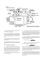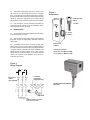
1
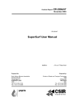
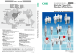
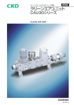
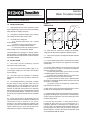
Electric,
Water Circulation Heater
Applies to Heater Model EPW
1.0
INITIAL INSPECTION
Installation/Operation/Maintenance Form MI511
Figure 1
DIMENSIONS
HOLDING BOLTS
FOR BRACKET
29"
1.1 Upon receipt from the carrier, inspect the heater
for possible damage in transit. If necessary, immediately
report damage to shipping company.
1 1/2" OUTLET
11 3/4"
1.2 Verify that the nameplate voltage, phase, wattage
and catalog number comply with the order.
1 1/2" INLET
15"
22 1/2"
1.3
The EPW, when configured:
• as a swimming pool heater, has a catalog
number EPWP;
• as a domestic water or dishwasher water
booster heater, has a catalog number EPWD;
• as a hot water furnace for comfort or process
water heating, has a catalog number EPWH.
These units differ in trim package, i.e. auxiliary controls.
For this reason IT IS IMPORTANT THAT THE UNITS
BE USED ONLY FOR THE SPECIFIC APPLICATIONS
AS STATED ABOVE.
2.0
INSTALLATION
2.1 The heater must be installed by qualified
personnel to code requirements.
2.2 Ensure that the electrical power supply is the
same voltage and phase as the heater with sufficient
current capacity.
2.3 The heater must be installed in a horizontal
position with the outlet at the top and the drain at the
bottom.
2.4 The mounting hardware, as provided, is suitable
for either floor or ceiling mounting. Note that each
mounting bracket is to be attached at the top of the
heating housing by two holding bolts (see Fig.1).
Remove the two bolts and install the first mounting
bracket prior to removing the second two bolts to install
the second mounting bracket. If all bolts are removed
at once the tank may shift which will increase installation
time.
2.5 Please refer to Figure 1 for dimensions. Be sure
to provide adequate space to facilitate installation and
maintenance. Leave a minimum of 24" (60cm)
clearance at the control compartment (opposite side
to the inlet). If the unit is to be mounted under a table or
cabinet a minimum of 30" (75cm) from the floor to the
underside of the cabinet is required for piping.
Knockouts 1",
1 1/4", 1 1/2 & 2"
10 3/4"
7 1/2"
1 1/2" DRAIN
7 1/2"
16 1/4"
4"
15"
2.6 Allow space at sides for the conduit used for power
supply and for thermostat or optional equipment wiring.
2.7 Please refer to Figure 2 for component location and note
the following:
2.7.1 The circulation pump outlet is connected to the heater
inlet located at the end of the unit opposite to the controls
compartment.
2.7.2 A flow switch (optional) is to ensure that the heater will
not be energized if the flow is interrupted. Installations
requiring a flow switch include:
(a) Swimming pool heating systems where the heater
is positioned above the pool water surface.
(b) Whenever the plumbing allows for the heater to be
isolated by shut off valves on the inlet and outlet.
(c) Systems where the heater vessel is allowed to drain
when flow is interrupted. (Without water the built-in limit will
not perform as intended).
(d) Systems where the temperature control bulb is
located away from the outlet.
If a flow switch is not used, and also for pool heating, it is best
to allow the circulating pump to run continuously.
2.7.3 Wire both flow switch and control thermostat to contacts
designated "normally open" and "common". "Normally open"
contacts open on temperature rise on thermostat and close
on flow through switch.
2.7.4 A pressure relief valve is a safety feature which is
intended to open when the system malfunctions or is
improperly operated or maintained. Units equipped with a
pressure relief valve should be fitted with piping to direct the
discharge down and away from personnel or equipment.
NEVER INSTALL A SHUT OFF VALVE ON EITHER SIDE
OF A PRESSURE RELIEF VALVE.
Figure 2
TYPICAL INSTALLATION
Control Fuse
*N.B.
WHERE THERMOSTAT BULB IS LOCATED OTHER
THAN OUTLET, FLOW SWITCH IS RECOMMENDED.
2.7.5 Optional expansion tank (for closed loop systems)
is mounted in the outlet piping.
2.7.6 A 1 1/2" NPT drain plug is fitted at the bottom of
the heater. We recommend use of a drain valve to
simplify clean-out of sludge which may accumulate in
the vessel. Sludge build-up can cause heating element
failure.
2.7.7 For flow rates greater than 50 gpm, to reduce tank
erosion, a bypass loop with regulating valve is
recommended.
2.7.8 Closed loop systems require an air bleed valve,
preferably installed at the highest point in the piping
loop.
3.0
START UP AND OPERATION
3.1 The EPW heater is designed to heat water in a
non-hazardous environment. In some closed loop
systems chemically stabilized ethylene glycol may be
added to the water for freeze protection or to elevate
the boiling point. If you are unsure as to suitability of
glycol to your heating loop contact the factory.
3.2 Check the electrical system for loose connections
and tighten if required.
3.3 After all piping is installed turn the thermostat to its
lowest setting and operate the circulating pump for up to 1/2
hour to check for leaks and to remove air pockets. In closed
loop systems use the air bleed valve to remove entrapped air.
An air lock in the heater vessel could cause the heaters to
run dry and fail prematurely.
3.4 Set the thermostat to the desired temperature. The
temperature rise through the unit will depend on the flow rate
and the heater kilowatt (kw) rating.
For water: GPMUS =
6.83 kw
Temp. Rise (°F)
Example: For a 30 kw heater and a 10°F temperature
rise the flow required in U.S. gallons per minute is:
GPMUS =
(6.83)(30)
10
= 20.4
Adjust the thermostat differential to give the desired cycling
rate. It is best to use the maximum acceptable differential so
as to minimize cycling and prolong component service life.
However, if the system requires close control a narrow
differential setting will be necessary.
3.5 For systems using a by-pass loop, open the by-pass
valve to reduce the load on the pump but not enough to cause
the limit thermostat to open. For pool heating, the ideal bypass opening will result in water leaving the heater at not
more than 90°F.
3.6 The built-in temperature high limit is factory set at
180°F (82°C). This control works best when it is set about
40°F (22°C) above the water outlet temperature. To adjust
the limit control setting remove the small panel on the limit
control to access the adjustment screw. Under normal
operation the heater should not cycle on the limit control.
Figure 4
Accessories
Protective Well
CWI-6
1/2" NPT
3.7 If the limit trips it must be manually reset before the
heater will operate. Prior to reset, the condition(s) which
caused the trip shall be corrected.
4.0
MAINTENANCE
5' (1.5m)
Capillary
4.1 Service to the unit shall only be done when the power
is disconnected at the mains.
4.2 After the first few days of operation, and periodically
thereafter, inspect for piping leaks and loose electrical
connections.
4.3 The EPWD unit, because it is used in an open loop
water heating system, may be subject to sludge build-up if
the water is hard and untreated. This unit must be drained
at regular intervals (depending on water conditions and
operating time) to remove sludge. Once a year a flange
heater must be removed and the vessel inspected and
cleaned as required. Local conditions may cause this
inspection time to vary.
Thermostat
11B06-1
Control Circuit Fuse:
208 & 240V: 2 x MDA 3, 3 AMP,
277 to 600V: 1 x MDA 5, 5 AMP
Figure 3
Wiring Diagram
3φ
1φ
Disconnect
Switch
(not supplied)
To Remote
Thermostat
(supplied loose)
TYPE F61KB FLOW SWITCH
(Optional)
N.B.
REMOVE JUMPER IF OPTIONAL
FLOW SWITCH IS USED.