1
MC
COMBOMAX
Electric boiler with integrated instantaneous water heater
Models from 8 kW to 24 kW :
240 Volts ( single phase )
Use and Care Manual
With installation instructions for the contractor
®
Your COMBOMAX electric boiler has been carefully assembled and factory tested to
provide years of trouble-free service. This manual contains instructions for the safe and
proper installation, operation and maintenance of the boiler, in order to ensure your full
satisfaction
It is imperative that all persons who are expected to install, operate or adjust this boiler read
the instructions carefully.
Any questions regarding the operation, maintenance, service or warranty of this water
heater should be directed to the dealer or distributor you purchased it from. When all
installation steps have been completed, replace this installation manual in its original
envelope, and keep in a safe place near the heater for future reference.
THERMO 2000 INC.
Printed in Canada
revised : January 2006
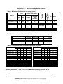
Section 1 : Technical specifications
Nominal load in amps
Model
Kw
BTU/h
Heating
elements
Including
the
circulator
COMBOMAX XX-8
8
27 296
33.3
34.3
COMBOMAX XX-10
10
34 120
41.6
42.6
COMBOMAX XX-15
15
51 180
62.5
63.5
COMBOMAX XX-18
COMBOMAX XX-20
COMBOMAX XX-24
18
20
24
61 416
68 240
81 888
75.0
83.4
100.0
76.0
84.4
101.0
Number of
elements
Power
Stages \
Thermostats \
pilots
Table 1: Boiler specifications 240 Vac (single phase) :
Wire
Cu
Fuse
Amps
2
8
50
2
6
60
4
3
100
4
4
4
3
2
1
100
125
125
1 X 3KW
1 X 5KW
2 X 5KW
2 X 3KW
2 X 4.5KW
4 X 4.5KW
4 X 5KW
4 X 6KW
Table 2 : Boiler and connection dimensions
Model
Capacity
Combomax 23
Combomax 34
Combomax 44
Combomax 64
30 Gal US
40 Gal US
52 Gal US
76 Gal US
Utility
connection
3/4 ’’ Sweat F
3/4 ’’ Sweat F
3/4 ’’ Sweat F
3/4 ’’ Sweat F
Boiler
connection
1’’ NPT F
1’’ NPT F
1’’ NPT F
1’’ NPT F
Height
Diam.
49’’
65’’
55’’
67’’
18’’
18’’
22’’
24’’
Ship.
weight
265 lbs
315 lbs
345 lbs
425 lbs
Table 3 : Domestic hot water production capacity in US gallons
Model
COMBOMAX 23-8
COMBOMAX 23-10
COMBOMAX 23-15
COMBOMAX 23-18
COMBOMAX 23-20
COMBOMAX 23-24
110F
75
87
116
134
145
169
1st hour
140F
44
52
73
85
93
110
180F 110F
28
47
33
59
48
88
57
106
63
117
75
141
110F
97
109
138
156
167
191
1st hour
140F
53
61
82
94
102
119
180F
31
36
51
60
66
78
Model
COMBOMAX 44-8
COMBOMAX 44-10
COMBOMAX 44-15
COMBOMAX 44-18
COMBOMAX 44-20
COMBOMAX 44-24
Continuous
140F 180F
33
24
41
29
62
44
74
53
82
59
99
71
Continuous
110F 140F 180F
47
33
24
59
41
29
88
62
44
106
74
53
117
82
59
141
99
71
Model
COMBOMAX 34-8
COMBOMAX 34-10
COMBOMAX 34-15
COMBOMAX 34-18
COMBOMAX 34-20
COMBOMAX 34-24
Model
COMBOMAX 64-8
COMBOMAX 64-10
COMBOMAX 64-15
COMBOMAX 64-18
COMBOMAX 64-20
COMBOMAX 64-24
1st hour
Continuous
110F 140F 180F 110F 140F 180F
85
48
29
47
33
24
97
56
34
59
41
29
126
77
49
88
62
44
144
89
58
106
74
53
155
97
64
117
82
59
76
179
114
141
99
71
1st hour
110F 140F 180F
121
63
34
133
71
39
162
92
54
180
104
63
191
112
69
215
129
81
With domestic cold water at 40°F and heating water at 180°F
Operating temperature : from 50°F to 190°F; Maximum operating pressure: 30 psi
COMBOMAX
MC
Electric boiler Set-up, use and care guide (revised January 2006), Page 2.
Continuous
110F 140F 180F
47
33
24
59
41
29
88
62
44
106
74
53
117
82
59
141
99
71
THERMO 2000 inc.
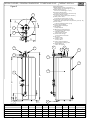
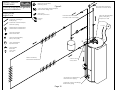
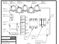
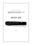
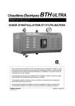
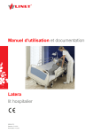
DESSIN D'ATELIER / GENERAL DIMENSIONS COMBOMAX XX-XX
Legeng/Légende:
Figure 2
1) Boiler Water Supply Connection /
Alimentation du chauffage (1" npt F)
2) Boiler Water Return/
Retour du chauffage (1" npt F)
3) Domestic Water inlet /
Entrée eau domestique (3/4" Sweat F)
4) Domestic Water outlet/
Sortie eau domestique (3/4" Sweat F)
5) Safety relief valve/
Soupape de sûreté (3/4" npt M.)
6) Temperature and pressure Gage/
Indicateur de Température et pression (1/2'' npt. M)
7) Drain Valve/
Valve de drainage (3/4'' npt F)
8) Power supply wiring/
Alimentation électrique
9) Pilot Lights/
Lampe témoin
10) Electrical Compartments/
Compartiment électrique
11) Circulator wiring/
Alimentation pompe
12) Thermostat wiring/
Connection thermostat
13) Air vent/
Purgeur d'air
14) Valve 3 voies/
3 ways valve
15) Valve thermostatique/
Thermostatic mixing valve
16) Adjustable leg/
Patte de support
7
H
F
I
1
4
G
14
6
3
15
13
5
8
2
9
12
10
11
A
B
D
C E
DIMENSION/ DIMENSIONAL
Modèle/
A
Model
in.
COMBOMAX 23-XX
49 3/16
COMBOMAX 34-XX
65 1/2
COMBOMAX 44-XX
57 3/4
COMBOMAX 64-XX
65 1/2
Page 3
B
in.
42 1/4
59
49 1/2
58 1/2
C
in.
7 1/4
7 1/4
9 1/2
9 1/2
16
D
in.
4
4
5 3/4
6 1/2
E
in.
1
1
1
1
F
in.
18
18
22
24
G
in.
10 1/2
10 1/2
12 1/2
13 1/2
H
in.
8
8
8
8
I
degrés/degree
75
75
60
60
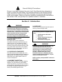
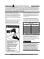
!
General Safety Precautions
Be sure to read and understand the entire Use & Care Manual before attempting to
install or operate this water heater. Pay particular attention to the following General
Safety Precautions. Failure to follow these warnings could cause property damage,
bodily injury or death. Should you have any problems understanding the instructions in
this manual, STOP, and get help from a qualified installer or technician.
Section 2 : Introduction
!
WARNING
The important safeguards and instructions
appearing in this manual are not meant to
cover all possible conditions and situations
that may occur. It should be understood that
common sense, caution and care are factors
which cannot be built into every product.
These factors must be supplied by the
person(s) caring for and operating the unit.
2.1 LOCAL INSTALLATION
REGULATIONS
This water heater must be installed in
accordance with these instructions and must
conform to local, or in the absence of local
codes, with the current edition of the National
Plumbing Code and the National Electric Code.
In any case where instructions in this manual
differ from local or national codes, the local or
national codes take precedence.
2.2 CORROSIVE ATMOSPHERE
The heater should not be located near an air
supply containing halogenated hydrocarbons or
high humidity. The limited warranty is voided
when failure of the water heater is due to a
corrosive atmosphere.
2.4 CHECKLIST
Please check the technical information plate to
ensure you have the right model.
The following items are shipped with the
unit :
• 30 PSI pressure relief valve.
• Drain cock.
• Thermo manometer (heat and
pressure indicator).
• Thermostatic mixing valve
!
WARNING
The boiler should not be located in an area
where leakage from the tank or water
connections will result in damage to the
adjacent area or to lower floors of the
structure. When such areas cannot be
avoided, a suitable drain pan or nonflammable catch pan, adequately drained,
must be installed under the boiler. The pan
must be connected to a drain.
NOTE: Auxiliary catch pan MUST conform to
local codes.
2.3 SHIPMENT INSPECTION
Inspect the water heater for possible shipping
damage. The manufacturer’s responsibility
ceases upon delivery of goods to the carrier in
good condition. Consignee must file any claims
for damage, shortage in shipments, or nondelivery immediately against carrier.
COMBOMAX
MC
Electric boiler Set-up, use and care guide (revised January 2006), Page 4.
Section 3 : INSTALLATION
!
WARNING
3.3 CLEARANCE
The manufacturer’s warranty does not cover
any damage or defect caused by installation
or attachment or use of any special
attachment other than those authorized by
the manufacturer into, onto, or in
conjunction with the water heater. The use of
such unauthorized devices may shorten the
life of the water heater and may endanger life
and property. The manufacturer disclaims
any responsibility for such loss or injury
resulting from the use of such unauthorized
devices.
3.1 SAFETY MEASURES
All domestic and commercial installations will
include a pressure relief valve limiting the
operating pressure to 30 psi.
This COMBOMAXMC electric boiler is designed
for a maximum operating temperature of 190°F.
It is designed as a hot water heating system
only. A 30 to 50% water and ethylene- or
propylene-glycol blend is allowed.
3.2 LOCATION
The COMBOMAXMC water heater should be
installed in a clean, dry location. Long hot water
lines should be insulated to conserve water and
energy. The water heater and water lines should
be protected from exposure to freezing.
COMBOMAXMC water heaters must be installed
vertically. Use the adjustable feet to level the
unit.
The COMBOMAXMC water heater must be
located or protected so as not to be subject to
physical damage, for example, by moving
vehicles, area flooding, etc..
All models can be installed on combustible floors
and in alcoves. If the water heater is to be
installed in a restaurant or other location where
the floor is frequently cleaned, it must be
elevated to provide at least 6 inches of
clearance from the floor to comply with NSF
International recommendations.
The minimum clearances required for proper
inspection and servicing are as follows:
Table 4: Clearances
Left side
Right side
Top
Front
Back
3.4 SYSTEM SETUP
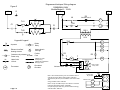
Figures 2, 3 and 4 are general connection
diagrams including the circulator, the expansion
tank, the drain cock, the safety valve, the air
bleeder, the flow check valve and the thermo
manometer. Set-up details follow.
3.5 HEATING WATER CIRCUIT
3.5.1 Connecting the heating water
piping
The boiler may be set up alone or in parallel with
others. Parallel connections should be made
using the reverse-piping method to ensure equal
flow through each boiler.
The boiler water supply connector is located on
top of the boiler and the boiler water return
connector is located to the left of the three-way
valve. They are both threaded NPT female
connectors.
Unions are recommended on the hot and cold
water lines to disconnect the water heater easily
for servicing if necessary.
Dielectric (insulating) unions are required for
protection of the water heater if copper-steel
connections are made.
Use only clean copper or approved plastic pipe
for water connections. Local codes or
regulations shall govern the exact type of
material to be used.
Insulate all pipes containing hot water,
especially in unheated areas.
The room temperature must not exceed 80°F or
27°C.
COMBOMAX
MC
3 inches
3 inches
24 inches
24 inches
3 inches
Electric boiler Set-up, use and care guide (revised January 2006), Page 5.
Install shutoff (ball) valves for servicing
convenience. Install thermometers on the inlet
and outlet lines.
boiler or any part of the circuit. It is preferable to
use a calibrated diaphragm expansion tank.
3.5.5 Makeup valve
Never plug the pressure relief valve to avoid
creating a hazardous situation.
3.5.2 Flow-check valve
If the heating system uses a single circulator, a
flow-check valve must be installed to
minimize gravity flow and heat loss during nondraw periods.
3.5.3 Pressure relief valve
No boiler set-up is complete without a pressure
relief valve. Its pressure rating must not exceed
30 psi (207 kPa). It must conform to the « ASME
Boiler and Pressure Vessel Code» and limit the
boiler operating pressure. It is a safety device,
not a control device.
The BTU per hour rating of the relief valve must
equal or exceed the BTU per hour input of the
boiler(s) or heat source(s) as marked on the
boiler(s) rating plate.
Connecting a makeup valve must be done
according to code. This valve must include a
flow-check valve to maintain the minimum
operating pressure by admitting fresh water from
the cold water supply line in case a leak occurs.
3.5.6 Air bleeder
There should be as little oxygen as possible in
the heating circuit to prevent corrosion. As
foreseen in section 3.5.4, this excludes the use
of air as a pressure regulator within the circuit.
Installing manual or automatic air bleeders
prevents air accumulation within the system.
The bleeders must be set at the highest points
of the system to purge any air accumulated
during system set-up and to check its air
tightness. Bleed the air regularly from the piping,
making sure the heating water causes no bodily
harm or material damage.
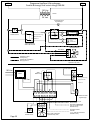
3.5.7 Circulator zoning
Connect the outlet of the relief valve to a
suitable open drain, with the discharge at most
6” above the floor, far from any live electrical
parts. The discharge line must pitch downward
from the valve to allow complete draining and be
no smaller than the outlet of the valve. The end
of the discharge line should not be threaded or
concealed and should be protected from
freezing. No valve of any type, restriction or
reducer coupling should be installed in the
discharge line. Local codes shall govern the
installation of relief valves.
3.5.4 Operating pressure control :
expansion tank
Operating pressure control components ensure
minimum and maximum operating limits are
observed within the design operating
temperature range. These components allow
bleeding air from the piping, prevent boiling and
cavitation at the circulator inlet, while minimizing
the amount of fresh water input. Please contact
a qualified plumber or contractor for more
information on this subject.
A flow-check valve must be installed in each
zone, preferably at the outlet of each circulator,
to prevent water flowing to zones where no heat
is currently required. (see figure 4).
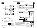
3.5.8 Zone valve zoning
Zone valves with low pressure drop are
recommended. (see figure 3)
3.5.9 Circulator selection criteria
The COMBOMAXMC boiler includes a premounted circulator. The information below will
help you select additional units for multiple
circulator set-ups.
3.5.9.1 Pump flow rate calculation
The boiler output rating must correspond to the
calculated heating load. Use the equation below
to calculate the pump flow rate:
The expansion tank connection point must be
carefully chosen to prevent a situation where
closing a valve would isolate the tank from the
COMBOMAX
MC
Electric boiler Set-up, use and care guide (revised January 2006), Page 6.
Pump flow rate = Boiler output ÷ BWTD ÷ 500
•
•
•
Pump flow rate is expressed in U.S. gallons
per minute or GPM.
The Boiler output ( in net BTU per hour) is
the maximum amount of heat to be
transferred through the heating circuit to
meet the hot water demand.
BWTD is the boiler water temperature drop
through the heating circuit.
For example, a 24 Kw COMBOMAXMC boiler has
a rated output of 81,964 BTU/hour. The system
is designed for a boiler water temperature drop
(BWTD) of 20°F.
reverse-piping method to ensure equal flow
through each boiler.
The HOT WATER OUTLET and the COLD
WATER INLET connections are clearly marked.
Inlet water connections (COLD WATER INLET)
are to be made to the copper pipe (sweat
connection) at the bottom of the heater. Outlet
water connections (HOT WATER OUTLET) are
to be made to the three-way thermostatically
controlled valve (sweat connection) at the top of
the heater.
The installation of copper unions or copper alloy
unions is recommended on the HOT and COLD
water lines, so that the water heater may be
easily disconnected for servicing if necessary.
These unions must be dielectric (insulating) if
you are making steel-copper connections.
Pump flow rate = 81,964 ÷ 20 ÷ 500 = 8,2 GPM.
The following table shows the required flow rate
as a function of boiler water temperature drop
(BWTD) and rated power output.
Table 5 : BWTD vs. flow (GPM)
Model
Kw
COMBOMAX XX-8
COMBOMAX XX-10
COMBOMAX XX-15
COMBOMAX XX-18
COMBOMAX XX-20
COMBOMAX XX-24
8
10
15
18
20
24
10o
F
5,5
6,8
10,2
12,3
13,7
16,4
BWTD
20o 30o
F
F
2,7 1,8
3,4 2,3
5,1 3,4
6,1 4,1
6,8 4,6
8,2 5,5
40o
F
1,4
1,7
2,6
3,1
3,4
4,1
3.5.9.2 Selecting a circulator
Consult the manufacturer’s operating
characteristic curves to select the proper model.
These curves plot flow versus pressure, together
with other information such as efficiency and
power. Ask your pump dealer or HVAC
wholesaler to recommend the circulator which
best fits your needs.
3.6 DOMESTIC HOT WATER CIRCUIT
3.6.1 Connecting the domestic hot water
piping
The COMBOMAXMC domestic hot water coil may
be set up alone or in parallel combination with
other COMBOMAXMC units or storage tanks.
Parallel connections should be made using the
COMBOMAX
MC
A shutoff (ball) valve is present on the
COMBOMAXMC domestic hot water outlet for
servicing convenience.
Use only clean copper or approved plastic pipe
for water connections. Local codes or
regulations shall govern the exact type of
material to be used.
Insulate all pipes containing hot water,
especially in unheated areas.
Thermometer(s) should be installed to indicate
the temperature of the water at or near the outlet
of the water heater and storage tank(s), if
provided.
3.6.2 Expansion tank on the cold water
supply line
Determine if a flow check valve, a back flow
preventer, a pressure-reducing valve, a water
meter or a water softener is present on the cold
water supply line.
A flow check valve creates a closed system and
prevents the water, as it is being heated, from
expanding back into the cold water supply line.
Pressure can build up within the water heater,
causing the pressure relief valve to operate
during a heating cycle. This excessive operation
can cause premature failure of the relief valve
and possibly of the water heater itself.
Replacing the relief valve will not correct the
problem. One method of preventing pressure
build-up is to install an expansion tank on the
Electric boiler Set-up, use and care guide (revised January 2006), Page 7.
cold water supply line between the
COMBOMAXMC unit and flow check valve.
Contact your installing contractor, water
supplier, local plumbing inspector or plumbing
supply house for assistance.
3.6.3 Recirculation line (if applicable)
If a recirculation line is installed, the return
connection should be made to a tee close to the
inlet connection on the water heater. A check
valve should always be installed in the
recirculation line to prevent cold water from
entering.
3.6.4 Domestic hot water temperature
and pressure relief valve
An automatic temperature and pressure relief
valve must be installed at set-up time. No valve
of any type should be placed between the safety
relief valve and the water heater. Use a tee to
set the relief valve onto the hot water outlet. The
pressure rating of the relief valve must not
exceed 150 psi.
The BTU per hour rating of the relief valve must
equal or exceed the BTU per hour input of the
boiler(s) or heat source(s) as recorded on the
boiler(s) rating plate. For a circulating tank
installation, the separate storage tank(s) must
have similar protection.
Connect the outlet of the relief valve to a
suitable open drain, with the discharge at most
6” above the floor, far from any live electrical
parts. The discharge line must pitch downward
from the valve to allow complete draining and be
no smaller than the outlet of the valve. The end
of the discharge line should not be threaded or
concealed and should be protected from
freezing. No valve of any type, restriction or
reducer coupling should be installed in the
discharge line. Local codes shall govern the
installation of relief valves.
3.6.5 Thermostatically controlled mixing
valve (included)
For general-purpose hot water requirements in a
domestic environment, a thermostatically
controlled mixing valve is recommended to
reduce the risk of scald injury. Contact a
licensed plumber or the local plumbing authority
for further information. Adjust the mixing valve to
the lowest required temperature setting.
COMBOMAX
MC
3.7 BOILER WIRING
The boiler cabling and grounding must conform
to local codes or, in their absence, to the
National Electrical Code.
Power must be provided by a 120/240 volt
(single phase, 60 Hz) circuit, appropriately fused
and with 3-wire plus ground cabling of sufficient
gage. The fuse and cabling gauge may be
determined from the boiler rating plate.
3.8 CIRCULATOR WIRING
The COMBOMAXMC heating pump (120 Vac,
1/25 Hp) is connected to the C&C terminals on
the boiler electrical panel. The control circuit is
designed to start the pump upon receiving a
heating signal from the thermostat or priority
aquastat.
3.9 CONNECTING THE THERMOSTAT
3.9.1 240V models
3.9.1.1 Single heating zone
Connect the low-voltage thermostat to the T&T
terminals on the COMBOMAXMC electrical panel
(DO NOT apply current to these terminals).
(see figure 10).
3.9.1.2 Zone valve zoning
Connect the low-voltage thermostat to the zone
valve. The components must wired such that,
upon a heating signal from a thermostat, only
the corresponding zone valve will be actuated
and will in turn activate the COMBOMAXMC
circulator relay. Connect the zone valve switch
to the T&T terminals on the COMBOMAXMC
electrical panel (DO NOT apply current to
these terminals). See figures 9 and 10.
The transformer used to power the zone valves
must be of sufficient capacity to handle the load
represented by all zone valves.
3.9.1.3 Multiple circulator zoning
Connect the low-voltage thermostat to the relay
(Honeywell #RA-889, RA-89A). The components
must wired such that, upon a heating signal from
a thermostat, only the corresponding circulator
will be activated. See figure 9.
3.10 PRIORITIZING TERMINAL POST
The K&K terminals on the electrical panel create
a dry contact when the domestic hot water
priority aquastat contact closes.
Electric boiler Set-up, use and care guide (revised January 2006), Page 8.
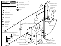
3.11 BI-ENERGY SETUP
To take advantage of a special domestic electric
utility rate, your COMBOMAXMC boiler can be
combined with an existing oil or gas-fired
furnace. Please contact your utility to make sure
your building is eligible and to find out about the
new wiring configuration. Please refer to figures
7 and 8 for the set-up required.
The CBE-EM bi-energy switching control
(available as an option) is especially designed to
satisfy utility requirements. The CBE-EM control
selects the cheapest energy source according to
the outdoor temperature, the indoor temperature
setting and any signal provided by the utility.
The CBE-EM bi-energy control starts up the oil
burner upon receiving the appropriate signal,
even if the thermostat is sending no heating
signal. The oil burner stops when the boiler
reaches its high-limit point. For this reason, the
plumbing system must be equipped with a flow
check valve or zone valves.
The 3-way zone valve (1’’ NPT F) which comes
with the CBE-EM control, directs the heating
water to the oil burner or the COMBOMAXMC
unit depending on the signal sent to it by the
external bi-energy sensor. Thus, your oil burner
can cool down while eliminating energy losses
up the chimney or by conduction in the furnace
room .
COMBOMAX
MC
Electric boiler Set-up, use and care guide (revised January 2006), Page 9.
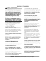
Section 4 : Operation
! SAFETY PRECAUTIONS
Before operating this water heater, be sure to
read and follow these instructions, as well as
the warnings printed in this manual. Failure
to do so can result in unsafe operation of the
water heater resulting in property damage,
bodily injury, or death. Should you have any
problems reading, following or difficulty in
understanding the instructions in this
manual, STOP, and get help from a qualified
person.
Do not turn on the water heater unless it is
filled with water. Do not turn on water heater
if cold water supply shut-off valve is closed.
Once the plumbing and electrical connections
are completed, your COMBOMAXMC unit is
ready for automatic operation.
4.1 FILLING THE TANK
Open the outlet valve (in a zone valve system,
manually open the zone valves).
Open the boiler inlet valve. Bleed the air from
the boiler tank by opening the safety valve atop
the boiler while you are filling the tank.
Leave all valves open. Reset the zone valves to
automatic operation. Check for leaks and repair
if necessary.
Bleed the air from all zones if required. Check
the boiler pressure gauge. A pressure reading
between 15 and 20 psi is normal for most
installations.
4.2 FILLING THE HEATING COIL
Make sure all drain cocks are closed.
Open the nearest domestic hot water tap as well
as any control valve on the water heater outlet
(the copper tube atop the boiler).
Open the cold water inlet valve on the heater
inlet tube. (the copper tube on the left side of the
unit).
Close the domestic hot water tap as soon as
water flows out of it. Fix any leaks
4.3 ADJUSTING THE AQUASTATS
Once all air has been bled from the system and
all components (valves, bleeders, controls) have
been properly adjusted, the boiler can be put
into operation. Never operate the boiler before
these adjustments are complete.
Bear in mind safety and energy-saving
considerations when adjusting the boiler water
temperature with the aquastats. It is most
energy-efficient to set them as low as possible,
in a manner consistent with your heating needs.
However, a minimum temperature of 160°F is
recommended for domestic hot water
production.
Each aquastat controls a boiler stage (in the
240V model, each element has its own
aquastat). Adjust the setting of each aquastat by
turning the dial scaled in degrees Celsius and
Fahrenheit. See figure 10 for aquastat
identification.
Set the first aquastat to the highest outlet
temperature required by the heating system.
Thermo 2000 inc. recommends a setting of
180°F.
Adjust the second aquastat 1°F to 20°F below
the first aquastat setting. Usually, a setting 5°F
below that of the first aquastat, or 175°F,
provides good results in a system designed for a
20°F temperature drop between the tank inlet
and outlet.
Proceed in a similar manner for the 3rd and 4th
aquastats, which will result in settings of 170°F
and 165°F. Thus, the number of elements in
operation will increase (or decrease) according
to the settings and the drop (or rise) in the
heating water temperature.
The domestic hot water priority aquastat should
be adjusted to a setting 5oF below that of the last
stage or 4th aquastat, i.e., 160°F.
At system start-up (on the first heating day of the
season), ìt may take quite some time for the
boiler water to reach its operating temperature.
Check the thermo manometer.
Open all other hot water taps fed by this heating
coil to bleed the air trapped behind them.
COMBOMAX
MC
Electric boiler Set-up, use and care guide (revised January 2006), Page 10.
Adjust the boiler aquastats as required. Please
note that lowering the setting will not have an
immediate effect as the heat stored in the boiler
water must first be consumed. Check the boiler
water temperature periodically. Further
adjustments may be required as the system
goes through several space and water heating
cycles.
Note: The maximum setting for the boiler outlet
temperature is 190°F.
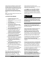
4.4 STARTUP PROCEDURE
1. Fill tank and coil as described in
sections 4.1 and 4.2.
2. Adjust temperature levels as described
in section 4.3
3. Set domestic thermostat level(s) below
room temperature.
4. Activate boiler breakers.
5. The main boiler contact should close
and all elements should turn on, along
with their pilot lights.
6. The circulator should start up and the 3way valve should switch to the A side.
7. Boiler temperature should rise.
8. Circulator stops and the 3-way valve
switches to the B side when boiler
temperature exceeds the setting of the
domestic hot water priority aquastat.
9. Boiler temperature rises and the
elements and corresponding pilot lights
turn off one after the other as their
temperature setting is reached.
10. When all elements are off, increase the
setting of the domestic thermostat(s) to
a point above room temperature.
11. Circulator should start up following a
delay period.
12. Heating elements should turn back on
as their temperature setting is reached;
this could take a few minutes.
13. Circulator runs as long as a demand
exists for heating. When circulator turns
off …
14. Boiler temperature rises. Heating
elements and corresponding pilot lights
should turn off as their temperature
setting is reached.
Thus, boiler power requirements depend on
heating demand within the building. If only one
heating element is required to satisfy the
demand, only one is activated ; if two are
required, two are activated, etc ... You thus
COMBOMAX
MC
avoid excessive wear and tear on the
components due to numerous on-off cycles and
reduce your total heating costs.
4.5 DOMESTIC HOT WATER STARTUP
Maximum boiler water temperature is 190°F.
This should be 20°F to 40°F above the desired
temperature for domestic hot water. In practice,
the boiler water temperature should be between
160°F and 180°F.
!
DANGER
An excessively high setting can cause
scalding. Use the thermostatically controlled
mixing valve included with the unit to lower
the domestic hot water temperature and thus
the risk of injury.
When the boiler water temperature falls below
the setting of the domestic hot water priority
aquastat, the 3-way valve switches to side A and
the circulator starts up.
When the boiler water temperature reaches the
setting of the domestic hot water priority
aquastat, the 3-way valve returns to side B
unless other zones are calling for heat. The
heating elements remain on until they reach
their set points. It is normal to observe the boiler
cycling on and off close to the highest set point,
particularly if a single zone is calling for heat.
Considerable time may elapse from a cold start
to the moment when the highest set point is
reached. Check the domestic hot water
temperature as soon as the first heating cycle is
complete.
Lowering the set points has no immediate effect.
The boiler water heat must first be transferred to
the coil. Additional checks will be necessary at
the end of successive heating cycles. Further
adjustments may be required as time goes by.
The domestic hot water priority aquastat is set at
its minimum at shipping time. It can be
increased to 190°F for commercial use.
Remember that domestic hot water hotter than
125°F can cause scalds. Use this minimum
setting as a starting point for any further
adjustments. Normally, the domestic hot
water priority aquastat is set to 5°F below the
lowest heating element aquastat set point.
Electric boiler Set-up, use and care guide (revised January 2006), Page 11.
4.6 ADJUSTING THE MIXING VALVE
A thermostatically controlled mixing valve works
automatically thanks to the thermostatic element
controlling the mix of very hot and cold water as
required to provide safe domestic hot water
under variable conditions.
To adjust the mixing valve setting, carefully open
a hot water tap. Protect yourself against the
possibility of scalding. Measure the hot water
temperature and adjust it with the mixing valve,
following the manufacturer’s instructions. Lock
the adjusting valve in place at the proper setting.
A higher boiler water temperature setting is now
possible thanks to this moderating effect. The
boiler water in the COMBOMAXMC tank acts as a
buffer and increases the boiler efficiency as well
as the amount of domestic hot water produced.
To increase the ad hoc or general hot water
production capacity, first adjust the domestic hot
water priority aquastat setting (e.g., from 140°F
to 180°F), then the mixing valve setting (e.g.,
from 90°F to 120°F).
Some sanitary uses may require different setting
ranges or dedicated piping.
COMBOMAX
MC
Electric boiler Set-up, use and care guide (revised January 2006), Page 12.
Section 5 : Maintenance
Regular boiler maintenance will ensure troublefree service for many years. It is recommended
that you set up and follow a maintenance
program. All components fail eventually. The use
of incorrect replacement parts or disregarding
safety procedures and warnings during repairs
may reduce the boiler safety level and shorten its
useful life.
The owner should set up the following
maintenance program.
5.1 BOILER WATER PIPING :
Annual visual inspection.
Check for leaks close to connections, unions and
valves. Repair as needed.
5.2 BOILER CIRCUIT SAFETY VALVE:
Monthly inspection.
To be checked manually to ensure safety and
proper operation. Air trapped in the boiler is bled.
Make sure the water is discharged to a floor drain
and that no bystander is splashed. Use the lever
to open the safety valve. Hot water should come
flowing out. Upon releasing the lever, the safety
valve should shut tight. If it does not, it must be
replaced by an identical or equivalent model.
Never plug a safety valve.
5.3 DOMESTIC PIPING :
Annual visual inspection.
Check for leaks close to connections, unions and
valves. Repair as needed.
5.4 DOMESTIC CIRCUIT SAFETY VALVE
(TEMPERATURE & PRESSURE):
Annual inspection.
To be checked manually to ensure safety and
proper operation. Air trapped in the boiler is bled.
flowing out. Upon releasing the lever, the safety
valve should shut tight. If it does not, it must be
replaced by an identical or equivalent model.
Never plug a safety valve.
5.5 SCALE BUILD-UP :
Monthly inspection.
This problem occurs infrequently under very
specific conditions. The main symptom is a drop
in domestic water pressure. A water softener will
solve the problem.
A proper chemical cleaning is a more efficient
solution. A scale dissolving product may be used,
paying careful attention to the manufacturer’s
recommendations. Do not use muriatic or
hydrochloric acid-based products. Carefully flush
the products after use. Contact your plumber to
remove scale build-up from the coil.
!
WARNING
The manufacturer’s warranty DOES NOT
cover problems caused by improper
installation or maintenance. If the safety valve
opens periodically, it may be due to the
expansion tank. Immediately call a qualified
technician to appraise and repair the problem.
NOTE: To prevent tank breakage, trapped air
must periodically be bled from it by opening
the safety valve.
!
DANGER
Before manually opening the safety valve,
make sure no bystander will accidentally be
splashed by the hot water. The discharged
water should be directed to a floor drain to
prevent scalding and damage.
Make sure the water is discharged to a floor drain
and that no bystander is splashed. Use the lever
to open the safety valve. Hot water should come
THERMO 2OOO INC.
500, 9
Avenue, C.P. 639, RICHMOND (QUÉBEC) JOB 2HO
TÉL.: (819) 826-5613 FAX: (819) 826-6370
ième
!
General Safety Precautions
Be sure to read and understand the entire Use & Care Manual before attempting to install
or operate this COMBOMAXMC unit. Pay particular attention to the following General Safety
Precautions. Failure to follow these warnings could cause property damage, bodily injury or
death. Should you have any problems understanding the instructions in this manual, STOP,
and get help from a qualified installer or technician.
To meet commercial hot water needs, the
aquastat on this water heater is adjustable up to
190°F. However, water temperatures over 125°F
can cause severe burns instantly or death from
scalds. 125°F is the preferred starting point for
setting the control to supply general-purpose hot
water.
Safety and energy conservation are factors to be
considered when setting the water temperature
on the aquastat. The most energy efficient
operation will result when the temperature
setting is the lowest that satisfies requirements.
Maximum water temperature occurs just after
burner or the energy source has shut off. To find
hot water temperature being delivered, turn on a
hot water faucet and place a thermometer in the
hot water stream.
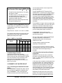
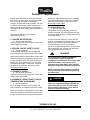
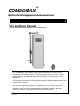
The following chart details the relationship of
water temperature and time with regard to scald
injury and may be used as a guide in determining
the safest water temperature for your applications.
TIME TO SCALDING VS TEMPERATURE
RELATIONSHIP
Temperature
Time to scalding
120°F
Over 5 minutes
125°F
1-1/2 to 2 minutes
130°F
About 30 seconds
135°F
About 10 seconds
140°F
Less than 5 seconds
145°F
Less than 3 seconds
150°F
About 1-1/2 second
155°F
About 1 second
With kind permission from the Shriners Burn Institute
The temperature of the water in the heater can be
set by turning the temperature dial on the
aquastat. To comply with safety regulations the
aquastat was set at its lowest setting before water
heater was shipped from the factory.
!
DANGER
There is a hot water scald potential if the
aquastat is set too high. When this water
heater is supplying general purpose hot water
requirements for use by individuals, a
thermostatically controlled mixing valve for
reducing point-of-use water temperature is
recommended to reduce the risk of scald
injury. Contact a licensed plumber or local
plumbing authority for further information.
COMBOMAX
MC
Electric boiler Set-up, use and care guide (revised January 2006), Page 14.
THERMO 2000 inc.
COMBOMAX
Réducteur de pression/
Reducing valve
Schéma d'installation général/
General installation
Valve de mélange thermostatique/
Thermostatic mixing valve
Simple Zone/
Single Zone
Anti retour/
Back flow preventer
Tuyauterie chauffage/
Boiler piping
Figure 2
Eau chaude domestique/
Domestic hot water mixed
Valve de sécurité (T&P)/
Safety valve (T&P)
Eau froide domestique/
Domestic cold water supply
Pompe/
Pump
à ajouter/ to add
Thermostat
Tuyauterie eau domestique/
Domestic piping
L1 L2 N
Manomètre & thermomètre/
Manometer & thermometer
Valve anti-gravité/
Flow check valve
Valve de sécurité (T&P)
Safety valve (T&P)
B
Vase d'expansion/
Expansion tank
Valve à bille/
Ball valve
Vent d'air/
Air vent
AB
Plinthes à ailettes/
Finnes-Tube baseboard
Valve 3 voies/
3 way-valve
Tuyauterie eau domestique/
Domestic water piping
Tuyauterie eau de chauffage/
Boiler water piping
Page 15
A
TT
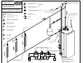
THERMO 2000 inc.
COMBOMAX
Schéma d'installation général/
General installation
Système multizones (valves)/
Multi-zone system using valves
Tuyauterie chauffage/
Boiler piping
Tuyauterie eau domestique/
Domestic piping
Réducteur de pression/
Reducing valve
Eau chaude domestique/
Domestic hot water mixed
Figure 3
Valve de zonage électrique/
Electric zone valve
Valve de mélange thermostatique/
Thermostatic mixing valve
Eau froide domestique/
Domestic cold water supply
Valve de sécurité (T&P)/
Safety valve (T&P)
Anti retour/
Back flow preventer
à ajouter/ to add
Pompe/
Pump
L1 L2 N
Manomètre & thermomètre/
Manometer & thermometer
Valve anti-gravité/
Flow check valve
Valve de sécurité (T&P)
Safety valve (T&P)
Thermostat
B
Vase d'expansion/
Expansion tank
Valve à bille/
Ball valve
A
TT
AB
Vent d'air/
Air vent
Valve 3 voies/
3 way-valve
Diagramme électrique/ Wiring diagram
Raccordement de zone valves/ Wiring for zoned valves system
Thermostat
Zone 1
Thermostat
Zone 2
Thermostat
Zone 3
Note 1
Block terminal thermostat/Thermostat terminal block
COMBOMAX: sur panneau électrique COMBOMAX/
on COMBOMAX electric pannel
2
Zone
valves
24 Vac
2
2
Zone
valves
4
1
3
2
2
Zone
valves
4
1
3
2
4
1
3
Transfo
Note 1
T
Plinthes à ailettes/
Finnes-Tube baseboard
40Va Transfo (3 zones)
20Va Transfo (2 zones)
120 Vac
Electrical service
Page 16
T
Tuyauterie eau domestique/
Domestic water piping
Tuyauterie eau de chauffage/
Boiler water piping
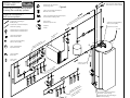
THERMO 2000 inc.
COMBOMAX
Système primaire/secondaire
Primary/Secondary system
Système multizones /
Multi-zone system
Tuyauterie chauffage/
Boiler piping
Tuyauterie eau domestique/
Domestic piping
Réducteur de pression/
Reducing valve
Valve de mélange thermostatique/
Thermostatic mixing valve
Anti retour/
Back flow preventer
Pompe/
Pump
teu
dia
Ra oils
C
Valve anti-gravité/
Flow check valve
Vase d'expansion/
Expansion tank
Figure 4
Valve de zonage électrique/
Electric zone valve
Manomètre & thermomètre/
Manometer & thermometer
Valve de sécurité (T&P)
Safety valve (T&P)
Eau chaude domestique/
Domestic hot water mixed
ly
/
ue pp
tiq r su
s
me ate
do ld w
e
o
d c
roi
u f stic
Ea o m e
D
Valve de sécurité (T&P)/
Safety valve (T&P)
à ajouter/ to add
L1 L2 N
rs/
rd
/
es oa
ett seb
l
i
a a
sà eb
he -Tub
t
n
Pli nes
Fin
B
Valve à bille/
Ball valve
A
TT
AB
Vent d'air/
Air vent
Valve 3 voies/
3 way-valve
e/
eig
n
g
de ltin
nte me
Fo ow
Sn
Page 17
t/
an e
uff zon
a
ch ing
er at
n/
ch nt he
tio
n
c
a
l
e
a
P di
inj ion
Ra
e àject
p
m in
Po mp
Pu
Tuyauterie eau domestique/
Domestic water piping
Tuyauterie eau de chauffage/
Boiler water piping
Diagramme électrique/ Wiri ng diagram
COMBOMAX 240V
Modèle/Model 6 - 10 KW
L2
Figure 5
L1
G
N
F
R5
Voir/see note 2
HL
C1
EL1
TH1
R4
C1
C
C1
EL2
TH2
C
120 V
24 V
Légende/ Legend
TH
C
HL
Aquastat
TH5
R
Élément chauffant/
Heating element
Lampe témoin
Pilot light
Contacteur de puissance
Power relay
Fusible
Fuse
Haute limite
Hi-Limit
Thermostat
R1
Relais
Relay
R2
R3
R3
T
Cablage en usine/
Factory wiring
T
R4
Chauffage/ Heating
Brun/ Brown
Cablage par l'installateur/
Wiring by others
Circulateur/
Circulator
R3
B
Noir / Black
Voir/see note 2 R6
Bleu /
R1 Blue
AB
Valve 3 voies /
3-way valve
A
Recirculation
R2
Note 1: Bloc terminal (24VAC) pour une installation avec le
controleur bi-énergie Thermo 2000 modèle: "CBE-EM"/
Terminal block (24 VAC) for an installation with Thermo 2000
dual
energy controller model: "CBE-EM"
Page 18
Note 2: Couper le cavalier lorsque vous utilisez le controleur
bi-énergie Thermo2000 modèle: "CBE-EM"/
Cut open this jumper when using Thermo 2000 dual energy
controller model: "CBE-EM"
Contact sec/
Dry contact
Voir/see note 1
R5
K
K
E2
R6
V2
Diagramme électrique/ Wiri ng diagram
COMBOMAX 240V : modèle/ model 15 - 24 KW
Figure 6
L1
G
L2
N
F
R5
Voir/see note 2
HL
C1
EL1
TH1
R4
C
C1
C1
TH2
EL2
120 V
TH3
EL3
24 V
C1
C
TH5
C1
R1
EL4
TH4
R2
R3
R3
T
Légende/ Legend
TH
C
HL
Aquastat
R
Contacteur de puissance
Power relay
Fusible
Fuse
Page 19
Brun/ Brown
Relais
Relay
Lampe témoin
Pilot light
Thermostat
T
R4
Chauffage/ Heating
Élément chauffant/
Heating element
Haute limite
Hi-Limit
R3
Voir/see note 2 R6
Bleu /
R1 Blue
Note 1: Bloc terminal (24VAC) pour une installation avec le
controleur bi-énergie Thermo 2000 modèle: "CBE-EM"/
Terminal block (24 VAC) for an installation with Thermo 2000
Cablage par l'installateur/ dual
energy controller model: "CBE-EM"
Wiring by others
Note 2: Couper le cavalier lorsque vous utilisez le controleur
bi-énergie Thermo2000 modèle: "CBE-EM"/
Circulateur/
Cut open this jumper when using Thermo 2000 dual energy
Circulator
controller model: "CBE-EM"
Cablage en usine/
Factory wiring
B
Noir / Black
AB
Valve 3 voies /
3-way valve
A
Recirculation
R2
Contact sec/
Dry contact
Voir/see note 1
R5
K
K
E2
R6
V2
Figure 7
Diagramme électrique/ Wiri ng diagram
Contrôle Bi-énergy/ Dual control ener gy CBE-EM
L1
N
120 Vac
Transfo
24 Vac
Lumière haut tarif/
High tarif light
H
H
V2
V3
Sonde extérieur/
Outdoor sensor
E2
E2
Bi-energie/ Dual energy
Relais/ Relay
COMBOMAX
V2
E1
Electrique/ Ele ctric
SPDT
Relais/ Relay
Mazout/ Oil
T2
T
T1
T
Relais chaudière
mazout/
Oil boiler Relay
Interrupteur DPDT
Switch ON-OFF-ON
Electrique/ Electric
Noir/ Black
V1
B
Brun/ Brown
AB
Bleu/ Blue
A
Cablage en usine/
Factory wiring
Mazout/ Oil
Cablage par l'installateur/
Wiring by others
Valve 3 voies optionnelle/
Optional 3-way valve
Interrupteur DPDT
Switch ON-OFF-ON
120 Vac
SPDT
Relais/ Relay
Transfo
Bi-energie/ Dual energy
24 Vac
Electrique/ Ele ctric
Mazout/ Oil
H H V1 V2 V3 T1 T2 E1 E2
Sonde extérieur/
Outdoor sensor
Page 20
Chaudière électrique/
Electric boiler
BTH/ GTH/ COMBOMAX
("E2 V2" bornier 24 Vac/
terminal E2-V2)
Noir/ Black
Bleu/ Blue
Brun/ Brown
Lumière haut tarif/
High tarif light
Valve 3 voies optionnelle/
Optional 3-way valve
Chaudière mazout
Oil boiler
("T T" relais de combustion/
oil boiler burner)
Figure 8
THERMO 2000 inc.
COMBOMAX
Réducteur de pression/
Reducing valve
Schéma d'installation général/
General installation
Valve de mélange thermostatique/
Thermostatic mixing valve
Bi-énergie avec Valve 3 Voies/
Dual Energy with 3-way valve
Anti retour/
Back flow preventer
Eau froide domestique/
Domestic cold water supply
Eau chaude domestique/
Domestic hot water mixed
Valve de sécurité (T&P)/
Safety valve (T&P)
à ajouter/ to add
Thermostat
Pompe/
Pump
Tuyauterie chauffage/
Boiler piping
L1 L2 N
Tuyauterie eau domestique/
Domestic piping
Manomètre & thermomètre/
Manometer & thermometer
Valve anti-gravité/
Flow check valve
A
Valve de sécurité (T&P)
Safety valve (T&P)
TT
E2 V2
B
AB
Installation Bi-énergie/
Dual energy installation
Vase d'expansion/
Expansion tank
Installation d'une voie de contournement
avec valve électrique (à ajouter)/
Install by-pass with zone valve (to add)
Valve à bille/
Ball valve
KK
Voir/See Note 1
Vent d'air/
Air vent
B
Diagramme électrique/ Wiring diagram
Raccordement de zone valves pour voie de contournement Bi-énergie/
Wiring for zoned valves system for dual energy by-pass
K
AB
K
Block terminal K-K
/K-K terminal block
2
Zone
valves
Zone
valves
24
Vac
A
sur panneau électrique COMBOMAX/
on COMBOMAX electric pannel
2
4
1
Transfo
3
Valve 3 voies NO 2/
3 way-valve NO 2
40Va Transfo (3 zones)
20Va Transfo (2 zones)
120 Vac
Electrical service
Page 21
Sonde extérieure Bi-énergie/
Dual Energy outside sensor
Contrôle Bi-énergie CBE-EM/
Dual energy control CBE-EM
TT
Tuyauterie eau domestique/
Domestic water piping
Tuyauterie eau de chauffage/
Boiler water piping
Note 1: Ajuster la température d'eau de chauffage
du COMBOMAX de 10 à 15 degré F. en dessous
de la température d'opération de la chaudière au mazout.
Figure 9
Diagramme électrique/ Wiri ng diagram
Raccordement de zone valves/ Wiring for zoned va lves system
Thermostat
Zone 1
Thermostat
Zone 2
Thermostat
Zone 3
Note 1
Block terminal thermostat
/Thermostat terminal block
sur panneau électrique COMBOMAX/
on COMBOMAX electric pannel
2
Zone
valves
24 Vac
2
2
Zone
valves
4
1
2
2
Zone
valves
4
1
3
2
4
1
3
3
Transfo
Note 1
T
T
40Va Transfo (3 zones)
20Va Transfo (2 zones)
Diagramme électrique/ Wiri ng diagram
Raccordement de multiples circulateurs/ Wiring for m ultiple circulators
120 Vac
Electrical service
Thermostat
Zone 1
Thermostat
Zone 2
T
T
T
Relais/Relay
RA845A
2
1
4
6
3
5
T
Relais/Relay
RA845A
2
1
Circulateur/
circulator
Zone 1
4
6
3
5
Circulateur/
circulator
Zone 2
L1 L2
120Vac
electrical service
Diagramme électrique/ Wiri ng diagram
Raccordement de zone valves pour voie de contournement Bi-énergie/
Wiring for zoned valves system for dual e nergy by-pass
K
K
Block terminal K-K
/K-K terminal block
2
Zone
valves
Zone
valves
24
Vac
4
1
Transfo
40Va Transfo (3 zones)
20Va Transfo (2 zones)
120 Vac
Electrical service
Page 22
sur panneau électrique COMBOMAX/
on COMBOMAX electric pannel
2
3
Aquastat
Priorité DHW/
DHW priority
(Sugg: 160F)
Aquastat
Élément no. 4/
Element no. 4
(Sugg: 165F)
Aquastat
Élément no. 3/
Element no. 3
(Sugg: 170F)
Figure 10
Aquastat
Élément no. 2/
Element no. 2
(Sugg: 175F)
Aquastat
Élément no. 1/
Element no. 1
(Sugg: 180F)
Bornier
valve 3 voies/
3 way valve
terminal block
Bornier/
Terminal block
C-C
(Pompe/ Pump)
Transformateur
contrôle/
Transformer
Control
Fusible
contrôle/
Control
Fuse
THERMO 2000 inc.
Panneau de contrôlel/
Control pannel
COMBOMAX 240V
Mise à
la terre/
Relais
Valve
3 voies
3 way
Valve
Relay
Relais
Contact
sec K - K
Dry Contact
K-K
Relay
Relais
Priorité
DHW
DHW
Priority
Relay
Relais
Pompe
Pump
Relay
Relais BE
Éléments
Element
Dual Energy
Relay
Relais BE
Valve
3 Voies
Grund
3 way valve
Dual Energy
Relay
Contacteur
principal/
Main
Contactor
Page 23
Bornier de
raccordement/
Main terminal
Block
Bornier/ Terminal block
K-K (contact sec/ Dry contact)
E2-V2 (Bi-énergie/ Dual Energy)
T-T (Thermostat)
COMBOMAX
TM
LIMITED WARRANTY
Warranty Coverage for Residential Installation.
Thermo 2000 Inc. hereby warrants to the original residential purchaser that the
COMBOMAX tank and exchanger (coil assembly) installed in a residential setting
shall be free of leaks during normal use and service for a period of fifteen (15) years
from the date of purchase as long as the original residential purchaser owns the
home in which the unit was originally installed, the ten (10) years in full and years
eleven (11) through fifteen (15) prorated 20% each year at suggested retail price.
Residential setting shall mean usage in a single-family dwelling in which the
consumer resides on a permanent basis. Also, residential setting shall mean use in
multiple family dwellings in which one (1) COMBOMAX tank and exchanger is to be
use in only one (1) dwelling. In the event that a leak should develop and occur
within this limited warranty period due to defective material or workmanship, such
leak having been verified by an authorized company representative, Thermo 2000
inc. will repair or replace at our sole option the failed unit with the nearest
comparable model at the time of replacement.
The original residential purchaser is responsible for all costs associated with the
removal and reinstallation, shipping and handling to and from manufacturing plant.
The replacement unit will be warranted for the remaining portion of the original
Warranty.
Warranty Coverage for Commercial Installation.
Thermo 2000 Inc. hereby warrants to the original residential purchaser that the
COMBOMAX tank and exchanger (coil assembly) installed in a residential setting
shall be free of leaks during normal use and service for a period of fifteen (15) years
from the date of purchase as long as the original residential purchaser owns the
home in which the unit was originally installed, the ten (10) years in full and years
eleven (11) through fifteen (15) prorated 20% each year at suggested retail price.
Commercial setting shall mean use in other than residential setting stated above in
the residential setting definition. In the event that a leak should develop and occur
within this limited warranty period due to defective material or workmanship, such
leak having been verified by an authorized company representative, Thermo 2000
inc. will repair or replace at our sole option the failed unit with the nearest
comparable model at the time of replacement.
The original purchaser is responsible for all costs associated with the removal and
reinstallation, shipping and handling to and from Manufacturer. The replacement
unit will be warranted for the remaining portion of the original Warranty.
Limited one year warranty on all COMBOMAX
components & parts
All other COMBOMAX components & parts are warranted for a period of one (1)
year against defects due to defective material or workmanship. The original
purchaser is responsible for all costs associated with the removal and reinstallation,
shipping and handling to and from Manufacturer. The components, repaired or
replaced are warranted for the residual period of the initial warranty on the unit.
B)
C)
D)
E)
F)
G)
H)
I)
J)
K)
L)
Defects or malfunctions resulting from installation, maintenance, or repair that
are not done in accordance with regulations in force; or
Defects or malfunctions resulting from improper installation, maintenance or
repair done carelessly or resulting from consumer damage (improper
maintenance, misuse, abuse, accident or alteration); or
Installation in which a relief valve (pressure) is not installed or if it is not
functioning properly, or when it is not connected to a drain to avoid damage to
the property; or
Installation in which liquid circulating in the tank does not remain in closed
circuit or installation in which piping is leaking; or
A polybutylene pipe or radiant panel installation without an oxygen absorption
barrier is used; or
Installation where the acidity of water is not within the normal Environmental
Protection Agency (EPA) (between pH 6.5 – 8.5) guidelines or the domestic
water contains abnormal levels of particulate matter or water exceeding 10.5
gpg; or
Your home contains any type of water softener system and the unit is not
installed and maintained in accordance with the manufacturer specifications;
or
When installed with a low pressure steam boiler, if sludge is allowed to
accumulate in the COMBOMAX tank and boiler water acidity is lower than pH
6.5 or higher than pH 8.5; or
The COMBOMAX unit is being subject to non authorized modifications; or
Defects or malfunction resulting of storing or handling done elsewhere than
Thermo 2000’s manufacturing plant; or
Units on which the serial number is removed or obliterated.
Limitations.
Thermo 2000 shall not be responsible for any damage, loss, and inconvenience of any
nature whatsoever, directly or indirectly, relating to the breakdown or malfunction of the
unit. This warranty limits its beneficiary’s rights. Nevertheless, the beneficiary may have
other rights, which vary from state to state.
This warranty replaces any other expressed or implicit warranty and constitutes the sole
obligation of Thermo 2000 towards the consumer. The warranty does not cover cost of
removal, reinstallation or shipping to repair or replace the unit, nor administration fees
incurred by the original consumer purchaser.
Thermo 2000 reserves its rights to make changes in the details of design, construction, or
material, as shall in its judgment constitute an improvement of former practices.
This warranty is valid only for installations made within the territorial limits of Canada and
the United States.
In order to receive the benefit of this warranty, the original consumer purchaser
must fill in and return the attached registration card within thirty (30) days of date of
purchase.
Warranty service procedure
Exclusions.
This warranty is void and shall not apply if:
A) Defects or malfunctions resulting from installation, repair, maintenance
and/or usage that are not done in conformity with the manufacturer’s
installation manual; or
Only authorized COMBOMAX dealers are permitted to perform warranty obligations. The
owner or its contractor must provide Thermo 2000’s head office or authorized depot with
defect unit together with the following information: COMBOMAX model and serial number,
copy of the original sales receipt and owner’s identification certificate.
THERMO 2OOO INC.
500, 9
Avenue, C.P. 639, RICHMOND (QUÉBEC) JOB 2HO
TÉL.: (819) 826-5613 FAX: (819) 826-6370
ième