1
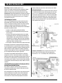
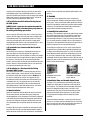
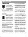
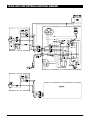
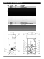
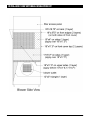
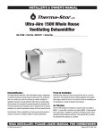
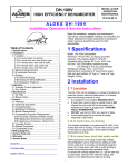
INSTALLER’S & OWNER’S MANUAL HVAC INSTALLER: PLEASE LEAVE MANUAL FOR HOMEOWNER Dehumidification The highly efficient Ultra-Aire 100V dehumidifier utilizes refrigeration to cool the incoming air stream below its dew point. This cooled and drier air is used to pre-cool the incoming air stream resulting in a significant increase in overall efficiency. After the pre-cooling stage, the processed air is reheated by passing through the condenser coil. The heat removed by the evaporator coil is returned to the air stream, resulting in an overall temperature increase of the air leaving the unit. The Ultra-Aire 100V is controlled by 24 volt remote wired controls. A variety of controls are available suitable to various applications. Fresh Air Ventilation Optional fresh outdoor air may be ducted to the unit via a six inch round duct. This provides fresh air to dilute pollutants and maintain high oxygen content in the air. The amount of fresh air ventilation can be regulated by a variety of dampers and controls. Air Filtration The UA-100V includes air filtration to improve indoor air quality. A MERV-11 media filter is standard. An optional MERV-14 deep pleated 95% media filter is available for optimum air filtration and to reduce potentially harmful airborne particles. If the optional filter is chosen, the standard filter operates as a prefilter. P/N 4022200 • Serial No.________________________ Install Date:___________ Sold by: P.O. Box 8680 Madison, WI 53708 • TOLL-FREE 1-800-533-7533 • www.thermastor.com • [email protected] © 2008 Therma-Stor LLC • Manual P/N TS-200L TABLE OF CONTENTS Table of Contents Safety Precautions Safety Precautions........................................................................ 2 1. Intended Application................................................................. 2 2. Specifications........................................................................... 2 3. Installation................................................................................ 3 3.1 Location............................................................................ 3 3.2 Electrical Requirements..................................................... 3 3.3 Condensate Removal......................................................... 3 3.4 Ducting.............................................................................. 3 3.4A Installing Duct Collars................................................. 3 3.4B Ducting for Dehumidification...................................... 3 3.4C Ducting for Fresh Air................................................... 4 3.4D Installation in a basement.......................................... 4 3.4E Installation in a attic................................................... 5 3.4F Installation with (2) HVAC systems.............................. 5 3.4G Installation without an HVAC system........................... 5 3.5 Quiet Installation................................................................ 5 4. Controls.................................................................................... 5 4.1 Humidity/Fan Control Panel................................................ 5 4.2 Ventilation Timer & Humidity Control Panel........................ 5 4.3 Humidity Control Adjustment............................................. 6 4.4 Fan/Filter Switch................................................................ 6 4.5 Ventilation Timer................................................................ 6 4.6 High Efficiency Air Filter..................................................... 7 Control Package Diagram Sheet.............................................. 8 5. DEH 3000/DEH 3000R Digital Control ...................................... 9 6. Maintenance........................................................................... 10 6.1 Standard Air Filter............................................................ 10 6.2 High Efficiency Air Filter................................................... 10 7. Service................................................................................... 10 7.1 Warranty . ....................................................................... 10 7.2 Technical description....................................................... 10 7.3 Troubleshooting .............................................................. 10 7.4 Refrigerant Charging....................................................... 11 7.5 Fan Replacement............................................................. 11 7.6 Compressor/Capacitor Replacement................................ 11 7.6A Checking Compressor Motor Circuits........................ 11 7.6B Replacing Burned Out Compressor........................... 12 7.6C Replacing Compressor-Nonburn Out........................ 12 7.7 Remote Controls.............................................................. 12 7.7A Humidity Control....................................................... 12 7.7B Ventilation Timer....................................................... 13 7.8 Defrost Thermostat.......................................................... 13 7.9 Electric Ventilation Damper.............................................. 13 Electrical Schematic................................................................... 14 Pictorial Electrical Diagram......................................................... 15 Service Parts List........................................................................ 16 Optional Parts List...................................................................... 17 External Insulation Kit................................................................. 18 Control Panel Installation............................................................ 19 Warranty..................................................................................... 20 Read the installation, operation and maintenance instructions carefully before installing and operating this device. Proper adherence to these instructions is essential to obtain maximum benefit from your Ultra-Aire indoor air quality system. Read and save these instructions • The device is designed to be installed INDOORS IN A SPACE THAT IS PROTECTED FROM RAIN AND FLOODING. • Install the unit with space to access the front panel for maintenance and service. DO NOT INSTALL UNIT WITH THE FRONT PANEL INACCESSIBLE. • Avoid directing the discharge air at people, or over the water in pool areas. • If used near a pool or spa; be certain there is NO chance the unit could fall into the water, splashed and that it is plugged into a GFCI GROUND FAULT CIRCUIT INTERRUPT OUTLET. • DO NOT use the device as a bench or table. • DO NOT place the device directly on structural members. • A drain pan MUST be placed under the unit if installed above a living area or above an area where water leakage could cause damage. 1. Intended Application for Ultra-Aire 100V For the ideal installation, draw air from the central part of the home and return it to isolated areas of the home like the bedrooms, den, utility room, or family room. The ductwork of the existing heating system can be used to supply air to the home. 2. Specifications Part Number: 4022200 Blower: 240 CFM @ 0.1" WG Supply Voltage: 115 Volt – 1 Phase – 60 Hz. Amps: 6.8 Energy Factor: 2.51 Operating Temp.: 56°F Min, 100°F Max Sized For: 2500 Square Foot Typical Minimum Performance at Set Conditions Intake Air: 80°F, 60% RH Capacity: 100 Pints/Day @ 80°F/60% RH Pints/kWh: 5.3 UA-100V Duct Connections: 6" Round Inlet , 8" Round Inlet, 8" Round Outlet Filter Efficiency:Standard MERV-11 (65% ASHRAE Dust Spot) Optional MERV-14 (95% ASHRAE Dust Spot) Power Cord: 9', 115V With Ground Drain Connection: .56" ID x 8’ Vinyl Hose UA-100V Dimensions: Unit Width:21" without collars, 24" with collars Height:42" without collars, 48" with collars Depth:17" Weight: 119 lbs 2 Shipping 30" 47" 25" 134 lbs Ultra-Aire 100V Installer’s & Owner’s Manual SAFETY PRECAUTIONS 3. Installation commonly available in 10' lengths from building supply, plumbing and hardware stores. It will slide tightly inside the end of the drain hose. If more than one length of pipe is required, they can be joined with a short piece cut from the end of the drain hose. 3.1 Location The Ultra-Aire should be located near the existing air handling system to minimize the required ductwork for connecting the Ultra-Aire to the existing air handling system.The controls for the Ultra-Aire are remote from the unit and must be located in the space that is to be conditioned. The controls are low voltage (24 volt) and should be connected to the Ultra-Aire with low voltage thermostat cable. An optional condensate pump may be installed if a lift is required to dispose of the condensate. The condensate pump kit can be ordered direct from the factory. See item 27 on page 21. 3.4 Ducting 3.4A Installing Duct Collars If fresh air ventilation is desired, thought should be given to the location for the fresh air ducting. A 6" round duct will have to be installed on the Ultra-Aire and run to the outside of the structure to bring in fresh air. Use an 8" insulated round duct for lengths of more than 25' or if more than 100 CFM is needed. The Ultra-Aire is equipped with 8" and 6" round inlet collars and an 8" round white exhaust collar. The 8" and 6" round inlet collars are designed with tabs that fold under the top of the Ultra-Aire. The 8" round white exhaust collar is attached to the Ultra-Aire by (4) screws. 3.2 Electrical Requirements To install the inlet collars: Insert the tabs of the collar into the hole in the top of the Ultra-Aire and fold the tabs up to attach to the Ultra-Aire. The Ultra-Aire plugs into a common grounded outlet on a 15 Amp circuit. It draws between 6 and 7 Amps under normal operating conditions. If used in a wet area (pool, spa room, or basement prone to flooding), a ground fault interrupter protected circuit is required. To install the exhaust collar: Bend the (4) tabs toward the inside of the collar 90°. Attach the collar to the Ultra-Aire cabinet using 1⁄2" long #8 sheet metal screws. DO NOT use screws longer than 1⁄2" to attach this collar or damage to the refrigeration system may result. The installer must supply the wiring between the Ultra-Aire and the control panel. Be sure to safely route the control wires to prevent damage during installation. Be careful not to cross the wires when connecting the Ultra-Aire and the remote control panel or damage to the transformer may result. 3.4B Ducting for Dehumidification For the ideal installation, draw air from the central part of the home and return it to the isolated areas of the home like the bedrooms, den, utility room, or family room. The ductwork of the existing heating system can be used to supply air to the home. If the existing supply goes to isolated areas of the home, discharge the supply of the Ultra-Aire into the supply of the existing heating system. If the existing heating system incorporates a central supply, installation of a separate supply duct from the Ultra-Aire to each isolated area is recommended. DO NOT draw air directly from the kitchen, laundry, or basement. All flexible ducting connected to the Ultra-Aire should be UL listed. The remote controls of the Ultra-Aire are powered by a low voltage circuit (24 Vac) and must NEVER contact or be connected to a high voltage circuit. The control wires leaving the Ultra-Aire and the remote control panels are color coded to prevent confusion. Some of the control wires leaving the Ultra-Aire may not be used with certain control panels and should be left safely disconnected with wire nuts taped onto the stripped ends. Be sure to consult the electrical schematic in this manual or on the front panel of the Ultra-Aire before making the control connections. Do not allow the yellow lead from the Ultra-Aire to contact the red lead or orange lead from the Ultra-Aire or damage to the transformer will result. The inlet of the Ultra-Aire is the 8" diameter hole on top of the unit. An 8" round collar is supplied with the unit to attach to round duct. The duct may be permanently attached to the collar. A 6" round collar is provided with the unit to attach to the 6" hole in the top. The 6" collar should be capped if fresh make-up air is not desired. If fresh make-up air is desired see section 3.4C. NOTE: Reset the ventilation timer before attempting to program after initial installation. The timer may not . . operate correctly until it is reset. The outlet of the Ultra-Aire is located on the side of the unit. A second 8" round collar is supplied with the unit and can be attached using the screws provided and the pre-punched holes in the cabinet side. WARNING! A length of 10 feet or more of acoustical flex ducting on the outlet of the Ultra-Aire will reduce air noise from the blower. A length of flexible ducting on all Ultra-Aire duct connections is recommended to reduce noise and vibration transmitted to rigid ductwork in the structure. 3.3 Condensate Removal Condensate drains by gravity via the clear hose extending from the unit. Route the hose to a floor drain. Use care to keep the hose as flat to the floor as possible; excessive humps will prevent proper drainage. We do not call for a trap since there is an internal trap with this unit. If the Ultra-Aire is located too far from a floor drain for the attached hose to reach, inexpensive 1⁄2" PVC pipe can be used to extend it. It is Ducting the Ultra-Aire as mentioned in sections 3.4A-3.4G requires consideration of the following points: 3 Ultra-Aire 100V Installer’s & Owner’s Manual FOR HVAC INSTALLER ONLY Duct Sizing: For total duct lengths up to 25', use a minimum 8" diameter round or equivalent rectangular. For longer lengths, use a minimum 10" diameter or equivalent. Grills or diffusers on the duct ends must not excessively restrict air flow. structure. Do not use a return from a room that may have its door closed much of the time. Basement Installation: Locate a separate return for the Ultra-Aire in a central area of the structure. Duct the supply of the Ultra-Aire to a 8" x 8" x 8" tee/damper that is 30% open to the basement. Duct the other side of the tee to the air return of the existing HVAC system. If the existing HVAC system has a central return, duct the other side of the tee to the air supply of the existing HVAC system. Connect a duct from outside to the 6" collar of the Ultra-Aire if you wish to provide fresh make-up air. Isolated Areas: Effective dehumidification may require that ducting be branched to isolated, stagnant areas. Use 6" or larger diameter branch ducting to each of two or three areas; use 4" or larger to each of four or more areas. 3.4C Ducting for Fresh Air Fresh air can be brought into the structure by connecting a duct from outside to the 6" Ultra-Aire inlet and by turning on the fan switch or activating the humidity control on units with the humidity control panel. Activate the ventilation timer on units with the ventilating & humidity control panel to bring in fresh air. Advantages of this form of ventilation include: 1. Outside air is filtered before entering the building. 2. Outside air will be dehumidified before entering if the UltraAire is running. 3.Drawing air from outside and blowing inside aids in slightly pressurizing the structure. This helps prevent unfiltered and undehumidified air from entering elsewhere. It also reduces the potential for carcinogenic radon gas to enter and provides makeup air for open combustion and exhaust devices like the clothes drier, fireplace, and water heater. 4.The need for an alternate ventilation device may be eliminated. An insulated 6" diameter duct is generally sufficient to provide up to 125 CFM of outside air. Large quantities of outside air will impact Ultra-Aire performance positively or negatively, depending upon the difference between inside and outside air conditions. Consult the factory by calling 1-800-533-7533 for recommendations regarding the use of higher flows with your specific application. Crawlspace Installation: Locate a separate return for the UltraAire in a central area of the structure. Duct the supply of the Ultra-Aire to a 8" x 8" x 8" tee/damper that is 30% open to the The outside air duct should be connected to the 6" round collar on top of the unit. The 6" round collar includes a manual damper. Adjust the manual damper to provide the desired amount of fresh air for ventilation. The amount of fresh air should be based on the size and occupancy of the residence. If you are unsure of your ventilation air requirements, consult the factory by calling 1-800-533-7533 for assistance. 3.4D Installation in a Basement or Crawlspace with an Existing Forced Air HVAC System. If the structure in which the Ultra-Aire is to be installed has an existing forced air HVAC system, utilize the HVAC system to make the Ultra-Aire installation easier. If the existing system has multiple returns, select one to disconnect from the existing forced air system and use it for the dedicated Ultra-Aire return. Always select a return from a central location in the structure in an area that is always open to the rest of the 4 Ultra-Aire 100V Installer’s & Owner’s Manual FOR HVAC INSTALLER ONLY crawlspace. Duct the other side of the tee to the air return of the existing HVAC system. If the existing HVAC system has a central return, duct the other side of the tee to the air supply of the existing HVAC system. Connect a duct from outside to the 6" collar of the Ultra-Aire if you wish to provide fresh make-up air. to reduce noise and vibration transmitted to rigid ductwork in the structure. 4. Controls The Ultra-Aire can be equipped with various accessories to enhance its operation. A remote control panel must be used with the Ultra-Aire . There are two remote control panels from which to choose. The humidity/fan control panel is used to control humidity and the fan. The ventilation timer and humidity control panel is used to control ventilation, humidity and the fan. 3.4E Installation in an Attic with an Existing Forced Air HVAC System ALWAYS install a catch pan for condensate under the Ultra-Aire in an attic or condensate may drip down on the ceiling of the living space below. 4.1 Humidity/Fan Control Panel See Figure 1: The humidity/fan control panel automatically controls the humidity of the living space. The humidity/fan control panel contains an adjustable humidity control and a fan switch. This panel should be mounted in a central area of the structure where it can accurately sense the humidity of the air in the living space. The panel has small perforations that must remain open to the air within the living space for accurate humidity sensing. Locate a separate return for the Ultra-Aire in a central area of the structure. Duct the supply of the Ultra-Aire to the air supply of the existing HVAC system. If the existing HVAC system has a central return, duct the supply of the Ultra-Aire to the air supply of the existing HVAC system. Connect a duct from outside to the 6" collar of the Ultra-Aire if you wish to provide fresh make-up air. 3.4F Installation in a Structure with Two Forced Air HVAC Systems The humidity/fan control panel can be used in conjunction with the optional fresh air damper. When used with the optional fresh air damper, the fan/filter switch will act as a fresh air ventilation control. When the switch is ON (in this configuration), the fan will run, the fresh air damper will open, and fresh air will be filtered and brought into the structure. When the switch is OFF, the fresh air damper will close and the fan will operate only when the humidity control calls for dehumidification. Attach the Ultra-Aire return to to a independent return from the upper level. Attach the Ultra-Aire supply to the supply of the basement HVAC system. This will promote circulation of air through the whole structure from the upper level to the lower level through the Ultra-Aire . If the Ultra-Aire is not connected to both HVAC systems, it will not control the humidity and ventilation of the entire structure. Connect a duct from outside to the 6" collar of the UltraAire if you wish to provide fresh make-up air. 3.4G Installation in a Structure with No Existing Forced Air HVAC Systems When installing the Ultra-Aire in a structure that does not have a forced air HVAC system, a single return for the Ultra-Aire should be installed in central open area of the structure. DO NOT locate the return in a bathroom or a kitchen. The supply of the UltraAire should be located in the remote areas of the structure (such as bedrooms, den, etc.). By ducting this way the air inside the structure will circulate through the Ultra-Aire to be filtered and dehumidified. Connect a duct from outside to the 6" collar of the Ultra-Aire if you wish to provide fresh make-up air. Figure 1: Humidity/Fan Control Panel Part No. 4024155 Figure 2: Ventilation Timer and Humidity Control Panel Part No. 4024125 4.2 Ventilation Timer and Humidity Control Panel See Figure 2: The ventilation timer and humidity control panel automatically controls both the ventilation and the humidity of the living space. The ventilation timer and humidity control panel contains an adjustable humidity control, a fan switch, and a ventilation timer. This panel will control the humidity and allow programmed ventilation of the living space. This panel works in conjunction with the optional fresh air damper to provide ventilation. 3.5 Quiet Installation Loosen the compressor mounting bolts from the base of the unit. Do not remove the bolts, but loosen them so the compressor mounting grommets are not compressed. These bolts are tightened at the factory to prevent damage during shipping. Loosening them will reduce the amount of compressor vibration. Make sure none of the compressor tubes are pressed against the cabinet or front panel. This panel should be mounted in a central area of the structure where it can accurately sense the humidity of the air in the living space. The panel has small slots that must remain open to the air within the living space for accurate humidity sensing. A length of 10 feet or more of acoustical flex ducting on the outlet of the Ultra-Aire will reduce air noise from the blower. A length of flexible ducting on all Ultra-Aire duct connections is recommended 5 Ultra-Aire 100V Installer’s & Owner’s Manual FOR HVAC INSTALLER ONLY 4.3 Humidity Control Adjustment If the timer fails to operate or operates erratically, check that the control panel receives 24Vac from the Ultra-Aire . If 24Vac is present at the control panel, reset the timer by pressing the reset button at the bottom center of the timer face. The reset button is the small recessed button with an R beneath it located below the 1…7 and h buttons. Press the reset button in until the display disappears. Release the reset button. The display will reappear as 00:00. Resetting the timer will clear the time and all program settings. After resetting the timer, follow the instructions below to set the correct time and ventilation programs. Set the humidity control to the desired humidity level for the home. The dehumidifier will run continuously until the relative humidity (RH) is reduced to the humidity control dial setting. Setting the humidity control to lower RH levels will NOT increase the unit's dehumidification rate; the unit will simply run longer to reduce the area's RH to the setting. The Ultra-Aire unit (and refrigerant based Figure 3 dehumidifiers in general) will reduce a warm Humidity Control space's RH to a lower level than that of a Adjustment Knob cool space. It is therefore pointless to set the humidity control to excessively low levels in cool rooms; doing so will result in long periods of ineffective dehumidifier run time. The following instructions explain how to set the ventilation timer. First, set the correct time on the timer by sliding the switch in the upper right hand corner of the timer to the clock symbol + and pressing the 1…7 (DAY), h (HOUR), and m (MINUTE) buttons. Remember that this timer operates on a 24-hour (military time) clock. Quality humidity meters are available from the factory and are recommended to accurately monitor humidity levels. 4.4 Fan/Filter Switch Next, set the ventilation time schedule. Slide the switch in the upper right hand corner to the program symbol P “ON” will appear to the right of the time and the number “1” will appear in the lower right hand corner of the display. The “1” and “ON” signify the turn on time for the first program. Press the 1…7 button to choose the days of the week for this program. You can choose Mon-Sun Mon-Fri, Sat-Sun, or any single day of the week. The days chosen are shown along the top of the display on the ventilation timer. Next press the h button to set the hour for the start of the ventilation period. Remember that this timer operates on a 24-hour clock. Then press the m button to set the minutes past the hour to start the ventilation. Now, with the ventilation start time set, press the I/O button. The word “OFF” should appear to the right of the time and the number “1” should remain in the lower right hand corner of the display. The “1” and “OFF” signify the turn off time for the first program. Set the turn off time using the 1…7, h, and m buttons in the same way as described above and continue on to the second through sixth programs. When setting the ventilation programs, you can return to the current time display by sliding the switch in the upper right corner of the timer to RUN. The slide switch in the upper right must be set to RUN for the timer to operate with the scheduled programs. Turning ON the fan/filter switch will cause the central conditioning unit's internal fan to run continuously, whether the central conditioning unit is dehumidifying or not. This function is desirable if the central conditioning unit is used for air circulation and filtration. When the switch is ON, air will be constantly filtered through the central conditioning unit and circulated throughout Figure 4 the house. When the switch is OFF, the fan Fan/Filter Switch will operate only when the humidity control calls for dehumidification or when the ventilation timer calls for ventilation. 4.5 Ventilation Timer The ventilation timer controls the fan and the motorized fresh air damper. When the ventilation timer is activated, the central conditioning unit will circulate the indoor air, and bring in fresh air from outside. The ventilation timer should be set for the required ventilation of the residence. The home should be ventilated with fresh air whenever it is occupied. The ventilation timer is an electronic timer that displays the current time. This timer has a battery backup, so it will not require resetting after a power outage. The one minute time increments of the ventilation timer allow you to program the ventilation of your home to fit your schedule. The slide switch in the upper left of the timer is used to choose between automatic and manual operation of the timer relay. When the slide switch in the upper left of the timer is set to AUTO mode, the central conditioning unit will ventilate when the scheduled programs call for ventilation. When the slide switch in the upper left of the timer is set to manual (set to hand symbol on the the right), the operation of the timer is controlled by the I/O button only. Pressing the I/O button will switch the ventilation timer between ON (detent) and OFF (detent). As you press the I/O button, “ON” or “OFF” will be displayed to the right of the time. The “ON” or “OFF” The ventilation timer has six programs with each program having one “on” and one “off” event. A program allows the user to turn the ventilation on at a certain day and time, then it allows them to turn the ventilation off at a certain day and time. Each of these programs can be repeated daily or weekly or during a specified block of days. All six of the programs operate independently of each other. 6 Ultra-Aire 100V Installer’s & Owner’s Manual FOR HVAC INSTALLER ONLY to the right of the time will indicate if the ventilation timer is on or off. The I/O button will manually override scheduled programs if the timer is in AUTO mode. 4.6 High Efficiency Air filter A high efficiency air filter is available for the Ultra-Aire . This filter is rated 90%-95% efficient by ASHRAE Dust Spot Test Method 52-76. This filter is much more efficient than the standard air filter and is able to catch much smaller particles that can aggravate allergies. The high efficiency air filter is 4 inches thick and should be installed in the filter enclosure directly below the standard air filter. The standard air filter will act as a pre-filter for the high efficiency air filter and will prolong the life of the high efficiency air filter. 7 Ultra-Aire 100V Installer’s & Owner’s Manual ATTENTION INSTALLER WIRE THE UNIT AND CONTROL PACKAGE AS SHOWN IN THE DIAGRAM BELOW Humidity/Fan Control Panel Ventilation Timer/ Humidity Control Panel DEH 3000 Digital Control (P/N 4028539; with remote: P/N 4028407) WARNING: DO NOT allow the yellow lead from the unit to contact the red lead or the white lead from the unit or damage to the transformers will result. Do not direct connect the white lead on the unit to the violet lead on the ventilation control or damage to the transformer will result. 8 Ultra-Aire 100V Installer’s & Owner’s Manual DEH 3000/DEH 3000R DEH 3000, DEH 3000R DEHUMIDIFIER & VENTILATION SYSTEM CONTROLLER DEH 3000/DEH 3000R Part No. 4028539 Part No. 4028407 5. Optional Dehumidifier & Ventilation System Controller Major Operations When used with Ultra-Aire Whole House Ventilating Dehumidifiers, the DEH 3000/3000R allows homeowners the ability to monitor and control relative humidity levels in their home. n Digital control of Relative Humidity (Digital Set-Point) n Fan/Filter Operation n Programmable Ventilation Timer n Large, easy-to-read backlit LCD display DEH3000 P/N: 4028539 n Easy interaction with air handler fan (Interlock/Lockout) DEH3000R (remote) P/N: 4028407 n High Temperature Cut-Out Model: DEH 3000 DEH 3000R (remote) n Dryout Cycle Timer n Auto Reboot Operating Voltage: 24 VAC n Remote Sensor (DEH 3000R Only) Max Current DMP, COMP, FAN: 1 AMP each Humidity Range/Accuracy: 10 – 95% RH, ± 5% Auxillary Relay Capacity: 5 Amps, 24VAC Temp Range/Accuracy: 30°-90°F, 2% Size: 4.95"L x 1.06"W x 4.19"H To order call Therma-Stor at 1-800-533-7533 9 Ultra-Aire 100V Installer’s & Owner’s Manual FOR HVAC INSTALLER AND HOMEOWNER 6. Maintenance 7. Service CAUTION: Servicing the Ultra-Aire with its high pressure refrigerant system and high voltage circuitry presents a health hazard which could result in death, serious bodily injury, and/or property damage. Only qualified service people should service this unit. 6.1 Standard Air Filter The Ultra-Aire is equipped with a pleated cloth air filter. This filter should be checked monthly. Operating the unit with a dirty filter will reduce dehumidifier capacity and efficiency and may cause the compressor to cycle off and on unnecessarily on the defrost control. To access the air filter, remove a filter access panel from one end of the Ultra-Aire. To remove the filter access panel from the UltraAire, pull the panel straight up about 1⁄2" until the bolt heads near the bottom of the panel are centered in the larger opening of the keyhole slots. Next rock the bottom of the access panel away from the Ultra-Aire and lift the access panel straight up to remove the tab on top of the panel from the slot in the top of the Ultra-Aire. The filter should be readily visible and can be removed by pulling it straight out of the Ultra-Aire. 7.1 Warranty A warranty certificate has been enclosed with this unit; read it before any repair is initiated. If a warranty repair is required, call the factory first at 1-800-533-7533 for warranty claim authorization and technical assistance. 7.2 Technical Description The Ultra-Aire uses a refrigeration system similar to an air conditioner's to remove heat and moisture from incoming air, and add heat to the air that is discharged (See Figure 3). The pleated cloth filter can generally be vacuumed clean several times before needing replacement. Replacement filters can be ordered from the factory or purchased locally if available. DO NOT operate the unit without the standard filter or with a less effective filter than the standard filter; the heat exchange coils inside the unit could become clogged and require disassembly to clean. Hot, high pressure refrigerant gas is routed from the compressor to the condenser coil (See Figure 3). The refrigerant is cooled and condensed by giving up its heat to the air that is about to be discharged from the unit. The refrigerant liquid then passes through a filter/drier and capillary tubing which cause the refrigerant pressure and temperature to drop. It next enters the evaporator coil where it absorbs heat from the incoming air and evaporates. The evaporator operates in a flooded condition, which means that all the evaporator tubes contain liquid refrigerant during normal operation. A flooded evaporator should maintain constant pressure and temperature across the entire coil, from inlet to outlet. 6.2 High Efficiency Air Filter An optional high efficiency pleated microglass paper filter is available for the Ultra-Aire. This filter is rated as 90%-95% efficient by the ASHRAE Dust Spot test method 52-76. The high efficiency pleated microglass paper filter should be used in conjunction with the standard filter, and placed directly beneath the standard filter. This filter is able to remove allergy causing particles from the airstream. The high efficiency filter has a much larger surface area than the standard filter, thus the standard filter may need to be cleaned or replaced several times before the high efficiency filter requires replacement. Be careful not to damage the fabric media when handling the high efficiency pleated paper filter. Do not attempt to clean the high efficiency pleated paper filter. It should be replaced when it becomes restrictive (See Figure 7). The mixture of gas and liquid refrigerant enter the accumulator after leaving the evaporator coil. The accumulator prevents any liquid refrigerant from reaching the compressor. The compressor evacuates the cool refrigerant gas from the accumulator and compresses it to a high pressure and temperature to repeat the process. 7.3 Troubleshooting No dehumidification, neither fan nor compressor run with fan switch and ventilation timer OFF. 1. Unit unplugged or no power to outlet. 2. Humidity control set too high or defective (Sec. 3.3 & 5.7A) 3. Loose connection in internal or control wiring. 4. Defective Compressor relay. 5. Defective control transformer. 10 Ultra-Aire 100V Installer’s & Owner’s Manual FOR HVAC INSTALLER AND HOMEOWNER No dehumidification, compressor does not run but fan runs with fan switch and ventilation timer OFF and humidity control turned to ON. 1. Defective compressor run capacitor (Sec. 5.6). 2. Loose connection in compressor circuit (See Fig. 4). 3. Defective compressor overload (Sec. 5.6A). 4. Defective compressor (Sec. 5.6). 5. Defrost thermostat open (Sec. 5.8). left in the system, it must be recovered before weighing in the new charge. Refer to the unit nameplate for the correct charge weight and refrigerant type. 7.5 Fan Replacement The centrifugal fan has a PSC motor and internal thermal overload protection. If defective, the complete assembly must be replaced. 1. Unplug the power cord. 2. If an outlet duct is connected to the unit, remove it. 3. Remove the cabinet side. 4.Remove the 3 screws attaching the electrical box located in front of the fan to the base. 5.Disconnect the fan leads. Black from the fan relay and white from the run capacitor. 6.Remove the nuts & bolts holding the fan outlet flange to the cabinet end and remove the fan. 7. Reassemble the new fan by reversing the above procedure. Fan runs with fan switch and ventilation timer OFF, but compressor cycles on & off. 1.Low ambient temperature and/or humidity causing unit to cycle through defrost mode. 2. Defective compressor overload (Sec. 5.6A). 3. Defective compressor (Sec. 5.6). 4. Defrost thermostat defective (Sec. 5.8). 5. Dirty air filter(s) or air flow restricted. 7.6 Compressor/Capacitor Replacement Fan does not run with fan switch in either position. Fan does not run with ventilation timer activated. Compressor runs briefly but cycles on & off with humidity control turned to ON. 1. Loose connection in fan circuit (See Fig. 4). 2. Obstruction prevents fan impeller rotation. 3. Defective fan. 4. Defective fan relay. This compressor is equipped with a two terminal external overload and a run capacitor, but no start capacitor or relay (See Figure 4). CAUTION-ELECTRICAL SHOCK HAZARD: Electrical power must be present to perform some tests. These tests should be performed by a qualified service person. Fan runs with fan switch ON. Fan does not run with ventilation timer activated. 1. Defective ventilation timer. 2. Time not correct on ventilation timer. 3. Ventilation timer set to manual & switched OFF. 7.6A Checking Compressor Motor Circuits Perform the following tests if the fan runs but the compressor does not with the fan switch OFF and the humidity control ON. 1.Unplug the unit, remove the cabinet side and the electrical connection cover on the compressor top. 2. Plug in the unit and turn the humidity control to ON. Check for 110 volts from compressor terminal R to overload terminal 3 using an AC voltmeter. If voltage is present, go to step 3. If no voltage, there may be a loose connection in the compressor circuit. Test each component for continuity. See the appropriate section if a defect is suspected. 3. Unplug the unit, then disconnect the red and yellow wires from compressor terminals R & S. Using an ohmmeter, check continuity between the points listed below. 4. Compressor terminals C and S: No continuity indicates an open start winding. The compressor must be replaced. Normal start winding resistance is 3 to 7 ohms. 5. Compressor terminals C and R: No continuity indicates an open run winding. The compressor must be replaced. Normal run winding resistance is .5 to 2 ohms. Evaporator coil frosted continuously, low dehumidifying capacity. 1. Defrost thermostat loose or defective (Sec. 5.8). 2. Low refrigerant charge 3. Dirty air filter(s) or air flow restricted. 4. Excessively restrictive ducting connected to unit. Unit not providing ventilation. Ventilation timer notoperating correctly. 1.If timer is not functioning correctly, reset timer and reprogram (Sec. 3.5) 2.Check control wire connections (check connections at damper also) 3. Defective fresh air damper (Sec. 5.9) 7.4 Refrigerant Charging If the refrigerant charge is lost due to service or a leak, a new charge must be accurately weighed in. If any of the old charge is 11 Ultra-Aire 100V Installer’s & Owner’s Manual FOR HVAC INSTALLER AND HOMEOWNER 6. Compressor terminal C and overload terminal 1: No continuity indicates a defective overload lead. 7. Overload terminals 1 and 3: If there is no continuity, the overload may be tripped. Wait 10 minutes and try again. If there is still no continuity, it is defective and must be replaced. 8. Compressor terminal C and compressor case: Continuity indicates a grounded motor. The compressor must be replaced. 9. Disconnect the wires from the run capacitor. Set the ohmmeter to the Rx1 scale. The capacitor is shorted and must be replaced if continuity exists across its terminals. If there is no needle movement with the meter set on the Rx100000 scale, the capacitor is open and must be replaced. 10. Reconnect the wires to the compressor and capacitor. Plug in and turn on the unit. If the compressor fails to start, replace the run capacitor. 11.If the unit still does not start, adding a hard-start kit (relay & capacitor) will provide greater starting torque. If this doesn't work, the compressor has an internal mechanical defect and must be replaced. compressor was not rotating. Contaminants are therefore largely confined to the compressor housing. A single installation of liquid and suction line filter/driers will probably clean up the system. If sludge is evident in the discharge line, it will likely be found in the suction line. This indicates the compressor burned out will running. Sludge and acid have been pumped throughout the system. Several changes of the liquid and suction filter/driers will probably be necessary to cleanse the system. 5. Correct the system fault that caused the burn out. Consult the factory for advice. 6. Install the replacement compressor with a new capacitor and an oversized liquid line filter. In a running burn out, install an oversized suction line filter/drier between the accumulator and compressor. Thoroughly flush the accumulator with refrigerant to remove all trapped sludge and to prevent the oil hole from becoming plugged. A standing burn out does not require a suction line filter/drier. 7. Evacuate the system with a good vacuum pump and accurate vacuum gauge. Leave the pump on the system for at least an hour. 7.6B Replacing a Burned Out Compressor 8. Operate the system for a short period of time, monitoring the suction pressure to determine that the suction filter is not becoming plugged. Replace the suction filter/drier if pressure drop occurs. If a severe running burn out has occurred, several filter/driers may have to be replaced to remove all of the acid and moisture. The refrigerant and oil mixture in a compressor is chemically very stable under normal operating conditions. However, when an electrical short occurs in the compressor motor, the resulting high temperature arc causes a portion of the refrigerant oil mixture to break down into carbonaceous sludge, a very corrosive acid, and water. These contaminants must be carefully removed otherwise even small residues will attack replacement compressor motors and cause failures. NOTE: NEVER use the compressor to evacuate the system or any part of it. 7.6C Replacing a Compressor, Nonburn Out The following procedure is effective only if the system is monitored after replacing the compressor to insure that the clean up was complete. Remove the refrigerant from the system. Replace the compressor and liquid line filter/drier. Charge the system to 50 PSIG and check for leaks. Remove the charge and weigh in the refrigerant quantity listed on the nameplate. Operate the system to verify performance. 1. This procedure assumes that the previously listed compressor motor circuit tests revealed a shorted or open winding. If so, cautiously smell the refrigerant from the compressor service port for the acid odor of a burn out. WARNING: The gas could be toxic and highly acidic. If no acid odor is present, skip down to the section on changing a non-burn out compressor. 7.7 Remote Controls The Ultra-Aire is controlled by devices mounted on a panel that is remote from the unit. You may or may not have the devices listed below depending on the model of the remote control panel that you purchased. If the Ultra-Aire fails to operate as desired, always check the settings of the controls to insure that they are correct. Check that the controls are receiving 24Vac from the Ultra-Aire. Check the connections between the Ultra-Aire, the control panel, and the field control wiring. 2. Remove and properly dispose of the system charge. DO NOT vent the refrigerant indoors or allow it to contact your eyes or skin. 3. Remove the burned out compressor. Use rubber gloves if there is any possibility of contacting the oil or sludge. 7.7A Humidity Control 4. To facilitate subsequent steps, determine the type of burn out that occurred. If the discharge line shows no evidence of sludge and the suction line is also clean or perhaps has some light carbon deposits, the burn out occurred while the The humidity control is an adjustable switch that closes when the relative humidity of the air in which it is located rises to the dial set point. It opens when the RH drops 4 to 6% below the set point. If the 12 Ultra-Aire 100V Installer’s & Owner’s Manual FOR HVAC INSTALLER AND HOMEOWNER 7.9 Electric Ventilation Damper Ultra-Aire does not run, try turning the humidity control clockwise until it reaches the stop and the knob pointer points at “ON”. The electric ventilation damper is controlled by the ventilation timer. The damper will open when the ventilation timer is activated to allow fresh air into the structure through the 6" diameter fresh air inlet duct. The electric ventilation damper will remain closed when the ventilation timer is not activated to prevent over-ventilating the structure when the unit is dehumidifying or recirculating the indoor air. The Ultra-Aire is equipped with a automatic defrost mechanism. If the Ultra-Aire operates in conditions that develop frost on the evaporator, it will sense the frost build-up and automatically defrost the evaporator. The Ultra-Aire may not appear to be operating correctly during the defrost sequence, but once the defrost is completed, the Ultra-Aire will resume dehumidifying. The electric ventilation timer operates on 24 Vac from the control circuit. DO NOT connect high voltage to the damper motor or damage to the motor may result. DO NOT force the blade of the damper by hand or damage to the damper motor may result. 7.7B Programmable Ventilation Timer The ventilation timer controls the fan and the motorized fresh air damper. When the ventilation timer is activated, the central conditioning unit will circulate the indoor air, and bring in fresh air from outside. The ventilation timer should be set for the required ventilation of the residence. The home should be ventilated with fresh air whenever it is occupied. If the Ultra-Aire fails to ventilate as expected, check that the time on the timer is correct. For the timer to carry out the program schedule, the slide switch in the upper left corner on the timer must be set to “AUTO”. The slide switch in the upper right corner of the Ultra-Aire must be set to “RUN”. Also check the programs on the timer to be sure that the timer is calling for ventilation at the correct times. If the timer fails to operate or operates erratically, reset the timer; see section 3.5 of this manual. The damper opens in one direction only. The damper rotates very slowly, allow sufficient time for the damper to cycle. The damper will take approximately 1 minute to cycle from closed to open or from open to closed. If the electric ventilation damper fails to operate: 1. Check that the wiring is correct and that voltage is present at the damper motor. 2. Check for any obstruction inside the damper. If the electric ventilation damper fails to operate after performing these checks, it must be replaced. 7.8 Defrost Thermostat The defrost thermostat is attached to the refrigerant suction tube between the accumulator and the compressor. It will automatically shut the compressor off if the low side refrigerant temperature drops due to excessive frost formation on the evaporator coil. The fan will continue to run, causing air to flow through the evaporator coil and melt the ice. When the ice has melted, the evaporator temperature will rise and the thermostat will restart the compressor. 13 Ultra-Aire 100V Installer’s & Owner’s Manual ULTRA-AIR 100V ELECTRICAL SCHEMATIC 14 Ultra-Aire 100V Installer’s & Owner’s Manual ULTRA-AIRE 100V PICTORIAL ELECTRICAL DIAGRAM 15 Ultra-Aire 100V Installer’s & Owner’s Manual ULTRA-AIRE 100V SERVICE PARTS LIST Item Part No. QTY. Description 1 2 3 4 5 6 7 8 9 10 11 12 13 14 15 16 17 18 19 20 21 22 1 1 1 1 2 1 1 1 1 1 1 1 1 1 1 1 1 1 1 1 4 1 1 Accumulator Air Filter, Pleated Cloth Fan (Blower) w/ Capacitor Evaporator Coil Capillary Tubes, .050" ID x .114 OD x 28" long Collar, Inlet, 8" Galvanized Steel Collar, Inlet, 6" Galvanized Steel with Damper Collar, Outlet, 8" White (for outlet only) Compressor, Panasonic (2R12S3R126A-6A) Compressor Overload (TI # MRA98706-673) (not shown) Condenser Coil Cord & Wire Harness Filter/Drier Hose, Drain Pan, .56" ID x 8' Relay, SPST, 24 Vac, 30A Relay, SPDT, 24 Vac, 15A Run Capacitor for Compressor, 35 MFD, 440v Thermostat, Defrost Thermostat Clip, Defrost (item 18) (not shown) Transformer, 120/24 Vac, 40 VA Wheel, 2", Plastic Wire Harness, Low Voltage Wiring Diagram (on Cover — not shown) 4022254 4021475 4026930 4021395 4021589 4023875 4023928 4020623 4022147 4022144 4021396 4022445 4025087 4021626 4022484 4020924 4024666 4021470 4021648 4022487 4021471 4022444 4022442 16 Ultra-Aire 100V Installer’s & Owner’s Manual ULTRA-AIRE 100V OPTIONAL PARTS LIST Item Part No. QTY. 26 27 28 29 30 31 32 33 34 35 36 37 38 39 40 41 41a 4022489 4022220 4024155 4024125 4023660 4023672 4024153 4021495 4024150 4024122 4025560 4022486 4022443 4022474 4023647 4028539 4028407 1 1 1 1 1 1 1 1 1 1 1 1 1 1 1 1 1 Description Air Filter, High Efficiency, Pleated Microglass Paper, 90%-95% Condensate Pump Kit Control Panel Assembly, Humidity/Fan Control Panel Assembly, Ventilation Timer & Humidity Controller, Humidity Damper, Duct, 6" Diameter, Electrically Actuated (not shown) Cover for Items 28 & 29 (not shown) Knob, Black, .25" shaft Instructions, Humidity/Fan (not shown) Instructions, Ventilation Timer & Humidity (not shown) Switch, Black, SPDT, ON/OFF Timer, 7-Day, 24 Vac, Programmable Wire Harness, Ventilation Timer & Humidity (not shown) Wire Harness, Humidity/Fan (not shown) Damper, Check, 8" Diameter (not shown) DEH 3000 Digital Controller (not shown) DEH 3000R Digital Controller (not shown) 17 Ultra-Aire 100V Installer’s & Owner’s Manual ULTRA-AIRE 100V EXTERNAL INSULATION KIT 18 Ultra-Aire 100V Installer’s & Owner’s Manual ULTRA-AIRE 100V CONTROL PANEL INSTALLATION 1. T he following installation instructions are for both new construction and retrofit applications. For new construction, it is recommended that the control box be installed after the drywall is in. Prior to drywall installation, the control wires can be positioned to come through the drywall about 5' 2" above the floor and at least 3" left or right of any stud. 2. L ocate the box bottom about 5' above the floor. Locate the left and right box sides at least 2" from any stud. Use the back of the control box as a template to make the rectangular drywall cutout (5-13/16" wide by 4-1/16" high). DO NOT oversize the cutout, especially the height. 3. F eed the low voltage control wires into the box back through the rubber grommet. 4. P lace the box in the hole and put the mounting tabs through the slots in the box sides as shown. 5. P lace the two 3⁄4" long, #8 screws through the tab slots and into the holes in the box sides. 6. T ighten the screws until the tab ears press firmly against the drywall back, causing the upper and lower box flanges to press tightly against the drywall front. 7. C onnect the control wires to the control panel leads per the installation sheet taped to the Ultra-Aire side or per the manual. 8. F asten the control panel to the box flanges with the 1⁄2" long, #6 screws provided. 9. S lide the cover over the control panel screw head at the panel top so it catches in the keyhole on the back of the cover (see detail below). The cover hides the control panel when it is not being programmed. 10. The sheet under the cover glass can be replaced with artwork of the customers’ choice. 19 Ultra-Aire 100V Installer’s & Owner’s Manual Limited Warranty Limited Warranty. Therma-Stor, LLC (“Therma-Stor”) warrants as follows: (i) the Santa Fe Rx dehumidifier (“Product”) will be free of material defects in workmanship or materials for a period of three (3) years (“Three-Year Warranty”) following the date of initial purchase of such Product by an original customer purchasing from ThermaStor or an authorized reseller (“Customer”); and (ii) the Product’s condenser, evaporator, and compressor will be free of material defects in workmanship or materials for a period of five (5) years following the date of initial purchase of such Product by a Customer. Limitation of Remedies. CUSTOMER’S SOLE AND EXCLUSIVE REMEDY UNDER THE ABOVE LIMITED WARRANTY AND THERMASTOR’S ENTIRE LIABILITY THEREUNDER, SHALL BE, AT THE SOLE OPTION OF THERMA-STOR, REPLACEMENT OR REPAIR OF SUCH PRODUCT OR ITS COMPONENTS (“COMPONENTS”) BY THERMASTOR OR THERMA-STOR’S AGENTS ONLY. REFRIGERANT, PIPING, SUPPLIES, TRANSPORTATION COSTS, LABOR COSTS INCURRED IN REPAIR OR REPLACEMENT OF SUCH COMPONENTS ARE NOT INCLUDED. THIS DISCLAIMER AND EXCLUSION SHALL APPLY EVEN IF THE EXPRESS WARRANTY AND LIMITED REMEDY SET FORTH HEREIN FAILS OF ITS ESSENTIAL PURPOSE. CUSTOMER ACKNOWLEDGES THAT NO REPRESENTATIVE OF THERMA-STOR OR OF ITS AFFILIATES OR RESELLERS IS AUTHORIZED TO MAKE ANY REPRESENTATION OR WARRANTY ON BEHALF OF THERMA-STOR OR ANY OF ITS AFFILIATES OR RESELLERS THAT IS NOT IN THIS AGREEMENT. Notwithstanding the above, during the term of the Three-Year Warranty only, Therma-Stor will provide, free of charge to Customer, all Components and labor (except costs related to removal and installation of Product) required to fulfill its obligations under such Three-Year Warranty. Disclaimer of Warranties. EXCEPT FOR ABOVE LIMITED WARRANTY, WHICH IS THE SOLE AND EXCLUSIVE WARRANTY PROVIDED WITH RESPECT TO THE PRODUCT AND ITS COMPONENTS, THERMA-STOR HEREBY DISCLAIMS ALL EXPRESS AND IMPLIED WARRANTIES, INCLUDING, WITHOUT LIMITATION, THE IMPLIED WARRANTIES OF MERCHANTABILITY AND FITNESS FOR A PARTICULAR PURPOSE. Warranty Limitations. The foregoing limited warranty extends only to a Customer and shall be null and void upon attempted assignment or transfer. A “defect” under the terms of the limited warranty shall not include problems resulting from Customer’s or Customer’s employees’, agents’, invitees’ or a third party’s misuse, improper installation, improper design of any system in which the Product is included, abuse, lack of normal care, failure to follow written instructions, tampering, improper repair, or freezing, corrosion, acts of nature or other causes not arising out of defects in Therma-Stor’s workmanship or material. If a Product or Component is replaced while under warranty, the applicable limited warranty period shall not be extended beyond the original warranty time period. The limited warranty does not cover any costs related to changes to a Product or Component that may be required by any codes, laws, or regulations that may become effective after initial purchase of the Product by Customer. Customer Responsibilities. As a further condition to obtaining warranty coverage hereunder, the Customer must send a valid warranty claim to Therma-Stor such that Therma-Stor receives such claim prior to the end of the applicable warranty period. Therma-Stor shall have no obligation hereunder with respect to any claim received by Therma-Stor after the expiration of the applicable warranty period. As a further condition to obtaining warranty coverage hereunder, the Customer must present forms of invoices evidencing proof of purchase of a Product. If such invoices do not clearly indicate the date of initial purchase by a Customer, the applicable Product’s date of manufacture will be used instead of the date of initial purchase for the purpose of calculating the commencement of the applicable warranty period. Warranty service must be performed by Therma-Stor or a servicer authorized by Therma-Stor. In order to obtain warranty service, the Customer should call Therma-Stor at 1-800-533-7533 and ask for the Therma-Stor Products Service Department, which will then arrange for applicable warranty service. Warranty service will be performed during customary, daytime working hours. If the Product must be shipped for service, Customer shall be solely responsible for properly packaging the Product, for all freight charges, and for all risk of loss associated with shipment. Limitation of Liability. IN NO EVENT SHALL THERMA-STOR, IN CONNECTION WITH THE DESIGN, SALE, INSTALLATION, USE, REPAIR, REPLACEMENT OR PERFORMANCE OF ANY PRODUCT, COMPONENT, PART THEREOF OR WRITTEN MATERIAL PROVIDED THEREWITH, BE LIABLE, TO THE EXTENT ALLOWED UNDER APPLICABLE LAW, UNDER ANY LEGAL THEORY FOR ANY SPECIAL, DIRECT, INDIRECT, COLLATERAL OR CONSEQUENTIAL DAMAGES OF ANY KIND. NOTWITHSTANDING THE ABOVE LIMITATIONS AND WARRANTIES, THE SOLE AND EXCLUSIVE LIABILITY OF THERMASTOR, REGARDLESS OF THE NATURE OR THEORY OF THE CLAIM, SHALL UNDER NO CIRCUMSTANCES EXCEED THE PURCHASE PRICE OF THE PRODUCT, COMPONENT OR PART UPON WHICH THE CLAIM IS PREMISED. Applicable Law and Venue. ANY ARBITRATION, ENFORCEMENT OF AN ARBITRATION OR LITIGATION RELATED TO THE PRODUCT WILL BE BROUGHT EXCLUSIVELY IN DANE COUNTY, WISCONSIN, AND CUSTOMER CONSENTS TO THE JURISDICTION OF THE FEDERAL AND STATE COURTS LOCATED THEREIN, SUBMITS TO THE JURISDICTION THEREOF AND WAIVES THE RIGHT TO CHANGE VENUE. CUSTOMER FURTHER CONSENTS TO THE EXERCISE OF PERSONAL JURISDICTION BY ANY SUCH COURT WITH RESPECT TO ANY SUCH PROCEEDING. Miscellaneous. If any term or condition of this Limited Warranty is found by a court of competent jurisdiction to be invalid, illegal or otherwise unenforceable, the same shall not affect the other terms or conditions hereof or thereof or the whole of this Limited Warranty. Any delay or failure by Therma-Stor to exercise any right or remedy will not constitute a waiver of Therma-Stor to thereafter enforce such rights. 20 Ultra-Aire 100V Installer’s & Owner’s Manual PO Box 8680 • Madison, WI 53708 Phone: 608-222-5301 • Fax: 608-222-1447 Web: www.thermastor.com • Email: [email protected] Information in this document is subject to change without notice. No part of this document may be reproduced or transmitted in any form or by any means, electronic or mechanical, for any purpose, without the express written permission of Therma-Stor LLC. © 2008 Therma-Stor LLC. All rights reserved.