1
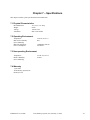
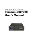
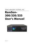
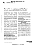
RAM-SANTM
User’s Guide
Any trademarks or registered trademarks used in this document belong to the companies that own them.
Copyright © 2003, Texas Memory Systems, Inc. All rights are reserved. No part of this work may be reproduced or used in
any form or by any means - graphic, electronic or mechanical, including photocopying, recording, taping, or information
storage and retrieval systems - without permission of the copyright owner.
Table of Contents
Chapter 1 - Overview .............................................................................................................................................................1-1
Chapter 2 - Installation ..........................................................................................................................................................2-1
2.1 Inspection .......................................................................................................................................................................2-1
2.2 E.S.D. Warning...............................................................................................................................................................2-1
2.3 Rack Mounting ...............................................................................................................................................................2-1
2.4 Connecting to the management port ...............................................................................................................................2-1
2.5 Power-Up........................................................................................................................................................................2-2
2.6 System Tests ...................................................................................................................................................................2-2
2.7 Connecting the Fibre Channel Ports ...............................................................................................................................2-2
Chapter 3 - Understanding Your RAM-SAN.......................................................................................................................3-1
3.1 Interface Slot Numbering ...............................................................................................................................................3-1
3.2 Inside the RAM-SAN .....................................................................................................................................................3-1
3.3 Bus Layout......................................................................................................................................................................3-1
3.4 Power..............................................................................................................................................................................3-1
3.5 Configuration Board and LEDs ......................................................................................................................................3-2
3.6 The Front Panel Display .................................................................................................................................................3-3
Chapter 4 – Configuring the RAM-SAN ..............................................................................................................................4-1
4.1 The RAM-SAN Monitor.................................................................................................................................................4-1
4.2 Configuring the Ethernet Port.........................................................................................................................................4-1
4.3 Configuring LUNS .........................................................................................................................................................4-1
4.3.1 A Worked Example on Changing the RAM-SAN Configuration............................................................................4-2
4.3.2 Resizing LUNs.........................................................................................................................................................4-3
4.3.3 Attaching Fibre Channel Ports to the LUNs ............................................................................................................4-3
4.3.4 Creating LUN Masks...............................................................................................................................................4-4
4.3.5 Saving the Configuration to Flash RAM .................................................................................................................4-5
Chapter 5 – Using the Management Port .............................................................................................................................5-1
5.1 testmem...........................................................................................................................................................................5-1
5.2 errchat <on/off>..............................................................................................................................................................5-1
5.3 exit (quit) ........................................................................................................................................................................5-1
5.4 help .................................................................................................................................................................................5-1
5.5 history .............................................................................................................................................................................5-2
5.6 ipconfig...........................................................................................................................................................................5-2
5.7 log ...................................................................................................................................................................................5-2
5.8 partition...........................................................................................................................................................................5-2
5.9 performance ....................................................................................................................................................................5-2
5.10 password .......................................................................................................................................................................5-2
5.11 reboot <hard/soft> ........................................................................................................................................................5-2
5.12 reset <port>...................................................................................................................................................................5-2
5.13 status [port] ...................................................................................................................................................................5-3
Chapter 6 - Troubleshooting..................................................................................................................................................6-4
6.1 Basic Items to Check ......................................................................................................................................................6-4
6.2 Management Port Fails to Boot ......................................................................................................................................6-4
6.2.1 MCP21 Does Not Display Characters .....................................................................................................................6-5
6.2.2 Boot Sequence Does Not Complete.........................................................................................................................6-5
6.2.3 Does Not Accept Character Input ............................................................................................................................6-5
6.3 RAM-SAN Boots Incorrectly .........................................................................................................................................6-5
6.3.1 RAM-SAN Detects Partial or No Memory..............................................................................................................6-5
6.3.2 RAM-SAN Does Not Detect all Devices.................................................................................................................6-6
6.3.3 Catastrophic Boot Error Detected............................................................................................................................6-6
6.4 Finding Bad Memory......................................................................................................................................................6-6
6.4.1 Locating a Bad Memory Board ...............................................................................................................................6-6
6.4.2 Confirming a Bad Memory Board ...........................................................................................................................6-6
6.5 Confidence Diagnostic, DIAGMEM, Fails ....................................................................................................................6-7
6.6 A Power Board LED Does not Light or Blinks or Bad Fuse LEDs are Lit ....................................................................6-7
6.7 Configuration LED Stays Lit..........................................................................................................................................6-7
6.8 ECC Errors Detected ......................................................................................................................................................6-8
RAM-SAN User’s Guide
Texas Memory Systems, Inc. (February 7, 2003)
i
6.9 How to Contact Us .........................................................................................................................................................6-8
Chapter 7 – Specifications......................................................................................................................................................7-9
7.1 Physical Characteristics ..................................................................................................................................................7-9
7.2 Operating Environment ..................................................................................................................................................7-9
7.3 Non-operating Environment ...........................................................................................................................................7-9
7.4 Warranty .........................................................................................................................................................................7-9
RAM-SAN User’s Guide
Texas Memory Systems, Inc. (February 7, 2003)
ii
Chapter 1 - Overview
The RAM-SANTM is a high-performance, multi-ported, solid-state disk. Memory capacity ranges from 16 gigabytes (GB)
through 128 GB in 16 GB increments1. Memory is organized internally in 128-bit wide words and accessed via four parallel
memory buses that can each sustain an aggregate bandwidth of up to 800 megabytes per second, giving a system bandwidth
of up to 3.2 GB per second.
The RAM-SAN features up to fifteen Fibre Channel I/O ports, each of which can sustain up to 200 megabytes per second in
full duplex mode. Multiple devices can access memory simultaneously at full speed, subject to the aggregate memory bus
bandwidth limit. The RAM-SAN also features a management port that is used for system diagnostics, configuration, and
monitoring.
The RAM-SAN 520 model also includes a hot swappable 2+1 redundant power configuration. Users should exercise caution
when changing out the power supplies.
1
One gigabyte is defined as 1,073,741,824 bytes.
RAM-SAN User’s Guide
Texas Memory Systems, Inc. (February 7, 2003)
1-1
Chapter 2 - Installation
The RAM-SAN is shipped with memory boards and interfaces already installed. Before connecting to a power supply, please
perform a preliminary inspection to check for any signs of loose parts, to ensure that all interfaces are still firmly positioned
in place, and to check for any obvious signs of damage. During power-up it is recommended that a terminal be attached to
the management port to observe its progress through the sequence of initial power-up tests. Once the system has completed
the power-up sequence, the management port should be used to execute a comprehensive system test prior to connection to
external devices, as detailed in section 2.6. See Chapter 4, Configuring the RAM-SAN, for more information on other
features of the management port.
2.1 Inspection
Inspect the rear of the chassis. Figure 1 shows the interface slot numbers for the RAM-SAN. Make sure that all of the
interfaces are securely installed in their slots, and that all screws are fully tightened.
Slot 2
Slot 6
Slot 10
Slot 14
Slot 1
Slot 5
Slot 9
Slot 13
Slot 0
Slot 4
Slot 8
Slot 12
PWR-25
2A Fuse Bad
7A Fuse Bad
DC ON
AC ON
PWR-25
2A Fuse Bad
7A Fuse Bad
DC ON
AC ON
I
O
Slot 15
I
Slot 11
O
Slot 7
I
O
Slot 3
PWR-25
2A Fuse Bad
7A Fuse Bad
DC ON
AC ON
Figure 1 – Rear view of RAM-SAN
2.2 E.S.D. Warning
IMPORTANT: please take full E.S.D. precautions if it is necessary at any time to come into contact with any circuit boards,
components or connectors. The components used in the RAM-SAN and its interfaces are easily damaged by electrostatic
discharge.
2.3 Rack Mounting
The RAM-SAN comes complete with rack slides for mounting in a standard 19” rack.
2.4 Connecting to the management port
The RAM-SAN is equipped with a management port that handles system initialization during power-up. The port can also be
used to execute system diagnostics, modify configuration, and monitor activity on the Fibre Channel ports. The management
port supports both Ethernet and serial connections.
RAM-SAN User’s Guide
Texas Memory Systems, Inc. (February 7, 2003)
2-1
The management port supports Ethernet connections via Telnet. The IP address may be assigned automatically using a
DHCP, BOOTP or RARP server. The IP address may also be statically set using the ‘ipconfig’ command from the serial
port.
The serial connection on the management port may optionally be used to communicate with the RAM-SAN. The cable
provided with the RAM-SAN connects to another serial port using the following settings:
8 data bits
No parity
1 stop bit
9600 baud
No flow control
2.5 Power-Up
The power cords are connected to the rear of the RAM-SAN chassis. The RAM-SAN is wired for 110/220 volt AC. A fully
loaded RAM-SAN will draw less than 525 Watts. Turn on all 3 power modules before switching on the master power
switch. This will ensure that none of the power modules are overloaded. You should see one neon bulb turn on as each
module’s power switch is activated. When the master power switch is turned on, a red LED should light up on each of the
three power supplies signaling OK DC power. On power-up, the system will boot up, run a few quick processor tests, and
initialize all of the internal memory. If you have a serial connection to the management port, you should see the following on
the display during power-up:
**
**
**
**
**
Starting
Creating
Creating
Creating
Creating
up TREX+ **
low-level tasks.......done
monitor task..........done
ethernet task.........done
DEVMAN tasks..........done
Texas Memory Systems, Inc.
RAM-SAN monitor
version x.xx
At this stage the RAM-SAN is ready for use.
2.6 System Tests
The management port is capable of running diagnostics on the internal memory of the RAM-SAN. This should be the first
test that is run after unpacking the system. By pressing enter, a prompt should appear on the serial connection. At this point,
type ‘testmem’. You may get a message that memory is still being initialized. If this happens, wait a few seconds before
trying this command again.
This diagnostics generates and checks data patterns in the memory system. If any error is found, a message describing the
error will be displayed. See Chapter 5 for a complete description of this command.
2.7 Connecting the Fibre Channel Ports
After checking the memory system, the Fibre Channel port may be connected to switches or other host bus adapters (HBAs).
The ports should automatically recognize another port is connected and be ready for use. See Appendix A for a device
compatibility listing. To verify a connection, use the ‘status’ command.
RAM-SAN User’s Guide
Texas Memory Systems, Inc. (February 7, 2003)
2-2
Chapter 3 - Understanding Your RAM-SAN
3.1 Interface Slot Numbering
Each device in a RAM-SAN has a unique internal address based on the physical location of the device in the system. An
interface’s port number can be determined by inspecting the back of the RAM-SAN (see Figure 1).
3.2 Inside the RAM-SAN
You can open the top of the RAM-SAN by removing the screws on the lid of the system. Standing at the back of the RAMSAN and looking down into the system the interfaces are closest to you, followed by the interface motherboard, and then the
memory slots. Please refer to the top-down view shown in Figure 3. As a reminder, please use caution if you open up the
RAM-SAN because the system is sensitive to static discharge. Additionally, it is best to keep the RAM-SAN lid on the
system while the power is on for airflow purposes.
3.3 Bus Layout
The RAM-SAN achieves its high memory bandwidth by multiplexing multiple busses into system memory – four in all. A
RAM-SAN bus is a direct connection to or from memory. Each bus supports up to 800MBytes per second. To maximize bus
bandwidth, several devices share bus connections, and each device is individually arbitrated for bus use.
Ports 0, 1, 2, and 3 are on bus A, ports 4, 5, 6, and 7 are on bus B, ports 8, 9, 10 and 11 are on bus C, and ports 12, 13, 14,
and 15 are on bus D. If only a few interfaces are present in the RAM-SAN, distributing them among all four buses and
putting each active DMA device alone on a bus can optimize performance. As you look at the rear of the RAM-SAN, an
ideal installation of four (4) Fibre Channel ports would be to use ports 3, 7, 11 and 15. Use this same approach as the number
of interface ports increase.
3.4 Power
The RAM-SAN is powered by three hot-swappable power supplies that deliver a 2+1 power redundancy. The system
requires that at least two of the modules be active while the system is turned on. There are LEDs on the power modules that
show the status of the AC, DC and the protective fuses (see Figure 2). The AC LED should light as soon as line power is
applied. The DC LED illuminates when you turn on the master power switch that is located in the lower left corner of the
RAM-SAN chassis. As a reminder, do not turn on master power switch unless at least two of the power cables are
connected.
O
I
PWR-25
2A Fuse Bad
7A Fuse Bad
DC ON
AC ON
Figure 2 – RAM-SAN Power Supply (PWR-25)
The following process should be followed when hot-swapping a power supply unit:
RAM-SAN User’s Guide
Texas Memory Systems, Inc. (February 7, 2003)
3-1
WARNING: Please exercise caution as you hot-swap power supplies for the RAM-SAN. Failure to follow these directions
could result in injury or death. If you have any questions about this procedure, call Texas Memory Systems at 713-266-3200.
1.
Turn off the power module that you plan to remove. Do not remove a hot swap power module from the chassis
without turning the power module off. The master power switch can remain “ON” as can the other power
modules.
2.
Wait 45 seconds and remove the power cord and power module.
3.
Reinsert the replacement module with the new module power “OFF”. The hot swappable power supplies use a
special blind mate connector to connect the RAM-SAN power motherboard. When the power board is inserted fully
into the system, the power supply faceplate should be flush with the surface of the chassis. Once properly seated
turn “ON” the new power module.
3.5 Configuration Board and LEDs
The system configuration board is a small circuit board that holds configuration information for the various programmable
components in the system. It plugs into a connector at the top of the interface motherboard (see Figure 3). The system
configuration board is upgradeable to support future hardware revisions. To upgrade, simply remove the old board by pulling
it towards the rear of the system and gently insert the replacement board.
There are two LED packages on the interface motherboard, one on either side of the system configuration board. Most of
these LEDs are dedicated to RAM-SAN diagnostics and activity monitoring, which are duplicated in detail by the front panel
display (see section 3.6). The three right-most LEDs in the package on the right side of the motherboard are the system
configuration LEDs. When the RAM-SAN is powered on, these three lights will turn on briefly, indicating that the
programmable components in the system are being configured. If any of the lights stay on after this, the RAM-SAN has not
configured correctly. If this happens, see section 6.7 in the troubleshooting section of this manual.
RAM-SAN User’s Guide
Texas Memory Systems, Inc. (February 7, 2003)
3-2
Figure 3 – Top-down View of RAM-SAN Internals
The Front Panel Display
Mounted on the front of the RAM-SAN is a front panel display (see Figure 4). When the RAM-SAN is in operation, the
display reflects the system memory activity. The display monitors three things: location of memory accesses, bus bandwidth
and which interface slots contain devices.
RAM-SAN User’s Guide
Texas Memory Systems, Inc. (February 7, 2003)
3-3
Figure 4 – RAM-SAN Front Panel
The RAM-SAN display consists of four rows of lights. Each row corresponds to one of the four RAM-SAN system busses.
The top row corresponds to interface ports 0, 1, 2 and 3, the next row to ports 4, 5, 6 and 7, the next row to ports 8, 9, 10 and
11, and the bottom row corresponds to interface ports 12, 13, 14, and 15. When any device on a bus is active, a light turns on
in the ADDRESSES section of the display corresponding to which gigabyte of memory it is accessing. Lights in the
BANDWIDTH section also turn on, showing the throughput of the bus in hundreds of megabytes per second.
The right-most section of the display shows which ports are loaded with devices. If a light is on, a device is present in that
slot.
RAM-SAN User’s Guide
Texas Memory Systems, Inc. (February 7, 2003)
3-4
RAM-SAN User’s Guide
Texas Memory Systems, Inc. (February 7, 2003)
3-1
Chapter 4 – Configuring the RAM-SAN
This chapter focuses on configuring the RAM-SAN. This includes configuring the Ethernet parameters, resizing LUNS, and
performing LUN Masking.
4.1 The RAM-SAN Monitor
The RAM-SAN is managed through an interactive command tool. The management software is accessed over Ethernet or
the serial port on the RAM-SAN. See section 2.4 for more information on connecting the hardware.
4.2 Configuring the Ethernet Port
The Ethernet port may be configured using automatic IP address assigned via bootp or rarp. Consult with your system
administrator for the proper procedure in this type of network configuration.
The following procedure may be used to statically set the IP from the serial port:
1.
2.
3.
4.
Using the serial cable provided connect the management port to a serial port on a computer or dumb terminal.
The serial settings should be 9600 baud, 8 data bits, no parity, and 1 stop bit.
Make sure the power cable is connected to the RAM-SAN and turn it on.
You should see messages on the console that show the power-on stages.
Once you see the ‘ram-san>’ prompt, enter the ‘ipconfig’ command. If you are using an automated IP
assignment such as reverse address resolution protocol (rarp) then select 2. Otherwise the static IP selection
will prompt you for your IP, subnet mask, and gateway. Pressing return without any input will automatically
pick the default value. The output from the ‘ipconfig’ command looks like this:
ram-san> ipconfig
1. Static IP
2. Rarp or Bootp
Select: 1
Ethernet IP address [255.255.255.255]: 192.94.231.201
Ethernet subnet mak [255.255.255.0]: <enter>
Ethernet gateway [255.255.255.255]: <enter>
ram-san>
5.
NOTE: Type ‘reboot soft’ to reboot the RAM-SAN in order for the changes to take effect.
4.3 Configuring LUNS
The RAM-SAN is extremely versatile because it supports a variety of configurations and access control methods. The
factory default configuration assumes no LUN masking and equal LUN sizes for each Fibre Channel port. For example, if
you have an 8 GB system with 2 Fibre Channel ports, each port will only have access to one 4 GB LUN. Any host computer
attached to the same Fabric as the RAM-SAN will see two 4 GB drives.
RAM-SAN
8 Gigabytes
System
Memory
Fibre Channel
ports
RAM-SAN User’s Guide
4 Gigabyte drive
4 Gigabyte drive
FC21
FC21
Texas Memory Systems, Inc. (February 7, 2003)
4-1
The amount of storage allocated to each Fibre Channel port may be changed using a simple configuration utility provided in
the monitor. To enter this utility, type ‘partition’ on the monitor command line. You should see a message similar to this
one:
ram-san>
ram-san> partition
** RAM-SAN partitioning utility **
Total memory size: 8192 Mb
Command (h for help):
To see a list of the available commands, type ‘h’ at the prompt.
Command (h for help): h
a add wwn to LUN Mask
d delete wwn from LUN Mask
l link an fc port to LUN
p print the LUN table
q quit without saving changes
r resize LUNs
u unlink an fc port from LUN
w write changes to flash and exit
Command (h for help):
Using the ‘p’ command, you can view partition information for either a single port or the entire RAM-SAN. The following is
the LUN table for the example RAM-SAN hardware configuration shown above.
Command (h for help): p
Enter the LUN number (1-2, default is all): <enter>
LUN 1 -- 4096 Mb
ports: 5
access: Open access
LUN 2 -- 4096 Mb
ports: 9
access: Open access
Command (h for help):
4.3.1 A Worked Example on Changing the RAM-SAN Configuration
The following sections detail how to change size of the LUNs within the system. We will change the factory configuration
that is explained above. The new configuration will consist of three LUNs and have LUN masks that allow only four host
machines to access the RAM-SAN.
For the sake of discussion, we will assume we have four HBAs connected to the same fabric that the RAM-SAN’s Fibre
Channel ports are attached.
The new configuration will consist of three LUNs that are accessed using two Fibre Channel ports in the RAM-SAN. HBA 1
and HBA 2 will each be assigned a unique LUN, while HBA 3 and HBA 4 will share the same LUN.
The goal of the example is to create the following configuration:
RAM-SAN User’s Guide
Texas Memory Systems, Inc. (February 7, 2003)
4-2
RAM-SAN
8 Gigabytes
System
Memory
3 Gigabyte drive
1
Fibre Channel
ports
HBA 1
3 Gigabyte drive
2 Gigabyte
drive
2
FC21
HBA 2
3&4
FC21
HBA 3
HBA 4
4.3.2 Resizing LUNs
The first step in changing the configuration is to resize the LUNs. Since our new configuration calls for three different
LUNs, we need to use the ‘r’ command to resize LUNs. This command allows us to keep or delete the previous LUN mask
and port assignments. This is useful if the only change is in the size of the LUNs. In this case, we want to delete any
previous port and LUN masks that had been made. The following show the procedure for creating the three LUNs for our
example.
Command (h for help): r
How many LUNs would you like to make? 3
Would you like to remove port assignments (Y/n)? <enter>
Would you like to remove LUN masks (Y/n)? <enter>
LUN 0 size (default 8192 Mb): 3072
LUN 1 size (default 5120 Mb): 3072
LUN 2 size (default 2048 Mb): <enter>
Command (h for help): p
Enter the LUN number (1-3, default is all): <enter>
LUN 1 -- 3072 Mb
ports:
access: Open access
LUN 2 -- 3072 Mb
ports:
access: Open access
LUN 3 -- 2048 Mb
ports:
access: Open access
Command (h for help):
At this point, we have divided the system memory into three LUNs. Next we need to assign ports to each LUN.
4.3.3 Attaching Fibre Channel Ports to the LUNs
Now that we have created our LUNs, we need to assign the Fibre Channel ports to them. This is accomplished with the
‘l’(ell) command. We simply link a particular LUN to a port number. The follow example shows how this is done.
Command (h for help): l
RAM-SAN User’s Guide
Texas Memory Systems, Inc. (February 7, 2003)
4-3
Enter the LUN number: 1
Enter the Fibre Channel port: 5
Command (h for help): l
Enter the LUN number: 2
Enter the Fibre Channel port: 5
Command (h for help): l
Enter the LUN number: 3
Enter the Fibre Channel port: 9
Command (h for help): p
Enter the LUN number (1-3, default is all): <enter>
LUN 1 -- 3072 Mb
ports: 5
access: Open access
LUN 2 -- 3072 Mb
ports: 5
access: Open access
LUN 3 -- 2048 Mb
ports: 9
access: Open access
Command (h for help):
From the last command, we can see that the port five has been assigned to LUN one and three, and port nine has been
assigned to LUN two and three. Since we are sharing a port between two LUNs, we need to specify a LUN mask so that the
HBA will only be able to access the desired LUN.
4.3.4 Creating LUN Masks
The next configuration option available to the RAM-SAN is the ability to create LUN Masks for individual Fibre Channel
ports. This allows the administrator to specify which HBAs are allowed to communicate with each LUN. The ‘a’ command
will add a world wide name to a LUN’s access list, activating the masking of that LUN to all other HBAs. The following
command sequence will add all four world wide names to our LUN mask.
Command (h for help): a
Enter LUN number: 1
Enter the world wide name (colon delineated): 11:11:11:11:11:11:11:11
Command (h for help): a
Enter the LUN number: 2
Enter the world wide name (colon delineated): 22:22:22:22:22:22:22:22
Command (h for help): a
Enter the LUN number: 3
Enter the world wide name (colon delineated): 33:33:33:33:33:33:33:33
Command (h for help): a
Enter the LUN number: 3
Enter the world wide name (colon delineated): 44:44:44:44:44:44:44:44
Command (h for help): p
Enter the LUN number (1-3, default is all): <enter>
LUN 1 -- 3072 Mb
ports: 5
access: 11:11:11:11:11:11:11:11
LUN 2 -- 3072 Mb
ports: 5
access: 22:22:22:22:22:22:22:22
LUN 3 -- 2048 Mb
ports: 9
access: 33:33:33:33:33:33:33:33
44:44:44:44:44:44:44:44
Command (h for help):
RAM-SAN User’s Guide
Texas Memory Systems, Inc. (February 7, 2003)
4-4
4.3.5 Saving the Configuration to Flash RAM
The RAM-SAN has now been configured to allow access from four different HBAs to 3 different LUNs within the memory
system. To actually commit the change we have made, we can use the ‘w’ command to save the configuration into Flash
RAM. You may also use the ‘q’ command to quit the partitioning utility without saving any changes.
RAM-SAN User’s Guide
Texas Memory Systems, Inc. (February 7, 2003)
4-5
Chapter 5 – Using the Management Port
The management port on the RAM-SAN allows an administrator to configure the system, monitor performance, and diagnose
problems with the system. The ‘help’ command displays a list of commands available. The following sections provide a
more detailed description of the commands available through the monitor.
5.1 testmem
The ‘testmem’ command is used to verify the integrity of the system memory. This command causes the management port to
generate and check patterns in the shared memory area. Any errors that are found are reported to the monitor along with the
address in memory and the data that failed. WARNING: This test should only be run when there are no attached Fibre
Channel connections because all data in system memory is overwritten by this test. The monitor also displays a line that
shows the parameters associated with each test. The following is output from the ‘testmem’ command:
ram-san> testmem
All data in the RAM-SAN will be destroyed.
Continue (yes/no)? yes
Press ‘Q’ to Quit
004729 sa:0x00e8f458 wc: 0x014a5390 64-bit COMPLX RND
The first number denotes the test iteration. The next two numbers are the starting address and word count for the test. The
last part of the line describes the type of pattern being tested. In this case a complex 64-bit random pattern is used. This test
is used to find bit error and ECC errors in system memory. Data errors will be shown as part of the ‘testmem’ command.
ECC errors may be viewed using the ‘log’ command from the command line. Any ECC errors will be noted with a terminal
beep and a message.
NOTE: THIS COMMAND DESTROYS ALL DATA IN SYSTEM MEMORY.
5.2 errchat <on/off>
The ‘errchat’ command toggles the displaying of ECC error messages. All errors are still logged to on the management port,
but the error warning is not displayed. This function is useful for systems that find an error but still need to be used without
the constant reporting of the error.
5.3 exit (quit)
The exit command is used to close a telnet connection. This command has no effect from the console.
5.4 help
The help command provides a brief online description of each command that is available. Commands that require parameters
are listed with the ‘<parameters>’ as options.
ram-san> help
testmem
errchat
exit
help
history
ipconfig
log
partition
password
performance
reboot <hard/soft>
reset <port>
status
RAM-SAN User’s Guide
:
:
:
:
:
:
:
:
:
:
:
:
:
Run memory diagnostics (destructive)
Togles ECC error chattering on or off
Logout of the monitor
List a table of commands
Show command line history
Configure ethernet parameters
Displays a list of system ecc errors
Disk space allocation utility
Sets the login password
Displays system performance
Power on reset of the RAM-SAN
Resets a Fibre Channel port
Prints status information
Texas Memory Systems, Inc. (February 7, 2003)
5-1
5.5 history
The monitor maintains a volatile command history of the last 25 commands that have been entered. Using the ‘history’
command provides a listing of the history. Commands may be entered using the ‘<’ and ‘>’ keys to scroll through this
history or the unix-like ‘!’ commands. The command history is volatile and will not be maintained between power cycles.
5.6 ipconfig
The ‘ipconfig’ command allows for static IP configuration of the RAM-SAN. More information on this command may be
found in section 4.2. Note that setting an entry to 255.255.255.255 will cause rarp or bootp to be used.
5.7 log
The ‘log’ command may be used to obtain more information on the ECC error that occurred. See section 6.4 for more
information on diagnosing problems with system memory.
5.8 partition
The ‘partition’ command is a memory-partitioning tool that allows the administrator to configure system memory into subsections (LUNs) that may be accessed by specific Fibre Channel ports in the RAM-SAN. The sections may also be assigned
access lists (LUN masks) that limit the visibility of the RAM-SAN to specific servers. See section 4.3 for more details on
partitioning the RAM-SAN.
5.9 performance
The ‘performance’ command may be used to view the bandwidth of the system back plane for each port. The monitor shows
the average bandwidth of each port over a period of one second. This performance view shows only DMA activity and does
not show other Fibre Channel activity. To stop the output from this command, press any key.
5.10 password
Since it is possible to access the RAM-SAN remotely through the management port, a password feature has been included for
system security. By default, this password is not set, and thus not requested when connecting to the system. If a password is
created, then all logins to the RAM-SAN will require this password. In order to change the password, the current password
must be entered first. However, on the console, the password may be set without requiring the current password.
The password feature may be bypassed on the console by simply pressing <enter> when prompted for the password. This
feature allows a system administrator access to the RAM-SAN if the password is forgotten.
5.11 reboot <hard/soft>
The reboot command has two forms. The first type is a soft reboot. The command is invoked with ‘reboot soft’. Using this
command will reset the management port and disconnect from all telnet sessions. Note that this type of reboot does not
destroy any data in system memory, so soft reboots are non-destructive to the RAM-SAN.
The other type of reboot command is ‘reboot hard’. This command will perform a power-on reset of the system. As a result,
all data stored in system memory will be destroyed. This command should only be used if all attached machines have
disconnected their drives from the RAM-SAN. As an added safety precaution, this command requires the administrator to reenter the password before rebooting.
5.12 reset <port>
The ‘reset’ command allows the administrator to reset individual ports on the RAM-SAN. This command should only be
needed under rare circumstances since the Fibre Channel ports handle the appropriate reset protocol. To issue this command,
a port number is specified as a parameter to the command.
RAM-SAN User’s Guide
Texas Memory Systems, Inc. (February 7, 2003)
5-2
5.13 status [port]
The status command provides an overview of the RAM-SAN including Ethernet information, memory size, and the state of
the Fibre Channel ports. The following output shows a sample status screen:
ram-san> status
Texas Memory Systems, Inc.
RAM-SAN Monitor
version 1.00
Ethernet address: 00:20:c2:00:07:f1
Ethernet IP:
192.94.231.201
Total memory size: 8192 MB - Ready
port 1: --port 2: offline
port 3: --port 4: --port 5: 10:05:00:20:c2:00:07:f1
port 6: --port 7: --port 8: --port 9: no light
port 10: --port 11: --port 12: online
no login
port 13: --port 14: 10:05:00:20:c2:00:07:f1
port 15: --ram-san>
online
F-port
online
N-port
The first few lines display the current firmware revision for the management port and the Ethernet settings associated with
this RAM-SAN. The following lines show the location of the Fibre Channel ports. There are five Fibre Channels in this
RAM-SAN located in ports 2, 5, 9, 12, and 14. You can also see that this is an eight-gigabyte system. Following the
memory size is either the word “Initializing” or “Ready”. The box must check and initializing the system memory during
power-up. Therefore, all Fibre Channel port are left offline and the word “Initializing” is displayed. Once the memory
initialization is complete, the word “Ready” is displayed, and the RAM-SAN is ready for use.
Each port has a line that describes the current state of the Fibre Channel port. The string ‘---‘ means that no Fibre Channel
port exists in that location. The first column describes the line state of the port. A ‘no light’ string means that a signal is not
being detected by the receiver. ‘Offline’ means that a signal has been detected but the low level link-up has not been made.
An ‘online’ port is one that has recognized another Fibre Channel device on the other end of the connection. The second
column describes the type of RAM-SAN connection port. ‘No login’ means that a link has been established but the other
type of port is not yet known. An ‘F-port’ means that the RAM-SAN is connected to a fabric on that particular port, while an
‘N-port’ means a point-to-point connection with an HBA has been made. The last column is the port name (world-wide
name) for the port directly connected to the RAM-SAN.
The status command may also take a port number for a parameter. Entering this parameter results in a display for an
individual port. All of the above information is displayed for the port along with other descriptive data such as the world
wide name of the port connected to the RAM-SAN.
RAM-SAN User’s Guide
Texas Memory Systems, Inc. (February 7, 2003)
5-3
Chapter 6 - Troubleshooting
This chapter is a quick troubleshooting guide for the most common RAM-SAN errors. To verify basic RAM-SAN operation,
please consult Chapter 5 for instructions on running the system diagnostics. Below is a short list of RAM-SAN errors,
symptoms and solutions. If this guide does not identify and correct your problem, please call Texas Memory Systems
customer support at (713) 266-3200.
6.1 Basic Items to Check
When touching any of the internal components, remember to use a grounding strap attached to the RAM-SAN chassis - the
chassis is connected to earth ground from the power connector. Take care around the power modules, as they are dangerous
and can hold a charge for minutes after being powered off. Do not touch the power board unless the RAM-SAN is
disconnected from the power outlet and has been disconnected for more than a minute. Make sure the RAM-SAN power is
off before removing or adding any memory boards or interfaces. If you are uncomfortable with any of these instructions,
please feel free to call Texas Memory Systems customer support instead. See Figure 3 for a depiction of the RAM-SAN
internals. The following are some general items to check if you are having problems with your system:
•
•
•
•
Make sure that the RAM-SAN internal fans are blowing when your system is powered on. This proves that the
RAM-SAN has power.
When turning on your RAM-SAN, please be sure that the power was off for at least 30 seconds. The internal power
supplies take some time to dissipate their charge. Several of the parts in the system require a full power down to
properly reset. The best way to guarantee that the power supply is off is to wait until the internal RAM-SAN fans
come to a complete stop.
Reset your serial device. Some serial devices need to synchronize their ports with the attached device.
Check that the system configuration board is properly seated in its connector at the top of the interface motherboard.
If it has come loose or doesn’t look fully seated, push the board gently back into place. Make sure it is aligned in its
slide rails before pushing the connectors together.
6.2 Management Port Fails to Boot
When the management port fails to boot, three things can happen:
•
•
•
The MCP21 displays nothing on the dumb terminal and accepts no input from the keyboard.
The MCP21 boot-up sequence does not complete and freezes somewhere in the middle of the sequence described in
section 3.5.
The MCP21 boots to completion but sometime afterwards the MCP21 hangs and does not accept character input.
RAM-SAN User’s Guide
Texas Memory Systems, Inc. (February 7, 2003)
6-4
6.2.1 MCP21 Does Not Display Characters
If nothing is displayed on the dumb terminal connected to the RAM-SAN, try the following:
• Check for solid serial cable connection at both the management and the debug monitor.
• Be sure that the dumb terminal is set at 9600 baud, no parity, eight data bits, one stop bit, no flow control and US/CR
terminator.
• Try adding a null modem adapter to the serial connection.
6.2.2 Boot Sequence Does Not Complete
If the RAM-SAN hangs in the middle of its boot sequence, try the following:
•
Verify that there is no RAM-SAN activity by viewing the bandwidth section of the front panel display (see section 3.6).
If there is activity, wait for it to complete.
6.2.3 Does Not Accept Character Input
If the RAM-SAN has booted successfully, but will not accept dumb terminal I/O, be sure that the ram-san> prompt is visible
and you should be able to type on the console. If character I/O does not work, try the following:
•
•
Check for solid serial cable connection at both the RAM-SAN and at the dumb terminal.
Make sure that the terminal is set at 9600 baud, no parity, eight data bits, one stop bit, no flow control and US/CR
terminator.
6.3 RAM-SAN Boots Incorrectly
During the power-up sequence of the RAM-SAN, the management port initializes and queries the system for configuration
information. During this time, minor internal diagnostics are run in the system. Most errors at this time will be one of three
things: the RAM-SAN detects no or partial memory; the RAM-SAN detects no or a few of the Fibre Channel ports; the
power-up sequence is interrupted by a catastrophic error such as a reset, internal trap, or SAMnet error.
6.3.1 RAM-SAN Detects Partial or No Memory
If the MCP21 reports on the boot screen that partial or no memory was detected, please do the following. Always use a
grounding strap and be careful around the power board – it is dangerous. Also, always turn off the power before moving any
boards in the system.
•
•
•
•
•
•
If there is an interface in slot 8, remove it or move it to another slot. If there is a blank faceplate in slot 8, remove it.
Open the top lid of the RAM-SAN and then turn on the power.
Verify that all power modules have both the AC and DC LEDs on and the bad fuse LEDs off.
After all system activity has stopped and you see the VIM+ prompt displayed on the dumb terminal, verify that
none of the configuration LEDs are lit. These are the three right-most LEDs on the interface
motherboard. (See section 3.5) If any are lit, please consult section 6.7 for more information.
Verify that your memory boards are in the correct memory slots. If you have two memory boards, they
should be in slots 0 and 4. If you have four memory boards, they should be in slots 0,1,4 and 5. If you
have six, they should be in slots 0,1,2,4,5 and 6. You must always have an even number of memory
boards in the system. See Figure 3 for a depiction of the RAM-SAN memory slots.
Turn off the power and verify that all memory boards are tightly seated in the memory system. To do
this, press firmly on the memory board handles visible from the top of the system. The handles will
distribute pressure evenly on the memory board.
Turn off the power and reseat the memory boards by lifting the handles from the memory board. Be
sure to wear a grounding strap attached to the RAM-SAN chassis – the RAM-SAN memory boards are
one of the most expensive parts of the system. The handles are designed to use the metal card cage as a
fulcrum to gently leverage out the memory boards. Once the memory board is removed, check its
connector for stress or damage. Use a flashlight to check the RAM-SAN memory board connectors for
damage. Seat the memory board back into the system by slowly sliding the memory board into the
memory slot using the card rails as a guide. Make sure the memory board handles are up so that they
hook underneath the card cage. Try to visually verify that the memory board has correctly seated into
RAM-SAN User’s Guide
Texas Memory Systems, Inc. (February 7, 2003)
6-5
•
the memory connector – the connector has a key to keep the memory board from going in backwards or
awkwardly. Once in place, use the handles to evenly leverage the memory board into the slot.
If none of the above hints helped, faulty hardware may exist. Follow the steps in section 6.4, Finding
Bad Memory, and try to pinpoint which memory board has a problem. Then contact Texas Memory
Systems customer support at (713)266-3200.
6.3.2 RAM-SAN Does Not Detect all Devices
When the boot sequence completes, all devices should be accounted for both in the READY lights on the front
panel display and on the status screen printed to the dumb terminal by the management port. If any devices
are missing, try the following. Please use a grounding strap and be careful around the power board – it is
dangerous.
•
•
•
Verify that the system powered-up correctly by turning off the power for more than 30 seconds and then
turning it back on.
Verify that all power modules have both the AC and DC LEDs on and the bad fuse LEDs off.
If an interface is missing from the display, reseat the interface in the RAM-SAN. First, unscrew the
faceplate from the RAM-SAN. There are four screws that connect it to the chassis – one in each corner of
the front plate. Always turn off the power to the RAM-SAN before removing any boards from the
system. Pull the interface from the system using the handles. Examine the interface connector for
stress and wear. Examine the interface and check for loose components, particularly any socketed parts.
Use a flashlight to examine the interface port for stress and bent pins. Gently but firmly seat the
interface into its port using the slide rails as guides and tighten the faceplate screws.
6.3.3 Catastrophic Boot Error Detected
Call Texas Memory Systems for help diagnosing the problem.
6.4 Finding Bad Memory
This step-by-step guide will help you locate and confirm a faulty memory board or chip in your RAM-SAN. If
only a handful of bit errors are present, the problem may be with a single memory chip, which can be located
using this guide. If larger sections of the data word are affected, a more general board problem may exist.
See section 6 above for an example of where to look in the error message to see how many bits are at fault.
Please try to pinpoint the bad board and, if possible, chip, and then contact Texas Memory Systems customer
support.
6.4.1 Locating a Bad Memory Board
Bad memory will be reported by the system through an ECC error message. When data is read from
memory and the ECC value is incorrect, the device reports an ECC message to the management port. If the
error is a single bit error, the ECC logic corrects the data bit. Multiple bit errors are not correctable by the
ECC mechanism. Use the ‘log’ command to display the following screen is an example of an ECC error log
report.
ram-san> log
Source: 0x0000, ECC word: 0x25, Burst addr: 0x0082000100, Error word cnt: 0x14
An error was detected on bit 9.
Bus: 2 Board: 4 Bank: 1
6.4.2 Confirming a Bad Memory Board
Once you have isolated the board and, if possible, the chip associated with an error, it is wise to double-check
that the problem is truly with the memory board, and not the system slot where the board resides. To test
this, turn off the power to the system, wait for the fans to stop, and swap the board in question with one of
the working memory boards. (Make sure to use a grounding strap when removing boards from the system.)
RAM-SAN User’s Guide
Texas Memory Systems, Inc. (February 7, 2003)
6-6
Then repeat the steps above to confirm that the memory error followed the suspected board to the new board
slot.
Contact Texas Memory Systems with all the information you have found to begin actions to resolve the
problem.
6.5 Confidence Diagnostic, DIAGMEM, Fails
If the ‘testmem’ test produces error messages, use section 6.4 above to narrow down the problem to a specific
memory board and, if possible, chip. If you call Texas Memory Systems customer support, be sure to log the
information so the support technicians can use it to determine what part of your RAM-SAN is
malfunctioning. If you trace the problem to a specific memory board, try to reseat the board by following the
instructions in section 6.3.1.
6.6 A Power Board LED Does not Light or Blinks or Bad Fuse LEDs are Lit
When a Hot-Swappable power supply is functioning correctly, two LEDs will be lit: AC ON and DC ON.
The LEDs are on the faceplate of the power supply module (see Figure 2), and can be seen on the rear of the
chassis.
If the DC ON and the AC ON LEDs are off or blinking, try the following:
WARNING: Please exercise caution as you hot-swap power supplies for the RAM-SAN. Failure to follow these directions
could result in injury or death. If you have any questions about this procedure, call Texas Memory Systems at 713-266-3200.
•
•
•
•
This is just a reminder to be sure not to touch the power board components while the power supply is
plugged in and turned on. Wait for at least one minute after power-down – the power supply can
hold a dangerous charge.
Make sure that all RAM-SAN internal fans are operational and have unblocked airflow. The RAM-SAN
power supply will go into thermal shutdown if it is not properly cooled. This will cause the power LED to
blink as it turns itself on and off depending upon the internal temperature. If a bad fuse LED is lit,
contact a Texas Memory Systems customer support technician for instructions on how to replace the
fuse.
If more than one of the power supplies have blinking lights and the fans are not running, then check the
2A Fuse Bad LED on the power supply nearest the fans. If it is also lit, then it is possible that the fans
are not receiving power. Remove that power supply and contact Texas Memory Systems customer
support (713-266-3200) for help replacing the fuse. Once the power supply is removed from the system,
another power supply will take its place powering the fans.
If the DC ON LED is not lit up, turn the power supply’s AC switch off, and leave it off for 2 minutes. A
power glitch might have locked up the load sharing control and turned off the converter. The converter
must discharge its internal capacitance before it will function correctly. After 2 minutes, turn the AC
power switch back on and see if the DC OK LED lights up. If the LED does not light up, or this problem
occurs frequently, contact Texas Memory Systems customer support to remedy the problem.
Verify that the power board is properly connected to the RAM-SAN system motherboard. The hot swappable
power supplies use a special blind mate connector to connect the RAM-SAN power motherboard. When the
power board is inserted fully into the system, the power supply faceplate should be flush with the surface of
the chassis.
6.7 Configuration LED Stays Lit
Be sure all system activity is stopped before checking if the configuration LEDs are lit. The configuration
LEDs share LED packages with system activity LEDs. If the system is not idle, chances are, some of the
LEDs in the RAM-SAN will be lit. Configuration LEDs should only be lit upon power-up and will remain lit
for only a second. Several things can cause a configuration LED to stay lit: heat, power surges, bad power,
RAM-SAN User’s Guide
Texas Memory Systems, Inc. (February 7, 2003)
6-7
power glitches or a serious hardware failure. If a configuration LED stays lit after power-up, do the
following:
•
•
•
•
Verify that the oscillator is firmly inserted into its slot. The oscillator is located in the center of the
system motherboard, between the connectors for memory slot 5. The writing on the oscillator should be
oriented in the same direction as the text next to it on the motherboard that reads “50MHz” and “3.3V”.
Check that the system configuration board is properly seated in its connector at the top of the interface
motherboard. If it has come loose or doesn’t look fully seated, push the board gently back into place.
Make sure it is aligned in its slide rails before pushing the connectors together.
Make sure that all RAM-SAN internal fans are operational and have unblocked airflow. The RAM-SAN
power supply will go into thermal shutdown if it is not properly cooled. This will cause the power LEDs
to blink as they turns themselves on and off depending upon the internal temperature. If one of the
RAM-SAN power modules turns off, parts of the system will be unable to reconfigure themselves and
will leave the configuration LED on.
If you suspect that the RAM-SAN has experienced a power surge or glitch, turn off the RAM-SAN, wait
for the internal fans to stop and then turn the system back on.
6.8 ECC Errors Detected
The RAM-SAN hardware has a mechanism for detecting system data errors using an error correction code
(ECC). ECC errors are caused by bits being read from system memory incorrectly and are reported to the
management port. If an ECC error is detected the management port reports:
** ECC error detected
Please follow the steps in section 6.4 to pinpoint the erroneous memory board and/or chip and call Texas
Memory Systems customer support. You will need to be at the RAM-SAN monitor while talking to a
customer support technician, with an error logged on the management port (resetting or turning off the
RAM-SAN will cause the management port to lose the ECC error log).
6.9 How to Contact Us
At Texas Memory Systems, Inc. we strive to meet our customers’ needs by providing quality products and
documentation. This Users Guide will answer many of your initial questions. Please feel free to contact our
Customer Support Department with any additional questions, concerns, or comments regarding your
system.
Texas Memory Systems, Inc.
11200 Westheimer Road, Suite 1000
Houston, TX 77042
www.texmemsys.com
Tel: (713) 266-3200, Fax (713) 266-0332
RAM-SAN User’s Guide
Texas Memory Systems, Inc. (February 7, 2003)
6-8
Chapter 7 – Specifications
This chapter contains system specifications for the RAM-SAN.
7.1 Physical Characteristics
Rack Mount Size:
Weight:
Voltage:
Ventilation:
7U (12.2”) x 25” deep
90 lbs.
110/220 VAC
Side to side airflow
7.2 Operating Environment
32-85 °F (0-30 °C)
80%
Temperature:
Max relative humidity:
(non-condensing)
Max heat dissipation:
Power consumption:
1700 Btu/hr (500 W)
100-550 W
7.3 Non-operating Environment
Temperature:
Relative Humidity:
(non-condensing)
32-150 °F (0-65 °C)
10-90%
7.4 Warranty
1 year FOB
Texas Memory Systems, Inc.
Houston, Texas
RAM-SAN User’s Guide
Texas Memory Systems, Inc. (February 7, 2003)
7-9
RAM-SAN User’s Guide
Texas Memory Systems, Inc. (February 7, 2003)
i