1
(#)*"*&'-.
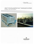
TI4100 GPU-24
!"#$%&'(#)*"'$%+,
!"#$%& '()*#+,-"#& '(./
012&3"(+",45-(+&6$7)/
8"9&3%#+$":&;<&02=>1
?@1>A@>BCD201&4E5("
?@1>A&@>BCD20>&F%G
www.TESLAind.com
WARNING
*******SHOCK HAZARD POTENTIAL*******
IMPROPER USE/FAILURE TO FOLLOW INSTRUCTIONS IN OPERATORS MANUAL CAN RESULT IN UNIT FAILURE AND/OR POSSIBLE INJURY, OR DEATH, BY ELECTRICAL
SHOCK.
THE TI4100GPU-24 IS A MAINTENANCE FREE, SEALED UNIT
NO REPAIRS ARE AUTHORIZED.
WARRANTY WILL BE VOID IF
UNIT IS TAMPERED WITH.
FOR TECHNICAL SUPPORT CONTACT:
TESLA INDUSTRIES INC.
109 CENTERPOINT BLVD.
CENTERPOINT INDUSTRIAL PARK
NEW CASTLE, DELAWARE 19720
PH.(302)324-8910
FAX (302)324-8912
WARNING
*******SHOCK HAZARD POTENTIAL*******
ATTEMPTS TO OPEN OR ENTER THE INSIDE OF THIS UNIT (BY USING ANY TOOL
OR DEVICE; i.e. PROBE, BORESCOPE, etc.) CAN RESULT IN UNIT FAILURE
AND/OR POSSIBLE INJURY BY ELECTRICAL SHOCK.
THIS UNIT IS MAINTENANCE
FREE AND SHALL NOT BE OPENED OR DISASSEMBLED FOR ANY REASON.
***SHIPPING HAZARDS***
“NONE”
“DRY” Non-spillable, POWER CELL (battery),
No Free liquids,
to leak or toxic gases.
Always protect unit from short circuit.
Return Power cells to Tesla for Recycling.
i
TABLE OF CONTENTS
TITLE
Page
CHAPTER 1
INTRODUCTION
1-1
CHAPTER 2
UNIT DESCRIPTION AND OPERATION
2-1
Section I
Unit
2-1
Section II
Description
2-2
CHAPTER 3
OPERATING LIMITS AND RESTRICTIONS
3-1
Section I
General
3-1
Section II
Operational Restrictions and Safety Limits
3-1
CHAPTER 4
OPERATING PROCEDURES
4-1
Section I
Unit Operation
4-1
Section II
Operating Procedures
4-2
Section III
Functional Check Procedures
4-5
CHAPTER 5
PERFORMANCE DATA
5-1
Section I
Introduction
5-1
Section II
Data Criteria
5-2
CHAPTER 6
CARE AND MAINTENANCE
6-1
Section I
Unit Care
6-1
Section II
Maintenance
6-2
CHAPTER 7
Push to Test
7-1
Section I
General
7-1
Section II
Operation
7-1
CHAPTER 8
On/Off Switch
8-1
Section I
General
8-1
Section II
Operation
8-1
INDEX
Index 1
LIST OF ILLUSTRATIONS
Figure
Title
Page
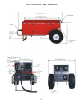
2-1
Dimensions
2-3
2-2
General Details
2-4
5-1
Temperature Conversion Chart
5-3
5-2
Discharge Load Curve
5-4
5-3
Maximum Output Current
5-5
ii
CHAPTER 1
INTRODUCTION
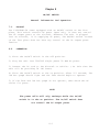
1-1.
GENERAL
These instructions are for use by the owner/operator.
They apply to
handling and operation of the TI4100GPU-24 (Turbo Start 4100) ground
power unit.
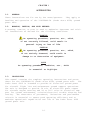
1-2.
WARNING, CAUTION, AND NOTE DEFINED
A warning, caution, or note is used to emphasize important and critical instructions as defined for the following conditions:
WARNING
An operating procedure, practice, etc., which,
if not correctly followed, could result in
personal injury or loss of life.
CAUTION
An operating procedure, practice, etc., which,
if not strictly observed, could result in
damage to or destruction of equipment.
NOTE
An operating procedure, condition, etc., which
is essential to highlight.
1-3.
DESCRIPTION
This manual contains the complete operating instructions and procedures for the TI4100GPU-24 (Turbo Start 4100) ground power unit.
The
Turbo Start 4100 is intended to provide DC electrical ground power
for aircraft flight line and maintenance ground support operations.
The unit is designed to provide 24 volt DC electrical power output
for aircraft engine starting and 24 or 28.5 volts DC electrical support for ground maintenance, avionics/electrical trouble shooting and
testing.
The observance of procedures, limitations and performance
criteria is essential to ensure peak operating efficiency and to
maximize operational capabilities and life of the Turbo Start 4100
ground power unit.
1-1
1-4.
INDEX
The index lists, in alphabetical order, every titled paragraph and
figure contained in this manual.
1-5.
ABBREVIATIONS AND SYMBOLS
Abbreviations and symbols are used within text, headings and titles.
Unless otherwise indicated, the following list of abbreviations and
symbols are used in this manual:
LIST OF ABBREVIATIONS AND SYMBOLS
Abbreviation
Definition
amp
Ampere
AC
Alternating Current
C
Celsius
cont
Continuous
DC
Direct Current
F
Fahrenheit
Ft
Feet
FWD
Forward
GPU
Ground Power Unit
Hr
Hour
Hz
Hertz
Kg
Kilograms
Kw
Kilowatts
°
Degree
LED
Light Emitting Diode
MAX
Maximum
MIN
Minimum
VAC
Volts, Alternating Current
VDC
Volts, Direct Current
Explosion Hazard Potential
Shock Hazard Potential
Guard from moisture
㺪 㺸㺤㺵 㺧㺃 㺩 㺵㺲 㺰 㺃 㺬 㺱 㺦㺲㺵㺵㺨 㺦㺷
㺳 㺲㺺㺨 㺵㺃 㺶 㺲㺸 㺵㺦㺨
Guard from incorrect power source
1-2
1-6.
FORMS AND RECORDS
NONE REQUIRED.
1-7.
USE OF WORDS SHALL, SHOULD, AND MAY.
Within this technical manual the word “shall” is used to indicate a
mandatory requirement for proper operation and warranty purposes.
The word “should” is used to indicate a non-mandatory but preferred
method of accomplishment. The word “may” is used to indicate an acceptable method of accomplishment.
1-3
CHAPTER 2
UNIT DESCRIPTION AND OPERATION
SECTION I. UNIT
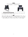
2-1.
GENERAL
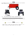
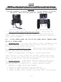
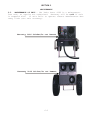
The TI4100GPU-24 (Turbo Start 4100) (Figure 2-1 and 2-2) is a compact, portable and highly versatile 24/28.5 VDC electrical ground power unit. The
unit incorporates a 208-240 single phase VAC to 28.5 VDC converter, a 24 volt
unique (dry) power cell and an internal intelligent 208 to 240 volt AC
charger to recharge the power cells. These built-in features give the Turbo
Start 4100 self-sufficiency and mobility for short-term operations without AC
electrical power or long term operations with AC electrical power. Short
term operations rely solely on power cell output and the fast recharge rates
that the unit’s internal charger provides from any standard 208-240 single
phase VAC electrical outlet. Longer term operations incorporate the continuous 100 amp output of the 208-240 VAC to 28.5 VDC converter, or a combination
of converter and power cell output to provide 24 VDC output. The following
are the unit’s four (4) main operational support capabilities:
a. 24 VDC 1500 amp peak power output for engine starting or constant (one
hour) rated power output (without a 208-240 VAC power source) for short term
trouble shooting and flexible flight line support ground power.
b. 24 VDC constant (one hour) rated power output or variable high load demand output (less than one hour) with a 208-240 single phase VAC power source
for extended maintenance (hangar) and routine flight line maintenance, ground
support power.
c. 28.5 VDC continuous rated (AC to DC converter) power output with a 208240 VAC power source for hangar and routine flight line maintenance support,
and avionics bench testing.
d. Rapid recharge of the unit’s power cells from any 208-240 VAC common
power source. This feature eliminates the need for special recharge equipment and dedicated maintenance support man-hours.
2-1
SECTION II
2.2.
DESCRIPTION
GENERAL SPECIFICATIONS
WEIGHT
UNIT:
100 lbs (50.39 Kg)
DC POWER CABLE:
8.5 lbs (3.86 Kg)
AC POWER CORD:
0.4 lbs (0.18 Kg)
INPUT POWER AC
TI4100GPU-24:
208-240 Single Phase VAC 50/60 Hz
30.0 amps max.
OUTPUT POWER DC
CONVERTER:
28.5 VDC TO 100 AMPS, 24 VDC 121 AMPS AND
ABOVE.
POWER CELLS:
24 VDC
PEAK OUTPUT:
1500 AMPS
POWER CELL
DRY, HIGH RATE DISCHARGE, RECHARGEABLE, MAINTENANCE-FREE
DC POWER CABLE
LENGTH: 8 FT
AIRCRAFT CONNECTOR: 3 PIN RECEPTACLE (MS25488)
AC POWER CORD: 8 Ft. 208-240 Single Phase VAC
2-2
UNIT DISCRIPTION AND DEMENTIONS
2-3
CHAPTER 3
OPERATING LIMITS AND RESTRICTIONS
SECTION I. GENERAL
3-1.
PURPOSE
Chapter 3 includes all important operating limits and restrictions
that must be observed for proper and safe operation of the TI4100GPU24 (Turbo Start 4100) ground power unit.
3-2.
GENERAL
The operating limitations set forth in this chapter are the direct
result of design analysis, testing, and operating experience.
Compliance with these limitations and restrictions will ensure that owners/operators obtain maximum continued capability from the Turbo
Start 4100 ground power unit.
SECTION II. OPERATIONAL RESTRICTIONS AND SAFETY LIMITS
3-3.
POWER CELL RECHARGE LIMITS
Any time the unit’s power cells are discharged the unit shall be
recharged within 24 hours to prevent performance degradation and ensure maximum life.
CAUTION
This unit is set up to recharge off of 208-240 Single Phase 50/60 Hz
VAC Power. Any other type of AC power may cause damage to the unit.
Unit’s power cells may be damaged if recharged by NiCad or Lead Acidtype battery chargers.
Power cells should only be charged by either
the TURBO START internal charger and the AC power cord furnished with
the equipment, or when connected aircraft external DC power receptacle.
3-1
3-4.
208-240 VAC CHARGER AND AC TO DC CONVERTER LIMITS
The unit is designed with a single point AC receptacle for external
power to operate both the internal charger and converter.
The units
AC voltage range can be factory set from 208 to 240 VAC SINGLE PHASE
30 AMPS MAX at 50/60 Hz depending upon customer requirements. The AC
power cord provided with the unit is the mechanism that ensures the
specified AC power source is properly supplied to the unit (see paragraph 3-5). Use no others
INTERNAL CHARGER: NO LIMIT AC power cord can remain connected
when power cells are fully charged. When the power cells are fully
charged the unit’s intelligent charger will go to a standby mode,
monitor the power cells state of charge, and only charge the power
cells to ensure they stay at maximum capacity.
INTERNAL AC TO DC CONVERTER: LIMITED (see paragraph 3-6,
3-10). AC power cord does not have to be disconnected when
verter power output is no longer
required. Once DC power
is terminated the unit’s intelligent charger will remain on
ensure power cells are charged to maximum capacity.
3-8 and
condemand
line to
CAUTION
* 8 $ 5 ’ ) 5 2 0 ,1 & 2 5 5 ( & 7
32: (5 628 5&(
3-5
Unit will be damaged if unapproved AC power is applied.
AC POWER CORD LIMITS
The AC power cord governs which AC power source the unit is set to
operate from. The Turbo Start 4100 is supplied with a single customer specified AC power cord.
3-2
WARNING
********SHOCK HAZARD POTENTIAL*********
Failure to use proper grounding can cause a potential shock hazard!
In different countries, the 240 VAC 50/60 Hz power cord may require
the use of a plug adapter to achieve plug style compatibility for
240 VAC 50/60 Hz operation. Use only adapters with proper grounding mechanism.
3-6.
ONE (1) HOUR RATE, 24 VDC CONSTANT OUTPUT
23 amp hour (without AC power connected), power cell output.
(see Figure 5-2)
123 amp hours (with AC power connected), both power cell and AC to
DC converter output.
NOTE
If power output is greater than rated amp hour rate, power cell
discharge rate will increase correspondingly.
3-7.
RATED PEAK OUTPUT (ENGINE STARTING)
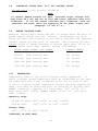
1500 peak amps at 25oC (77oF) (See Figure 5-3).
3-3
3-8.
CONTINUOUS OUTPUT RATE, 28.5 VDC CONSTANT OUTPUT
100 amp hours
(with AC power connected)
NOTE
If current demand exceeds 100 amps, converter output voltage will
drop below 28.5 VDC and two or more LED status indicator bars will
illuminate.
If all LED status indicator bars illuminate, both the
converter and power cells are supplying 24 VDC power output (see
paragraph 3-4 and 4-7.4.).
3-9.
ENGINE STARTING POWER
Operators should always ensure the unit is charged above 80% prior to
ground support engine starting.
However, circumstances may exist
during use where unit recharge is not readily available and immediate
external engine starting power is required.
The following provides
minimum states of charge necessary to provide ample power for an efficient engine start under specific current load demands.
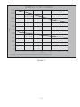
ENGINE START CURRENT LOAD DEMAND
Under 650 peak starting amps
MINIMUM CHARGE
40% charged
650-850
peak starting amps
50% charged
850-1000
peak starting amps
60% charged
1000-1200 peak starting amps
70% charged
1200-1500 peak starting amps
80% charged
3-10.
TEMPERATURE
Temperatures refer to the unit’s cold/heat soaked temperature.
A
unit’s cold/heat soaked temperature shall be established by the ambient temperature that a unit is exposed to for one (1) hour or more.
If unit’s cold/heat soaked temperature exceeds operating temperature
range, unit shall be stabilized prior to operation as follows: COLD
SOAKED, warmed for a minimum of 3 hours above +10Co (+41oF) or 2
hours above +20Co (+68oF); WARMED SOAKED, cooled for 1 hour below
+38Co (+100oF).
Operating range:
without AC power -40Co (-40oF) TO +60Co (+140oF)
with AC Power
-30Co (-22oF) TO +50Co (+124oF)
Storage range:
-60Co (-76oF) TO +60Co (+140oF)
(C0NTINUED ON NEXT PAGE)
3-4
CAUTION
Unit may be damaged if operated when unit’s cold or heat soaked temperature exceed the specified limit.
If unit is operated when cold
or heat soaked temperature limit is exceeded, a full functional check
should be accomplished prior to continued use.
NOTE
If unit should overheat, an over-temperature sensor will shut down
208-240 VAC functions (charger and converter) until unit cools to
normal operating temperatures.
3-11.
ENVIRONMENTAL
Operating any electrical equipment in the presence of moisture creates possible safety hazards and/or potential for equipment damage.
Every effort has been made, within the scope of existing technology
to prevent foreseeable safety hazards and make the Turbo Start 4100
moisture resistant to prevent damage or failure.
If the Turbo Start
4100 is exposed to moisture, preventive measures and precautions
shall be taken to:
a.
prevent accumulation of moisture on AC and DC connectors/receptacles
b.
minimize moisture entering FWD inlet and AFT outlet cooling fan vent ports
The limits and operational constraints listed below shall apply for
the following environmental (weather) conditions:
Heavy or steady rain:
OPERATION NOT RECOMMENDED
Light rain, drizzle:
NO CONVERTER OR CHARGER 208-240 VAC
fog, snow or sleet:
POWER SHALL BE APPLIED.
Unit inlet and outlet vent ports shall be covered from exposure.
Unit shall be kept horizontal.
3-5
WARNING
********SHOCK HAZARD POTENTIAL*********
Severe injury, or Death, from electrical shock is possible when personnel and/or Turbo Start 4100 are wet during use and when 208-240
VAC power is being supplied to unit.
CAUTION
Damage may occur if unit is operated after exposure to moisture
(rain, drizzle, fog, sleet or snow) or moisture contamination is suspected.
DO NOT USE until unit’s exterior and receptacles are dried.
Operation shall be restricted to use without 208-240 power cord.
DO
NOT CONNECT 208-240 VAC power cord until unit has been dried for a
MINIMUM of one (1) hour, prior to use.
Blowing sand or dust:
3-12.
Minimize exposure to sand and dust when
208-240 AC power is used. Unit shall be
kept horizontal during use.
OPERATING POSITION
Without 208-240 VAC power cord:
Horizontal or vertical.
With
Horizontal only.
208-240 VAC power cord:
Horizontal only, for proper unit ventilation, when 208-240 VAC line
cord is plugged in and exhaust fan is running.
CAUTION
Unit may be damaged if blown over by propeller, rotor or jet wash, or
accidentally knocked over.
Unit should be kept horizontal during
use.
3-6
CAUTION
Unit damage may occur if inlet and outlet vent ports are obstructed
and/or cooling air flow is restricted.
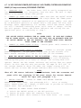
Side Vents
Front Vent/Cooling Fan
3-13.
Back Vent/Cooling Fan
UNIT OPERATION DURING AIRCRAFT FUELING/DEFUELING
Power output is restricted to 24 VDC power cell output only. DO
NOT CONNECT 208-240 VAC POWER SUPPLY.
208-240 VAC power (charger
or AC-DC converter) functions of unit shall not be operated during
any aircraft fuel handling operation.
WARNING
*******FIRE/EXPLOSION HAZARD POTENTIAL********
Severe injury, or Death, may occur from fire or explosion, as a
result of electrical sparks produced near fuel vapors.
3-7
CHAPTER 4
OPERATING
PROCEDURES
SECTION I. UNIT OPERATION
4-1.
GENERAL
Correct operation of the TI4100GPU-24 (Turbo Start 4100) includes
both pre-use and operational checks of the unit.
Knowledge of the
operating limits, restrictions, performance, unit capabilities and
functions is fundamental to correct and safe operation.
The operator
shall ensure compliance with the instructions in this manual that
affect operational safety and the warranty of the unit.
4-2.
OPERATING LIMITS AND RESTRICTIONS
The minimum, maximum and normal operating ranges result from careful
engineering and evaluation of test data.
These limitations must be
adhered to during all phases of operation. Refer to Chapter 3, Section II, OPERATING LIMITS AND RESTRICTIONS, for detailed information.
4-3.
PERFORMANCE
Refer to Chapter 5, PERFORMANCE DATA to determine the capability of
the Turbo Start.
Consideration must be given to changes in performance resulting from variations in ambient temperature, mode of operation, state of charge (with or without 208-240 VAC power), and
aircraft DC bus system inefficiency (voltage drops).
4-1
SECTION II. OPERATING PROCEDURES
4-4. OPERATING PROCEDURES
This section deals with normal procedures, and includes all steps
necessary to ensure safe and efficient operation of the TI4100GPU-24
(Turbo Start 4100). As experience is gained with the Turbo Start
4100, the user will be able to maximize the unit’s unique capabilities to enhance the flexibility of aircraft maintenance and support
operations.
NOTE
When the TURBO START 4100 is not in use, it should always remain
plugged into a suitable AC power source to insure operational readiness at all times. REMEMBER, when the AC line cord is plugged in, the
unit must be placed in the horizontal position to allow the cooling
fan to operate properly!
4-5. BEFORE OPERATION CHECK
1. CHECK UNIT FOR STATE OF CHARGE- Ensure power unit is connected to
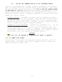
a suitable AC power source (208-240 Single Phase VAC 30AMP max outlet). The LED status indicator should show a single green bar ( last
LED bar ) to indicate the unit’s power cells are fully charged.
NOTE:
A full charge is indicated by Either a steady lighted green bar or a
blinking green bar at the bottom of the bar graph column The fan will
also exhibit ratcheting but will not come on when the unit is fully
charged.
STATUS
2. CHECK UNIT FOR EVIDENCE OF DAMAGE - Check for dents, punctures,
case distortion or misalignment, cracked or loose connectors, and
that cooling fan is functioning.
4-2
CAUTION
REMEMBER, when the AC line cord is plugged in, the unit must be
placed in the horizontal position to allow the cooling fan to operate
properly!
Unit may overheat if cooling fan fails. Do not operate if cooling
fan fails. (More than one green bar present on bar graph)
Front Vent/Cooling Fan
Back Vent/Cooling Fan
3. CHECK DC POWER CABLE/CONNECTORS FOR DAMAGE - Check cable for
cuts, chafing or evidence of being crushed.
Check connectors for
cracks, cuts, distortions, excessive wear, broken/loose fasteners or
loose cable attachment.
4-6. 24 VDC GROUND POWER (NO 208-240 VAC POWER SUPPLY) ENGINE STARTING OR DC SYSTEM POWER
1. TRANSPORT UNIT - The Turbo Start 4100 is easily transported using
the wheels that are incorporated into the unit. The unit is engineered to be pushed rather than pulled.
2. CONNECT DC POWER CABLE TO UNIT - Ensure power cable connector is
fully seated into unit’s connector.
Set the unit down horizontally
ensuring vent ports are unblocked.
3.
CONNECT DC POWER CABLE TO AIRCRAFT - Ensure ground power
cable connector is fully seated into aircraft ground power receptacle. DC bus power should come on and aircraft volt meter should
indicate 24 VDC to 23.5 VDC (23 VDC minimum).
4. ENGINE STARTING - Check power cable for security and correct
installation prior to engine start.
Follow ground power engine
starting procedure as specified in aircraft operators manual.
5.
REMOVING DC POWER SUPPLY FROM AIRCRAFT
a. Switch the ON/OFF switch to the OFF position
b. Remove DC power cable GPU connector from aircraft.
c. Remove DC power cable connector from Turbo Start (if necessary).
4-3
4-7. 24 VDC GROUND POWER (WITH 208/240 VAC POWER) SYSTEM HIGH POWER DEMAND (101 amps and above) OR ENGINE STARTING.
1. TRANSPORT UNIT - The Turbo Start 4100 is easily transported using the wheels that are incorporate into the unit. The unit is engineered to be pushed rather than pulled.
2. CONNECT AC POWER CORD TO UNIT - Make sure that the On/Off switch
is in the Off position. Ensure 208-240 Single Phase VAC 30AMP power
cord is properly connected to an approved AC power supply. Unit shall
be in Horizontal position to ensure unit’s vent ports are free from
blockage. After approximately 5-8 seconds, unit’s LED status indicator will illuminate indicating power cells state of charge. Cooling
fan will operate. Ensure LED status indicator and cooling fan are
operational prior to continuing to step 3.
NOTE
THE ON/OFF SWITCH CONTROLS THE AC POWER INPUT. IT DOES NOT CONTROL
THE DC POWER OUTPUT. IF YOU PLUG THE UNIT INTO AN AIRCRAFT WITH THE
AC ON/OFF SWITCH IN THE OFF POSITION, THE UNIT WILL STILL PROVIDE
24VDC POWER TO THE AIRCRAFT.
3. CONNECT DC POWER CABLE TO UNIT - Ensure power cable connector is
fully seated into unit’s receptacle.
4. CONNECT DC POWER CABLE TO AIRCRAFT - Connect to aircraft ground
power receptacle. DC bus power should come on and aircraft volt
meter should indicate 27.5 VDC to 23.5 VDC (23 VDC minimum).
5. MOVE THE ON/OFF SWITCH TO THE ON POSITION - After approximately
2-3 seconds, the unit’s LED bar status indicator will illuminate,
indicating the power cells state of charge. The cooling fans will
operate. Ensure the LED status indicator and cooling fans are operational. At this time the unit can provide 100 amps at 28.5 VDC. If
the current demand is above 100 amps, the output voltage will decrease and two or more LED status indicator bars will illuminate.
NOTE
When all LED status indicator bars illuminate, both the converter and
power cells are supplying 24 VDC power output for current demands
above 101 amps (see paragraph 3-4).
6.
ENGINE STARTING - UNPLUG AC POWER CORD BEFORE STARTING
ENGINE WITH TURBO START. (see paragraph 4-6.).
Prior to engine
start, ensure power cell charge is sufficient to provide an efficient
engine start (see paragraph 3-7).
7.
REMOVING DC POWER SUPPLY FROM AIRCRAFT
a. Switch the ON/OFF switch to the OFF position
b. Remove DC power cable GPU connector from aircraft.
c. Remove DC power cable connector from Turbo Start (if
sary).
4-4
neces-
4-8 28.5 VDC GROUND POWER (WITH 208/240 VAC POWER) SYSTEM LOW
DEMAND (100 amps or less).
POWER
1. TRANSPORT UNIT - The Turbo Start 4100 is easily transported using the wheels that are incorporated into the unit. The unit is engineered to be pushed rather than pulled.
2. CONNECT AC POWER CORD TO UNIT - Make sure that the On/Off switch
is in the Off position. Ensure 208-240 Single Phase VAC 30AMP power
cord is properly connected to an approved AC power supply. Unit shall
be in Horizontal position to ensure unit’s vent ports are free from
blockage. After approximately 5-8 seconds, unit’s LED status indicator will illuminate indicating power cells state of charge. Cooling
fan will operate. Ensure LED status indicator and cooling fan are
operational prior to continuing to step 3.
NOTE
THE ON/OFF SWITCH CONTROLS THE AC POWER INPUT. IT DOES NOT CONTROL
THE DC POWER OUTPUT. IF YOU PLUG THE UNIT INTO AN AIRCRAFT WITH THE
AC ON/OFF SWITCH IN THE OFF POSITION, THE UNIT WILL STILL PROVIDE
24VDC POWER TO THE AIRCRAFT.
3. CONNECT DC POWER CABLE TO UNIT - Ensure power cable connector is
fully seated into unit’s receptacle.
4. CONNECT DC POWER CABLE TO AIRCRAFT - Connect to aircraft ground
power receptacle. DC bus power should come on and aircraft volt
meter should indicate 27.5 VDC to 23.5 VDC (23 VDC minimum).
5. MOVE THE ON/OFF SWITCH TO THE ON POSITION - After approximately
2-3 seconds, the unit’s LED bar status indicator will illuminate,
indicating the power cells state of charge. The cooling fans will
operate. Ensure the LED status indicator and cooling fans are operational. At this time the unit can provide 100 amps at 28.5 VDC. If
the current demand is above 100 amps, the output voltage will decrease and two or more LED status indicator bars will illuminate.
7.
REMOVING DC POWER SUPPLY FROM AIRCRAFT
a. Switch the ON/OFF switch to the OFF position
b. Remove DC power cable GPU connector from aircraft.
c. Remove DC power cable connector from Turbo Start
(if
sary).
4-9
neces-
POWER CELL RECHARGE
1. CONNECT AC POWER CORD TO UNIT - Unit shall be in horizontal position to ensure unit’s vent ports are free from blockage. - Ensure
208-240 VAC power cord is properly connected to an approved AC power
supply.
After approximately 5-8 seconds, ensure unit’s LED status
indicator illuminates indicating power cell state of charge and cooling fan is operating.
4-5
CAUTION
Unit may overheat if cooling fan fails.
Do not operate if cooling fan fails.
Front Vent/Cooling Fan
Back Vent/Cooling Fan
2. CHECK FOR FULL CHARGE INDICATION - After 30 minutes, LED charge
indicator should show a single steady or flashing green LED bar when
fully charged, the last LED bar. AC power may be left connected to
unit when power cells are fully charged.
NOTE
Under a full charge, two things will be observable with the unit. A
non-blinking lighted green bar or a blinking green bar at the bottom
of the bar graph, both indicate a full charge. Also the fan will display ratcheting but not come on when the unit is fully charged.
4-6
SECTION III.
FUNCTIONAL CHECK PROCEDURES
4-10.
FUNCTIONAL CHECK PROCEDURES
This section deals with normal functional check procedures, and includes all steps necessary to ensure the Turbo Start 4100 is functioning within specific operational parameters prior to operational
use. As users gain experience with the Turbo Start 4100, they will
incorporate these functional checks as a routine practice.
4-11.
REQUIRED EQUIPMENT FOR FUNCTIONAL CHECK.
FLUKE OR EQUIVALENT TYPE DIGITAL MULTIMETER.
4-12.
DC FUNCTIONAL CHECK.
1. CHECK UNIT FOR EVIDENCE OF DAMAGE - Check for dents, punctures,
case distortion or misalignment, cracked or loose connectors. If no
damage is evident proceed to step two.
IF DAMAGE IS EVIDENT contact distributor or manufacturer.
2. ENSURE UNIT IS NOT PLUGGED INTO 208-240 VDC. Unplug AC power if
plugged in.
3. CHECK UNIT INTERNAL RESISTANCE (TEST FOR SHORTS) - Better than 10
Megohms. Ensure no short exists.
Negative (-) DC receptacle terminal and unit case.
Positive (+) DC receptacle terminal and unit case.
4.
CHECK DC VOLTAGE READING AT DC RECEPTACLE TERMINALS.
24 to 25.5 VDC depending on state of charge.
5. PLUG IN 208-240 POWER CORD.-Ensure power unit is connected to a
suitable AC power source 208-240 Single Phase 50/60 Hz.
6. CHECK UNIT FOR STATE OF CHARGE - Unit shall be in horizontal
position to ensure unit’s vent ports are free from blockage. After
approximately 5-8 seconds, unit LED status indicator shall illuminate
indicating power cell state of charge.
Ensure LED status indicator
and cooling fan are operational. Prior to continuing to step 7, the
LED status indicator should show a single green bar (last LED bar) to
indicate the unit’s power cells are fully charged. Also under full
charge the fan will ratchet but not enable.
4−7
NOTE
Under a full charge, the last green LED bar may blink. This does not
indicate a malfunction. A non-blinking lighted green bar or a blinking green bar at the bottom of the LED column, both indicate a full
charge.
7. CHECK DC VOLTAGE READING AT DC RECEPTACLE TERMINALS.
power cells are fully charged (see step 6.)
Ensure
28.5 (+-0.57 VDC) with power cells at full state of charge.
8. FUNCTIONAL CHECK COMPLETE - Unit should remain plugged in to AC
power until required for use.
4−8
CHAPTER 5
PERFORMANCE DATA
SECTION 1. INTRODUCTION
5-1.
PURPOSE
This chapter provides performance data for the TI4100GPU-24 (Turbo
Start 4100).
Continual reference to this information will enable the
user to obtain maximum performance, utilization and service life from
the Turbo Start.
Although maximum performance is not always required,
regular referral to this chapter is recommended for the following reasons:
a.
To generate knowledge of unit’s performance margins to enable
the operator to make sound judgment when unexpected conditions or
alternate operational requirements are encountered.
b.
To enable the user to readily recognize situations requiring
maximum performance.
c.
To gain experience in accurately estimating the effects of
variables for which data is not presented.
d. To help the operator determine if an aircraft system malfunction exists by comparing actual performance with expected performance.
NOTE
The information provided in this chapter is primarily intended for
operational planning and is most useful when planning operations under
unfamiliar conditions or environmental extremes.
The data may also be
used to establish local operating procedures and to ensure
unit’s
operational life is maximized.
5-2.
GENERAL
The data presented covers the maximum range of conditions and performance that can reasonably be expected.
In each area of performance,
the effects of temperature and DC electrical load demand relating to
the ground power support requirements are presented.
Wherever practical, data is presented conservatively.
However, NO GENERAL CONSERVATISM HAS BEEN APPLIED.
All performance data presented is within the
applicable limits of the Turbo Start.
5-1
SECTION II
DATA CRITERIA
5-3
DATA BASIS
The type of data used is indicated at the bottom of each performance
chart under DATA BASIS. The applicable report and date of the data
are also given. The data provided generally are based on one of
three categories:
a.
Derived From Actual Controlled Testing.
obtained on a similar unit type.
Controlled test data
b. Calculated Data. Data based on tests, but not on a similar
unit type placed under a controlled test.
c. Estimated Data. Data based on estimates using rules of physics, mathematics, and electrical engineering principles and concepts, but not verified by tests.
5-4.
SPECIFIC CONDITIONS
The data presented are accurate only for specific conditions listed
under the title of each chart or graph. Variables for which data are
not presented, but which may affect that phase of performance, are
discussed in associated text.
Where data are available or reasonable
estimates can be made, the amount that each variable affects performance will be given.
5-5.
GENERAL CONDITIONS
In addition to the specific conditions, the following general conditions are applicable to the performance data.
a.
Variation in Aircraft.
Power demand differences between individual aircraft of the same make and model are known to exist due
to variations in DC electrical system efficiency.
These differences, however, are considered insignificant and are not individually accounted for.
b.
Ground Support and Aircraft Instrument Variations. The data
shown in the performance charts do not account for instrument tolerance differences or inaccuracies.
5-6.
DEFINITIONS OF ABBREVIATIONS
Unless otherwise indicated, the abbreviations defined in Chapter 1
will be applicable to all charts and graphs in this chapter.
5-2
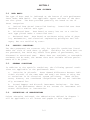
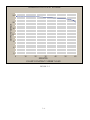
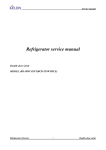
FIGURE 5-1
5-3
TI41000GPU-24 OUTPUT VOLTAGE
24
OUTPUT VOLTAGE
20
16
12
8
4
0
0
10
20
30
40
MINUTES
23 AMP CONSTANT CURRENT LOAD
FIGURE 5-2
5-4
50
60
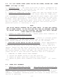
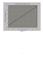
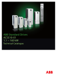
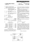
MAXIMUM OUTPUT CURRENT
***
1500
1350
****
0
** **
(+25 C Temp)
1200
* ***
1050
*****
*****
AMPS
900
750
* * *****
600
0
*********
(-29 C Temp)
450
*****
**********
****
300
150
0
0
5
10
15
20
SECONDS
Calculations based on actual test data at Pratt-Whitney Canada on 30 March 1992.
FIGURE 5-3
5-5
25
30
CHAPTER 6
CARE AND MAINTENANCE
SECTION I.
6-1.
UNIT CARE
GENERAL
Although the TI4100GPU-24 (Turbo Start 4100) has been ruggedized
and made weather resistant within the scope of unit’s intended use,
it is essential that good general care be taken to maintain unit in
good operating condition and to maximize unit’s operational life.
6-2. AFTER USE - Unit should be protected from the environmental
elements and man made hazards. Ideally unit should be secured in a
building or shed. Most importantly, unit shall be fully covered if
stored exposed to environmental elements.
1.
KEEP UNIT RECEPTACLES AND OUTER CASE CLEAN - wipe with dry cloth.
2.
KEEP FOREIGN OBJECTS OUT OF UNIT - Cover unit to prevent
foreign objects, water, and dirt from entering vent ports and receptacles.
3.
KEEP FROM PROLONGED EXPOSURE TO EXTREMELY DAMP ENVIRONMENTS
Cover unit to prevent migration of moisture. If unit is operated in
extremely damp environments unit should be kept in an environmentally
controlled building.
4. KEEP UNIT PLUGGED INTO AC POWER SUPPLY WHEN NOT IN USE.
To
maximize life of power cells and to ensure unit is always ready for
use, unit should remained plugged in to AC power when not in use.
NEVER LET DISCHARGED UNIT SIT FOR MORE THAN 24 HOURS WITHOUT FULLY
RECHARGING POWER CELLS.
5. PROTECT DC POWER CABLE AND AC POWER CORD FROM DAMAGE - Prevent
from being cut, gouged, crushed, dragged or otherwise abused.
6-1
SECTION II.
MAINTENANCE
6-3. MAINTENANCE OF UNIT - The Turbo Start 4100 is a maintenancefree unit, no repairs are authorized. Warranty will be void if unit
is tampered with.
If unit fails to operate contact Manufactures Warranty Claim (see unit warranty).
Warranty Void Sticker/Do not Remove
Warranty Void Sticker/Do not Remove
6-2
Chapter 7
Push To Test Modification
General Information And Operation
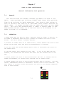
7-1.
General
THIS MODIFICATION HAS BECOME STANDARD EQUIPMENT FOR EACH OF OUR
UNITS.
BOTH MILITARY AND CIVILIAN CLIENTS HAVE FOUND THIS MODIFICATION TO BE CRITICAL TO THEIR OPERATION. THE PUSH TO TEST BUTTON IS
USED TO INDICATE THE CAPACITY OF THE POWER CELLS WITHOUT APPLYING AC
INPUT POWER. IT ALLOWS THE END USER TO CHECK THE STATUS OF THE POWER
CELLS. THIS LETS THE OPERATOR KNOW IF THERE IS ENOUGH POWER TO PERFORM ANOTHER ENGINE START, OR IF THE UNIT HAS TO BE RETURNED TO AC
POWER TO ALLOW IT TO RECHARGE.
7-2.
OPERATION
1) MAKE SURE THAT YOU WAIT AT LEAST 2 MINUTES AFTER AC POWER IS APPLIED, OR
DC POWER IS EXTRACTED FROM THE UNIT, BEFORE YOU DEPRESS THE PUSH TO TEST
BUTTON. THIS WILL ENSURE A CORRECT READING.
2) WITHOUT AC POWER INPUT OR DC POWER OUTPUT, SIMPLY DEPRESS THE PUSH TO TEST
BUTTON ON THE FACE PLATE AND HOLD FOR APPROXIMATELY 15 SECONDS.
3) AT THIS TIME THE LED BAR GRAPH SHOULD LIGHT UP INDICATING THE STATUS OF
THE POWER CELLS.
4) THE FAN SHOULD ALSO OPERATE AT THIS TIME. IF YOU DO NOT HEAR THE FAN
RUNNING, STOP DEPRESSING THE BUTTON AND CHECK FOR ANY OBSTRUCTIONS TO THE
FAN.
5) NEVER DEPRESS THE PUSH TO TEST BUTTON WHILE THE UNIT IS PLUGGED INTO AC
POWER FOR RECHARGE, OR PLUGGED INTO AIRCRAFT FOR DC POWER OUTPUT.
6) NEVER DEPRESS THE PUSH TO TEST BUTTON FOR MORE THAN 30 SECONDS. THIS MAY
CAUSE A TEMPERATURE SENSOR TO TEMPORARILY DISRUPT PUSH TO TEST FUNCTION. (IF
THIS SENSOR IS TRIPPED, ALLOW TEN MINUTES FOR UNIT TO COOL BEFORE OPERATING
PUSH TO TEST BUTTON.)
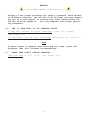
STATUS
7-1
R
0
Y
1/2
G
OK
Chapter 8
ON/OFF SWITCH
General Information And Operation
7-1.
General
The TI4100GPU-24 comes equipped with an On/Off switch on the face
plate, This switch controls AC power input only, It does not control
the DC output power to the aircraft, Whenever the unit is plugged
into an aircraft, it is supplying DC power, The ON/OFF switch located
on the face plate does not have any control on the DC output power
funtion
8-2.
OPERATION
1) Place the On/Off switch in the Off position.
2) Plug the unit into 208/240 single phase 30 AMP AC power.
3) Connect the DC cord to the Aircraft or vehicle. ( At this time the
unit will be providing 24 VDC Power)
4) Place the On/Off switch to the on position. After 2-3 seconds, The
led bar graph should light and the fans should begin to operate.
5) If the fans and led bar graph do not operate, than check the AC
outlet for power.
NOTE
The power cells will only recharge while the On/Off
switch is in the on position. The On/Off switch does
not control the DC output power.
8-1
PARAGRAPH INDEX
208-240 VAC Charger and AC to DC Converter Limits,
3-4
24 VDC Ground Power (NO 208-240 VAC Power Supply) Engine Starting or
DC system Power, 4-6
24 VDC Ground Power (With 208-240 VAC Power) System High Power Demand
(21-1500 Amps) or Engine Starting,
4-7
28.5 VDC Ground Power (with 208-240 VAC Power) System Low Power Demand (100 Amps or less), 4-8
Abbreviations,
1-5
AC Power Cord Limits,
After Use,
3-5
6-2
Appendix A Line Cord Table
Before Operation Check,
4-5
Continuous Output Rate, 28.5 VDC Constant Output,
Data Basis,
5-3
DC Functional Check,
4-12
Definitions of Abbreviations,
Dimensions, Figure
2-1
Discharge Load Curve, Figure
Description
5-6
5-2
1-3
Engine Starting Power,
Environmental,
3-9
3-11
Functional Check Procedures,
Forms and Records,
1-6
General, Chapter 1,
1-1
General, Chapter 2,
2-1
General, Chapter 3,
3-2
General, Chapter 4,
4-1
General, Chapter 5,
5-2
General, Chapter 6,
6-1
General Conditions,
5-5
General Details, Figure
2-2
General Specifications,
2-2
4-10
3-8
PARAGRAPH INDEX
Index,
1-4
Maintenance of Unit,
6-3
Maximum Output Current, Figure
5-3
On/Off Switch General, 8-1
On/Off Switch Operation, 8-2
One (1) Hour Rate, 24 VDC Constant Output,
Operating Limits and Restrictions,
Operating Procedures,
Operating Position,
Performance,
4-2
4-4
3-12
4-3
Power Cell Recharge,
4-9
Power Cell Recharge Limits,
Purpose, Chapter 3,
3-1
Purpose, Chapter 5,
5-1
3-3
Rated Peak Output (Engine Starting),
3-7
Required Equipment for Functional Check,
Specific Conditions,
Temperature,
3-6
4-11
5-4
3-10
Temperature Conversion Chart, Figure
5-1
Unit Operation During Aircraft Fueling/Defueling,
Use of Word Shall, Should and May,
Warning, Caution and Notes Defined,
1-7
1-2
3-13