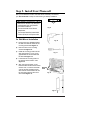
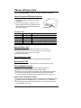
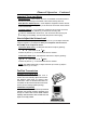
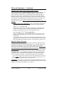
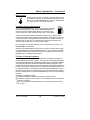
1
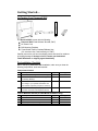
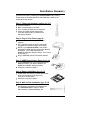
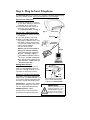
X CELL S PHONE PHONECELL SX3i AMPS FIXED WIRELESS TERMINAL USER MANUAL Total communications freedom at your fingertips...voice/fax/data. 12/08/99 Part No. 56016602 Introduction Phone(s) Fax Machine Computer Modem ELL SX PHONEC l l AC Power Thank you for choosing the Phonecell® SX3 Fixed Wireless Terminal (FWT) from Telular. This innovative product lets you connect up to five pieces of standard telephone equipment into a cellular network for total communications flexibility. Please follow this guide to unpack, set up and operate your new Phonecell safely and properly. Telular is proud to welcome you as a valued customer. Your satisfaction is our most important concern. Telular Corporation Corporate Headquarters 647 North Lakeview Parkway Vernon Hills, Illinois 60061, USA TECHNICAL SUPPORT Tel: 847-247-9400 · Fax: 847-247-0021 E-mail: [email protected] · http://www.telular.com Patents: Telular Corporation products are protected and manufactured under one or more of the following U.S. patents and related international patents and patents pending relating thereto: 4,658,096; 4,737,975; 4,775,997; 4,868,519; 4,922,517; 5,134,651; 5,361,297; 5,469,494; 5,046,085; 5,715,296; 5,812,637; 5,859,894; 5,946,616; 5,966,428; 6,035,220. Trademarks: Telular Corporation owns the following registered trademarks: TELULAR, TELULAR plus design, CELJACK, PCSone, TELCEL, HEXAGON LOGO, PHONECELL, CELSERV, TELGUARD, and CPX. Part No. 56016602 PHONECELL SX3i AMPS ©2000 Telular Corporation, all rights reserved. 2 USER MANUAL 12/08/99 Table of Contents Introduction...............................................................................................2 Technical Support ...................................................................................2 Getting Started Unpacking the Phonecell SX3i ...............................................................4 Pre-Installation Checklist ........................................................................4 Installation Summary ...............................................................................5 Step 1. Choose an Antenna Location.....................................................6 How to Connect the Antenna .................................................................7 Step 2. Plug in Your Telephone ...............................................................8 Connect Your Telephone ........................................................................8 Place a Call Adjust Your FWT .............................................................8 Connecting Additional Phones & Equipment..........................................8 Step 3. NAM/Phone Number Setup....................................................9-11 Optional A-Key (Authentication Code) Setup .......................................11 Step 4. Optional Battery Installation ...............................................12-13 Step 5. Install Your Phonecell Wall-Mount Installation .........................................................................14 Desktop/Tabletop Installation................................................................15 Phonecell SX3i Operation How to Use the LED Status Indicator...................................................16 How to Place a Call ..............................................................................16 How to Receive a Call ..........................................................................16 How to End a Call ................................................................................16 The Hookflash Function .......................................................................16 Important Tones and Alerts...................................................................17 How to Adjust the Volume Level...........................................................17 Fax/Data Transmission.........................................................................17 Variable Dial Time (Auto SEND Delay) Option.....................................18 Special Cellular Services.................................................................18-19 Data After SEND (In-Call DTMF Signaling) Option ..............................19 Zero Dial Delay for Frequently Called Numbers ..................................19 Phonecell SX3i Troubleshooting...........................................................20 Safety Information.............................................................................21-23 AMPS Technician Programming How to Enter the Programming Mode..................................................24 How to Set the Access Overload Class (ACCOLC) .........................25 How to Set the Access Method (EX) Option ....................................25 How to Set the Roam Option............................................................25 How to Set the Dial Tone After Remote On-Hook Option ................25 How to Set the Post-Receiver Off-Hook (ROH) Option....................26 How to Set the Pulse Dial Option .....................................................26 How to Initiate a Ring-Back Request................................................26 How to Restore the Factory Default Settings ...................................26 How to Enable/Disable the Zero Dial Delay Option .........................26 PHONECELL SX3i AMPS 3 USER MANUAL 12/08/99 Getting Started... Un-Packing Your Phonecell SX3i Ë ELL SX PHONEC Í Ì Ê The Phonecell SX3i comes with the following: Ê Phonecell SX3i Fixed Wireless Terminal (FWT) Ë AC Power Cord Ì Drill Mounting Template Í Three Rubber Feet for Desktop/Tabletop Use* (*Do not attach feet if wall-mounting the FWT.) Carefully remove the unit from the shipping carton and check for evidence of shipping damage. If damage is found, contact your Authorized Telular Distributor or shipping agent immediately. Pre-Installation Checklist Before attempting Phonecell SX3i installation, make sure you have the following components, tools and materials. Components Needed Qty. 1 2 1 1 Description Antenna (Spike, Magnetic-Mount, or Yagi) 6-Volt, 4.5 AH Lead-Acid Batteries (Optional for Battery Backup) RJ-11 Modular Phone Cord (Length varies according to your specific installation and the number of phones you plan to connect) Supplied Not Supplied 4 4 4 RJ-11 Phone Line Splitter (if you plan to connect more than one telephone device) 4 Tools & Materials Needed (for Wall-Mount Installation Only) Qty. 1 1 2 Description Drill & Drill Bit Screwdriver 11/2-inch (3.75 cm) Mounting Screws PHONECELL SX3i AMPS 4 Supplied Not Supplied 4 4 4 USER MANUAL 12/08/99 Installation Summary There are five steps to installing the Phonecell SX3i FWT properly. These steps are summarized below and explained in detail in the remainder of this manual. Step 1. Choose an Antenna Location (pg. 6-7) · · · · Choose a location. Next, connect power to the FWT. Then, connect the antenna (not supplied). Check the cellular signal strength and move the antenna until you achieve the best signal possible. Step 2. Plug In Your Phone (page 8) · Once the antenna is connected, hook up a phone. · Then, make a test call to check noise levels, and adjust the antenna location accordingly. · NOTE: If your Phonecell SX3i is not pre-programmed for NAM (Number Assignment Module) information, youll need to perform the NAM/Phone Number Setup in Step 3. Then, return to this step (2). · Plug in additional phones, Fax and/or Modem. Step 3. NAM/Phone Number Setup (pg. 9-11) · If your Phonecell was not pre-programmed for NAM information, you need to perform the NAM/Phone Number Setup procedure. · Otherwise, continue to Step 4. F Step 4. Battery Installation (pg. 12-13) · Follow these instructions to install optional batteries (not included) for backup in the event of AC power failure. · Otherwise, continue to Step 5. Step 5. Wall or Desk Installation (pg. 14-15) · After youve selected a location and made all the necessary connections and adjustments, your Phonecell SX3i is ready for either wall-mounting or desktop/tabletop use. PHONECELL SX3i AMPS 5 USER MANUAL 12/08/99 Step 1. Choose an Antenna Location Your Phonecell SX3 receives operating commands from the cellular network and relies upon signal strength for proper operation. Therefore, finding an antenna location with good signal strength is critical for call quality. ANTENNA LOCATION TIPS: · Locate the antenna above ground and as close to windows (or exterior walls) as possible see Fig. 1. · Try to install the antenna in an uninhabited area (i.e. closets, attics, etc.) to ensure a minimum separation of 16 inches (40 cm) between the antenna and the inhabitants. · In low signal areas, the antenna should be mounted on the buildings exterior see Fig. 2. · High-gain (Yagi) antennas must be directed toward your service providers nearest cellular tower. · Spike antennas must be pointed upward. · Keep antenna cable as short as possible long cable runs affect call quality. · Never splice antenna cable. Fig. 1 Optional spike antenna pointed upward and located near the window for optimum signal strength. Coaxial Cable Fig. 2 Optional high-gain antenna installed on the buildings exterior. Always direct the antenna toward the nearest cell tower of your service provider. PHONECELL SX3i AMPS 6 USER MANUAL 12/08/99 Antenna Location & Setup Continued How to Connect the Antenna: Fig. 3 1) Connect the AC line cord from the power port on the front of the FWT to the AC power source see Figure 3. OR if an external DC power source is used, connect an optional DC input cable to the DC Input port. Power Switch 2) Turn on the FWT power using the power switch. After approximately 10 seconds, the LED indicator on the front of the FWT should turn RED. DC Port LED Indicator AC Port AC Line Cord 3) Connect an antenna to the TNC antenna connector on top of the FWT see Figure 4. l AC Power l 4) Move the antenna from one location to another until you achieve the best signal strength possible. ANTENNA TIP: Many things can obstruct the cellular signal, and moving the antenna as little as one meter (3 feet) can dramatically improve signal strength and call reception. Test the cellular signal strength by checking the LED indicator on the front of your Phonecell: · Solid RED = No Service · Solid YELLOW = Moderate signal strength · Solid GREEN = Good signal strength. 5) When youre getting a strong Optional High-Gain Optional MagneticMount Optional Spike TNC Antenna Connector (GREEN) signal, youre ready for the next step connecting a phone and making a call. Fig. 4 WARNING! ! Never operate your Phonecell when any person is within 16 inches (40 cm) of the antenna. PHONECELL SX3i AMPS 7 ELL SX PHONEC Power Switch LED Indicator USER MANUAL 12/08/99 Step 2. Plug In Your Telephone Your Phonecell SX3 lets you connect up to 5 pieces of standard telephone equipment into a cellular network. Follow the steps below for quick installation. Connect Your Telephone: 1) Locate the modular (RJ-11) line port on your phone and plug in one end of a standard (RJ-11) phone cord. 2) Connect the other end of the cord to the RJ-11 port on the front of your Phonecell SX3i see Fig. 5. Place a Call Adjust Your FWT: Fig. 5 1) Pick up the phone receiver and listen for dial tone. 2) If you hear dial tone, make a call. 3) While youre talking with the other party, listen for static and echo. If you hear either, move the antenna until you find the spot where voice conversation is strong, and static and echo are minimized. NOTE: If you are unsuccessful in dialing out, verify the following: To RJ-11 Port Phone Cord To Phone(s) To Fa x To Modem · The antenna location needs to be adjusted see Step 1, page 6-7. · The NAM/Phone Number needs to be set up see Step 3, page 9-11. · Your cellular phone number has not been activated contact your cellular service provider. Adding More Phones? Plug in an RJ-11 line splitter (not supplied) to connect additional phones to your FWT see Fig. 6. NOTE: you can only make one phone call at a time. Line Splitter Additional Telephone Equipment: Phone Cords If you plan to use a device other than a telephone with your Phonecell SX3 (such as a modem), make sure that device will work with a normal wired telephone line. Fig. 6 Optional RJ-11 Line Splitter lets you connect additional phone equipment to your Phonecell SX3i. Fax Machines Connect a fax machine the same way it needs to be set up for use on a regular wired telephone line. PBX/KSU Systems PABX installation should only be performed by experienced telephone technicians. PHONECELL SX3i AMPS IMPORTANT! ! 8 RJ-11 Port Make sure the wiring from the telephone equipment to your Phonecell SX3 is properly protected from all transient voltages, including lightning. USER MANUAL 12/08/99 Step 3. NAM/Phone Number Setup IMPORTANT! ! If your Phonecell was NOT pre-programmed for NAM (Number Assignment Module/Phone Number) information, follow the steps below. Otherwise, continue to STEP 4, pages 12,13. You can program the Phonecell SX3 with an ordinary tone-dial (DTMF) telephone, which is sometimes referred to as a POTS (Plain Old Telephone Service) phone. NOTE: this programming mode is not accessible while you're in a call. Step #1 - Pick up the POTS handset and listen for a tone (either a steady dial tone or a beeping no-service tone). Step #2 - Enter the Master-Programming mode by pressing: # 0 12344321# F * * Step #3 - Press: F # F # The dial tone should change to a different, steady Programming tone and the LED indicator on the front of your Phonecell should blink alternately RED and GREEN to indicate that youre now in the programming mode. You now have two minutes to begin the programming steps below. *1*___ ___ ____# The spaces represent your 10-digit telephone number. (This is also called a Mobile Identification Number, or MIN.) If you enter the number incorrectly, you'll hear three short tones followed by the programming tone; if correct, you'll hear the programming tone again. Step #4 - Press: *5*_____# The spaces represent your 1- to 5-digit System Identifier (SID), which ranges from 0 to 32,767. This information identifies your cellular service provider. (For example, to set up 555, enter #*5*555#.) If you enter the SID incorrectly, you'll hear three short tones followed by the programming tone; if correct, you'll hear the programming tone again. NOTE: depending upon whether you enter an odd SID or an even SID, the Phonecell will automatically set the remaining NAM parameters to AMPS standards as shown in the table below. Automatically Set NAM Parameters Initial Dedicated Control Channel First Paging Channel Number of Dedicated Control Channels Preferred System Roam Option (to override, see page 25) AMPS Standards Odd SID Even SID 333 334 333 334 21 21 A B Enabled Enabled If you need to override any of the settings, continue with steps 5 - 8. Otherwise, hang up. The flashing LED indicator will become solid GREEN. Phone number setup is complete. Continued... PHONECELL SX3i AMPS 9 USER MANUAL 12/08/99 NAM/Phone Number Setup Override Commands NOTE: The following NAM Parameters are automatically set by the SID value in step 4 on the previous page. These steps 5 - 7 are only needed if you want to override the standard AMPS settings listed on the previous page. Otherwise, continue to Step 4 Optional Battery Installation on pages 12,13. Step #5a - How to Override the Initial Dedicated Control Channel and First Paging Channel. If you have an A cellular service provider with an odd SID (System Identifier), enter the following 2-part key sequence. Otherwise, continue to Step #5b. 1) First press: 2) Next press: F F # # * 24 * _ _ _ _ # *4*____# (Note: enter the same 1- to 4-digit channel in both steps above.) The spaces represent your 1- to 4-digit Initial Dedicated Control Channel and First Paging Channel. When you turn on your Phonecell, these channels help the service provider find you and vice-versa. NOTE: The default setting is channel 333 for "A" service providers. To change the setting, you must enter a 1- to 4-digit number in the range of 0 to 1023. (For example, to set up channel 565, enter #*24*565#.) If you enter the channel incorrectly, you'll hear three short tones followed by the programming tone; if correct, you'll hear the programming tone again. Step #5b - If you have a B cellular service provider with an even SID (System Identifier), enter the following 2-part key sequence. 1) First press: 2) Next press: F F # * 25 * _ _ _ _ # # *4*____# (Note: enter the same 1- to 4-digit channel in both steps above.) The spaces represent your 1- to 4-digit Initial Dedicated Control Channel and First Paging Channel. When you turn on your Phonecell, these channels help the service provider find you and vice-versa. NOTE: the default setting is channel 334 for "B" service providers. To change the setting, you must enter a 1- to 4-digit number in the range of 0 to 1023. (For example, to set up channel 566, enter #*25*566#.) If you enter the channel incorrectly, you'll hear three short tones followed by the programming tone; if correct, you'll hear the programming tone again. Continued... PHONECELL SX3i AMPS 10 USER MANUAL 12/08/99 NAM/Phone Number Setup Override Commands Step #6 - How to Override the Number of Dedicated Control Channels. F Press: # * 26 * _ _ # The spaces represent your 2-digit range of Dedicated Control Channels. When you first turn on the Phonecell, it automatically scans up to 21 control channels looking for your cellular provider. Then, it locks onto the strongest signal. NOTE: the factory default setting is 21 channels. To change the number of channels, you must enter a 2-digit value in the range of 01 to 21. (For instance, to set up 9 control channels, enter: #*26*09#.) If you enter the range incorrectly, you'll hear three short tones followed by the programming tone; if correct, you'll hear the programming tone again. Step #7 - How to Override the System Preference. Press: F # *7*_# The space represents your 1-digit system preference. enter: 0 for System A preferred enter: 1 for System B preferred enter: 2 for System A only enter: 3 for System B only. This sets the preference for your cellular provider. If you enter the preference incorrectly, youll hear three short tones followed by the programming tone; if correct, youll hear the programming tone again. F F F F Step #8 - Hang up. The flashing LED indicator will become solid GREEN. Phone number setup is complete. Optional A-Key (Authentication Code) Programming Depending upon your cellular service provider, you may be required to enter an Authentication Code (A-Key) before you make or receive any calls. Contact your service provider to determine whether A-Key is required. The A-Key is a cellular system solution to prevent cloning, counterfeiting and cellular fraud. Its a unique, 6- to 26-digit code provided by your service provider that validates your MIN (Mobile Identification Number) and ESN (Electronic Serial Number) before you make or receive calls. Once youve entered the A-Key, your Phonecell automatically verifies the code with the cellular provider before every call. Theres no need to re-program the unit, unless you switch to a new service provider or change your MIN. Use the following key sequence to program the A-Key: Press: F # * 27 * <A-Key> # The < > brackets represent your 6- to 26-digit A-Key (Authentication code), which is supplied by your cellular service provider. IMPORTANT! ! PHONECELL SX3i AMPS For security reasons, your complete A-Key is never transmitted over the phone. However, you should keep the number in a safe place to prevent counterfeiting, fraud or cloning. 11 USER MANUAL 12/08/99 Step 4. Optional Battery Installation Your Phonecell SX3i has an internal power supply with battery backup that provides uninterrupted talk time and standby operation in the event of AC power failure. The power supply will trickle-charge the batteries while AC power is available. However, no recharging occurs during conversation mode. The FWT uses two 6-Volt (4.5 Amp. Hr.) batteries (not supplied). Batteries are not shipped in the unit to prevent damage and to avoid power draining. To install batteries, turn the Phonecell upside down and follow the instructions below: DANGER! ! Follow these instructions exactly. If the wire leads are not connected to the proper terminals, the circuit board and/or transceiver may be damaged. Always observe proper polarity (make sure the colored wires match) while installing the wire leads and connecting wire. 1) Make sure that the switch is in the off position. 2) Disconnect AC and/or DC power cord(s). 3) Locate the battery compartment, which is next to the silver transceiver on the back of the FWT -- see Figure. 7. NOTE: Make sure that the power switch is in the OFF position. 4) Remove the battery compartment cover by pressing the securing tab downward while sliding the lid toward the securing tab. Fig. 7 Battery Compartment Power Switch 5) Position the Phonecell so that the battery compartment is closest to you and the silver transceiver is furthest away from you. ! CAUTION! Do Not allow the battery terminals to touch the silver transceiver at any time, under any circumstances. Batteries 6) Place an insulator (i.e. paper or plastic) between the batteries and silver transceiver -- as shown in Figure 8. This will prevent the batteries from damaging the Phonecells transceiver. Continued... PHONECELL SX3i AMPS Fig. 8 Battery Compartment 12 Transceiver USER MANUAL 12/08/99 Battery Installation Continued 7) Connect the batteries as follows: · Connect one end of the BLUE wire (attached to the battery cover) to the BLACK (-) terminal of the second battery · Attach the other end of the BLUE wire to the RED (+) terminal of the first battery as shown in Fig. 9 · Connect the BLACK wire to the unattached BLACK (-) terminal of the first battery · Attach the RED wire to the unattached RED (+) terminal of the second battery. 8) Carefully lower the batteries into the BLACK RED Fig. 9 BLUE Fig. 10 compartment as a pair, ensuring that the wires are not pinched against the compartment wall or guides. 9) Once the batteries lay flat, replace the battery compartment cover and slide the cover closed until the securing tab pops up. Battery Power Installation is complete. Switch 10) Re-connect the AC line cord from the power port on the front of your Phonecell SX3i to the power source AC Port see Figure 10. DC Port LED Indicator OR if an external DC power source is used, re-connect the optional DC input cable to the DC Input port. 11) Turn ON the Power switch. After approximately 10 seconds, the LED indicator on the front of the Phonecell should turn RED, then GREEN. NOTE: the FWT must be connected to AC power for at least 24 hours to fully charge the batteries before theyll back up your Phonecell SX3i. PHONECELL SX3i AMPS 13 l AC Power l USER MANUAL 12/08/99 Step 5. Install Your Phonecell After youve selected a location and made all the necessary connections, your Phonecell SX3 is ready for wall-mounting or desktop installation. PRE-INSTALLATION TIPS: · Make sure the location is dry, away from overhead water pipes, and protected from weather conditions. · The area should be free of airborne contaminants. · The Phonecell should be located within 2 meters (6 feet) of an AC power outlet. Fig. 11 5a. Wall-Mount Installation Fig. 12 1) Hold the mounting template against the wall and mark two holes for the mounting screwssee Figure 11. 2) Drill two holes for the mounting screwssee Figure 12. 3) Install the mounting screws into the wall, leaving about 1/8-inch (3 mm) gap between the screw heads and the wallsee Figure 13. 4) Locate the two mounting holes on the back of the Phonecell see Figure 14. 5) Align the mounting holes on the Phonecell with the two wall-mounted screws. Then, mount the Phonecell onto the screws and slide it downward until the screw heads lock into the mounting holes and the unit is securesee Figure 15. Fig. 13 Mounting Holes Fig. 14 Fig. 15 PHONECELL SX3i AMPS 14 USER MANUAL 12/08/99 Phonecell Installation Continued 5b. Desktop/Tabletop Installation After all connections are made, turn your Phonecell SX3 face-down and attach the 3 rubber feet to the bottomsee Figure 16. Your Phonecell SX3 is now ready for use on a desktop, tabletop or other flat surface*. *NOTE: Do not attach the rubber feet if the unit is to be wall-mounted. Fig. 16 IMPORTANT! ! Your Phonecell SX3 must be placed or mounted on a flat, level surface to allow proper ventilation. Do not block the air vents or the space beneath your Phonecell as this could cause the unit to overheat and fail. PHONECELL SX3i AMPS 15 USER MANUAL 12/08/99 Phonecell Operation Once your Phonecell SX3 is installed and tested, its ready for operation. How to Use the LED Status Indicator 1) Plug in the AC power supply. 2) Wait approximately 10 seconds for the unit to initialize. 3) Then, the LED indicator on the front of your Phonecell will turn ON. The LED Status Table below describes the modes and operation of this 3-color indicator. LED Status Table LED Color LED Activity RED Flashing RED Continuous YELLOW Continuous GREEN Continuous RED/GREEN Alternating OFF None LED Indicator Description Malfunction. Hardware fault detected. No cellular service. Moderate cellular signal strength. Best cellular signal strength. Diagnostic/programming mode. No Power. How to Place a Call 1) Pick up your telephone handset (your phone is now off-hook). 2) Listen for dial tone (If service is not available, a No-Service tone is produced. Hang-up the phone and try again.) 3) Dial the phone number. How to Receive a Call · When your telephone rings, pick up the handset and begin talking. How to End a Call · Hang-up the phone (place the handset back onto the telephone cradle). The Hookflash Function When you initiate the Hookflash function, it automatically lets you: · Speed up the connection after you dial a phone number. · Answer an incoming call that occurs when youre dialing a phone number. · Use special (supplementary) cellular services which may be available in your cellular service area (see Special Cellular Services on page 18). How to Use the Hookflash Function Depending upon your phone, there are two ways to initiate the Hookflash function: · Press the dedicated HOOKFLASH or FLASH key on your telephone. · Press the hang-up or switch-hook mechanism on your phone once quickly (approximately 1/2-second). PHONECELL SX3i AMPS 16 USER MANUAL 12/08/99 Phonecell Operation Continued Important Tones and Alerts No-Service Tone When cellular service is not available, the receiver emits a No-Service (fast-beeping) tone instead of the normal (steady) dial tone. ROH (Receiver Off-Hook) Tone If the telephone equipment remains off-hook (off its cradle) with no dialing activity for 45 seconds, the receiver emits an ROH tone for 60 seconds. Incoming Call Alert If youre dialing a number and an incoming call occurs, the receiver will emit an audible ring. To answer the incoming call: · Press the HOOKFLASH button once. This will connect the incoming call. · OR hang-up immediately. This will cause the phone to start ringing. How to Adjust the Volume Level If the volume level on your phone is too high or too low, you can adjust the levels using the keypad on your telephone. Note: your telephone must be in ToneDial (DTMF) mode to adjust the levels. To Increase Audio Level - Increase the audio level in steps by pressing: F # * 8 (also known as # Continue to press # * * Up) 8 until the desired level is reached. To Decrease Audio Level - Decrease the audio level in steps by pressing: F # * 3 (also known as # Continue to press # * * Down) 3 until the desired level is reached. NOTE: The default setting lets you adjust the audio up to three (3) steps in either direction (Up or Down). Fax/Data Transmission Automatic Level Setting (ALS) When your Phonecell SX3 detects a fax or modem call, it automatically adjusts the Transmit and Receive audio levels for optimum data transmission. After the fax/data transmission is completed, the Phonecell resets the audio levels to their previous settings (patent pending). Fax/Modem Compatibility Your Phonecell is compatible with all Group 3 facsimile machines and computer modems. Depending upon the type of modem used and the cellular networks capability, data transmission rates of 2400 baud and higher are normally possible. PHONECELL SX3i AMPS 17 USER MANUAL 12/08/99 Phonecell Operation Continued Variable Dial Time (Auto SEND Delay) Option When you place a call, your Phonecell SX3 automatically sends the phone number over the cellular network after you dial the last digit just like a landline phone. However, to make sure you have enough time to dial the last digit, a 3second Auto SEND Delay is programmed into the unit. This delay also affects Special Functions such as Call Forwarding (see Special Cellular Services below). You can set the Auto SEND Delay from 2 to 20 seconds using an ordinary tonedial (DTMF) phone, which is sometimes referred to as a POTS (Plain Old Telephone Service) phone. Note: you cannot change the delay while you are making a call. How To Adjust the Auto SEND Delay - Pick up the telephone handset and listen for dial tone. Then, enter the User-Programming mode by pressing: F # * 0*12345678# The dial tone should change to a steady Programming tone and the LED indicator on the front of your Phonecell should blink alternately RED and GREEN to indicate that youre now in the Programming mode. F Next, press: # * 11 * <Auto SEND Delay> # The < > brackets represent the Auto SEND Delay. You must enter a value between 2 and 20 seconds. (For instance, to enter a 5-second delay, press: # 11 5 #.) * * If you enter the delay incorrectly, youll hear three short beeps followed by the programming tone. That is your cue to re-try the steps above. If correct, youll hear the programming tone again. Hang up. Your Phonecell is ready for use. Special Cellular Services Your Phonecell SX3 is compatible with a variety of special services such as call forwarding, call waiting, and more. Depending upon your cellular provider, these services may be available on a subscription basis. However, certain dialing sequences must be entered, which vary among service providers. Please consult your service provider for the dialing instructions for your system. Call Forwarding After you hear a dial tone on your telephone handset, dial the code required by the service provider, wait for a minimum of 3 seconds or press the HOOKFLASH.* Your Phonecell automatically transmits the call-forwarding information. Listen for the cellular carrier response. Then, hang up the phone. If you dont wait for the response, your forwarding request may not be fulfilled. *You can set this delay for 2 to 20 seconds. See the Variable Dial Time section above. NOTE: please wait 1 second longer than the delay programmed (i.e. for the 3-second delay mentioned above, wait 4 seconds). Call Waiting If your cellular provider requires codes to be entered involving digits 1-9, *, and # to answer a waiting call, the Out-of-Band Signaling option must be enabled. See the Data After SEND option on page 19. PHONECELL SX3i AMPS 18 USER MANUAL 12/08/99 Phonecell Operation Continued Three-Way Conference Calls - For three-way conference calls, the Out-of-Band Signaling option must be enabled. Pressing the HOOKFLASH function transmits the SEND command. Please see the Data After SEND option below. Voice Mail Out-of-Band Signaling may need to be disabled to interact with remote voice mail systems to prevent double-pulsing. See the Data After SEND option below. Authentication (A-Key) Depending upon your cellular provider, you may be required to enter an Authentication Code (A-Key) before you make or receive any calls. A-Key is a cellular system solution to prevent cloning, counterfeiting and cellular fraud. To program the A-Key function, see the Technician Programming Section page 27. Data After SEND (In-Call Signaling) Option Depending upon your cellular provider, the Data After SEND option may need to be Enabled or Disabled to use special cellular features such as call waiting, threeway conference calls, voice mail, etc. Please consult your service provider for the required Data After Send/In-Call DTMF Signaling configuration. The Data After SEND option is disabled (Out-of-Band signaling) at the factory. To change the Data After SEND setting, follow the steps below. How To Set the In-Call DTMF Signaling Option - Pick up the handset and listen for dial tone. Then, enter the User-Programming mode by pressing: F # * 0*12345678# The dial tone should change to a steady Programming tone and the LED indicator on the front of your Phonecell should blink alternately RED and GREEN to indicate that youre now in the Programming mode. Next, press: F # * 10 * <in-call DTMF option> # The < > brackets represents the in-call DTMF signaling option. You must enter a value between 0 and 3: enter 0 for In-Band Signaling; enter 1 for Out-of-Band Signaling; enter 2 for both In-Band and Out-of-Band signaling; enter 3 for neither. If you enter the option incorrectly, youll hear three short beeps followed by the programming tone. Thats your cue to re-try the steps above. If correct, youll hear the programming tone again. Hang up. Your Phonecell is ready for use. F F F F Zero Dial Delay for Frequently Called Numbers A new patented feature enables the Phonecell to recognize your frequently called phone numbers and send them immediatelywithout the 3-second Auto SEND Delay. The Phonecell stores a list of up to 50 numbers in its memory. This list contains any number that youve called at least twice successfully. NOTE: cycling (turning ON/OFF) the power will erase the current list. A new list will be started when power is re-applied. To enable or disable this feature, see page 26. PHONECELL SX3i AMPS 19 USER MANUAL 12/08/99 Phonecell SX3 Troubleshooting Telephone Service is Not Working If the telephone service is not working, first check the operation of the telephone equipment and wiring connected to your Phonecell SX3. Test the equipment on a different service or piece of equipment to ensure proper operation, or connect a known good telephone device to the RJ-11 port on the Phonecell SX3 unit. This will verify the condition of the telephone equipment and the internal wiring of the telephone service to ensure that its working properly. If the telephone system or wiring is not working properly, replace or repair the equipment as required. Otherwise, contact your cellular provider or your authorized Telular distributor. Unable to Receive Incoming Calls If more than one telephone or telephone device is connected to your Phonecell, make sure that all devices are on-hook (hung up). If one extension is off-hook (off its cradle), none of the extensions on your phone line will ring when an incoming call occurs. Moisture or Ventilation Problems Visually inspect your Phonecell units enclosure. Moisture can damage the equipment. Ventilation is also very important. If there are moisture or ventilation problems, move your Phonecell SX3 to correct as necessary. No Power The LED lamp on the front of your Phonecell SX3 indicates the units power condition. If the LED is RED, YELLOW or GREEN, your Phonecell is receiving power. If the power cord is connected and the LED lamp is not lit, the Phonecell is not receiving power. Verify that the AC power source and its corresponding circuit breaker are functioning properly. Battery Backup Failure If youve installed batteries, the FWT must be connected to AC power for at least 24 hours to fully charge the batteries before theyll back up your Phonecell SX3. Verify that the batteries have been charged for at least 24 hours and that the power source and its corresponding circuit breaker are functioning properly. Then, examine the batteries for wear and corrosion. Replace the batteries if necessary. ! WARNING! Only Authorized Service Personnel should remove the cover of your Phonecell SX3. For further assistance, contact your Authorized Telular Representative. Please have your units model and serial number ready. PHONECELL SX3i AMPS 20 USER MANUAL 12/08/99 Safety Information ! IMPORTANT! To ensure safe and efficient operation, please read the following information and observe these guidelines whenever using your Phonecell SX3 FWT. Your Phonecell SX3 FWT (Fixed Wireless Terminal) functions as both a radio transmitter and receiver. When it is ON, the FWT receives and sends out radio frequency (RF) energy. The unit may operate in frequency ranges between 824 MHz and 894 MHz. The FWT employs commonly used frequency modulation (FM) techniques. When you use your Phonecell SX3, the cellular system handling your call controls the power level at which your unit transmits. The power level can range from 0.006-watt to 3 watts. Exposure to RF (Radio Frequency) Energy In 1991, the Institute of Electrical and Electronics Engineers (IEEE), and in 1992, the American National Standards Institute (ANSI), updated the 1982 ANSI Standard for safety levels with respect to human exposure to RF energy. After reviewing the available body of research, more than 120 scientists, engineers and physicians from universities, government health agencies and industry developed this updated Standard. In March, 1993, the U.S. Federal Communications Commission (FCC) proposed the adoption of this updated Standard. The design of your Telular Phonecell SX3 FWT complies with this updated Standard. Of course, if you want to limit RF exposure even further than the updated ANSI Standard, you may choose to control the duration of your calls and operate your phone in the most power-efficient manner. Safe Operation Requirement Do not operate your Phonecell SX when any person is within 16 inches (40 cm) of the antenna. Antenna Care and Replacement Do not use the FWT with a damaged antenna. If a damaged antenna comes into contact with the skin, a minor burn may result. Have your antenna replaced by a qualified technician immediately. Use only a manufacturer-approved antenna. Unauthorized antennas, modifications, or attachments could damage the FWT and will void the Grant of Type Acceptance. ! WARNING! Your Phonecell SX3 must be placed or mounted on a flat, level surface to allow proper ventilation. Do not block the air vents or the space beneath your Phonecell as this could cause the unit to overheat and fail. PHONECELL SX3i AMPS 21 USER MANUAL 12/08/99 Safety Information Continued Batteries All batteries can cause property damage, injury, or burns if a conductive material, such as jewelry, keys, or beaded chains, touches exposed terminals. The material may complete an electrical circuit (short circuit) and become quite HOT. The Phonecell SX3 may come equipped with two batteries that serve as a backup power supply if the AC or DC power level drops below an operable level. To install these batteries, please refer to the Battery Installation section of this manual and follow the instructions. If the batteries inside your unit need to be replaced for any reason, carefully remove the batteries and replace with a set of new batteries. Dispose of damaged or used batteries in accordance with local laws. Driving Check the laws and regulations on the use of cellular products in the areas where you drive. Some jurisdictions prohibit your using a cellular device while driving a vehicle. Even if your jurisdiction does not have such a law, we strongly suggest that, for safety reasons, the driver use extreme caution when operating the cellular device while the vehicle is in motion. Always obey the law. Electronic Devices Most modern electronic equipment is shielded from RF energy. However, RF energy from cellular devices may affect inadequately shielded electronic equipment. RF energy may affect improperly installed or inadequately shielded electronic operating and entertainment systems in motor vehicles. Check with the manufacturer or its representative to determine if these systems are adequately shielded from external RF energy. You should also check with the manufacturer of any equipment that has been added to your vehicle. Consult the manufacturer of any personal medical devices (such as pacemakers, hearing aids, etc.) to determine if they are adequately shielded from external RF energy. Turn your Phonecell SX3 FWT OFF in health care facilities when any regulations posted in the areas instruct you to do so. Hospitals or health care facilities may be using equipment that could be sensitive to external RF energy. Aircraft Turn OFF your Phonecell SX3 before boarding any aircraft. · Use it on the ground only with crew permission. · Do not use it in the air. To prevent possible interference with aircraft systems, U.S. Federal Aviation Administration (FAA) regulations require you to have permission from a crew member to use your cellular phone (or any other cellular product) while the plane is on the ground. To prevent interference with aircraft systems, FCC regulations prohibit using your cellular phone system while the plane is in the air. Children Do not allow children to play with your Phonecell to prevent damage to the unit. PHONECELL SX3i AMPS 22 USER MANUAL 12/08/99 Safety Information Continued Blasting Areas Construction crews often use remote control RF devices to set off explosives. Therefore, to avoid interfering with blasting operations, turn your Phonecell SX3 OFF when in a "blasting area" or in areas posted: "Turn off two-way radio." Potentially Explosive Atmospheres Turn your Phonecell SX3 OFF when in any area with a potentially explosive atmosphere. It is rare, but your Phonecell SX3 or its accessories could generate sparks. Sparks in such areas could cause an explosion or fire resulting in bodily injury or even death. Areas with a potentially explosive atmosphere are often, but not always, clearly marked. They include fueling areas such as gas stations; below deck on boats; fuel or chemical transfer or storage facilities; areas where the air contains chemicals or particles, such as grain, dust, or metal powders; and any other area where you would normally be advised to turn off your vehicle engine. Do not transport or store flammable gas, liquid or explosives in the area of your Phonecell SX3 or accessories. Vehicles using liquefied petroleum gas (such as propane or butane) must comply with the National Fire Protection Standard (FPA-58). For a copy of this standard, contact the National Fire Protection Association, One Batterymarch Park, Quincy, MA 02269, Attn: Publications Sales Division. FCC Part 15 Class B Compliance This Phonecell SX3 model has been tested and found to comply with the limits for a Class B digital device, pursuant to Part 15 of the FCC rules. These limits are designed to provide reasonable protection against harmful interference in a residential installation. This equipment generates, uses and can radiate radio frequency energy and, if not installed and used in accordance with the instructions, may cause harmful interference to radio communications. However, there is no guarantee that interference will not occur in a particular installation. If this equipment does cause harmful interference to radio or television reception, which can be determined by turning the equipment OFF and ON, the user is encouraged to try to correct the interference by one or more of the following measures: · Reorient or relocate the antenna. · Increase the separation between the equipment and the terminal. · Connect the equipment into an outlet on a circuit different from that to which the terminal is connected. · Consult your Authorized Telular Distributor or an experienced radio/TV technician for help. PHONECELL SX3i AMPS 23 USER MANUAL 12/08/99 AMPS Technician Programming IMPORTANT! ! The following commands may be used by a trained service technician to change the configuration of the Phonecell SX3i. WARNING: these commands are intended for use by trained service technicians only. Untrained users could damage the Phonecell, violate local regulations and breach the service agreement with the cellular provider. For further assistance, please contact your Authorized Telular Representative. AMPS Technician Programming Commands The Phonecell SX3 can be programmed on location with an ordinary telephone, which is sometimes referred to as a POTS (Plain Old Telephone Set) phone. NOTE: the Technician Programming mode is not accessible while in a call. In the following sections, an <entered value> is comprised of the digits 0 through 9. The digits '*' and '#' are considered invalid when used inside an <entered value>, and will cause that command/value to be rejected. When you enter the programming mode, a timer is started. If there are no key entries within any 2-minute period, the FWT will revert to its normal mode. Going on-hook (hanging up the phone) will exit the programming mode. How to Enter the Technician Programming Mode Use the following access code to enter the Programming mode: Press: F # *0*12344321# The access code is 8 digits. If the access code is not 8 digits or does not match the stored access code, the Technician Programming mode cannot be not entered. This code is pre-programmed during production and cannot be changed in the field. If you enter the access code correctly, the dial tone should change to a different, steady Programming tone and the LED indicator on the front of the Phonecell will blink alternately RED and GREEN to indicate that youre in the programming mode. PHONECELL SX3i AMPS 24 USER MANUAL 12/08/99 Technician Programming Commands Continued How to Set the Access Overload Class (ACCOLC) Use the following key sequence to set the ACCOLC: F Press: # *2* < ACCOLC > # The < > brackets represent the 2-digit ACCOLC. You must enter a 2-digit value between 00 and 15, otherwise the FWT will not update or store this value; the existing stored parameter will remain. (For example, to program the FWT for ACCOLC 8, enter: # * 2 * 08 #.) How to Set the Access Method (EX) Option Use the following key sequence to set the EX option: F Press: # * 3 * <EX option> # The < > brackets represent the 1-digit EX option: enter: F 1 if the FWT must always send the full MIN (Mobile Identification Number) when accessing the system enter: F 0 if not. You must enter either 0 or 1, otherwise the FWT will not update or store this value; the existing stored parameter will remain. The factory default setting is 1. How to Set the Roam Option Use the following key sequence to set the Roam option: Press: F # * 6 * <Roam option> # The < > brackets represent the 1-digit Roam option: enter: F 0 to enable roaming enter: F 1 to disable roaming. You must enter either 0 or 1, otherwise the FWT will not update or store this value; the existing stored parameter will remain. The factory default setting is 0. How to Set the Dial Tone After Remote On-Hook Option Use the following key sequence to set the Dial Tone After Remote On-Hook option: Press: F # * 8 * <Dial Tone option> # The < > brackets represent the 1-digit dial tone option: enter: F 0 for no dial tone after a remote on-hook enter: F 1 to enable dial tone after remote on-hook. You must enter either 0 or 1, otherwise the FWT will not update or store this value; the existing stored parameter will remain. The factory default setting is 1. PHONECELL SX3i AMPS 25 USER MANUAL 12/08/99 Technician Programming Commands Continued How to Set the Post-Receiver Off-Hook (ROH) Option Use the following key sequence to set the post-ROH option: Press: F # * 9 * <Post-ROH option> # The < > brackets represent the 1-digit post-ROH option: enter: F 0 for continuous ROH tone enter: F 1 to turn off ROH tone and periodically check for an on-hook condition. You must enter either 0 or 1, otherwise the FWT will not update or store this value and the existing stored parameter will remain. The factory default setting is 1. How to Set the Pulse Dial Option Use the following key sequence to set the Pulse Dial option: Press: F # * 12 * <Pulse Dial option> # The < > brackets represent the 1-digit Pulse Dial option: enter: F 0 to disable pulse dialing capability enter: F 1 to enable pulse dialing capability. You must enter either 0 or 1, otherwise the FWT will not update or store this value; the existing factory default setting is 1. How to Initiate a Ring-Back Request Use the following key sequence to initiate an immediate Ring Back: Press: F # * 13 * # There is no Ring Back value to be entered; the command activates when the phone is placed on-hook. How to Restore the Factory Default Settings Use the following key sequence to restore the factory default settings: Press: F # * 15 * # There is no Restore Defaults value to be entered; the command activates immediately. If you enter a value, it will be invalid and the FWT will not restore the factory defaults. Note: NAM (Phone Number Setup) data is not affected by this command and will not be changed. How to Enable/Disable the Zero Dial Delay Option Use the following key sequence to set the Zero Dial Delay option: Press: F # * 21 * <Zero Dial Delay option> # The < > brackets represent the 1-digit Zero Dial Delay option: enter: F 0 to disable Zero Dial Delay option enter: F 1 to enable Zero Dial Delay option You must enter either 0 or 1, otherwise the FWT will not update or store this value; the existing stored parameter will remain. The factory default setting is 1. PHONECELL SX3i AMPS 26 USER MANUAL 12/08/99 Part No. 56016602 ©1999 Telular Corporation, all rights reserved. Printed in the USA.