1
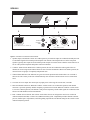
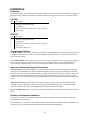
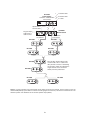
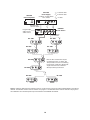
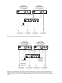
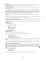
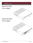
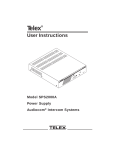
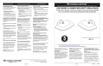
User Instructions
1
00
-2
PS
1
2
™
Model PS-2001L
Power Supply
1
0
20
S-
SP
1
2
™
Model SPS-2001
Power Supply
Audiocom® Intercom Systems
9350-7699-000 Rev. A, 4/2001
1
l
Vo
um
e
L
FCC Statement
This equipment uses, and can radiate radio frequency energy that may cause interference to radio
communications if not installed in accordance with this manual. The equipment has been tested
and found to comply with the limits of a Class A computing device pursuant to Subpart J, Part 15
of FCC Rules which are designed to provide reasonable protection against such interference
when operated in a commercial environment. Operation of this equipment in a residential area
may cause interference which the user (at his own expense) will be required to correct.
This product meets Electromagnetic Compatibility Directive 89/336/EEC
2
Table of Contents
Description ................................................................................ 4
PS-2001L........................................................................................................................................ 4
SPS-2001 ........................................................................................................................................ 5
Installation ................................................................................. 6
Unpacking ..................................................................................................................................... 6
PS-2001L........................................................................................................................................ 6
SPS-2001 ........................................................................................................................................ 6
Configuration Switches ................................................................................................................ 6
Intercom Channel and Program Connections ........................................................................... 6
Desktop or Rackmount Installation ............................................................................................ 6
Specifications ........................................................................... 12
General ........................................................................................................................................ 12
Intercom Channels ..................................................................................................................... 12
General ........................................................................................................................................ 12
Balanced Mode (set to BAL position) ....................................................................................... 12
Unbalanced Mode (set to UNBAL position) ............................................................................. 12
Speaker Inputs (SPS-2001 Only) ............................................................................................... 12
Approvals .................................................................................................................................... 12
Power-Up Check ..................................................................... 12
3
Description
The PS-2001L and SPS-2001 are versatile power supplies that can be used in a variety of Audiocom® intercom
system applications. They both directly accept any AC input power from 100 to 240 VAC, 50/60 Hz and can be
configured to power two separate intercom channels or one large intercom channel with twice the intercom station
capacity. Additionally, the units can be configured for compatibility with Clear-Com* Intercom Systems. The units
may be rack mounted or used on a desktop. For rack mounting, optional hardware is required. For desktop use, four
non-marring rubber feet are supplied. The SPS-2001 also provides a speaker with two mixed inputs making it ideal
for situations calling for a master station with a microphone / speaker combination.
PS-2001L
PS-2001L
®
1
Combine
Isolate
2
1
3
4
CH 1
100-240 VAC 60/50 HZ
TELEX COMMUNICATIONS, INC. MADE IN USA
2
CH 2
UNBAL
BAL
CLASS 2 WIRING 1.5A 24VDC
5
Figure 1 - PS-2001L Front and Rear Panel Features.
1. Combine / Isolate Switch: When in the Combine position, the unit will combine the audio signals of the two
channels to create a single audio channel where all users can intercommunicate. When in the Isolate position, the
unit will create two groups of completely independent users.
2. Channel Status Indicators: The indicators are green for normal operation and red when there is an overload or
short circuit. The circuitry in the unit will automatically reset when the overload or short circuit is located and
fixed.
3. Universal AC Power Input: The unit accepts any input power in the range of 100-240 VAC, 50/60 Hz.
4. Intercom Channel Connectors: When the Combine / Isolate switch is set to the Isolate position, each channel
connector is powered separately and has completely separate intercom audio. When the Combine / Isolate switch
is set to the Combine position, each channel is still powered separately, but the audio signals are combined so that
all users on both channels can intercommunicate.
5. BAL / UNBAL Selector Switch: This selector switch allows the user to configure the unit for use in either an
Audiocom® (BALANCED) or Clear-Com (UNBALANCED) system. Compatibility includes channel connector
pin-outs, channel power requirements, and call signaling requirements. The default setting for this switch is in the
Audiocom® (BAL) position.
4
SPS-2001
SPS-2001
®
1
Combine
Isolate
2
Volume
1
3
2
4
5
CH 1
INPUT 1
CH 2
SPEAKERS
LINE LEVEL
1VRMS
100-240 VAC 60/50 HZ
TELEX COMMUNICATIONS, INC. MADE IN USA
INPUT 2
UNBAL
BAL
CLASS 2 WIRING 1.5A 24VDC
6
Figure 2 - SPS-2001 Front and Rear Panel Features.
1. Speaker, Inputs, and Volume Control: Two audio inputs are provided. The inputs are combined internally and sent
as a monaural signal to the internal speaker amplifier. The Volume control adjusts the level to the front panel
speaker. Typically, these inputs are used with the speaker outputs of a master station when the master station is set
for use with a panel microphone and speaker instead of a headset.
2. Combine / Isolate Switch: When in the Combine position, the unit will combine the audio signals of the two
channels to create a single audio channel where all users can intercommunicate. When in the Isolate position, the
unit will create two groups of completely independent users.
3. Channel Status Indicators: The indicators are green for normal operation and red when there is an overload or
short circuit. The circuitry in the unit will automatically reset when the overload or short circuit is located and
fixed.
4. Universal AC Power Input: The unit accepts any input power in the range of 100-240 VAC, 50/60 Hz.
5. Intercom Channel Connectors: When the Combine / Isolate switch is set to the Isolate position, each channel
connector is powered separately and has completely separate intercom audio. When the Combine / Isolate switch
is set to the Combine position, each channel is still powered separately, but the audio signals are combined so that
all users on both channels can intercommunicate.
6. BAL / UNBAL Selector Switch: This selector switch allows the user to configure the unit for use in either an
Audiocom® (BALANCED) or Clear-Com (UNBALANCED) system. Compatibility includes channel connector
pin-outs, channel power requirements, and call signaling requirements. The default setting for this switch is in the
Audiocom® (BAL) position.
5
Installation
Unpacking
The package contains the following items. Contact the shipper or your Audiocom® dealer immediately if anything is
damaged or missing. Detach and fill out the registration card and return it to Telex to properly register the product.
PS-2001L
Qty
1
1
1
4
1
Description
PS-2001L Power Supply
Warranty and registration card
User Manual
Rubber Feet (install for desktop use of the PS-2001L)
Power Cord
SPS-2001
Qty
1
1
1
4
1
1
Description
PS-2001L Power Supply
Warranty and registration card
User Manual
Rubber Feet (install for desktop use of the PS-2001L)
Power Cord
RCA to RCA Patch Cord
Configuration Switches
The BAL / UNBAL switch (located on the rear of the unit) is set to the Balanced (Audiocom) position when the unit
is shipped from the factory. To set the switch to the Unbalanced (Clear-Com) mode, use a pointed object such as a
pen to push in the switch.
The Combine / Isolate switch (located on the front of the unit) can be changed at any time by using a pointed object
such as a pen to push in the switch. When the switch is in the Combine position, all users on both channels may
intercommunicate. When the switch is set to the Isolate position, channels 1 and 2 cannot intercommunicate.
Intercom Channel and Program Connections
Channel Capacity: When connecting intercom stations to the PS-2001L or SPS-2001, determine the total current
for all stations on each channel. The total per channel should not exceed 2A. If you exceed this limit, an overload
indication will be provided and the output of the power supply will be turned off. Once the overload is corrected, the
overload indication will disappear and the power supply output will be turned on. Note that if you are using DC
wallpacks with some intercom stations, you do not need to add the current consumption of those stations to the total
current.
Audiocom Connections: Intercom Cable wiring details are shown in Figure 3. Speaker interconnection cables
(SPS-2001 only) are standard RCA phono types. For program input cable wiring, refer to your master intercom
station user manual. Some typical intercom applications are shown in Figures 4 through 8.
Clear-Com Applications: Refer to your Clear-Com system documentation for intercom cable wiring and connection
details.
Desktop or Rackmount Installation
For desktop use, install the four supplied rubber feet to the bottom of the unit. Do not obstruct the cooling vents
when using the unit on a desktop.
For rackmounting, use an optional Audiocom Rackmount Kit. Several kits are available to meet the requirements of
your particular system. Follow the assembly instructions supplied with the rackmount kit.
6
TYPICAL 1-CHANNEL CABLE WIRING
3
2
Pair 1
3
2
1
Pair 2
1 (Both wires)
Shield
Shield
Cable Type: 22AWG Stranded, 2-Pair Twisted-wire, with Shield
Connector Type: 3-Pin XLR Audio (Neutrik or Switchcraft)*
Pin 1: Common
Denotes twisted pair.
Pin 2: Channel Audio / Power
Pin 3: Channel Audio / Power
Denotes shield.
Shield: Earth ground
TYPICAL 2-CHANNEL CABLE WIRING
4
3
6
5
4
3
6
5
Pair 1
Pair 2
1
1 (Both wires)
Pair 3
Shield
Shield
Cable Type: 22AWG Stranded, 3-Pair Twisted-wire, with Shield
Connector Type: 6-Pin XLR Audio (Neutrik only, not compatible with 6-pin Switchcraft)*
Pin 1: Channel 1 & 2 Common
Pin 2: No connection
Denotes twisted pair.
Pin 3: Channel 1 Audio / Power
Pin 4: Channel 1 Audio / Power
Denotes shield.
Pin 5: Channel 2 Audio / Power
Pin 6: Channel 2 Audio / Power
Shield: Earth ground
3
Ch1 2
1
Case
“Y” CABLE WIRING
Pair 1
Pair 2
3
Ch2 2
1
Shield
Pair 3
4
3
6
5
1 (Both wires)
Shield
Use second drain wire if available, or add an extra section of wire.
*
Standard cables are generally constructed using a male connector at one end and a
female connector at the other end. This allows several cables to be interconnected to
create longer cable runs. Audiocom master stations, speaker stations and belt packs
also typically provide both a male and female Neutrik connector for each intercom
channel. This permits loop-through connection of several intercom stations using the
standard cables. Audiocom power supplies use a 3-pin male Neutrik connector for
each channel. Audiocom wallplates use male Neutrik connectors.
Figure 3 - Cable Wiring Diagrams for Audiocom Applications.
7
1
PS-2001L
Power Supply
2
Combine / Isolate Switch
Y
set to Isolate
1-channel cable
2-channel cable
“Y” cable
CH 2
CH 1
100-240 VAC 60/50 HZ
TELEX COMMUNICATIONS, INC.
MADE IN USA
BAL
UNBAL
CLASS 2 WIRING 1.5A 24VDC
1
1
PUSH
US2000A
Master Station
PUSH
PROGRAM
INPUTS
+
SPEAKERS
LINE LEVEL
1 VRMS
-
1
VOL
PGM 1
VOL
PGM 2
2
P.A.
12-15 VDC
BAL - OUT
UNBAL - IN
CHN 2
CHN 1
To all stations
on channel 1
1
BP-1000
HEADSET
To all stations
on channel 2
1
BP-1000
LINES
HEADSET
1
BP-1000
HEADSET
EXP
OUT
1
BP-1000
LINES
HEADSET
LINES
LINES
Y
BP-2000
HEADSET
Note: A JB-2 Junction Box may be
used instead of the “Y” cables. The
JB-2 provides a means of combining
two channels, while also allowing the
single channels to be continued
directly from the junction box.
LINES
2
BP-2000
HEADSET
LINES
Y
BP-1000
HEADSET
BP-1000
LINES
HEADSET
LINES
Figure 4 - Typical connections using a single PS-2001L Power Supply to power two channels.
8
1
SPS-2001
Power Supply
2
Combine / Isolate Switch
Y
set to Isolate
1-channel cable
2-channel cable
“Y” cable
CH 2
CH 1
SPEAKER
INPUT 1
INPUT 2
100-240 VAC 60/50 HZ
TELEX COMMUNICATIONS, INC.
MADE IN USA
Speaker Interconnect cable.
Program Input
cable. From 2
audio sources
UNBAL
CLASS 2 WIRING 1.5A 24VDC
1
1
PUSH
US2000A
Master Station
PUSH
PROGRAM
INPUTS
+
SPEAKERS
LINE LEVEL
1 VRMS
-
1
VOL
PGM 1
VOL
PGM 2
2
P.A.
12-15 VDC
EXP
OUT
BAL - OUT
UNBAL - IN
HEADSET
To all stations
on channel 2
1
BP-1000
LINES
HEADSET
1
BP-1000
CHN 2
CHN 1
To all stations
on channel 1
1
BP-1000
HEADSET
BAL
LINE LEVEL
1 VRMS
1
BP-1000
LINES
HEADSET
LINES
LINES
Y
BP-2000
HEADSET
Note: A JB-2 Junction Box may be
used instead of the “Y” cables. The
JB-2 provides a means of combining
two channels, while also allowing the
single channels to be continued
directly from the junction box.
LINES
2
BP-2000
HEADSET
LINES
Y
BP-1000
HEADSET
BP-1000
LINES
HEADSET
LINES
Figure 5 - Typical connections using one SPS-2001 Power Supply for two intercom channels. The two program sources are
monitored independently by their intercom channels. All audio (program and intercom) is monitored as a monaural mix in the
SPS-2001 speaker. The US2000A is set for monaural speaker output (default).
9
1
SPS-2001
Power Supply
2
Combine / Isolate Switch
Y
set to Isolate
SPK1000
Powered Speaker
TELEX COMMUNICATIONS, INC.
MADE IN USA
1-channel cable
2-channel cable
“Y” cable
CH 2
CH 1
SPEAKER
INPUT 1
INPUT 1
+
INPUT 2
INPUT 2
100-240 VAC 60/50 HZ
BAL
LINE LEVEL
1 VRMS
12-15 VDC
TELEX COMMUNICATIONS, INC.
MADE IN USA
Speaker interconnect cables.
Program input
cable. From 2
audio sources
UNBAL
CLASS 2 WIRING 1.5A 24VDC
1
1
PUSH
US2000A
Master Station
PUSH
PROGRAM
INPUTS
+
SPEAKERS
LINE LEVEL
1 VRMS
-
1
VOL
PGM 1
VOL
PGM 2
2
P.A.
12-15 VDC
EXP
OUT
BAL - OUT
UNBAL - IN
HEADSET
To all stations
on channel 2
1
BP-1000
LINES
HEADSET
1
BP-1000
CHN 2
CHN 1
To all stations
on channel 1
1
BP-1000
HEADSET
BAL
LINE LEVEL
1 VRMS
1
BP-1000
LINES
HEADSET
LINES
LINES
Y
BP-2000
HEADSET
Note: A JB-2 Junction Box may be
used instead of the “Y” cables. The
JB-2 provides a means of combining
two channels, while also allowing the
single channels to be continued
directly from the junction box.
LINES
2
BP-2000
HEADSET
LINES
Y
BP-1000
HEADSET
BP-1000
LINES
HEADSET
LINES
Figure 6 - Adding an SPK1000 to the example in Figure 5. The two program sources are monitored independently by the intercom
channels. The SPS-2001 monitors intercom channel 1 and program 1. The SPK1000 monitors intercom channel 2 and program 2.
The US2000A is set for binaural speaker output as described in the US2000A User Manual.
10
PS-2001L
Channel 1 Power
Combine / Isolate Switch
set to Combine
PS-2001L
Channel 2 Power
Combine / Isolate Switch
set to Combine
CH 2
CH 1
100-240 VAC 60/50 HZ
TELEX COMMUNICATIONS, INC.
CH 2
CH 1
100-240 VAC 60/50 HZ
MADE IN USA
TELEX COMMUNICATIONS, INC.
BAL
UNBAL
MADE IN USA
BAL
UNBAL
CLASS 2 WIRING 1.5A 24VDC
CLASS 2 WIRING 1.5A 24VDC
1
1
PUSH
PUSH
PROGRAM
INPUTS
+
SPEAKERS
LINE LEVEL
1 VRMS
-
1
VOL
PGM 1
VOL
PGM 2
2
EXP
OUT
P.A.
12-15 VDC
BAL - OUT
UNBAL - IN
CHN 2
CHN 1
PS-L
(Optional)
1
1
To ½ of stations
on channel 1
1
To ½ of stations
on channel 1
1
To ½ of stations
on channel 2
To ½ of stations
on channel 2
Figure 7 - Using two PS-2001L Power Supplies to provide a greater capacity on each channel.
SPS-2001
Channel 1 Power
Combine / Isolate Switch
set to Combine
SPS-2001
Channel 2 Power
Combine / Isolate Switch
set to Combine
CH 2
CH 1
SPEAKER
INPUT 1
INPUT 1
INPUT 2
100-240 VAC 60/50 HZ
TELEX COMMUNICATIONS, INC.
MADE IN USA
LINE LEVEL
1 VRMS
CH 2
CH 1
SPEAKER
INPUT 2
100-240 VAC 60/50 HZ
TELEX COMMUNICATIONS, INC.
BAL
UNBAL
MADE IN USA
LINE LEVEL
1 VRMS
CLASS 2 WIRING 1.5A 24VDC
BAL
UNBAL
CLASS 2 WIRING 1.5A 24VDC
1
4
4
1
PUSH
PUSH
PROGRAM
INPUTS
+
SPEAKERS
LINE LEVEL
1 VRMS
-
1
VOL
PGM 1
VOL
PGM 2
2
P.A.
12-15 VDC
EXP
OUT
BAL - OUT
UNBAL - IN
CHN 2
CHN 1
US2000A
Internal DIP
switches set
for binaural
operation
PS-L
(Optional)
1
Program input
cable. From 2
audio sources
To ½ of stations
on channel 1
1
1
To ½ of stations
on channel 1
To ½ of stations
on channel 2
1
To ½ of stations
on channel 2
Figure 8 - Using two SPS-2001 Power Supplies to provide a greater capacity on each channel. Using two SPS-2001 Power
Supplies also lets you independently monitor and adjust volume for both intercom channels without the need for a separate
powered loudspeaker. In this application, the US2000A should be set for binaural speaker output as described int he US2000A
manual.
11
Power-Up Check
1. Plug in any DC wallpacks that are being used with individual intercom stations. Note: If you plug in DC
wallpacks after applying power to the PS-2001L or SPS-2001, you may get an overload indication. This is
because the stations that are being powered by wallpacks will draw current from the units until their own DC
wallpack supplies are connected. To correct the problem, plug in the DC wallpacks.
2. Plug in the AC power cords for any connected PS-2001L or SPS-2001 Power Supplies. The channel status
indicators should be green.
3. If a channel status indicator turns red during operation, locate the short or overload that is causing the problem.
Once the short or overload is corrected, the Power Supply should reset itself and the overload indication should
go away.
Specifications
General
Input Power Requirements: 100 to 240 VAC, 50/60 Hz
Output Power (each channel): 21±1 VDC, 2 A
Dimensions 1.75”(44.5 mm) high x 8.25” (209.5 mm) wide x 10.31” (261.9 mm) deep
Weight: approximately 2.5 lb (1.13 kg)
Environmental Requirements:
Storage: -20°C to 80°C, 0% to 95% humidity, non-condensing
Operating: 0°C to 50°C, 0% to 95% humidity, non-condensing
Intercom Channels
General
Connector Type: One XLR-3M audio connector for each channel. Pin-out depends on setting of BAL / UNBAL
switch for balanced or unbalanced operation as defined below:
Balanced Mode (set to BAL position)
Line Terminating Impedance: 300 ohms ±10%
Connector Pin-out:
Pin 1
Common (audio and DC return)
Pin 2
Full-duplex, balanced intercom audio and +24 VDC output
Pin 3
Full-duplex, balanced intercom audio and +24 VDC output
Unbalanced Mode (set to UNBAL position)
Line Terminating Impedance: 150 ohms ±5%
Connector Pin-out:
Pin 1
Common (audio and DC return)
Pin 2
+24 VDC output
Pin 3
Full-duplex, unbalanced Intercom audio high
Speaker Inputs (SPS-2001 Only)
Type: RCA Phone Jack
Tip: Speaker + Input
Sleeve: Speaker - Input
Approvals
UL, CUL, CE
12
TRADEMARKS
Audiocom® is a registered trademark of Telex Communications. Names of other products mentioned herein are used for identification purposes only and may be trademarks and/or registered trademarks of their respective companies.
WARRANTY INFORMATION
Products are warranted by Telex Communications, Inc. to be free from defects in materials and workmanship for a period of one
year from the date of sale.
The sole obligation of Telex during the warranty period is to provide, without charge, parts and labor necessary to remedy covered
defects appearing in products returned prepaid to Telex. This warranty does not cover any defect, malfunction or failure caused
beyond the control of Telex, including unreasonable or negligent operation, abuse, accident, failure to follow instructions in the
manual, defective or improper associated equipment, attempts at modification and repair not authorized by Telex, and shipping
damage. Products with their serial numbers removed or effaced are not covered by this warranty.
To obtain warranty service, follow the procedures entitled “Procedure for Returns” and “ Shipping to Manufacturer for Repair or
Adjustment”.
This warranty is the sole and exclusive express warranty given with respect to Audiocom products. It is the responsibility of the user
to determine before purchase that this product is suitable for the user’s intended purpose.
ANY AND ALL IMPLIED WARRANTIES, INCLUDING THE IMPLIED WARRANTY OF MERCHANTABILITY ARE LIMITED TO THE
DURATION OF THIS EXPRESS LIMITED WARRANTY.
NEITHER TELEX NOR THE DEALER WHO SELLS TELEX PRODUCTS IS LIABLE FOR INCIDENTAL OR CONSEQUENTIAL
DAMAGES OF ANY KIND.
CUSTOMER SUPPORT
Technical questions should be directed to:
Customer Service Department
Telex
12000 Portland Avenue South
Burnsville, MN 55337 U.S.A
Telephone: (952) 884-4051
Fax: (952) 884-0043
RETURN SHIPPING INSTRUCTIONS
Procedure for Returns
If a return is necessary, contact the dealer where this unit was purchased.
If a return through the dealer is not possible, obtain a RETURN AUTHORIZATION from:
Customer Service Department
Telex Communications, Inc.
Telephone: 1-800-392-3497 or (952) 884-4051
Fax: 1-800-323-0498 or (952) 884-0043
DO NOT RETURN ANY EQUIPMENT DIRECTLY TO THE FACTORY WITHOUT FIRST OBTAINING A RETURN AUTHORIZATION.
Be prepared to provide the company name, address, phone number, a person to contact regarding the return, purchase order
number, the type and quantity of equipment, a description of the problem and the serial number(s).
Shipping to Manufacturer for Repair or Adjustment
All shipments of products should be made via United Parcel Service or the best available shipper prepaid. The equipment should
be shipped in the original packing carton; if that is not available, use any suitable container that is rigid and of adequate size. If a
substitute container is used, the equipment should be wrapped in paper and surrounded with at least four inches of excelsior or
similar shock-absorbing material. All returns must include the return authorization number. Units sent for repair or adjustment DO
NOT need a return authorization number
Factory Service department
Telex Communications, Inc.
West 1st Street
Blue Earth, MN 56013 U.S.A.
Upon completion of any repair the equipment will be returned via United Parcel Service or specified shipper collect.
13