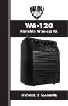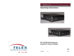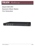
1
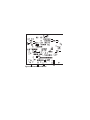
Telex
Operating Instructions
1
C
2 han
Call
Talk
BP-1002/BP-2002
Belt Packs
Audiocom® Intercom System
93507740-000 Rev E
10/2003
2
INTRODUCTION
The Audiocom® BP-1002 and BP-2002 are
microprocessor controlled one- and twochannel
intercom belt packs. An internal switch and
jumper setting allows the units to be used with
Clear-Com® components, if desired. Other
internal switch and jumper settings allow the
unit to be uniquely configured to the operator’s
requirements.
FCC STATEMENT
This equipment uses, and can radiate radio
frequency energy that may cause interference
to radio communications if not installed in
accordance with this manual. The equipment
has been tested and found to comply with the
limits of a Class A computing device pursuant
to Subpart B, Part 15 of FCC Rules which are
designed to provide reasonable protection
against such interference when operated in a
commercial environment. Operation of this
equipment in a residential area may cause
interference which the user (at his own expense) will be required to correct.
This product meets the Electromagnetic
Compatibility Directive, 89/336/EEC.
®
Audiocom is a registered trademark of Telex
Communications, Inc., Burnsville, Minnesota 55337
®
Clear-Com is a registered trademark of Clear-Com
Intercom Systems
3
End-User License Agreement for Telex® Software
IMPORTANT - Please read this document carefully before using this
product.
THIS DOCUMENT STATES THE TERMS AND CONDITIONS UPON
WHICH TELEX COMMUNICATIONS, INC. (THE ‘COMPANY’) OFFERS TO
LICENSE THE INSTALLED SOFTWARE OR PROGRAM (THE ‘SOFTWARE’) FOR USE WITH THE PRODUCT IN WHICH IT WAS INSTALLED.
YOU ARE AGREEING TO BECOME BOUND BY THE TERMS OF THIS
AGREEMENT. IF YOU DO NOT AGREE TO THE TERMS OF THIS
AGREEMENT, DO NOT USE THIS PRODUCT. PROMPTLY RETURN THE
PRODUCT TO THE PLACE WHERE YOU OBTAINED IT FOR A FULL
REFUND.
The installed software as supplied by the Company is licensed, not sold, to
you for use only under the terms of this license, and the Company reserves
all rights not expressly granted to you. You own the product or other media
on or in which the Software is originally or subsequently recorded or fixed,
but the Company retains ownership of all copies of the Software itself.
1. License: This license allows you to use the Software for internal
purposes only on a single product in which it was installed.
2. Restrictions: (a)You may not market, distribute or transfer copies of
the Software to others or electronically transfer or duplicate the
software. YOU MAY NOT REVERSE ENGINEER, DECOMPILE,
DISASSEMBLE, MODIFY, ADAPT, TRANSLATE, RENT, LEASE OR
LOAN THE SOFTWARE OR CREATE DERIVATIVE WORKS BASED
ON THE SOFTWARE OR ANY ACCOMPANYING WRITTEN
MATERIALS. (b) The Software and the accompanying written
materials are copy-righted. Unauthorized copying of the Software,
including portions thereof or the written materials, is expressly
forbidden. (c) You understand that the Company may update or revise
the Software and in so doing incurs no obligation to furnish such
updates to you.
3. Limited Warranty: The Company does not warrant that the
operation of the Software will meet your requirements or operate free
from error. The Company DISCLAIMS ALL OTHER WARRANTIES
AND CONDITIONS EITHER EXPRESS OR IMPLIED, INCLUDING
THE WARRANTIES OF MERCHANTABILITY, FITNESS FOR A
PARTICULAR PURPOSE AND NON-INFRINGEMENT OF THIRD
PARTY RIGHTS.
4. Limited Liability: The liability of the Company for any claims arising
out of this License based upon the Software, regardless of the form of
action, shall not exceed the greater of the license fee for the Software
4
OPERATION
SYSTEM POWER
The BP-2002 belt pack receives power externally, in one
of two ways:
• Via the intercom channel.
• Via the local-power (pin 2) of the intercom channel
connector
The BP-1002 belt pack receives power externally, via the
intercom channel.
Both the BP-1002 and BP-2002 will pass system power
through to subsequent belt packs that are “daisy
chained” together.
INITIAL BP-1002/BP-2002 SETUP
The channel termination is initially set for balanced
operation, which is compatible with other Audiocom®
equipment. If the unit is going to be connected to ClearCom equipment, one switch and several jumpers must
be changed as described in the section on Clear-Com
Setup in this manual.
The headset microphone type is initially set for singleended dynamic operation. To change the microphone
type to balanced dynamic, refer to Table 2 for the position
of JP9.
5
Figure 1. BP-2002 & BP-1002 Connections and Controls
6
EXTERNAL CONNECTIONS & CONTROLS
NOTE: The numbers refer to the callouts in Figure 1.
1. VOLUME CONTROL: Use this control to adjust the
headset listen level.
2.
CHAN BUTTON AND INDICATORS: The Chan button (only
on the BP-2002) allows the user to select which
intercom channel is active. The yellow indicator next
to the 1 or 2 lights to show the active channel. Press
the Chan button to change the channel selection, the
yellow indicator for that channel will light.
3. CALL BUTTON AND INDICATOR: The Call function allows the
user to send or receive signals to other devices on the
intercom channel selected. The Call button operates
in two ways:
Call receive: When there is an incoming call signal,
the indicator is red. (If Audible Call Alert is enabled,
incoming calls will cause beeps in the headset.) On
the BP-2002, calls can be received on the selected
channel only.
Call send: To send a call signal to all stations on a
channel, press and hold the Call button until a verbal
response is received. The indicator will glow red. On
the BP-2002, calls can be sent on the selected
channel only.
4. TALK BUTTON AND INDICATOR: The Talk button activates
the headset microphone and operates in two ways:
Connections and Controls
7
Latched Mode:
Tap the button once to talk. The indicator will glow
green. Tap the button again when finished with a
conversation.
Momentary Mode:
Press and hold the button to talk momentarily. Release
the button when finished talking.
NOTE:On the BP-2002, if no headset is connected
when the Talk button is pressed, the Talk button will
have the same function as the Chan button.
5. SIDETONE CONTROL: When using a headset, this control
adjusts your own voice level heard in the head
phones. To adjust the level, tap the Talk button once
to turn on the headset microphone. Then, use a small
flat-blade screwdriver to increase or decrease your
voice level while talking into themicrophone. (This
control is accessible by removing one screw of belt
clip.)
6. HEADSET CONNECTOR: This connector accepts a fourwire Telex® boom-microphone headset.
7. INTERCOM CHANNEL CONNECTORS: On the BP-2002,
intercom channels are connected via a pair of 6-pin
connectors (one male and one female). The male and
female connectors are wired together in parallel,
providing a “loop through” at each connector pin. Use
one connector to connect to the intercom channel.
Use the other connector to “daisy chain” a cable to the
next belt pack or other station on the channel.
8
Local Power Input (BP-2002 only)
Normally the BP-2002 is powered from the intercom
system and will turn on with the intercom system. The
BP-2002 belt pack may also be powered from an
optional power supply (18-30 VDC) connected between pin 2 (+) and pin 1 (-) of the intercom channel
connector.
8. INTERCOM CHANNEL CONNECTORS: On the BP-1002, the
intercom channel is connected via a pair of 3-pin
connectors (one male and one female). The male and
female connectors are wired together in parallel,
providing a “loop through” at each connector pin. Use
one connector to connect to the intercom channel.
Use the other connector to “daisy chain” a cable to the
next belt pack or other station on the channel.
OPERATING MODES
The microprocessor within the BP-1002/BP-2002
controls four modes of operation that affects the Microphone
Kill and Audible Call Alert features.
M O DE
(BEEPS)
M I C K I LL
AUDIBLE
C ALL AL ERT
1
Disabled
Disabled
2 (Default)
Enabled
Disabled
3
Disabled
Enabled
4
Enabled
Enabled
Table 1. Operating Modes
9
Changing Modes of Operation:
Perform the following steps to change the mode of operation.
1.
Both the Talk and Call indicators should be off.
2.
Press and hold the Talk key, then press and hold the
Call key, then release both keys. The Call indicator
should now glow red.
(The number of beeps heard in the headset indicates
the current mode of operation.)
3.
Press the Call key to change to the next mode of
operation. Each press of the Call key will cause the
BP-1002/BP-2002 to change to the next mode of
operation.
4.
When the desired mode is reached, press the Talk
key to select that mode and exit the mode changing
function. (Beeps will be heard in the headset when the
mode changing function is exited. The number of
beeps heard indicates the selected mode of operation.)
NOTE: Each time the intercom system power is turned on, the
beltpack will reset to the default mode of operation (Mode 2).
10
INTERNAL SWITCHES, JUMPERS AND ADJUSTMENTS
There are several internal switches, jumpers and an adjustment that affect
operation. These are described below. To gain access to the switches,
jumpers and the adjustment, disconnect all power and line connections.
Remove two screws from the top of each side and two screws from
bottom of each side. Switch, jumper and adjustment locations are shown
in Figure 2.
Figure 2. Internal Switches, Jumpers and Adjustments. Note, if you
have 9350-7749-000 board, figure 4 on page 19.
NOTE: Figure 2 shows a BP-2002 with the switches and jumpers in
their factory default positions (referenced in Table 2).
The SIDETONE adjustment is also accessible behind the screw that
holds the belt clip (callout 5 in Figure 1).
The functions of the internal switches and jumpers are described in
Table 3.
11
NOTE: On the BP-1002, jumper JP6 must always have pins 2 and 3
shorted.
Side Tone Adjustment (R145)
The side tone adjustment is accessible either internally (refer to Figure 2) or
by removing the belt clip mounting screw (callout 5 in Figure 1).
To adjust the level of your own voice heard in the headphones, tap the Talk
button once to turn on the headset microphone. Then, use a small flatblade screwdriver to increase or decrease your voice level while talking into
the microphone.
Clear-Com Setup
Make the following switch and jumper changes when the belt pack is used
with Clear-Com equipment:
BP-2002
1.
SW1 must be placed in the UNBAL position.
2.
JP4 must have pins 1 and 2 shorted (U position).
3.
JP5 jumper must be removed and placed on JP2.
4.
JP2 must have pins 1 and 2 shorted (using jumper from JP5).
5.
JP1 must have pins 1 and 2 shorted.
BP-1002
1.
SW1 must be placed in the UNBAL position.
2.
JP4 must have pins 1 and 2 shorted (U position).
3.
JP6, JP5 must have pins 2 and 3 shorted at all times.
Pr o d u c t
BP-1002
Def au l t J u m p er Set t i n g s
Shor ting across Pins 1 and 2:
JP13
Shor ting across Pins 2 and 3:
JP5, JP6 and JP9
Not Populated:
JP1, JP2, and JP3
Populated on Pin 1 Only:
JP4
BP-2002
Shor ting across Pins 1 and 2:
JP9 and JP13
Shor ting across Pins 2 and 3:
JP5 and JP6
Not Populated:
JP3
Populated on Pin 1 Only:
JP1, JP2, and JP4
Table 2. Default Settings. If you are using the 000 board, see page 19 for the
default settings.
12
Table 3. Internal Switches and Jumpers
Jumper/Switch
Number
Jumper or Switch Function
Default Setting
SW3
^
Electret/Dynamic Microphone
Select
(Must be set to Dynamic when JP9
functions are designed
Dynamic
JP9
^
^
Balanced/Single-ended Dynamic
Pins 1&2
shor ted
Mic
(SW1 must be set to Dynamic)
Single-ended Mic: Pins 1&2 shor ted
^
Balanced Mic: Pins 2&3 shor ted
JP6
^
^
Power Select
Channel One Power : Pins 2&3
shor ted
(On BP-1002, pins 2&3 always
shor ted)
^
Channel Two Power : Pins 1&2
shor ted
JP5
Power Select
^
Channel One Power : Pins 2&3
shor ted (On BP-1002, Pins 2&3
always shor ted.)
Channel Two Power : Pins 1&2
Shor ted
^
^
^
Pins 2&3
shor ted
Pins 2&3
shor ted
(Must be set for same channel as
JP6 for proper power operation in
Audiocom® mode on BP-2002)
(Must be used in conjunction with
SW1)
SW1
Clear-Com / Audiocom® Operation
^
^
Unbalanced / Balanced Line
(Must be used in conjunction with
JP4, JP5, JP2, and JP1)
JP4
Clear-Com / Audiocom® Operation
Pins 1&2 shor ted: UNBAL (ClearCom)
Jumper on one
pin only
JP2
No jumper
present
Balanced
^
DC Call Detect (Clear-Com
operation only, not used in
Audiocom® mode) BP-2002 only
Disabled: No pins jumpered
^
^
Enabled: Pins 1&2 shor ted
(To enable, use jumper from JP5)
JP1
Jumper on one
pin only
^
^
DC Call Detect (Clear-Com
operation only, not used in
Audiocom® mode) BP-2002 only
Disabled: No pins jumpered
Enabled: Pins 1&2 shor ted
JP13
For RTS™ use only
Must be
installed
13
Note: In case of local power use, install a jumper on pins
2 & 3 of U6
CONNECTOR PIN CONFIGURATIONS
Headset Connector
Type: XLR-4M (callout 6 in Figure 1)
Pin 1
Headset microphone low
Pin 2
Headset microphone high
Pin 3
Headphone high
Pin 4
Headphone low
Intercom Channel Connectors
BP-1002
Type: One XLR-3M and XLR-3F pair (callout 8 in Figure 1)
Audiocom® Mode (Internal switch SW1 and jumpers JP4, JP5, JP2 and JP1
set to BAL position)
Pin 1
Common
Pin 2
Intercom audio low and +24 VDC input
Pin 3
Intercom audio high and +24 VDC input
Clear-Com Mode (Internal switch SW1 and jumpers JP4, JP5, JP2 and JP1
set to UNBAL position)
Pin 1
Common
Pin 2
+30 VDC input
Pin 3
Intercom audio/call signal
14
BP-2002
Type: One XLR-6M and XLR-6F pair (callout 7 in Figure 1)
Audiocom® Mode (Internal switch SW1 and jumpers JP4, JP5, JP2 and
JP1 set to BAL position)
Pin 1
Pin 2
Pin 3
Pin 4
Pin 5
Pin 6
Common
Local power (+24 VDC)
Channel A intercom audio low and +24 VDC input
Channel A intercom audio high and +24 VDC input
Channel B intercom audio low and +24 VDC input
Channel B intercom audio high and +24 VDC input
Clear-Com Mode (Internal switch SW1 and jumpers JP4, JP5, JP2 and
JP1 set to UNBAL position)
Pin 1
Pin 2
Pin 3
Pin 4
Pin 5
Pin 6
Common
Local power (14 to 30 VDC)
Channel A +30 VDC input
Channel A intercom audio/call signal
Channel B +30 VDC input
Channel B intercom audio/call signal
15
SPECIFICATIONS
GENERAL:
Power Requirements:
Channel supplied: 24 VDC nominal, 45 to 70 mA
Local-power: (BP-2000 only) 24 VDC nominal (18 to 30
VDC), 45 to 70 mA
Environmental Requirements:
Storage:
-20ºC to 80ºC; 0% to 95% humidity,
non-condensing
Operating: -15ºC to 60ºC; 0% to 95% humidity,
non-condensing
Dimensions: 5.0" (127 mm) H x 3.5" (88.9 mm) W x 1.8"
(45.7 mm) D
Weight: 1.5 pounds (0.68 kg)
INTERFACE REQUIREMENTS:
Headset:
50 to 200 ohm dynamic microphone
150 to 600 ohm headphones
Balanced Intercom Channel:
Output Level: 1 Vrms nominal
Input Impedance: 300 ohm ±5%
Bridging Impedance: greater than 10,000 ohm
Call Signalling:
Send: 20 kHz ±100 Hz, 0.5 Vrms ±10%
Receive: 20 kHz ±800 Hz, 100 mVrms
Mic-Off Frequency:
Detect: 24 kHz ±800 Hz, 100 mVrms
Noise Contribution: less than -60 dB on the line
16
Unbalanced Intercom Channel:
Output Level: 480 mVrms ±10%
Input Impedance: 200 ohm ±5%
Bridging Impedance: greater than 10,000 ohm
Call Signalling:
Send: 12 ±3 VDC
Receive: 4 VDC minimum
HEADPHONE AMPLIFIER:
Voltage Gain:
20 ±3 dB from the line
Maximum Output:
60 mW into 150 ohm
Frequency Response:
200 Hz to 8 kHz with no more than 4 dB deviation
Audible Alert:
1 kHz, at the headset
Total Harmonic Distortion:
Less than 2% at 50 mW from the line
Sidetone:
20 dB minimum range, adjustable
17
DYNAMIC MICROPHONE AMPLIFIER:
Voltage Gain:
Mic to Channel; 45 ±3 dB, before limiting
Mic to Headphone; adjustable, 65 dB range into 150
ohm
Frequency Response:
200 Hz to 8 kHz +1/-3dB
Total Harmonic Distortion:
Less than 1% at Channel output at 1 kHz
ELECTRET MICROPHONE AMPLIFIER:
Voltage Gain:
Mic to Channel; 24 ±3 dB, before limiting
Mic to Headphone; adjustable, 45 dB ±10% into
150ohm
Frequency Response:
200 Hz to 8 kHz +1/-3dB
Total Harmonic Distortion:
Less than 1% at Channel output
18
Figure 4. Board Number 9040-7740-000.
Product
Default Jumper Settings
BP-1002
Shor ting across Pins 1 and 2:
JP7, JP8, JP10, JP11, JP12,
and JP13
Shor ting across Pins 2 and 3:
JP5, JP6 and JP9
Not Populated:
JP1, JP2, and JP3
Populated on Pin 1 Only:
JP4
BP-2002
Shor ting across Pins 1 and 2:
JP7, JP8, JP9, JP10, JP11,
JP12, and JP13
Shor ting across Pins 2 and 3:
JP5 and JP6
Not Populated:
JP3
Populated on Pin 1 Only:
JP1, JP2, and JP4
Default Settings
19
APPENDIX A
OPTIONAL FOOTBALL MODIFICATIONS
GENERAL DESCRIPTION
In Audiocom® Intercom Systems, the Mic-Kill feature is used to turn off any
activated microphones on a selected channel. The Mic-Kill feature is
activated when the beltpack receives a 24 kHz signal from the channel. In
some applications the Mic-Kill and Call signal features are not desired and
need to be disabled.
ELIMINATING MIC-KILL AND CALL SIGNAL
CAUTION
TO PREVENT DAMAGE TO THE EQUIPMENT, THESE MODIFICATIONS
SHOULD ONLY BE MADE BY QUALIFIED TECHNICIANS.
If desired, the Mic-Kill and Call signal features can be disabled in the BP2002/BP-1002 by removing a surface-mounted capacitor from the printed
circuit board. Perform the following:
1.
Before making changes to the printed circuit board,
disconnect all power and line connections from the beltpack.
2.
Refer to Figure 3 and locate C61 on the underside of
the printed circuit board.
3.
Remove capacitor C61 from the printed circuit board.
RESTORING MIC-KILL AND CALL SIGNAL
To restore the Mic-Kill and Call signal features, replace C61 with Telex® part
number 102879-218, 1500 pF, 50V capacitor.
20
Figure 3. Printed Circuit Board
FACTORY SERVICE
All equipment returned for repair must be accompanied by documentation
stating your return address, telephone number and proof of date of
purchase, along with a description of the problem. In lieu of this, you may
obtain a Return Authorization form from our Customer Service Department.
Customer Service Department
Telex Communications, Inc.
12000 Portland Avenue South
Burnsville, Minnesota 55337 U.S.A.
Telephone: (800) 392-3497
Fax: (800) 323-0498
Return equipment to:
Service Department
Telex Communications, Inc.
West 1st Street
Blue Earth, Minnesota 56013 U.S.A.
WARRANTY REPAIRS - If in warranty, no charge will be made for the repairs.
Equipment being returned for warranty repair must be sent prepaid and will
be returned prepaid.
NON-WARRANTY REPAIRS - Equipment that is not under warranty must be sent
prepaid to Telex. If requested, an estimate of repair costs will be issued
prior to service. Once your approval for repair, and repair of equipment is
completed, the equipment will be returned on a collect basis. Collect
charges may be avoided by sending a signed check for payment in full
along with your signed estimate approval form (the estimate includes the
shipping charge).
22