1
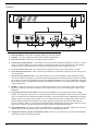
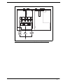
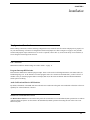
Model EMS-4001
Expansion Master Station
User Instructions
9350-7713-000 Rev E
1/2010
PROPRIETARY NOTICE
The product information and design disclosed herein were
originated by and are the property of Bosch Security Systems, Inc.
Bosch reserves all patent, proprietary design, manufacturing,
reproduction, use and sales rights thereto, and to any article
disclosed therein, except to the extent rights are expressly granted
to others.
COPYRIGHT NOTICE
in a residential area may cause interference which the user (at his
own expense) will be required to correct.
This package should include:
QTY
DESCRIPTION
PART NO.
90107713000 (US)
1
EMS4000 Final Assembly
or
90107713001 (EU)
Copyright 2010 by Bosch Security Systems, Inc. All rights
reserved. Reproduction, in whole or in part, without prior written
permission from Bosch is prohibited.
2
Power Cord
2504000300
3
User Manual
93507713000
WARRANTY NOTICE
4
Warranty Card
38110390
5
User Information
38110668
6
Statement of Conformity
38110675
7
Int’l Cordsets, European
model only
550024000
See the enclosed warranty card for further details.
CUSTOMER SUPPORT
Technical questions should be directed to:
Customer Service Department
Bosch Security Systems, Inc.
12000 Portland Avenue South
Burnsville, MN 55337 USA
Telephone: 800-392-3497
Fax: 800-323-0498
RETURN SHIPPING INSTRUCTIONS
Customer Service Department
Bosch Security Systems, Inc. (Lincoln, NE)
Telephone: 402-467-5321
Fax: 402-467-3279
Factory Service: 800-553-5992
Please include a note in the box which supplies the company name,
address, phone number, a person to contact regarding the repair, the
type and quantity of equipment, a description of the problem and
the serial number(s).
SHIPPING TO THE MANUFACTURER
All shipments of product should be made via UPS Ground, prepaid
(you may request from Factory Service a different shipment
method). Any shipment upgrades will be paid by the customer. The
equipment should be shipped in the original packing carton. If the
original carton is not available, use any suitable container that is
rigid and of adequate size. If a substitute container is used, the
equipment should be wrapped in paper and surrounded with at least
four (4) inches of excelsior or similar shock-absorbing material. All
shipments must be sent to the following address and must include
the Proof of Purchase for warranty repair. Upon completion of any
repair the equipment will be returned via United Parcel Service or
specified shipper, collect.
Factory Service Department
Bosch Security Systems, Inc.
8601 East Cornhusker Hwy.
Lincoln, NE 68507 U.S.A.
Attn: Service
FCC STATEMENT
This equipment uses, and can radiate radio frequency energy that
may cause interference to radio communications if not installed in
accordance with this manual. The equipment has been tested and
found to comply with the limits of a Class A computing device
pursuant to Subpart J, Part 15 of FCC Rules which are designed to
provide reasonable protection against such interference when
operated in a commercial environment. Operation of this equipment
THE LIGHTNING
FLASH AND
ARROWHEAD
WITHIN THE
TRIANGLE IS A
WARNING SIGN
ALERTING YOU OF
“DANGEROUS
VOLTAGE” INSIDE
THE PRODUCT.
CAUTION: TO REDUCE THE
RISK OF ELECTRIC SHOCK,
DO NOT REMOVE COVER.
NO USER-SERVICABLE
PARTS INSIDE. REFER
SERVICING TO QUALIFIED
SERVICE PERSONNEL.
THE
EXCLAMATION
POINT WITHIN
THE TRIANGLE IS
A WARNING SIGN
ALERTING YOU
OF IMPORTANT
INSTRUCTIONS
ACCOMPANYING
THE PRODUCT
SEE MARKING ON BOTTOM/BACK OF PRODUCT
WARNING: APPARATUS SHALL NOT BE EXPOSED TO DRIPPING OR
SPLASHING AND NO OBJECTS FILLED WITH LIQUIDS, SUCH AS VASES,
SHALL BE PLACED ON THE APPARATUS.
WARNING: THE MAIN POWER PLUG MUST REMAIN READILY OPERABLE.
CAUTION: TO REDUCE THE RISK OF ELECTRIC SHOCK, GROUNDING OF
THE CENTER PIN OF THIS PLUG MUST BE MAINTAINED.
WARNING: TO REDUCE THE RISK OF FIRE OR ELECTRIC SHOCK, DO NOT
EXPOSE THIS APPRATUS TO RAIN OR MOISTURE.
WARNING: TO PREVENT INJURY, THIS APPARATUS MUST BE SECURELY
ATTACHED TO THE FLOOR/WALL/RACK IN ACCORDANCE WITH THE
INSTALLATION INSTRUCTIONS.
This product is AC only.
Important Safety Instructions
1.
Read these instructions.
2.
Keep these instructions.
3.
Heed all warnings.
4.
Follow all instructions.
5.
Do not use this apparatus near water.
6.
Clean only with dry cloth.
7.
Do not block any ventilation openings. Install in accordance with the
manufacturer’s instructions.
8.
Do not install near any heat sources such as radiators, heat registers, stoves, or
other apparatus (including amplifiers) that produce heat.
9.
Do not defeat the safety purpose of the polarized or grounding-type plug. A
polarized plug has two blades with one wider than the other. A grounding type
plug has two blades and a third grounding prong. The wide blade or the third
prong are provided for your safety. If the provided plug does not fit into your
outlet, consult an electrician for replacement of the obsolete outlet.
10. Protect the power cord from being walked on or pinched particularly at plugs,
convenience receptacles, and the point where they exit from the apparatus.
11. Only use attachments/accessories specified by the manufacturer.
12. Use only with the cart, stand, tripod, bracket, or table specified by the
manufacturer, or sold with the apparatus. When a cart is used, use caution
when moving the cart/apparatus combination to avoid injury from tip-over.
13. Unplug this apparatus during lightning storms or when unused for long
periods of time.
14. Refer all servicing to qualified service personnel. Servicing is required when
the apparatus has been damaged in any way, such as power-supply cord or
plug is damaged, liquid has been spilled or objects have fallen into the
apparatus, the apparatus has been exposed to rain or moisture, does not
operate normally, or has been dropped.
Table
of
Contents
IMPORTANT SAFETY INSTRUCTIONS ..................................................................................................................................... 3
INTRODUCTION ....................................................................................................................................7
Description .......................................................................................................................................................... 7
Features .............................................................................................................................................................. 8
INSTALLATION ...................................................................................................................................11
Configuration Pre-check ................................................................................................................................... 11
DIP Switches ..................................................................................................................................................... 11
PROGRAM INTERRUPT DIP SWITCHES .............................................................................................................................. 11
AUDIO CALL SEND AND RECEIVE DIP SWITCHES ............................................................................................................. 11
Balanced/Unbalanced Switch ........................................................................................................................... 11
Direct Program Listen Enable/Disable Jumpers .............................................................................................. 12
Sidetone Trimmers ............................................................................................................................................ 12
Mounting Configurations .................................................................................................................................. 14
Connection Notes .............................................................................................................................................. 14
Cables ............................................................................................................................................................... 15
OPERATION .........................................................................................................................................17
Power-Up .......................................................................................................................................................... 17
Sidetone Adjustments ........................................................................................................................................ 17
Operation .......................................................................................................................................................... 18
Specifications .................................................................................................................................................... 19
CHAPTER 1
Introduction
Description
The EMS-4001 adds four (4) powered intercom channels to an MS-2001 Master Station, and it provides talk, listen and call
buttons for the added channels. Up to four (4) EMS-4001 Expansion Master Stations may be connected to the MS-2001
allowing up to 16 channels (18 channels total). The MS-2001 microphone is used to talk back to the EMS-4001 channels, and
the MS-2001 speaker is typically used for listening. However, there are also separate speaker jacks on the back panel of the
EMS-4001 for independent monitor speakers, if desired. There are also four (4) additional program inputs on the back of the
EMS-4001, one (1) for each added channel.
The MS-2001/ EMS-4001 combination can be used as a simple, multi-channel intercom user stations. In this configuration, the
program inputs (and possibly the PA output of the MS-2001) are most likely not used, and the station operator has only talk,
listen and call capability. It is also possible the advanced features of the MS-2001, such as Mic Kill Send, might be turned off.
Alternatively, the MS2001/ EMS-4001 can be used as a master station. In this application, one (1) or more program inputs and
the PA output may be connected, and the program signals to the intercom channels can be turned on or off from the MS-2001.
Additionally, the Mic Kill Send feature can be enabled, and microphones on any channels may then be turned off from the
MS-2001.
7
Features
FIGURE 1.
8
EMS-4001 Front and back features
1.
Intercom Talk Keys - Momentary or latching (hands-free operation possible).
2.
Call Keys - Used to call intercom channels and to indicate incoming calls.
3.
Intercom Listen Keys - Momentary or latching operation possible.
4.
Channel Power Status Indicators - The indicators are green for normal operation and change to red if there is a short
circuit or overload condition on a power output line. If an indicator turns red, either disconnect the corresponding
channel connector or turn off the intercom system and locate the problem before resuming operation.
5.
Universal AC Power Connector - The unit accepts any input power in the range of 100-240VAC, 50/60Hz.
6.
Intercom Channel Connectors - These connectors provide the power and audio connections for each of the four (4)
intercom channels.
7.
EXP IN and EXP OUT Connectors - The EXP IN connector receives the microphone audio signal from the MS2001, and it sends the monaural mix of the four (4) EMS-4001 channels to the MS-2001 speaker or headset. The EXP
OUT connector connects to the EXP IN connector of an additional EMS-4001. Up to four (4) EMS-4001 Expansion
Master Stations may be daisy chained with the EXP IN and EXP OUT connectors. An EXP IN/OUT cable is supplied
with each EMS-4001.
8.
Speakers - Usually, the listen mix of all four (4) EMS-4001 channels is sent to the MS-2001 speaker or headset via
the EXP IN connector. Alternatively, speakers may be connected to one (1) or more of the speaker outputs of the
EMS-4001.
9.
Program Input Connector and Trimmers - Each intercom channel has its own program input and level adjust
trimmer. For each program input, there is an internal jumper which routes the program either to the intercom channel
only, or to both the intercom channel and the MS-2001 headset or speaker (default setting). Additionally, the program
signal to the intercom channel may be turned on or off via the MS-2001 front panel programming. There is also an
internal program interrupt DIP switch that selects either automatic program interrupt when the station operator
activates a channel’s talk key, or no program interrupt during talk. The EMS-4001 program input connectors may be
broken out to common 3-pin XLR audio cables using the optional XP-4PGM Breakout Panel.
10.
BAL/UNBAL Switch - This selector switch sets the EMS-4001 for compatibility with either Audiocom or Clear-Com
channel connector pinouts, channel power requirements, and call signaling requirements.
11.
Configuration Switches, Jumpers and Sidetone Controls - These let you customize the operation of the EMS-4001
to match your intercom system requirements.
FIGURE 2.
EMS-4001 Internal DIP switches, jumpers, and adjustments
9
10
CHAPTER 2
Installation
Configuration Pre-check
Before making connections, read the following configuration notes, and make sure all switches and jumpers are properly set
for your intended usage. Locations of configuration switches and jumpers are shown in Figure 2 on page 9. Only the DIP
switches and jumpers require internal access. If access is required, remove three (3) screws from the top cover and three (3)
screws along the bottom edge from each side.
DIP Switches
DIP Switches and their default settings are listed in Table 1 on page 13.
Program Interrupt DIP Switches
Each intercom channel has a dedicated program input. These can be used to feed background music, mix-minus audio (for
broadcasting usage) etc. to the channels. If external program sources are connected to the EMS-4001, you have a choice of
whether or not you want the program audio to interrupt (shut off) on the intercom channel while the MS-2001/EM-4001
station operator is talking.
Audio Call Send and Receive DIP Switches
By default, all channels of the EMS-4001 can send and receive Audiocom call signals. You can disable call send or call receive
capability for selected channels, if desired.
Balanced/Unbalanced Switch
The BAL/UNBAL Switch is located on the back panel. The switch must be set to the balanced (BAL) position for use with an
Audiocom Intercom System. Set the switch to the unbalanced (UNBAL) position when using the unit with a Clear-Com
Intercom System.
11
Direct Program Listen Enable/Disable Jumpers
By default, each program input can be heard by intercom stations on the corresponding intercom channel. This can be turned
on or off for each program input via the MS-2002 front panel programming.
REFERENCE: See Turning the Program Inputs ON and OFF in the Operations section of the MS-2002 User Instructions
(P/N 9350-7749-000) which can be found at http://www.telexaudiocom.com/manuals.php.
Additionally, all program signals can be heard directly in the MS-2001 speaker or headset, and each program is output at the
corresponding speaker jack on the back of the EMS-4001.
To disable direct program listening for a program input, do the following:
>
Reset the appropriate jumper as shown in table 2 on page 14.
NOTE: Jumper locations are shown in figure 2 on page 9.
Sidetone Trimmers
These trimmers are normally adjusted after all components are connected, and they can be accessed through the bottom cover
as depicted in Figure 4 on page 18.
REFERENCE: See the sidetone adjustment procedure in the MS-2002 User Instructions (P/N 9350-7749-000) which can
be found at http://www.telexaudiocom.com/manuals.php.
12
TABLE 1. EMS-4001
configuration switch settings
SWITCH NUMBER
DESCRIPTION
SETTINGS
DEFAULT SETTING
DIP Switch SW1 (Internal)
SW1-1
Program Interrupt, CH6
On (Closed): Enabled
Off (Open): Disabled
Off
SW1-2
Program Interrupt, CH5
On (Closed): Enabled
Off (Open): Disabled
Off
SW1-3
Program Interrupt, CH4
On (Closed): Enabled
Off (Open): Disabled
Off
SW1-4
Program Interrupt, CH3
On (Closed): Enabled
Off (Open): Disabled
Off
SW1-5
Audio Call Send, CH3a
On (Closed): Enabled
Off (Open): Disabled
On
SW1-6
Audio Call Receive, CH3a
On (Closed): Enabled
Off (Open): Disabled
On
SW1-7
Audio Call Send, CH4a
On (Closed): Enabled
Off (Open): Disabled
On
SW1-8
Audio Call Receive, CH4a
On (Closed): Enabled
Off (Open): Disabled
On
Balanced (BAL) - Unbalanced (UNBAL) operation
Important! Both switches on the back of the unit must be set the same
SW1
Audiocom or Clear-Com
Operation
Out (Audiocom): BAL
In (Clear-Com): UNBAL
Out
SW2
Audiocom or Clear-Com
Operation
Out (Audiocom): BAL
In (Clear-Com): UNBAL
Out
DIP Switch SW3 (Internal)
SW2-1
Audiocom Call Send, CH 5a
On (Closed): Enabled
Off (Open): Disabled
On
SW2-2
Audiocom Call Receive, CH 5a
On (Closed): Enabled
Off (Open): Disabled
On
SW2-3
Audiocom Call Send, CH 6a
On (Closed): Enabled
Off (Open): Disabled
On
SW2-4
Audiocom Call Receive, CH 6a
On (Closed): Enabled
Off (Open): Disabled
On
SW2-5
Not Used
On (Closed): Enabled
Off (Open): Disabled
N/A
SW2-6
Not Used
On (Closed): Enabled
Off (Open): Disabled
N/A
SW2-7
Not Used
On (Closed): Enabled
Off (Open): Disabled
N/A
SW2-8
Not Used
On (Closed): Enabled
Off (Open): Disabled
N/A
a. These switches apply only when in Audiocom (BAL) mode. Call send and receive are always enabled in Clear-Com (UNBAL)
mode.
13
TABLE 2. EMS-4001
jumper settings
Jumper
Description
Settings for All Jumpers
J15
Program 3 direct to Headset or Speaker
Pins 2&3 Shorted: Enable
Pins 1&2 Shorted: Disable
J16
Program 4 direct to Headset or Speaker
Pins 2&3 Shorted: Enable
Pins 1&2 Shorted: Disable
J18
Program 5 direct to Headset or Speaker
Pins 2&3 Shorted: Enable
Pins 1&2 Shorted: Disable
J21
Program 6 direct to Headset or Speaker
Pins 2&3 Shorted: Enable
Pins 1&2 Shorted: Disable
Mounting Configurations
The EMS-4001 mounts in a standard 19-inch equipment rack and is 1 rack unit high. Install the two (2) supplied rack mount
cosmetic covers when installing the EMS-4001 in the rack.
When rack mounting components, you may not be able to access the sidetone trimmers after the components have been
mounted. In this case, you can position the components in the rack and make all required connections. Then adjust the sidetone
trimmers before installing and tightening all rack mount screws.
Connection Notes
Typical connections for the MS-2001/EMS-4001 are shown in figure 3 on page 17.
14
Cables
The numbers below correspond to the cable numbers in the connection drawing in figure 3 on page 17.
•
Single channel intercom cable. Sold separately. Use Telex ME cables, below, or can also be built by using two (2)
twisted pairs in a shielded cable: Pair 1 is used for pins 2 and 3. Pair 2 has both wires connected to pin 1.
ME-25: 25’ (7.6 m) cable with male and female 3-pin XLR connectors.
ME-50: 50’ (15.2 m) cable with male and female 3-pin XLR connectors.
ME-100: 100’ (30.4 m) cable with male and female 3-pin XLR connectors.
•
Shielded patch cable, 9-pin Male D-sub to 9-pin Female D-sub. Customer local purchase: available at most electronic
stores. Note, all pins must be connected straight through (i.e., pin 1 to pin 1, pin 2 to pin 2, etc.).
•
Shielded patch cable, stereo miniplug to stereo miniplug. Customer local purchase. Available at most electronic
stores.
•
•
18” (457 mm) EXP IN/OUT cable, stereo miniplug to stereo miniplug. One (1) supplied with each EMS-4001.
Shielded audio cable. Must have male 3-pin XLR connector at one (1) end for connection to the XP-USPG or
XP-4PGM program inputs. Pin-out for program inputs is as follows:
Pin 1: common
Pin 2: + program input
Pin 3: - program input
•
Shielded audio cable. Must have male 3-pin XLR connector at one (1) end for connection to the XP-USPG or
XP-4PA output. Pin-out for PA output is as follows:
Pin 1: common
Pin 2: + PA output
Pin 3: - PA output
15
16
CHAPTER 3
Operation
Power-Up
To power up the EMS-4001, do the following:
>
Plug in the power cord.
The EMS-4001 channels power-up identically to channels one (1) and two (2) of the MS-2001.
REFERENCE: For more informaiton see the MS-2002 User Instructions (p/n 9350-7749-000) which can be found at
http://www.telexaudiocom.com/manuals.php for all power-up information. The MS-2002 and EMS-4001
can be powered up in any order.
Sidetone Adjustments
REFERENCE: Use the sidetone adjustment procedure as described in the MS-2001 user instructions (p/n 9350-7749-000
which can be found at http://www.telexaudiocom.com/manuals.php) , except substitute channel 3, channel
4, etc. The locations of the EMS-4001 sidetone trimmers are shown in figure 4 on page 18.
FIGURE 3.
Example of EMS-4001 in a system.
17
FIGURE 4.
EMS-4001 sidetone adjustment locations
Operation
The EMS-4001 channels operate identically to channels one (1) and two (2) of the MS-2001.
REFERENCE: For more information, see the MS-2001 user instructions (p/n 9350-7749-000) which can be found at
http://www.telexaudiocom.com/manuals.php for all operating information.
18
Specifications
Mic Kill Frequency:
Send: 24kHz ±100Hz, 0.5VRMS ±10%
GENERAL
Input and Output Power:
AC Input: 100-200 VAC, 50/60Hz
Channel Power (each channel): 24 ±1 VDC, 1
Amp per channel (3A maximum total)
Dimensions:
1.75” (44.5mm) high, 19” (483mm) wide, 10.31”
(261.9mm) deep
Weight: approximately 4.5 lbs (2 kg)
Environmental Requirements:
Receive: 24 kHz ±800 Hz, 100m VRMS
Noise Contribution: less than -70dB
Common Mode Rejection Ratio: greater than 50dB
Connector Type: One SLR-3M for each channel
Balanced Configuration Pinouts
Pin 1: DC/audio Common
Pin 2: Intercom audio low and +24 VDC output
Pin 3: Intercom audio high and +24 VDC output
INTERCOM CHANNEL UNBALANCED MODE
(BAL/UNBAL SWITCH SET TO UNBAL
Storage: -20°C to 80°C (-4°F to 176°F);
0% to 95% humidity, non-condensing
Output Level: 2 Vp-p (750m VRMS)
Operating: -15°C to 60°C (5°F to 140°F);
0% to 95% humidity, non-condensing
Bridging Impedance: greater than 10k Ohms
PROGRAM INPUT CONNECTORS
Input Level: 100mV maximum
Voltage Gain: 25 ±3dB
Output Level (to intercom channel): 1.0VRMS
nominal, 2.3VRMS max.
Input Impedance: 200 Ohms ±10%
Call Signaling:
Send: 11 ±3VDC
Receive: 4VDC minimum
Connector Type: One XLR-3M for each channel
Pin 1: Common
Input Impedance: 75k Ohms
Pin 2: +30 ±1VDC output
Common Mode Rejection: Greater than 50dB
Pin 3: Intercom audio high
Connector Type: DB9F female, 9-pin D-Sub
Pin 1: Common
EXPANSION INPUT/OUTPUT
Connector Type: 3.5mm Stereo Phone Jack
Pin 2: Channel 3 program in low
Tip: Talk output
Pin 3: Channel 4 program in low
Ring: Listen input
Pin 4: Channel 5 program in low
Sleeve: Common
Pin 5: Channel 6 program in low
Pin 6: Channel 3 program in high
Pin 7: Channel 4 program in high
Pin 8: Channel 5 program in high
Pin 9: Channel 6 program in high
INTERCOM CHANNELS, BALANCED MODE
(BAL/UNBAL SWITCH SET TO BAL)
Output Level: 1VRMS nominal
Input Impedance: 300 Ohms ±10%
Bridging Impedance: greater than 10,000 ohms
Sidetone: -40dB, 35dB adjustable range
Call Signaling:
Send: 20kHz ±100Hz, 0.5VRMS ±10%
Receive: 20kHz ±800Hz, 100m VRMS
19