1
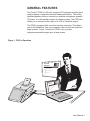
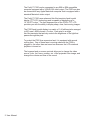
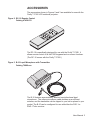
Telex®
User’s Manual
Firefly™ P350
LCD Notebook Projector
CAUTION
RISK OF ELECTRIC SHOCK
DO NOT OPEN
CAUTION: TO REDUCE THE RISK OF ELECTRIC SHOCK,
DO NOT REMOVE COVER (OR BACK)
NO USER-SERVICABLE PARTS INSIDE
REFER SERVICING TO QUALIFIED SERVICE PERSONNEL
The lightning flash with arrowhead symbol is displayed on the product to
alert the user to the presence of uninsulated “dangerous voltage” within
the product’s enclosure that may constitute a risk of electric shock.
The exclamation point symbol is displayed on the product to alert the
user to the presence of important operating and maintenance (servicing)
instructions in the literature that accompanies the product.
The heat warning symbol is displayed on the product to alert the user to
the presence of a hot surface that may constitute a risk of burns or fire.
IMPORTANT SAFETY INSTRUCTIONS
1. Read Instructions - All the safety and operating instructions should
be read before the product is operated.
2. Retain Instructions - The safety and operating instructions should be
retained for future reference.
3. Heed Warnings - All warnings on the product and in the operating
instructions should be adhered to.
4. Follow Instructions - All operating and use instructions should be
followed.
5. Cleaning - Unplug the product from the wall outlet before cleaning
any exterior surface. Follow the cleaning instructions in this manual.
6. Water and Moisture - Do not use this product near water - for
example, near a bathtub, washbowl, kitchen sink, laundry tub, in a
wet basement, or near a swimming pool, etc.
7. Ventilation - Slots and openings in the cabinet are provided for
ventilation and to ensure reliable operation of the product and to
prevent it from overheating. These slots and openings must not be
blocked or covered in any manner.
ii User Manual
8. Power Cord Protection - Power supply cords should be routed so
that they are not likely to be walked on or pinched by items placed
upon or against them, paying particular attention to cords at wall
outlets, convenience receptacles, and the point where they exit from
the product.
9. Lightning - For added protection for this product during a lightning
storm, or when it is left unattended and unused for long periods of
time, unplug it from the wall outlet. This will prevent damage to the
product due to lightning and power-line surges.
10. Overloading - Do not overload wall outlets, extension cords, or
integral convenience receptacles as this can result in a risk of fire or
electric shock.
11. Object and Liquid Entry - Care should be taken so that objects do
not fall and liquids are not spilled onto the product as they may touch
dangerous voltage points or short-out parts that could result in a fire
or electric shock.
12. Servicing - Do not attempt to service the product beyond that
described in the operating instructions as opening or removing
covers may expose you to dangerous voltage. All other servicing
should be referred to qualified service personnel.
13. Damage Requiring Service - Unplug this product from the wall outlet
and refer servicing to qualified service personnel when:
a. The power supply cord or the plug has been damaged.
b. Objects have fallen, or liquid has been spilled into the product.
c.
The product has been exposed to rain or water.
d. The product does not appear to operate normally or exhibits a
marked change in performance.
e. The product has been dropped, or the enclosure damaged.
14. Replacement Parts - When replacement parts are required, be sure
the technician has used replacement parts that have the same
characteristics as the original parts. Unauthorized substitutions may
result in fire, electric shock, or other hazards.
User Manual iii
Warranty
Telex warrants that the Firefly™ P350 will provide a usable active pixel
ratio of at least 99.995%. This means that out of 1.44 million pixels on
the Firefly™ P350, less than 50 pixels will be inactive.
Inactive pixels may appear illuminated on the display, however, they will
not affect picture quality or the life expectancy of the unit. If you have
any questions on this matter, please feel free to contact Telex
Communications, Inc.
FCC Statement
This equipment generates, uses, and can radiate radio frequency energy
that may cause interference to radio communications if not installed and
used in accordance with this manual. The equipment has been tested
and found to comply with the limits for a Class A computing device
pursuant to Subpart J, Part 15 of FCC Rules which are designed to
provide reasonable protection against such interference when operated
in a commercial environment. Operation of this equipment in a
residential area may cause interference which the user (at their own
expense) will be required to correct.
Canadian Department of Communications Statement
This digital apparatus does not exceed the Class A limits for radio noise
emissions from digital apparatus as set out in the Radio Interference
Regulations of the Canadian Department of Communications.
Le présent appareil numérique émet pas de bruits radioélectriques
dépassant les limites applicables aux appareils numériques de la classe
A prescrites dans le Règlement sur le brouillage radioélectrique édicté
par le Ministère des Communications du Canada.
™
Firefly is a trademark of Telex Communications, Inc.,
Minneapolis, Minnesota 55420
iv User Manual
TABLE OF CONTENTS
IMPORTANT SAFETY INSTRUCTIONS . . . . . . . . . . . . . . . . . ii
Warranty . . . . . . . . . . . . . . . . . . . . . . . . . . . . . . iv
FCC Statement . . . . . . . . . . . . . . . . . . . . . . . . . . . iv
Canadian Department of Communications Statement . . . . . . . iv
GENERAL FEATURES . . . . . . . . . . . . . . . . . . . . . . . . .
1
ACCESSORIES . . . . . . . . . . . . . . . . . . . . . . . . . . . .
3
UNPACKING THE P350 . . . . . . . . . . . . . . . . . . . . . . . .
4
P350 SETUP . . . . . . . . . . . . . . . . . . . . . . . . . . . . . .
6
Positioning the Firefly™ P350 On the Desktop
. . . . . . . . . .
6
Connecting the P350 . . . . . . . . . . . . . . . . . . . . . . . .
6
Remote Control Battery . . . . . . . . . . . . . . . . . . . . . . 11
OPERATION . . . . . . . . . . . . . . . . . . . . . . . . . . . . . . 12
Basic Operation . . . . . . . . . . . . . . . . . . . . . . . . . . 12
CONTROLS . . . . . . . . . . . . . . . . . . . . . . . . . . . . . . 15
Keypanel Controls . . . . . . . . . . . . . . . . . . . . . . . . . 15
Menu Mode On-Screen Controls . . . . . . . . . . . . . . . . . . 17
Illuminated Indicators . . . . . . . . . . . . . . . . . . . . . . . . 21
Remote Control
. . . . . . . . . . . . . . . . . . . . . . . . . . 21
CARE AND MAINTENANCE . . . . . . . . . . . . . . . . . . . . . . 22
Storage and Transportation . . . . . . . . . . . . . . . . . . . . 22
Lens Cleaning . . . . . . . . . . . . . . . . . . . . . . . . . . . 22
Lamp Replacement
. . . . . . . . . . . . . . . . . . . . . . . . 23
Fuse Replacement . . . . . . . . . . . . . . . . . . . . . . . . . 24
Troubleshooting Guide . . . . . . . . . . . . . . . . . . . . . . . 25
SERVICE INFORMATION . . . . . . . . . . . . . . . . . . . . . . . 28
TECHNICAL SPECIFICATIONS . . . . . . . . . . . . . . . . . . . . 29
ABBREVIATIONS . . . . . . . . . . . . . . . . . . . . . . . . . . . 31
INDEX
. . . . . . . . . . . . . . . . . . . . . . . . . . . . . . . . . 32
User Manual v
GENERAL FEATURES
The Firefly™ P350 is a full-color compact LCD projection system that is
used to display a computerized multi-media presentation. The built-in
amplifier/speakers lets you connect to a wireless microphone, portable
CD player, or to the auxiliary output of a stereo system. The P350 also
allows you to connect to the output of a VCR or LaserDisc player.
The P350 is equipped with a monitor interface connector. This allows
you to simultaneously view your computer video on both the small and
large screens. Figure 1 shows the P350 in use to project
computer-generated images onto a large screen.
Figure 1. P350 In Operation
The Telex
Difference
A System Approach
Flexible Yet Easy To Use
True Value
lex
The Te
nce
Differe
ach
m Appro
A Syste
Flexible
e
sy To Us
Yet Ea
e Value
Tru
User Manual 1
The Firefly™ P350 can be connected to any IBM or IBM compatible
computer equipped with a VGA/SVGA video output. The P350 can also
be connected to any Apple Macintosh computer that is equipped with a
standard Macintosh video output.
The Firefly™ P350 uses advanced thin-film-transistor liquid crystal
display (TFT LCD) technology and is capable of displaying up to
16,194,277 colors. The fast response time of the P350’s TFT LCD
provides you with the ability to display sharp, clear, fast-moving images.
The P350 liquid crystal display is a matrix of 1.44 million pixels arranged
in 600 rows x 800 columns x 3 colors. Each pixel is a single
thin-film-transistor that actively controls the brightness of the light that
passes through the pixel.
To protect the P350 from excessive heat, it is equipped with several
cooling fans. One of these fans is running whenever the P350 is
plugged in, the other fans are turned on whenever the LCD notebook
projector is turned on.
The keypanel and on-screen controls allow you to change the video
source, color, tint, focus, position, etc. of the projected color image; and
change the volume and tone of the sound.
2 User Manual
ACCESSORIES
The accessories shown in Figures 2 and 3 are available for use with the
Firefly™ P350 LCD notebook projector:
Figure 2. RC-10 Remote Control
Catalog 47436-033
B
LA
K
N
B
S
U
C
T
H
FO
IG
R
O
C
A
TR
N
T
S
V
O
E
M
LU
6
7
E
M
S
E
/R
U
N
E
T
The RC-10 is specifically designed for use with the Firefly™ P350. It
allows remote control of all the P350 keypanel and on-screen functions.
(The RC-10 comes with the Firefly™ P350.)
Figure 3. B-10 Lapel Microphone with Transmitter
Catalog 70889-xxx
on
ic
m ff
o
by
Te
x
le
The B-10 features a permanently attached omni-directional lapel
microphone. The unique microphone cable doubles as an efficient
antenna, and the transmitter can be clipped to your belt or placed in your
pocket. The B-10 can be configured for use with either the PAS-1 or
ENG-1 Telex receiver.
User Manual 3
UNPACKING THE P350
Unpack the Firefly™ P350 LCD notebook projector and check the
package contents. Refer to Figure 4 and the following list for items that
are included in the P350:
• P350 LCD notebook projector, with appropriate labels
• User’s manual
• Quick reference guide
• Adapter Redemption Card
• VGA/SVGA video cable
• Macintosh adapters for P350
(550093-002 and 550093-003)
• Audio cable (1/8" stereo phone to 1/8" stereo phone)
• Audio cable (dual RCA to 1/8" stereo phone adapter)
• Composite video (RCA to RCA)
• RC-10 Remote control
• Power cord (110V units only)
• Registration card
• Soft-sided case
• Warranty card
Contact your dealer if anything is missing or damaged.
☞
☞
4 User Manual
NOTE: The 550093-002 and 550093-003 adapters are for use with
Macintosh multisync monitors. (Telex part numbers 550093-000 and
550093-001 are for 640 x 480 Macintosh mode, while Telex part
numbers 550093-003 and 550093-004 are for 832 x 624 Macintosh
mode.)
NOTE: If the adapters that came with your P350 do not meet your
Macintosh computer requirements, complete and return the Adapter
Redemption Card.
Figure 4. P350 Package Contents
P-35
0
U
SO
C
R
E
T
H
IG
ER
W
PO
BR
T
S
A
TR
N
O
C
E
M
LU
VO
F1
F2
ET
ES
/R
U
EN
M
SOFTCASE
RC-10 REMOTE
POWER CORD
VGA/SVGA VIDEO CABLE
ADAPTERS
(Used on Macintosh units only)
AUDIO CABLE
Firefly P3
(dual RCA to 1/8" stereo)
Quick Re
Registra
Warranty
AUDIO CABLE
(1/8" stereo to 1/8" stereo)
50
ference Gu
tion Card
ide
Card
U ser's
Manual
Firefly P3
50
COMPOSITE VIDEO
(RCA to RCA)
User Manual 5
P350 SETUP
This section is a detailed description of the setup for your P350.
Positioning the Firefly™ P350 On the Desktop
1. Place the P350 on a table or desktop as shown in Figure 5.
☞
NOTE: Ensure that the P350 vents are not blocked. The P350 takes in
cool air at the side of the projector. Hot air is exhausted at the rear of the
P350.
WARNING! To prevent heat damage, keep all materials at least one
foot (30 cm) from the rear of the P350.
2. To determine the distance between projector and screen, refer to
Figure 5 and select the desired screen image size.
Figure 5. Distance vs Image Size
Projector Distance
From Screen
Image
Width
Image
Height
4 ft (1.2 m)
6 ft (1.8 m)
10 ft (3.0 m)
15 ft (4.6 m)
3.5 ft (0.9 m)
5.2 ft (1.3 m)
8.7 ft (2.2 m)
13.0 ft (3.3 m)
2.6 ft (0.7 m)
3.8 ft (1.0 m)
6.4 ft (1.6 m)
9.7 ft (2.5 m)
Connecting the P350
The P350 must be connected to a video source, and to an AC wall outlet.
The P350 can be connected to a computer monitor, audio source,
additional (composite or S-Video) video source and to an external
amplified stereo speaker system.
6 User Manual
The following describes the steps needed to connect the P350.
1. Turn off all equipment.
2. Slide the locking mechanism (Figure 6) to release, then lift the P350
to its raised position.
3. Plug the Firefly™ P350 into an AC wall outlet (the POWER button
will glow and one of the cooling fans will be turned on).
4. Audio input can be amplified by the P350 and heard over the built-in
speakers. Connect a stereo or mono audio source, such as the
auxiliary output of an amplifier, a wireless microphone system, CD
player, tape player, VCR or LaserDisc to the AUDIO IN jack (use one
of the two audio cables shown in Figure 4).
5. If desired, connect an external amplified, mono or stereo
system to the AUDIO OUT jack on the P350.
☞
speaker
NOTE: When a cable is plugged into the AUDIO OUT jack, the built-in
speakers are disabled.
Figure 6. Open and Close the Firefly™ P350
To Open, Slide
®
firefly
Press Button
to Close
User Manual 7
6. If you are using an IBM VGA/SVGA computer, the connections
are shown in Figure 7:
a. Unplug the monitor cable from the computer.
b. Plug one end of the supplied VGA/SVGA cable into the video
port of the computer.
c.
Plug the other end of the VGA/SVGA cable into the COMPUTER
jack on the Firefly™ P350.
d. To use your computer monitor along with your P350, plug the
monitor cable into the MONITOR jack on the Firefly™ P350.
Figure 7. P350 to IBM Connections
MONITOR
COMPUTER
AUDIO
in
out
VIDEO
s-video composite
VCR or
Laserdisc
Video
External
Amplified
Speaker
Line Level
Stereo Audio
Input
IBM Compatible PC
ehT
rot inoM giB
895789743
88 5326
Monitor
8 User Manual
Super VHS
Video
VCR or Laserdisc
Stereo Audio Input
(use dual RCA to
1/8" Stereo cable)
7. If you are using a Macintosh computer, the connections are
shown in Figure 8:
a. Unplug the monitor cable from the computer.
b. Plug the adapter labeled either “550093-0" or ”550093-2" into
the monitor port of the computer.
c.
Plug one end of the supplied VGA/SVGA cable into the adapter
on the computer.
d. Plug the other end of the VGA/SVGA cable into the COMPUTER
jack on the Firefly™ P350.
e. To use your computer monitor along with your Firefly™, select
the adapter labeled either “550093-1" or ”550093-3." Plug the
adapter into the MONITOR jack on the Firefly™ P350; plug the
computer monitor cable into the adapter.
☞
NOTE: Use the “550093-2" and ”550093-3" adapters with the 12-inch
Macintosh monitor, or the 15-inch Multisync monitor.
Figure 8. P350 to MacIntosh Connections
COMPUTER
AUDIO
in
out
MONITOR
MACINTOSH
COMPUTER &
MONITOR
External
Amplified
Speaker
Line Level
Stereo Audio
Input
ADAPTER
550093-001 or -003
ADAPTER
550093-000 or -002
VIDEO
s-video composite
Super VHS
Video
VCR or Laserdisc
Stereo Audio Input
(use dual RCA to
1/8" Stereo cable)
VCR or
Laserdisc
Video
User Manual 9
8. A video source such as a VCR or LaserDisc player can be
connected to the VIDEO and AUDIO jacks on the P350 as shown in
Figure 9:
a. Use the provided composite video cable to connect the VCR or
LaserDisc player to the COMPOSITE jack on the Firefly™ P350.
b. If your video system has S-Video capabilities, use the cable supplied with your video system to connect to the S-VIDEO jack on
the P350.
c.
Use the provided dual RCA to 1/8” stereo cable to connect the
audio output to the AUDIO IN jack on the Firefly™ P350.
Figure 9. VCR or LaserDisc Connections
COMPUTER
s-video composite
AUDIO CABLE
COMPOSITE VIDEO
(1/8" stereo to dual RCA)
(RCA to RCA)
L
R
10:00
Power
VCR or Laser Disc
CH 11 100234
VCR
Stop/Eject
10 User Manual
VIDEO
AUDIO
in
out
MONITOR
Play
Remote Control Battery
The remote control requires one 9V alkaline battery installed as shown in
Figure 10.
Figure 10. Remote Control Battery Installation
1. SLIDE THE BATTERY COVER
BACK AND LIFT OUT.
2. PLUG IN THE BATTERY AND
POSITION IT IN THE BATTERY
COMPARTMENT.
X
.
.A
.A
.S
U
N
,M X
S -X
LI 36
O 4 C
P 7 D
A 4 V
E : 9
N /N
IN P
M
.S
U
N X
,M X
S -X
LI 36
O 4 C
P 7 D
A 4 V
E : 9
N /N
IN P
M
.
PE
O
N
3. ALIGN THE TABS ON THE BATTERY
COVER WITH THE SLOTS IN THE
BACK CASE AND
REPLACE THE COVER.
4. CHECK THE OPERATION BY PRESSING
ANY KEY. THE LED INDICATOR
SHOULD BLINK RAPIDLY.
Y
DB
AN
ST
CU
FO
HT
IG
BR
S
ST
RA
NT
CO
LU
VO
X
CE
UR
SO
.
.A
.S
ME
U
N
,M X
S -X
LI 36
O 4 C
P 7 D
A 4 V
E : 9
N /N
IN P
M
N
PE
O
DE
MO
NU
ME
A new battery should be installed in the remote control unit under the
following circumstances:
• New remote control unit is received from the factory.
• LED on the remote control no longer lights when keys are pressed,
indicating a “dead” battery
• Operating distance between the remote control and the P350
becomes too short for your purposes, indicating a “weak” battery
Continue with the Operation section of this manual for instructions on the
use of your Firefly™ P350 LCD Notebook Computer Projector.
User Manual 11
OPERATION
After you have connected the Firefly™ P350 as described in the P350
Setup section of this manual, you are ready to begin using your P350
LCD notebook projector.
Basic Operation
1. Lift the mirror as shown in Figure 6.
2. Press POWER to turn on the P350 LCD notebook projector. The
keypanel will light up, the main cooling fans will turn on and the
projector lamp will turn on; initially the screen will be blue. After
initialization, the Telex logo will appear.
☞
NOTE: When the P350 is turned on after a complete cool-down, the
lamp will not reach full intensity for approximately one minute of
operation.
WARNING! To prevent burns when the P350 is operating, avoid
touching the lamp access door and the surrounding area.
3. Turn on the attached computer. The Telex logo will disappear and
the computer image will appear.
CAUTION! The cooling fans protect the Firefly™ P350 from heat
generated by the projector lamp. Always make sure that the air intake
and exhaust are not blocked.
4. Adjust the room lighting for optimum screen viewing. (The projector
lamp is automatically turned on when the P350 is turned on.)
5. Adjust the focus control (Figure 11) and keystone control (Figure 12)
for best screen image. (You should now leave the projector and
lamp on until your presentation begins.)
☞
NOTE: The keypanel and on-screen control settings will be the same as
they were when the P350 was last used, if ten seconds were allowed to
elapse before the P350 was disconnected from the AC wall outlet.
6. To improve the image phase adjustment, display a colorful image on
the computer screen and page to the on-screen SYNC control. (It is
easier to adjust the Firefly™ P350 with a colorful image.)
7. Turn on your audio source (CD player, wireless microphone,
amplifier auxiliary audio output, etc.).
12 User Manual
Figure 11. P350 Screen Focus
FOCUS
CONTROL
Figure 12. P350 Keystone Control
KEYSTONE EFFECT
TEL
EX
P350 Pr
ojecto
r
Align
ment
Align
ment
Align
ment
Align
ment
Align
ment
Align
ment
Align
ment
Align
ment
KEYSTONE
CONTROL
User Manual 13
8. Press VOLUME to adjust the volume of the P350 built-in speakers.
☞
NOTE: If you have an external powered speaker system plugged into
the AUDIO OUT jack, turn it on and adjust the volume of that external
system. (The level at the AUDIO OUT jack is controlled by VOLUME .)
9. Turn on and play the connected VCR, LaserDisc player, etc.
10. Press SOURCE on the P350 keypanel to select one of the video
inputs.
11. To further enhance or change the image on the Firefly™ P350, refer
to the Keypanel and Menu Mode On-Screen Control sections of this
manual.
☞
☞
NOTE: To maximize the image quality of NTSC, PAL or SECAM video,
the On-Screen controls are displayed in a low resolution mode. When
video input is displayed, the On-Screen controls will not appear as sharp
as when a computer input is displayed.
NOTE: Ten seconds after you make a change, the image
enhancements that you have made will be saved. These saved
enhancements will be used as the default settings the next time that you
activate your P350.
12. When your presentation is complete, press POWER to turn off the
projector and lamp.
☞
NOTE: The lamp may be turned off, then on again before it is allowed to
cool completely. However, this action will shorten the life of the lamp.
13. After the Firefly™ P350 has cooled and the main cooling fans have
stopped, you may unplug the P350 from the AC wall outlet.
☞
☞
14 User Manual
NOTE: To use your computer and monitor without disconnecting them
from the P350, the P350 must be plugged into an AC wall outlet. The
MONITOR jack on the Firefly™ P350 requires power to operate the
computer monitor.
NOTE: The projector does not need to be turned on to use the
MONITOR jack.
CONTROLS
The P350 keypanel and Menu Mode On-Screen controls allow you to
customize the projected image and enhance the appearance of your
presentation. The function of each keypanel and on-screen control is
described below and the keypanel is shown in Figure 13.
Figure 13. Firefly™ P350 Keypanel
brightness
+
contrast
volume
+
+
menu/
reset
5
4
2
-
-
-
source
3
6
menu
page
7
power
Keypanel Controls
☞
NOTE: All controls have on-screen graphics to indicate their relative
value or selection setting.
BRIGHTNESS
Press the upper (+) button of the BRIGHTNESS control to increase the
overall image brightness. Press the lower (-) button of the
BRIGHTNESS control to decrease the overall image brightness. When
either adjustment limit is reached, the on-screen indicator will stop
moving.
CONTRAST
Press the upper (+) button of the CONTRAST control to make the color
image more vivid. Press the lower (-) button of the CONTRAST control
to provide greater definition to the color image in the subtle shading
areas. When either adjustment limit is reached, the on-screen indicator
will stop moving.
VOLUME
Press the upper (+) button of the VOLUME control to increase the
volume of the built-in speakers, or increase the level at the AUDIO OUT
jack. Press the lower (-) button of the VOLUME control to decrease the
volume of the built-in speakers, or decrease the level at the AUDIO OUT
jack. When either adjustment limit is reached, the currently active
on-screen indicator will stop moving.
Alignment
Press 2 (left), 4 (right), 5 (up), or 3 (down) to move the image left,
right, up, or down. (There is no adjustment limit for the alignment
function; the image will continue moving and wrap around to the opposite
edge of the display.)
User Manual 15
☞
NOTE: The Alignment controls are functional only when the P350 is not
in “menu” mode.
MENU
This key controls the display of the on-screen control “menus.” If an
on-screen controls “menu” item is displayed, pressing this key will make
the display disappear (on-screen displays normally disappear after five
seconds). To enter “menu” mode and display the first page of on-screen
controls, press and release MENU/RESET, then press either the
page-up or page-down double-arrow key to “step” through the “menus”
until the desired On-Screen Control page is displayed.
RESET
To reset the Firefly™ P350 image to the original factory settings, press
and hold MENU/RESET until the on-screen display indicates READY
TO RESET (approximately five seconds). When the key is released the
P350 will reset, clearing all image enhancements that you have made,
restoring the factory settings as the default settings. (If MENU/RESET
is released before READY TO RESET is displayed, the factory settings
will not be restored.)
SOURCE
Press SOURCE to select video input from COMPUTER, VIDEO,
S-VIDEO jacks. If only one video source is “live,” the screen will go
blank for a moment, then return control to the “live” video source.
MENU/PAGE
The MENU/PAGE keys are used to step through the On-Screen control
pages. Each subsequent press of one of the MENU/PAGE double-arrow
keys will display another page of On-Screen controls. The 6 (page-up)
and 7 (page-down) keys may be used at any time.
POWER
Press POWER to turn off the projector and lamp. Press POWER again
to turn on the projector and lamp.
16 User Manual
Menu Mode On-Screen Controls
☞
NOTE: To maximize the image quality of NTSC, PAL or SECAM video,
the On-Screen controls are displayed in a low resolution mode. When
video input is displayed, the On-Screen controls will not appear as sharp
as when a computer input is displayed.
SYNC
WIDTH
ENGLISH
SYNC
To access the menu page with the SYNC function, press and release
MENU, page-up or page-down, then press either the up or down arrow
key to “step” to the line where SYNC is displayed. Press either the right
or left arrow key to select between 16 possible image phase adjustment
settings. An on-screen graphic will indicate the SYNC setting. SYNC
can be affected by the WIDTH control, refer to the Troubleshooting
Guide.
WIDTH
To access the menu page with the WIDTH function, press and release
MENU, page-up or page-down, then press either the up or down arrow
key to “step” to the line where WIDTH is displayed. Press the right arrow
key to expand the width of the image. Press the left arrow key to
contract the width of the image. An on-screen graphic will indicate the
relative value of the WIDTH setting. WIDTH may affect the SYNC
control, refer to the Troubleshooting Guide.
Language
To access the menu page with the language function, press and release
MENU, page-up or page-down, then press either the up or down arrow
key to “step” to the line where ENGLISH, FRANCAIS, DEUTSCH or
ESPAÑOL is displayed. Press either the right or left arrow key to “step”
through the four languages. The language selected will be displayed
on-screen.
User Manual 17
AA
BB
MIRROR
INVERSE
PALETTE
OFF
OFF
16M
MIRROR
To access the menu page with the MIRROR function, press page-down
two times or page-up five times, then press either the up or down arrow
key to “step” to the line where MIRROR is displayed. Press either the
right or left arrow key to switch between the standard or mirror (reverse)
image. An on-screen graphic will indicate the MIRROR setting.
INVERSE
To access the menu page with the INVERSE function, press page-down
two times or page-up five times, then press either the up or down arrow
key to “step” to the line where INVERSE is displayed. Press either the
right or left arrow key to switch between a positive and negative image.
An on-screen graphic will indicate the INVERSE setting.
PALETTE
To access the menu page with the PALETTE function, press page-down
two times or page-up five times, then press either the up or down arrow
key to “step” to the line where PALETTE is displayed. Press either the
right or left arrow key to switch between one of two color modes: 8-color
or 16,194,277-color. An on-screen graphic will indicate the PALETTE
setting.
VOLUME
BASS
TREBLE
VOLUME
18 User Manual
To access the menu page with the VOLUME function, press page-down
three times or page-up four times, then press either the up or down
arrow key to “step” to the line where VOLUME is displayed. Press the
right arrow key to increase the volume of the built-in speakers, or
increase the level at the AUDIO OUT jack. Press the left arrow key to
decrease the volume of the built-in speakers, or decrease the level at the
AUDIO OUT jack. An on-screen graphic will indicate the relative value of
the VOLUME setting.
BASS
To access the menu page with the BASS function, press
page-downthree times or page-up four times, then press either the up or
down arrow key to “step” to the line where BASS is displayed. Press the
right arrow key to increase the low tones in the speaker output. Press
the left arrow key to decrease the low tones in the speaker output. An
on-screen graphic will indicate the relative value of the BASS setting.
TREBLE
To access the menu page with the TREBLE function, press page-down
three times or page-up four times, then press either the up or down
arrow key to “step” to the line where TREBLE is displayed. Press the
right arrow key to increase the high tones in the speaker output. Press
the left arrow key to decrease the high tones in the speaker output. An
on-screen graphic will indicate the relative value of the TREBLE setting.
BRIGHTNESS
CONTRAST
TINT
BRIGHTNESS
To access the menu page with the BRIGHTNESS function, press
page-down four times or page-up three times, then press either the up or
down arrow key to “step” to the line where BRIGHTNESS is displayed.
Press the right arrow key to increase the overall image brightness.
Press the left arrow key to decrease the overall image brightness. An
on-screen graphic will indicate the relative value of the BRIGHTNESS
setting.
CONTRAST
To access the menu page with the CONTRAST function, press
page-down four times or page-up three times, then press either the up or
down arrow key to “step” to the line where CONTRAST is displayed.
Press the right arrow key to make the color image more vivid. Press the
left arrow key to provide greater definition to the color image in the subtle
shading areas. An on-screen graphic will indicate the relative value of
the CONTRAST setting.
TINT
To access the menu page with the TINT function, press page-down four
times or page-up three times, then press either the up or down arrow key
to “step” to the line where TINT is displayed. Press the right arrow key to
increase the red in the color image. Press the left arrow key to increase
the green in the color image. An on-screen graphic will indicate the
relative value of the TINT setting. This control can only be adjusted
when viewing a computer video image.
User Manual 19
LAMP HOURS
LAMP CYCLES
00009.7
00019
LAMP HOURS
To access the menu page with the LAMP HOURS function, press
page-down five times or page-up two times, then press either the up or
down arrow key to “step” to the line where LAMP HOURS is displayed.
An on-screen graphic will indicate the accumulated LAMP HOURS
value. As the P350 is used, the lamp hour value is incremented. The
average life expectancy of the metal halide lamp is 2,000 hours. When a
new lamp is installed, press either the right or left arrow key to reset the
LAMP HOURS value to zero.
LAMP CYCLES
To access the menu page with the LAMP CYCLES function, press
page-down five times or page-up two times, then press either the up or
down arrow key to “step” to the line where LAMP CYCLES is displayed.
An on-screen graphic will indicate the accumulated LAMP CYCLES
value. Every time the P350 lamp is turned on, the lamp cycle value is
incremented. When a new lamp is installed, press either the right or left
arrow key to reset the LAMP CYCLES value to zero.
TV
TV COLOR
TV SHARPNESS
ENGLISH
TV COLOR
To access the menu page with the TV COLOR function, press and
release MENU, page-up or page-down, then press either the up or down
arrow key to “step” to the line where TV COLOR is displayed. Press the
right arrow key to increase the amount of color in the image. Press the
left arrow key to decrease the amount of color in the image. An
on-screen graphic will indicate the relative value of the TV COLOR
setting. This control can only be adjusted when viewing a TV video
image.
TV SHARPNESS
To access the menu page with the TV SHARPNESS function, press and
release MENU55, page-up or page-down, then press either the up or
down arrow key to “step” to the line where TV SHARPNESS is
displayed. Press the right or left arrow key to select between the eight
image sharpness settings. An on-screen graphic will indicate the TV
SHARPNESS setting. This control can only be adjusted when viewing a
TV video image.
20 User Manual
Illuminated Indicators
POWER
The POWER button glows red when the P350 is plugged into an AC
wall outlet and is ready to be turned on; one of the cooling fans should
be running at this time.
Keypanel
When the keypanel is lit, indicates that the P350 is in operation; the
projector lamp should also be on.
Remote Control
The RC-10 remote control can be used to remotely change all of the
keypanel and on-screen control functions. When a remote control
button is pressed, the LED on the remote control blinks rapidly.
☞
NOTE: When the remote control operating distance becomes too short
for your purposes, install a fresh battery as described in the Remote
Control Battery section of this manual.
To use the remote control, point it at the front of the projector and press
a key, or “bounce” the IR signal off the viewing screen.
User Manual 21
CARE AND MAINTENANCE
Storage and Transportation
To prepare your P350 for transport, perform the following steps:
1. Press POWER to turn off the projector and lamp. (The main cooling
fans will continue turning for approximately three minutes.)
2. When the main cooling fans have stopped turning and the P350 is
cool, unplug the power cord.
3. Close the mirror into its storage position.
4. Close the P350 down to its storage position and engage the locking
mechanism.
☞
NOTE: Store and transport the Firefly™ P350 at temperatures between
0° and 140°F (-17° to 60°C). Avoid storage in automobiles during
seasonal temperature extremes. Automobile interior temperatures can
exceed 160°F (70°C) in summer and drop below -20°F (-29°C) in winter.
If the Firefly™ P350 has been exposed to extremely hot, cold or humid
conditions, allow it to stand at room temperature for 30 minutes before
use. Take care to protect the Firefly™ P350 from jarring impacts.
Lens Cleaning
1. Lift the mirror as shown in Figure 6.
2. Gently wipe the exposed lens surfaces with a clean, lint-free tissue
(slightly moistened with lens cleaner if necessary). Never pour lens
cleaner or other solvents on the lens elements.
CAUTION! Never use silicone-impregnated eyeglass tissues on the
coated projection lens.
22 User Manual
Lamp Replacement
1. Press POWER to turn off the projector and lamp. (The main cooling
fans will continue turning for approximately three minutes.)
WARNING! To prevent burns, allow the lamp access door and
projector lamp to cool before attempting to replace the lamp.
2. When the main cooling fans have stopped turning and the P350 is
cool, unplug the power cord.
3. Lower the mirror, then close the P350 down to its storage position.
4. Turn the P350 over on a flat, stable surface.
Figure 14. Lamp Replacement
Lamp
Compartment
Screws
User Manual 23
☞
NOTE: Typically, metal halide lamps have an average operating life of
approximately 2,000 hours. When the On-Screen LAMP HOURS shows
2,000 hours of operation, lamp failure may occur soon. You may elect to
replace the lamp, or continue using your P350 until the lamp actually fails.
5. Loosen the two lamp compartment screws shown in Figure 14.
(These are captive screws and should not be completely removed.)
6. Lift out the lamp compartment assembly.
7. Install a new lamp compartment assembly.
8. Tighten the two lamp compartment screws shown in Figure 14.
Fuse Replacement
Figure 15 shows the location of the fuse holder. Use a small flat-blade
screwdriver to pop the fuse holder out.
☞
NOTE: To access the fuseholder, the Firefly™ P350 must be in its
raised position with the power cord unplugged.
Replace the fuses only with the type and rating shown on the label. If the
module repeatedly blows fuses, return it for servicing.
Figure 15. Fuseholder Location
Use only with a 250V fuse
Employer uniquement avec
un fusible de 250V
FUSE
HOLDER
AC POWER
INPUT JACK
24 User Manual
Troubleshooting Guide
PROBLEM
POSSIBLE SOLUTIONS
Telex logo is displayed on Firefly™ P350
• Unit is working properly, but no video source is present.
No image projected from Firefly™ P350
•
•
•
•
•
•
•
•
Firefly™ not turned on.
Firefly™ not connected to AC wall outlet.
AC wall outlet defective.
Computer or video cable not secure.
No video signal from computer or video source.
Incompatible video signal from computer.
Projector lamp burned out.
Weak video signal or poor VCR tracking.
No image on computer monitor
•
•
•
•
Computer or monitor video cable not secure.
Monitor power off or disconnected.
Firefly™ not connected to AC wall outlet.
No video signal from computer.
•
•
•
•
•
•
Adjust brightness, tint, and contrast controls.
Wrong inverse mode; change INVERSE setting.
Signal from computer is monochrome.
Computer video cable not secure.
Select a different color mode using the PALETTE function.
Adjust room lighting.
Poor color or no color
Flickering or unstable image
•
•
•
•
Focus needed; use the SYNC control (there are 16 possible settings).
Computer video cable not secure.
Incompatible video signal from computer.
Adjust the WIDTH control.
User Manual 25
PROBLEM
POSSIBLE SOLUTIONS
Split image or partial image
• Image alignment needed; use up-down and left-right arrow keys.
• Incompatible video signal from computer.
• Reset the Firefly™ to factory default settings.
Power button not illuminated on keypanel
• Firefly™ not connected to AC wall outlet.
• Defective AC wall outlet.
No audio from built-in speakers
•
•
•
•
•
•
•
•
•
No audio source connected.
Firefly™ not turned on.
Firefly™ not connected to AC wall outlet.
AC wall outlet defective.
Audio source turned off.
Audio source not connected with appropriate video input.
Audio source and audio output cables are reversed.
Volume control is set too low.
External amplified speaker system connected to the AUDIO OUT jack.
Visible bright spots
• An inactive pixel may appear as a bright spot on the screen, however,
it will not affect picture quality or the life expectancy of the P350. (The
Firefly™ P350 may contain a maximum of 50 inactive pixels.)
Image contains one or more vertical bars
• Use the Menu Mode On-Screen Controls to adjust the WIDTH. (After
eliminating the vertical bars, use SYNC to sharpen the image.)
☞
26 User Manual
NOTE: When adjusting the WIDTH, if the left arrow adjustment
causes the number of bars to increase, use the right arrow adjustment
to eliminate the bars. If the right arrow adjustment causes the number
of bars to increase, use the left arrow adjustment to eliminate the bars.
PROBLEM
POSSIBLE SOLUTIONS
Image out of focus
• Adjust the focus and keystone controls for best screen image.
• Adjust SYNC control.
☞
☞
NOTE: If only portions of the image are out of focus and the SYNC
adjustment causes the out-of-focus portions to move, refer to the
solution described in the “vertical bars” problem.
NOTE: Displaying a cross-hatch pattern will aid in resolving any focus
adjustment problems.
No image on Macintosh monitor
• Incorrect Macintosh computer and monitor adapters.
(Use the 55093-002 and 550093-003 adapters with the 15-inch
Macintosh multisync monitor or with the 12-inch Macintosh monitor.
Use the 55093-000 and 550093-001 with non-multisync Macintosh
monitors. Use the 55093-003 and 550093-004 with 832 x 624
Macintosh monitors)
No screen image with Macintosh PowerBook
• PowerBook must be turned on after the P350 is connected. (Turn off
the PowerBook, then turn it on again.)
• Ensure that Monitor Mirroring is enable on the PowerBook control
screen.
Undefined or unresolved problem
• Before calling for technical assistance use the RESET control to
restore the factory default settings, then use the Keypanel and Menu
Mode On-Screen Controls to make your image enhancements.
User Manual 27
SERVICE INFORMATION
In the interest of promptness (if service is required), it is recommended
that you first contact the dealer from whom the equipment was
purchased. If modules are to be returned to the dealer or factory, they
should be shipped in the original packing material or carefully packed in
some other container with sufficient packing material to prevent damage.
Technical assistance is available from the Telex Customer Service
Department at the following address:
Customer Service Department
Telex Communications, Inc
9600 Aldrich Avenue South
Minneapolis, Minnesota 55420 USA
Telephone: (612) 884-4051
(Collect calls not accepted)
Return equipment for factory repair to:
Service Department
Telex Communications, Inc.
1720 East 14th Street
Glencoe, MN 55336 USA
☞
28 User Manual
NOTE: All equipment returned for repair must be accompanied by
documentation stating your return address, telephone number and proof
of date of purchase, along with a description of the problem. In lieu of
this, you may obtain a Return Authorization Form from our Customer
Service Department.
TECHNICAL SPECIFICATIONS
P350 Computer Compatibility
• IBM and IBM compatibles with SVGA (800 x 600)
• Macintosh computers with external video (832 x 624 and 800 x 600
modes)
• 640 x 480 mode supported by showing a window with the smaller
image
Computer Interface
HD-15 D-subminiature interface connector
Color Palette
• 8-color mode: 2 shades per color, 8 total colors
• 16M-color mode: 253 shades per color, 16,194,277 total colors
LCD Panel
• 6.4" (diagonal measure)
• Active matrix TFT
• Contrast ratio
60:1 minimum
100:1 typical
• 800 x 600 pixel resolution
• Pixel response time for the P350
tr = 10 msec typical
tf = 40 msec typical
Optical Lens
• 165 mm focal length
• Three element lens
Computer Video Requirements
• Red, Green, Blue signal input/output
(0 to 1.0V at 75 ohms impedance)
• Vertical sync frequency: 50 - 72 Hz
• Horizontal sync frequency: 31 - 48 kHz
User Manual 29
Composite Video Requirements
NTSC, PAL or SECAM composite video
S-Video Requirements
NTSC, PAL or SECAM video with
separate chrominance and luminance
Projection Lamp Requirements
270 Watt metal halide lamp
Input Power
• 325 Watts
• 120 VAC, 60 Hz; 230 VAC, 50/60 Hz; auto-sensing
Weight
8.9 lbs (4.0 kg)
Dimensions
2.7" (H) x 15.2" (L) x 10.7" (W)
(68 mm x 386 mm x 272 mm)
Environmental Requirements
• Storage temperature: 0° to 140°F (-17° to 60°C)
• Operating temperature: 32° to 90°F (0° to 32°C)
• Relative humidity: 95% (non-condensing) at 95°F (35°C)
30 User Manual
ABBREVIATIONS
AUX
B/W
CCIR
CD
CW
CCW
DOS
EP
FCC
LCD
LED
LP
ME-SECAM
NTSC
PAL
RAM
ROM
SECAM
SLP
SP
SVGA
S-VHS
TFT
VAC
VCR
VDC
VGA
VHS
Auxiliary
Black and white
Comite Consultatif International des Radio Communications
Compact disk
Clockwise
Counter-clockwise
Disk operating system
Extended play (same as SLP)
Federal Communications Commission
Liquid crystal display
Light emitting diode
Long play
Middle East SECAM
National Television System Committee
Phase alternation by line
Random access memory
Read only memory
Sequentiel Couleur A Memoire
Super long play (same as EP)
Standard play
Super VGA
Super VHS
Thin film transistor
Volts-alternating current
Video cassette recorder
Volts-direct current
Video graphics adapter
Video home system
User Manual 31
INDEX
A
accessories
adapter . .
alignment .
audio . . .
.
.
.
.
.
.
.
.
.
.
.
.
.
.
.
.
.
.
.
.
.
.
.
.
.
.
.
.
.
.
.
.
.
.
.
.
.
.
.
.
.
.
.
.
. . . . . . . 3
. . . . 4, 9, 27
. . . . . 15, 26
. 6 - 7, 12, 26
B
BASS . . . . . . . . . . . . . . . . . . . . . 19
battery . . . . . . . . . . . . . . . . . . . 11, 21
BRIGHTNESS . . . . . . . . . . . . 15, 19, 25
C
Caution . .
cleaning . .
color . . . .
compatibility
compatible
connect . .
connections
connector .
contract . .
contrast . .
.
.
.
.
.
.
.
.
.
.
.
.
.
.
.
.
.
.
.
.
.
.
.
.
.
.
.
.
.
.
.
.
.
.
.
.
.
.
.
.
.
.
.
.
.
.
.
.
.
.
.
.
.
.
.
.
.
.
.
.
.
.
.
.
.
.
.
.
.
.
.
.
.
.
.
.
.
.
.
.
. . . . . . . . 12, 22
. . . . . . . . . . 22
2, 15, 18 - 20, 25, 29
. . . . . . . . . . 29
. . . . . . . . 2, 29
. . . . . 1, 6 - 7, 10
. . . . . . . . 8-9
. . . . . . . . 1, 29
. . . . . . . . . . 17
. . . . 15, 19, 25, 29
D
default settings . . . . . . . . . 14, 16, 26 - 27
disconnected . . . . . . . . . . . . . . . . . 25
disconnecting . . . . . . . . . . . . . . . . . 14
E
ENGLISH . . .
enhance . . . .
enhancements
expand . . . .
.
.
.
.
.
.
.
.
.
.
.
.
.
.
.
.
.
.
.
.
.
.
.
.
.
.
.
.
.
.
.
.
.
.
.
.
.
.
.
.
.
.
.
.
.
.
.
.
. . . . 17
. 14 - 15
14, 16, 27
. . . . 17
F
fans . . . . . . . . . . . . 2, 7, 12, 14, 21 - 23
features . . . . . . . . . . . . . . . . . . . . 1
focus . . . . . . . . . . . . . . . 2, 12, 25, 27
32 User Manual
INDEX, CONT’D
FRENCH . . . . . . . . . . . . . . . . . . . 17
fuse holder . . . . . . . . . . . . . . . . . . 24
fuse replacement . . . . . . . . . . . . . . . 24
G
GERMAN . . . . . . . . . . . . . . . . . . . 17
I
incompatible
indicators . .
intensity . . .
INVERSE . .
.
.
.
.
.
.
.
.
.
.
.
.
.
.
.
.
.
.
.
.
.
.
.
.
.
.
.
.
.
.
.
.
.
.
.
.
.
.
.
.
.
.
.
.
.
.
.
.
.
.
.
.
.
.
.
.
25 - 26
. . . 21
. . . 12
. 18, 25
K
keypanel . . . . . . . . . . . . . . . 2, 15, 26
keystone . . . . . . . . . . . . . . . . . . . 12
L
lamp . . . . . . .
lamp access . . .
LAMP CYCLES . .
LAMP HOURS . .
lamp replacement .
language . . . . .
LCD . . . . . . . .
LED . . . . . . . .
lift . . . . . . . . .
locking . . . . . .
.
.
.
.
.
.
.
.
.
.
.
.
.
.
.
.
.
.
.
.
.
.
.
.
.
.
.
.
.
.
.
.
.
.
.
.
.
.
.
.
.
.
.
.
.
.
.
.
.
.
.
.
.
.
.
.
.
.
.
.
.
.
.
.
.
.
.
.
.
.
.
.
.
.
.
.
.
.
.
.
.
.
.
.
.
.
.
.
.
.
. 12, 16, 30
12, 23 - 24
. . . . . 20
. . . 20, 24
. . . . . 23
. . . . . 17
. 2, 29, 31
. 11, 21, 31
. . . . . 7
. . . 7, 22
M
MENU . . . . . . . . . . . . . . . 16 - 17, 20
mirror . . . . . . . . . . . . . . . . . . . 12, 18
P
PAGE . .
PALETTE
pixel . . .
POWER
.
.
.
.
.
.
.
.
.
.
.
.
.
.
.
.
.
.
.
.
.
.
.
.
.
.
.
.
.
.
.
.
.
.
.
.
.
.
.
.
. . . . . . . . . 16
. . . . . 18, 25, 29
. . . . . 2, 26, 29
. 7, 12, 14, 16, 21
User Manual 33
INDEX, CONT’D
R
raised position
release . . . .
remote control .
RESET . . . .
.
.
.
.
.
.
.
.
.
.
.
.
.
.
.
.
.
.
.
.
.
.
.
.
.
.
.
.
.
.
.
.
.
.
.
.
. . . . . 7, 24
. . . . . . . 7
. 3 - 4, 11, 21
. . . 16, 20, 27
.
.
.
.
.
.
.
.
.
.
.
.
.
.
.
.
.
.
.
.
.
.
.
.
.
.
.
.
.
.
.
.
.
.
.
.
.
.
.
.
.
.
.
.
.
.
.
.
.
. . . . . . . . . 28
12, 16 - 17, 20, 25
. . . . . . . 6, 12
. . . . . . . 14, 16
. . . . . . . . . 17
. . . . . . . 22, 30
. . 12, 17, 25 - 27
TINT . . . . . . .
TREBLE . . . . .
TV COLOR . . .
TV SHARPNESS
.
.
.
.
.
.
.
.
.
.
.
.
.
.
.
.
.
.
.
.
.
.
.
.
.
.
.
.
S
service .
settings .
setup . .
SOURCE
SPANISH
storage .
SYNC . .
.
.
.
.
.
.
.
.
.
.
.
.
.
.
.
.
.
.
.
.
.
T
.
.
.
.
.
.
.
.
.
.
.
.
.
.
.
.
.
.
.
.
.
.
.
.
.
.
.
.
.
.
.
.
19
19
20
20
V
vents . . . . . . . . . . . . . . . . . . . . . 6
video . . 1 - 2, 6, 8, 10, 14, 16, 20, 25 - 26, 29
VOLUME . . . . . . . . . . . . . . 14 - 15, 18
W
Warning . . . . . . . . . . . . . . . . 6, 12, 23
WIDTH . . . . . . . . . . . . . . . 17, 25 - 26
34 User Manual
38109-703 Rev B
October 1997