1
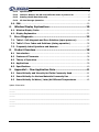
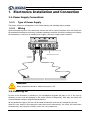
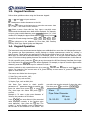
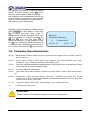
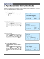
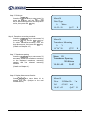
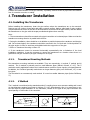
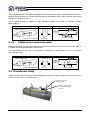
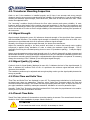
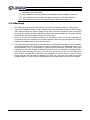
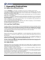
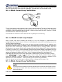
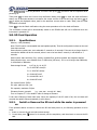
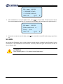
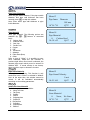
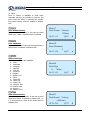
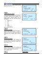
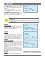
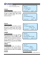
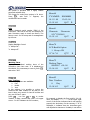
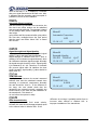
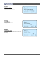
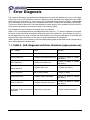
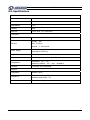
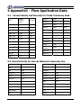
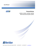
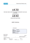
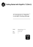
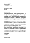
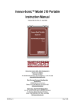
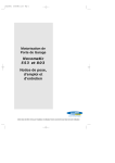
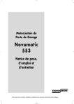
Ultrasonic Flowmeter Instruction Manual Model: LRF-3000H Revision:1.2 Date:Oct. 2014 Update Record Revision Date LRF-3000H Handheld Ultrasonic Flowmeter Notice Thank you for choosing the LRF-3000H Ultrasonic Flowmeter with SLSI CMOS and low-voltage wide-pulse transmission technology. This instruction manual contains important information. Please read carefully before operation of the flowmeter. WARNINGS IN THIS MANUAL Caution and warning statements are used throughout this book to draw your attention to important information. WARNING “Warning” statement appears with information that is important to protect people and equipment from harm or damage. Pay very close attention to all warnings that apply to your application. Failure to comply with these instructions may damage the meter. ATTENTION Failure to comply with these instructions may result in faulty operation. NOTE “Note” indicates that ignoring the relevant requirements or precautions may result in flowmeter damage or malfunction. Note: Some contents in this manual maybe different from the instrument you buy, which is because of the different configuration requirement when purchasing. On the other hand due to the need of the product improvement and upgrade, there is no remark on it, please be attention to the version number and the enclosed explanation. Version: 1.2 Page1 of 43 LRF-3000H Handheld Ultrasonic Flowmeter Product Components An inspection should be made of the desired location before installing the flowmeter. Check to see if the spare parts are present in accordance with the packing list. Make sure that there is no shipping damage. If you have any questions, please contact your representative as soon as possible. Version: 1.2 Page2 of 43 LRF-3000H Handheld Ultrasonic Flowmeter Table of Contents 1. Electronics Installation and Connection .................................... 5 1.1. Power Supply Connections .......................................................................... 5 1.1.1. Type of Power Supply ............................................................................................. 5 1.1.2. Wiring ...................................................................................................................... 5 1.2. Powering on ................................................................................................. 5 1.3. Keypad Functions ........................................................................................ 6 1.4. Keypad Operation ........................................................................................ 6 1.5. Flowmeter Menu Descriptions .................................................................... 7 2. Pipe Parameter Entry Shortcuts ................................................. 8 3. Measurement Site Selection..................................................... 10 4. Transducer Installation ............................................................ 11 4.1. Installing the Transducers ........................................................................ 11 4.1.1. Transducer Mounting Methods ............................................................................ 11 4.1.2. V Method ............................................................................................................... 11 4.1.3. Z Method ............................................................................................................... 12 4.1.4. N Method (not commonly used) .......................................................................... 12 4.2. Transducers fixing ..................................................................................... 12 4.3. Transducer Mounting Inspection .............................................................. 13 4.3.1 Signal Strength ........................................................................................................ 13 4.3.2 Signal Quality (Q value)........................................................................................... 13 4.3.3 Total Time and Delta Time ....................................................................................... 13 4.3.4 Transit Time Ratio .................................................................................................... 13 4.3.5 Warnings .................................................................................................................. 14 5. Operating Instructions .............................................................. 15 5.1. System Normal Identification ................................................................... 15 5.2. Low Flow Cutoff Value ............................................................................... 15 5.3. Zero Setting ............................................................................................... 15 5.4. Scale Factor ............................................................................................... 15 5.5. 4-20mA Current Loop Verification ............................................................ 16 5.6. 4~20mA Current Loop Output .................................................................. 16 5.7. 4-20mA Current Loop Verification ............................................................ 16 5.8. SD Card Operation ..................................................................................... 17 Version: 1.2 Page3 of 43 LRF-3000H Handheld Ultrasonic Flowmeter 5.8.1. Specifications ........................................................................................................ 17 5.8.2. Install or Remove the SD card while the meter is powered on .......................... 17 5.8.3. Reading the SD Data Externally ........................................................................... 18 5.8.4. SD Card Storage Operation .................................................................................. 18 5.9. ESN ............................................................................................................. 19 6. Window Display Explanations .................................................. 20 6.1. Window Display Codes .............................................................................. 20 6.2. Display Explanation ................................................................................... 21 7. Error Diagnosis ......................................................................... 35 7.1. Table 1. Self-diagnosis and Error Solutions (upon power on) ................. 35 7.2. Table 2. Error Codes and Solutions (during operation) ........................... 36 7.3. Frequently Asked Questions and Answers................................................ 37 8. Product Overview ..................................................................... 38 8.1 Introduction ............................................................................................... 38 8.2 Features of Flowmeter .............................................................................. 38 8.3 Theory of Operation................................................................................... 38 8.4. Applications ............................................................................................... 39 8.5. Specifications ............................................................................................. 40 9. Appendix1 - Flow Application Data .......................................... 41 9.1 Sound Velocity and Viscosity for Fluids Commonly Used......................... 41 9.2 Sound Velocity for Various Materials Commonly Use .............................. 41 9.3 Sound Velocity In Water (1 atm) At Different Temperatures .................. 42 Update Information: ____________________________________________________________________________________ ______ ____________________________________________________________________________________ ______ ____________________________________________________________________________________ ______ ____________________________________________________________________________________ ______ Version: 1.2 Page4 of 43 LRF-3000H Handheld Ultrasonic Flowmeter 1. Electronics Installation and Connection 1.1. Power Supply Connections 1.1.1. Type of Power Supply The factory offers one rechargeable 11.1V Lithium battery and matching battery charger. 1.1.2. Wiring Open the hinged top cover of the electronics. Shown from left to right on the panel of the LRF-3000H are the downstream transducer connector, upstream transducer connector, the battery recharge port (charge the transmitter or connect to a standby power supply), and the 4~20mA output connector. Down Stream SD Up Strea m Power Switch 4-20m A Charge turn off th e power before ! Please i nsert or pull out the SD card. Power Switch Battery Recharge Port SD Card 4 -20mA Output Connector U PST REAM DOWNSTREAM Downstream Transducer Upstream Transducer WARNING Wiring connections should be made when power is off. 1.2. Powering on As soon as the flowmeter is switched on, the self-diagnosis program will start to run. If any error is detected, an error code will displayed on the screen (see Error Diagnostics). After that, the system will run automatically using the programmed parameters. All the parameters input by the user will be saved permanently until they are changed by the user. When the user modif ies the parameters and removes the transducers, the meter will recalculate automatically, and operate normally under the new parameters. Version: 1.2 Page5 of 43 LRF-3000H Handheld Ultrasonic Flowmeter 1.3. Keypad Functions Follow these guidelines when using the flowmeter keypad: 0 ~ and 9 to input numbers. Backspace or delete characters to the left. > < and - Return to the last menu or open the next menu. Acts as “+” and “-” are used to enter numbers. + Select a menu. Press this key first, input a two-digit menu number and the selected menu data will be displayed. For example, to input a pipe outside diameter, press Menu 1 1 where “11” is the window ID to display the pipe outside diameter. Enter Enter/Confirm Menu Data Enter/Exit SD card storage interface. Rate 、 Total 、 Velocity 、 Fluid 、 Signal 、 .Are shortcuts to the windows for Flow Rate, POS Totalizer, Velocity, Fluid Type, Signal Quality and Diagnosis. Diagnosis 1.4. Keypad Operation The instrument setup and measurement displays are subdivided into more than 100 independent menus. The operator can input parameters, modify settings or display measurement results by “visiting” a specific menu. These menus are arranged by 2-digit serial numbers from 00~99, then using +0, +1, etc. Each menu ID code has a defined meaning. For example, menu 11 is the pipe outside diameter, while menu 25 is the mounting spacing between the transducers. Each menu is discussed later in this manual. To visit a specific menu, press the key at any time except the SD Card Storage Interface, then input the 2-digit menu ID code and that menu will be displayed. For example, to input or check the pipe outside 1 1 keys for window ID code 11. diameter, press the Menu Menu > < Another method to visit a particular menu is to press the + and Enter keys to scroll through the menus. For example, if the current menu is 30, press - key to enter menu 31, press the + button again to enter menu 30. < > The menus are divided into three types: 1) Data Type, such as M11, M12; 2) Selection Type, such as M14; 3) Display Type, such as M00, M01. Visit Data Type menus to check specific parameters. If parameter change is needed, just input the values then press Enter ; or press Enter first, then input the values and press Enter to confirm. Example 1: To enter a pipe outer diameter of 200mm, the procedure is as follows: 1 1 to enter Menu11 (the numerical Press value displayed currently is the previous pipe outer diameter). Now press the Enter key. The symbol “>” and a flashing cursor is displayed on the left side of the third line on the screen. The Menu Version: 1.2 new value can now be entered. Or input the value first then press Enter to confirm 2 0 0 Enter . Menu 11 Pipe Outer Diameter 200 mm 14:53:30 Q=00 R Page6 of 43 LRF-3000H Handheld Ultrasonic Flowmeter Visit Selection Type menus to check the related options. If need to modify it, press Enter first to enter the revised selection when the symbol “>” and a flashing cursor are displayed at the left end of the third line on the screen; or input numbers directly to select the option when the symbol “>” and a flashing cursor are displayed. Example 2: If the pipe material is “Stainless Steel”, 1 4 to enter Menu 14, then press press Enter to modify the option. Then, select “1. Stainless Steel” from the drop-down menu (you may cycle through the choices by pressing the /+ /and keys) and then press ENT to confirm the selection. It is also possible to press the 1 key to change the selection and wait until “1. Stainless Steel” is displayed on the second line of the screen. Then press the ENT key to confirm. Menu Menu14 Pipe Inner Diameter 0. Carbon Steel 14:54 :45 Q=97 R 1.5. Flowmeter Menu Descriptions 00~09 Display menus: Used to display flow rate, positive total, negative total, net total, velocity, date & time etc. 10~29 Setup menus: Used to enter pipe outer diameter, pipe wall thickness, fluid type, transducer type, transducer mounting and spacing, etc. 30~38 Flow units selection and totalizer operating menus: Used to select units of measurement. Other menus set/reset the various totalizer modes. 40~45 Zero Set Calibration, Scale Factor. 55~83 Input and output setup menus: current loop mode select, 4mA or 0mA output value, etc. 90~94 Diagnostics: signal strength quality (menu 90), TOM/TOS*100 (menu 91), sound velocity (menu 92), total time and delta time of the measured signal (menu 93), Reynolds number and K factor (menu 94). +0~+4 Appendix: Power on/off time, total working hours, on/off times etc. -0 4~20mA correction menu. ATTENTION “Hidden” menus are for hardware adjustment (set by the manufacturer). Version: 1.2 Page 7 of 43 LRF-3000H Handheld Ultrasonic Flowmeter 2. Pipe Parameter Entry Shortcuts Example: Let us assume you have a DN200 (8”) pipe, measuring water, Material is carbon steel with no liner. These parameters should be entered as follows: Step 1. Pipe outside diameter 1 1 keys to enter menu 11, Press enter the pipe outside diameter, then press the ENT key. Menu Step 2. Pipe wall thickness 1 2 key to enter menu 12, Press the enter the pipe wall thickness (wall thickness for various pipe schedules can be found in the appendix), then press the ENT key. Menu 11 Pipe Outer Diameter 200 mm 14:53:30 Q=00 R Menu Step 3. Pipe material 1 4 key to enter menu 14, Press the ENT + press the key, use the or key to select the pipe material from the drop-down menu, then press the ENT key. Menu > < Step 4. Liner material parameters (including thickness and sound velocity, if needed) 1 6 key to enter menu 16, Press the + press the ENT key, use the or key to select liner material from the drop-down menu, and then press the ENT key. Menu > < Version: 1.2 Menu 12 Pipe Wall Thickness 6 mm 14:54 :00 Q=00 Menu14 Pipe Material 0. Carbon Steel 14:54 :45 Q=97 Menu16 Liner Material 0. None, 14:55 :10 R R No Liner R Q=97 Page 8 of 43 LRF-3000H Handheld Ultrasonic Flowmeter Step 5. Fluid type 2 0 key to enter menu 20, Press the + press the ENT key, use the or key to select fluid type from the drop-down menu, then press the ENT key. Menu > < Step 6. Transducer mounting methods 2 4 key to enter menu 24, Press the ENT press the key, use the + or - key to select transducer-mounting from the drop-down menu, then press the ENT key. (Details on Charpter 4.1) Menu Menu20 Fluid Type 0. Water 14:55 :58 > < Q=97 R Menu24 Transducer Mounting 0. V 14:56 :20 Q=97 R Step 7. Transducer spacing > Press the - 2 5 key to enter menu 25, accurately install the transducer according to the displayed transducer mounting spacing and the selected mounting method. (Details on Chapter 4). Menu 25 Transducer Spacing 159.86mm 14:56:40 Q=97 R Step 8. Display Mesurement Results 0 1 to enter Menu 01 to Press display flow rate. (Subject to the real measurement.) Menu Version: 1.2 Menu 01 Flow 30280m3/h *R Vel 0.3863 m/s 14:43 :02 Q=97 R Page 9 of 43 LRF-3000H Handheld Ultrasonic Flowmeter 3. Measurement Site Selection When selecting a measurement site, it is important to select an area where the fluid flow profile is fully developed to guarantee a highly accurate measurement. Use the following guidelines to select a proper installation site: Choose a section of pipe that is always full of liquid, such as a vertical pipe with flow in the upward direction or a full horizontal pipe. Ensure enough straight pipe length at least equal to the figure shown below for the upstream and downstream transducers installation. Name Straight length of upstream piping Straight length of downstream piping L ≥5D 90o bend 10D min L ≥10D 10D min Detector L ≥10D L ≥50D Tee 0.5D min 10D min L≥5D L ≥30D D Diffuser 5D min L≥10D L ≥5D Reduce L≥10D L≥30D Valve Flow controlled upstream Flow controlled downstream Check valve Pump Stop valve L≥50D P Ensure that the pipe surface temperature at the measuring point is within the transducer temperature limits. Version: 1.2 Page 10 of 43 LRF-3000H Handheld Ultrasonic Flowmeter Consider the inside condition of the pipe carefully. If possible, select a section of pipe where the inside is free of excessive corrosion or scaling. 4. Transducer Installation 4.1. Installing the Transducers Before installing the transducers, clean the pipe surface where the transducers are to be mounted. Remove any rust, scale or loose paint and make a smooth surface. Apply a wide band of sonic coupling compound down the center of the face of each transducer as well as on the pipe surface, and then attach the transducers to the pipe with the straps provided and tighten them securely. Note: 1. The two transducers should be mounted at the pipe’s centerline on horizontal pipes. Make sure that the transducer mounting direction is parallel with the flow. 2. During the installation, there should be no air bubbles or particles between the transducer and the pipe wall. On horizontal pipes, the transducers should be mounted in the 3 o’clock and 9 o’clock positions of the pipe section in order to avoid any air bubbles inside the top portion of the pipe. 3. Refer to Transducer Mounting on Menu 25. 4. If the transducers cannot be mounted horizontally symmetrically due to limitation of the local installation conditions, it may be necessary to mount the transducers at a location where there is a guaranteed full pipe condition (the pipe is always full of liquid). 4.1.1. Transducer Mounting Methods Four transducer mounting methods are available. They are respectively: V method, Z method and N method . The V method is primarily used on small diameter pipes (DN100~300mm, 4”~12”). The Z method is used in applications where the V method cannot work due to poor signal or no signal detected. In addition, the Z method generally works better on larger diameter pipes (over DN300mm, 12”) or cast iron pipes. The N method is an uncommonly used method. It is used on smaller diameter pipes (below DN50mm, 2”). 4.1.2. V Method The V method is considered as the standard method. It usually gives a more accurate reading and is used on pipe diameters ranging from 50mm to 400mm (2”~16”) approximately. Also, it is convenient to use, but still requires proper installation of the transducer, contact on the pipe at the pipe’s centerline and equal spacing on either side of the centerline. Side View Upstream Transducer Section Top View Transducer Flow Flow Downstream Transducer Version: 1.2 Pipe Strap Transducer Space Page 11 of 43 LRF-3000H Handheld Ultrasonic Flowmeter 4.1.3. Z Method The signal transmitted in a Z method installation has less attenuation than a signal transmitted with the V method. This is because the Z method utilizes a directly transmitted (rather than reflected) signal which transverses the liquid only once. The Z method is able to measure on pipe diameters ranging from 25mm to 1200mm (1”~48”) approximately. Side View Upstream Transducer Section Top View Transducer Flow Flow Downstream Transducer 4.1.4. Transducer Spacing Pipe Strap N Method (not commonly used) With the N method, the sound waves traverse the fluid twice and bounce three times off the pipe walls. It is suitable for small pipe diameter measurement. The measurement accuracy can be improved by extending the transit distance with the N method (uncommonly used). Side View Upstream Transducer Section Top View Transducer Flow Flow Downstream Transducer Pipe Strap Transducer Spacing 4.2. Transducers fixing Transducers can stick onto the pipe with its magnetic steel racks. If need to fasten them, then can use the chains to make it firm. See below picture. 2.Switch the lock-nut to fasten the chain. 1.Wind the chain through the pipe and hang it on the hook. Version: 1.2 Page 12 of 43 LRF-3000H Handheld Ultrasonic Flowmeter 4.3. Transducer Mounting Inspection Check to see if the transducer is installed properly and if there is an accurate and strong enough ultrasonic signal to ensure proper operation and high reliability of the transducer. It can be confirmed by checking the detected signal strength, total transit time, delta time as well as transit time ratio. These checks are explained below. The “mounting” condition directly influences the flow value accuracy and system reliability. In most instances, apply a wide bead of sonic coupling compound lengthwise on the face of the transducer and stick it to the outside pipe wall to get good measurement results. However, the following inspections still need to be carried out in order to ensure a high reliability of the measurement and long-term operation of the instrument. 4.3.1 Signal Strength Signal strength (displayed in menu 90) indicates a detected strength of the signal both from upstream and downstream directions. The relevant signal strength is indicated by numbers from 00.0~99.9. 00.0 represents no signal detected while 99.9 represent maximum signal strength. Normally, the stronger the signal strength detected, the better the measurement. Adjust the transducer spacing to the best position and check to ensure that enough sonic coupling compound is applied during installation in order to obtain the maximum signal strength. This is essentially fine tuning the calculated spacing shown in menu 25 (transducer spacing). It may be slightly different. System normal opperation requires signal strength over 60.0, which is detected from both upstream and downstream directions. If the signal strength detected is too low, the transducer installation position and the transducer mounting spacing should be re-adjusted and the pipe should be re-inspected. If necessary, change the mounting to the Z method (Z has the highest signal strength). 4.3.2 Signal Quality (Q value) Q value is short for Signal Quality (displayed in menu 90). It indicates the level of the signal detected. Q value is indicated by numbers from 00~99. 00 represents the minimum signal detected while 99 represent the maximum. The transducer position may be adjusted and enough coupling used to get the signal quality detected as strong as possible. 4.3.3 Total Time and Delta Time “Total Time and Delta Time” are displayed in menu 93. The measurement calculations in the flowmeter are based upon these two parameters. Therefore, when “Delta Time” fluctuates widely, the flow and velocities fluctuate accordingly. This means that the signal quality detected is poor. It may be the result of poor pipe-installation conditions, inadequate transducer installation or incorrect parameter input. Generally, “Delta Time” fluctuation should be less than±20%. Only when the pipe diameter is too small or velocity is too low can the fluctuation be wider. 4.3.4 Transit Time Ratio Transit Time Ratio indicates if the transducer mounting spacing is accurate. The normal transit time ratio should be 100±3 if the installation is proper. Check it menu 91. ATTENTION If the transit time ratio is over 100±3, it is necessary to check: Version: 1.2 Page 13 of 43 LRF-3000H Handheld Ultrasonic Flowmeter (1) If the parameters (pipe outside diameter, wall thickness, pipe material, liner, etc.) have been entered correctly, (2) If the transducer mounting spacing is accordance with the display in menu 25, (3) If the transducer is mounted at the pipe’s centerline on the same diameter, (4) If the scale is too thick or the pipe mounting is distorted in shape, etc. 4.3.5 Warnings 1. Pipe parameters entered must be accurate; otherwise the flowmeter will not work properly. 2. During the installation, apply enough coupling compound to bond the transducer onto the pipe wall. While checking the signal strength and Q value, move the transducer slowly around the mounting site until the strongest signal and maximum Q value are obtained. The larger the pipe diameter, the more the transducer may have to be moved. 3. Check to be sure the mounting spacing is as calculated in menu 25 and the transducer is mounted at the pipe’s centerline on the same diameter. Note that you can adjust the spacing slightly as described above to fine tune the device. 4. Pay special attention to those pipes that formed by steel rolls (pipe with seams), since such pipe is always irregular. If the signal strength is always displayed as 0.00, that means there is no signal detected. Thus, it is necessary to check that the parameters (including all the pipe parameters) have been entered accurately. Check to be sure the transducer mounting method has been selected properly, the pipe is not worn-out, and the liner is not too thick. Make sure there is there is indeed fluid in the pipe or the transducer is not very close to a valve or elbow, and/or there are not too many air bubbles in the fluid, etc. Once you have ruled out all these possible reasons, if there is still no signal detected, the measurement site has to be changed. Version: 1.2 Page 14 of 43 LRF-3000H Handheld Ultrasonic Flowmeter 5. Operating Instructions 5.1. System Normal Identification Press the Menu 0 8 keys. If the letter “*R” displays on the screen, it indicates system normal. If the letter “E” is displayed, it indicates that the current loop output is over ranged by 120%. This refers to the settings in menu 57. Enter a larger value in menu 57, and the letter “E” will disappear. It can be ignored if no current loop output is used. If the letter “H” is displayed, it indicates that the ultrasonic signal detected is poor. For more information, please refer to “Error Diagnosis”. If the letter “G” is displayed, it indicates that system is adjusting the signal gain prior to the measurement. Also, it means system normal. Only when the adjustment takes too long without stopping, can system be identified as abnormal. Letter “I” indicates no signal is being detected. Check to see if the transducer wiring connections are correct, the transducers are securely installed, etc. Letter “J” indicates a hardware defect exists. Normally, such a defect is temporary; it could be eliminated by system reboot (power off and restart). For further information, please refer to “Error Diagnosis”. 5.2. Low Flow Cutoff Value The data in M41is Low Flow Cutoff Value. If the flow rate falls below the low flow cutoff value, the flow indification is driven to zero. This function can prevent the flow meter from reading flow after a pump as shut down but there is still liquid movement in the pipe, which will result in totalization error. Generally, 0.01m/s is recommended to enter as the low flow cutoff point. The low flow cutoff value has no relation to the measurement results once the velocity increase over the low flow cutoff value. 5.3. Zero Setting Once zero flow occurs, a zero point is established, i.e. as the measurement value reaches zero flow, it indicates as zero. It is necessary to establish the true zero flow condition and program that set point into the instrument. If the zero set point is not at true zero flow, an offset will occur. For an ultrasonic Flowmeter, the measurement difference from zero point cannot be ignored under low flow conditions. It is necessary to perform a zero set calibration to improve low flow measurement accuracy. Set Zero in Menu42, press Enter ,wait for the processing indication at the bottom right corner of the screen to reach“0”. Performing Set Zero with under flowing conditions may cause the flow to be displayed as “0”. If so, it can be recovered via Menu 43. 5.4. Scale Factor Scale factor refers to the ratio between “actual value” and “reading value”. For example, when the measurement is 2.00, and it is indicated as 1.98 on the instrument, the scale factor reading is 2/1.98. This means that the best scale factor constant is 1. However, it is difficult to keep the scale factor as “1” on the instrument especially in batch control operations. The difference is called “consistency”. The scale factor default is “1” for each instrument prior to shipment from the factory. The reason is that the scale factors in the flowmeter are only limited by two parameters, i.e. the crystal oscillation frequency and the transducer. It has no relation to any circuit parameters. During operation, if there still exists possible difference in pipe parameters, etc., the “scale factor” may be necessary to be changed when used on different pipes. Thus, scale factor calibration is specially designed Version: 1.2 Page 15 of 43 LRF-3000H Handheld Ultrasonic Flowmeter for calibrating the differences that result from application on different pipes. The scale factor entered must be one that results from actual flow calibration. The scale factor can be entered via M45. 5.5. 4-20mA Current Loop Verification 4-20mA+ Blue 4-20mABlack 4-20mA + 3 4 1 2 4-20mA - The 4~20mA current output connects to the 4-pin din jack on the panel. The color of cable core is blue (4-20mA+)and black (4-20mA-). With an accuracy of 0.1%, The current output of the Flowmeter PORTABLE is fully programmable and can be set to various output modes such as 4~20mA or 0~20mA. Use Window M55 to select the output mode. The max load of 4-20mA DC is 750Ω. Exercise care on polarity when connecting. 5.6. 4~20mA Current Loop Output With a current loop output exceeding an accuracy of 0.1%, the flowmeter is programmable and configurable with outputs such as 4 ~20mA or 0~20mA selected in menu M55. For details, please refer to “Window Display Explanations”. In Window M56, enter a 4mA flow value. Enter the 20mA flow value in Window M57. For example, if the flow range in a specific pipe is 0~1000m3/h, enter 0 in Window M56 and 1000 in Window M57. If the flow ranges from -1000~0~2000m3/h, configure the 20~4~20mA output by selecting Window M55 when flow direction is not an issue. Enter 1000 in Window M56 and 2000 in Window M57. When flow direction is an issue, an output of 0~4~20mA is available. When the flow direction displays as a negative value, the current output is in the range of 0~4mA, whereas the 4~20mA is for the positive direction. The output options are displayed in Window M55. Enter “-1000” in Window M56 and 2000 in Window M57. Calibrating and testing the current loop is performed in Window M58. Complete the steps as follows: > < Press Menu 5 8 Enter ,move + or to display “0mA”, “4mA”, “8mA”, “16mA”, “20mA” readings, connect an ammeter to test the current loop output and calculate the difference. Calibrate it if the difference is not within tolerance. Refer to Section 5.6 for Current Loop Verification. Check the present current loop output in Window M59 as it changes with change in flow. 5.7. 4-20mA Current Loop Verification NOTE Do not perform this operation unless the actual output current value is different from the value indicated inMenu 58 CL Check Verification. Every meter has been calibrated before leaving the factory. Calibrate the anolog input required to expand the hardware debugging menu as below procedures: Version: 1.2 Page 16 of 43 LRF-3000H Handheld Ultrasonic Flowmeter > Press Menu powering off. 0 Enter , enter the password “4213068” then press Enter . This action will be inoperative after < Then press Enter to enter the Current Loop Verification Mode, press Enter to enter the 4mA verification status, use an accurate ammeter to measure the output current of the current loop, and move + or to adjust the displayed values, wait for the ammeter current value to reach “4mA”, then the 4mA verification is finished. > Press Enter to do the 20mA verification using the same procedure as for the 4mA verification. The verification results will be automatically saved in the EPROM and will not be affected when the instrument is powered off. 5.8. SD Card Operation 5.8.1. Specifications Memory: 2 GB (Standard) Note: The SD card is a consumable item and updates quickly. Thus the configuration is base on the real time data received. Data collection update rate: user selectable: 5 seconds to 60 seconds. If the rate is set longer than 60 seconds the default will be 60 seconds; when is set to be less than 5 seconds, it will default to 5 seconds. Data content: date and time, flow, velocity, totalized flow, positive totalizer and negative totalizer. Data collection time: user selctable from 1~2880 mins (48 hours). If it is set is longer than 2880mins, it will default to 2880mins. Data storage format: 1=07-04-10, 14:16:33 2=+3.845778E+01m3/h 3=+1.451074E+00m/s 4=-0000010E+0m3 5=+0000002E+0m3 6=-0000012E+0m3 File system format: FAT16 File type: plain text file (.txt) File capacity: maximum 512pcs Filename format: yymmdd (yy - year, mm - month, dd - date) Turn to Charpter 5.7.4 for details if want to change a filename. It can save 120bytes of data each time. When the capacity of the SD card is full, the new data will override the earliest files automatically (it will rollover). 5.8.2. Install or Remove the SD card while the meter is powered on If the operator desires to insert or remove the SD card with power on, the following operation is to be used: 1. Insert or remove the SD card without data storage. 2. To save data, press button for 4 seconds, exit the acquisition, and then insert or remove the SD card. Data Version: 1.2 Page 17 of 43 LRF-3000H Handheld Ultrasonic Flowmeter ATTENTION Do not remove the SD card from the reader while actively collecting data. Processing the data directly from the SD card file location on the PC could result in lost or corrupt data if the SD card is removed while data is still being processed. 5.8.3. Reading the SD Data Externally Remove the SD card from the Flowmeter. The operator may then use a PC card reader to read the data on the card. Use “Converter.exe” software to convert the format when needed. File Converter Tool (Click “offline” buttom to enter the document conversion interface) Press “Converter” button and then convert the SD card data format from “.TXT “to “.XLS”, see below: Select the file to be converted in “Source File (*.txt), enter the directory path and the filename in “Destination File (*.xls), then press “Convert”. When “OK” is displayed means the conversion is completed. 5.8.4. SD Card Storage Operation 1. Insert the SD card,then press Data buttom to enter the SD card storage setting interface. File name :100308 Collection T :0120(m) Interval T :005(s) Press[ENT ] to start Version: 1.2 > < 2. If you need to modify the filename, acquisition time or acquisition interval, enter the number to modify it directly, press + or - button for line feed. Page 18 of 43 LRF-3000H Handheld Ultrasonic Flowmeter File name :100308 +3.600000E+03m/h +3.152638E+003m/h 0000 :08 Q=97 R 3. After modification or to use the default value, press Enter to store the data. The above picture shows the normal operation interface. (If it does not work normally, will be shown as the picture below.) File name :100308 Please insert card or Press[i ] Exit 0000 :08 Q=97 4. If yyou do not want to save the data, press 01. Data R for 4 seconds, then exit SD card storage, open Menu 5.9. ESN We provide the flowmeter with a unique electronic serial number to identify each flowmeter for the convenience of the manufacturer and customers. The ESN, instrument types and versions are able to view in Window M61. ATTENTION Other Operating Refer to “6.2 Window Display Explanations”. Version: 1.2 Page 19 of 43 LRF-3000H Handheld Ultrasonic Flowmeter 6. Window Display Explanations 6.1. Window Display Codes Flow Totalizer Display 37 Totalizer Reset 00 Flow Rate/Net Totalizer 38 Manual Totalizer 01 Flow Rate/Velocity Setup Options 02 Flow Rate/POS Totalizer 40 Damping 03 Flow Rate/NEG Totalizer 41 Low Flow Cutoff Value 04 Date Time/Flow Rate 42 Set Zero 08 System Error Codes 43 Reset Zero 09 Net Flow Today 44 Manual Zero Point Initial Parameter setup 45 Scale Factor 10 11 Pipe Outer Perimeter Pipe Outer Diameter Input and output setup 55 CL Mode Select 12 Pipe Wall Thickness 56 CL 4mA Output Value 13 Pipe Inner Diameter 57 CL 20mA Output Value 14 Pipe Material 58 CL Check 15 Pipe Sound Velocity 59 CL Current Output 16 Liner Material 60 Date and Time 17 Liner Sound Velocity 61 ESN 18 Liner Thickness 70 Backlit Options 20 Fluid Type 72 Working Timer 21 Fluid Sound Velocity 82 Date Totalizer 22 Fluid Viscosity 83 Automatic Correction 24 Transducer Mounting Diagnoses 25 Transducer Spacing 90 Signal Strength and Quality 26 Parameter Setups 91 TOM/TOS*100 27 28 29 Cross-sectional Area Holding with Poor Sig Empty Pipe Setup 92 Fluid Sound Velocity 93 Total Time and Delta 94 Reynolds Number and Factor Flow Units Options 30 Measurement Units 31 Flow Rate Units 32 Totalizer Units 33 Totalizer Multiplier 34 Net Totalizer 35 POS Totalizer 36 NEG Totalizer Appendix +0 Power ON/OFF time +1 Total Working Hours +2 Last Power Off Time +3 Last Flow Rate +4 ON/OFF Times -0 Hardware Parameter Modification NOTE:The factory maintains the final explanation for other menu features. Version: 1.2 Page 20 of 43 LRF-3000H Handheld Ultrasonic Flowmeter 6.2. Display Explanation Menu 0 0 Flow Rate/Net Totalizer Display flow rate and net Totalizer. If the net Totalizer has been turned off (refer to M34), the net Totalizer value displayed is the total that existed prior to turning it off. Menu 0 1 Flow Rate/Velocity Display flow rate and velocity. Menu 0 Display flow rate and positive Totalizer. Select the positive Totalizer units in Window M31. If the positive Totalizer has been turned off, the positive Totalizer value displayed is the total the total that existed prior to turning it off. 0 Display flow rate and negative Totalizer. Select the negative Totalizer value in Window M32. If the negative Totalizer has been turned off (refer to M36), the value displayed is total the total that existed prior to turning it off. 0 Menu02 Flow 30280m3/h *R POS +22435575x1m3 14:47 :42 Q=97 R 3 Flow Rate/Negative Totalizer Menu Menu01 Flow 30280m3/h *R Vel 0.3863 m/s 14:43 :02 Q=97 R 2 Flow Rate/Positive Totalizer Menu Menu00 Flow 30280m3/m *R NET +22435575x1m3 14:42 :42 Q=97 R Menu03 Flow 30280m3/m *R NEG - 62x1m3 14:48 :00 Q=97 R 4 Date Time/Flow Rate Display the current date time and flow rate. The time setting method is found in window M60. Version: 1.2 Menu 04 10- 03 - 08 14 :48 :59 *R Flow 30280m3/h 14:48 :59 Q=97 R Page 21 of 43 LRF-3000H Handheld Ultrasonic Flowmeter Menu 0 8 System Error Codes Display the operating condition and the system error codes. More than one error code can occur at the same time. The explanations of error codes and detailed resolution methods can be found in “Error Diagnosis”. Menu 0 1 1 Note: Enter either the pipe outside diameter or pipe outer perimeter. 1 Menu09 Net Flow Today M09 8.785678E06 m3 14:52 :29 Q=97 R Menu10 Pipe Outer Perimeter 3.14159 mm 14:53 :18 Q=97 R 1 Pipe Outside Diameter Enter the pipe outside diameter; the pipe outside diameter must range from 10mm to 600mm. Menu Q 0 Pipe Outer Perimeter Enter the pipe outer perimeter (circumference). If the diameter is known know, enter it in window M11. Menu Q 9 Net Flow Today Display net total flow today. Menu Menu08 *Q -------------No Signal Detected 14:51:24 Q = 00 Menu11 Pipe Outer Diameter 3.14159 mm 14:53 :30 Q=00 R 2 Pipe Wall Thickness Enter the pipe wall thickness. If the pipe inside diameter is already known, skip this window and enter it in window M13. Version: 1.2 Menu12 Pipe Wall Thickness 6 mm 14:54 :00 Q=00 R Page 22 of 43 LRF-3000H Handheld Ultrasonic Flowmeter Menu 1 3 > Pipe Inner Diameter Enter the pipe inside diameter. If the pipe outside diameter and pipe wall thickness has been entered, press - to skip this window. Note: Enter either pipe wall thickness or pipe inside diameter. Menu13 Pipe Inner 14:54 :30 Menu 1 4 1 > < Pipe Material Enter pipe material. The following options are + available (by 、 - buttons or numerical keys): 0. Carbon Steel 1. Stainless Steel 2. Cast Iron 3. Ductile Iron 4. Copper 5. PVC 6. Aluminum 7. Asbestos 8. Fiber Glass-Epoxy 9. Other Refer to item 9 “Other”; it is possible to enter other materials, which are not included in previous eight items. Once item 9 is selected, the relevant pipe sound velocity must be entered in Window M15. If sound velocity is not known, there are other ways to determine it onsite. Menu 1 Menu14 Pipe Material 0. Carbon Steel 14:54 :45 Q=97 R Menu15 Pipe Sound Velocity 0 m/s 14:55 :00 Q=97 R 5 Pipe Sound Velocity Enter pipe sound velocity. This function is only used when item 9 “Other” is selected in Window M14. At the same time, this window cannot be visited. It will be calculated automatically according to the existing parameters. Menu Diameter 588 mm Q=97 R 6 Select the Liner Material The following options are available: 0. None, No Liner 1. Tar Epoxy 2. Rubber 3. Mortar 4. Polypropylene 5. Polystryol 6. Ploystyrene 7. Polyester 8. Polyethylene 9. Ebonite Version: 1.2 Menu16 Liner Material 0. None, 14:55 :10 No Liner Q=97 R Page 23 of 43 LRF-3000H Handheld Ultrasonic Flowmeter 10. Teflon 11. Other Item 11 “Other” is available to enter other materials that are not included in previous ten items. Once the “Other” is selected, the relevant liner sound velocity must be entered in Window M17. Menu 1 7 Liner Sound Velocity Enter liner sound velocity. It only can be visited when item “ Other” in Window M16 is selected. Menu17 Liner Sound Velocity 1328m/s Q=97 R Menu18 Liner Thickness 2 14:55 :28 Q=97 R Menu20 Fluid Type 0. Water 14:55 :58 Q=97 R Menu21 Fluid Sound Velocity 1428.9m/s 14:56 :00 Q=97 R 14:55 :15 Menu 1 8 Liner Thickness Enter liner thickness. It only can be visited when a definite liner is selected in Window M16. Menu 2 0 Select Fluid Type The following options are available: 0. Water 1. Sea Water 2. Kerosene 3. Gasoline 4. Fuel Oil 5. Crude Oil 6. Propane 7. Butane (0◦C) 8. Other 9. Diesel Oil 10. Castor Oil 11. Peanut Oil 12. Gasoline #90 13. Gasoline #93 14. Alcohol 15. Water (125◦C) Menu 2 1 Fluid Sound Velocity Enter the fluid sound velocity. It only can be used when item “Other” is selected in window M20, i.e. it is unnecessary to enter all the fluids listed in Window M20. Version: 1.2 Page 24 of 43 LRF-3000H Handheld Ultrasonic Flowmeter Menu 2 2 Fluid Viscosity Enter fluid’s kinematics viscosity. It only can be used when item “Other” is selected in Window M20, i.e. it is unnecessary to enter all the fluids that listed in Window M20. Menu 2 Four mounting methods are available: 0. V (sound wave bounces 2 times) 1. Z (sound wave bounces once. The most commonly use method) 2. N (small pipe, sound wave bounces 3 times.) 2 2 2 R Menu25 Transducer Spacing 514.603mm 14:56 :40 Q=97 R 6 Initial Parameter Setups and Save Load and save the parameters. 18 different sets of setup conditions/groups are available to load and save by three methods (i.e.-you can load and save 18 different applications): 0. Entry to Save 1. Entry to Load 2. To Browse Select “Entry to Save”, press Enter . An ID code and the original parameters are displayed in the window. Press UP or DOWN ARROW to move the ID code, then press the Enter key again to save the current parameter in the current ID file. When selecting “Entry to Load”, press ENT, and the system will read and calculate the parameters automatically and display the transducer mounting spacing in Window M25. Menu Menu24 Transducer Mounting 0. V 14:56 :20 Q=97 5 Transducer Spacing (This value is Calculated by the Flowmeter) The operator must mount the transducer according to the transducer spacing displayed (be sure that the transducer spacing is measured precisely during installation). The system will display the data automatically after the pipe parameter has been entered. Menu R 4 Transducer Mounting Menu Menu22 Fluid Viscosity 1.0038 cST 14:56 :09 Q=97 Menu26 Parameters Setups Entry to SAVE 14:57 :00 Q=97 R 7 Cross-Sectional Area Display the cross-sectional area inside the pipe. Version: 1.2 Menu 27 Cross - sectional Area 271547 mm2 14:57 :20 Q=97 R Page 25 of 43 LRF-3000H Handheld Ultrasonic Flowmeter Menu 2 8 Holding With Poor Sig Select “Yes” to hold last good flow signal displayed if the flowmeter experiences a poor temporary signal condition. This function will allow continued data calculation without interruption. Menu 2 3 3 36 Q=97 R Menu30 Measurement Units In 0. Metric 14:58 :23 Q=97 R Menu31 Flow Rate Units m3/m 14:59 :10 Q=97 R 14:58 :10 1 Flow Rate Units Options The following flow rate units are available: 0. 1. 2. 3. 4. 5. 6. 7. 8. Menu29 Empty Pipe Setup 0 Measurement Units Select the measurement unit as follows: 0. Metric 1. English Factory default is metric. Menu R 9 Empty Pipe Setup This parameter is used to overcome the possible problems that usually show up when the pipe being measured is empty. Since signals can be transmitted through the pipe wall, the flow meter may still read a flow while measuring an empty pipe. To prevent this from happening, you can specify a value. When the signal quality falls below this value, the measurement stops automatically. If the flow meter is already able to stop measuring when the pipe is empty, a value in the range of 30 to 40 should also be entered in this window to ensure no measurement when the pipe is empty. It should be understood that the instrument is NOT designed to function correctly on an empty pipe. Menu Menu28 Holding with PoorSig YES 14:57 :40 Q=97 Cubic Meters Liters USA Gallons Imperial Gallons Million Gallons Cubic Feet USA Barrels Imperial Barrels Oil Barrels (m3) (L) (GAL) (Imp gal) (mg) (cf) (US bbl) (Imp bbl) (Oil bbl) The following time units are available: /Day /Hour /Min /Sec Factory default is Cubic Meters/hour. Menu 3 2 Totalizer Units Options Select Totalizer units. The available unit options are as same as those found in Window M31. The Version: 1.2 Page 26 of 43 LRF-3000H Handheld Ultrasonic Flowmeter user can select units as their required. Factory default is Cubic Meters. Menu 3 3 Totalizer Multiplier Options The Totalizer multiplier acts as the function to increase the totalizer indicating range. Meanwhile, the Totalizer multiplier can be applied to the positive Totalizer, negative Totalizer and net Totalizer at the same time. The following options are available: 0. x 0.001 (1E-3) 1. x 0.01 2. x 0.1 3. x 1 4. x 10 5. x 100 6. x 1000 7. x 10000(1E+4) Factory default factor is x1 Menu 3 3 3 3 Menu34 NETTotalizer ON 15:00 :50 Q=97 R Menu35 POS Totalizer 15:01:00 ON Q=97 R 6 ON/OFF NEG Totalizer ON/OFF negative totalizer. “ON” indicates the totalizer is turned on. When it is turned off, the negative totalizer displays in Window M03. Factory default is “ON”. Menu R 5 ON/OFF POS Totalizer On/off positive totalizer. “ON” indicates the flowmeter starts to totalize. When it is turned off, the positive totalizer is displayed in Window M02. Factory default is “ON”. Menu Menu33 Totalizer Multiplier 3. x1 14:59 :50 Q=97 4 ON/OFF Net Totalizer On/off net Totalizer. “ON” indicates the totalizer is turned on, while “OFF” indicates it is turned off. When it is turned off, the net totalizer displays in Window M00 will not change. Factory default is “ON”. Menu Menu32 Totalizer Units Cubic Meters (m3) 14:59 :30 Q=97 R 7 Version: 1.2 Menu36 NEGTotalizer 15:01:20 ON Q=97 R Totalizer Reset Page 27 of 43 LRF-3000H Handheld Ultrasonic Flowmeter > < Totalizer reset; all parameters are reset. Press Enter ; move + or - arrow to select “YES” or “NO”. After “YES” is selected, the following options are available: None, All, NET, POS, NEG If it is necessary to recover the factory default , press keys after the above-mentioned characters are displayed on the screen. Generally, it is unnecessary to activate this function except during the initial installation. Menu37 Totalizer Reset Selection 15:01:40 Q=97 R ATTENTION: This operation will cancel all the data and revert back to factory default. Be careful with this operation. Menu 3 8 Manual Totalizer The manual totalizer is a separate totalizer. Press Enter to start, and press Enter to stop it. It is used for flow measurement and calculation. Menu 4 0 Damping The damping factor ranges from 0~999 seconds. 0 indicates no damping; 999 indicate the maximum damping. The damping function will stabilize the flow display. Usually a damping factor of 3 to 10 is recommend in most applications. Menu 4 1 Low Flow Cutoff Value If the flow rate falls below the low flow cutoff value, the flow indication is driven to zero. This function can prevent the flowmeter from reading flow after pump shut down but there is still liquid movement in the pipe, which will result in totalization error. Generally, 0.03m/s is recommended to enter as the low flow cutoff point. The low flow cutoff value has no relation to the measurement results once the velocity increases over the low flow cutoff Menu 4 Menu38 Manual Totalizer Press ENT When Ready 15:01:58 Q=97 R 2 Set Zero When fluid is in the static state (no movement), Version: 1.2 Menu40 Damping 15:02 :10 1 sec Q=97 R value. Menu41 Low Flow Cutoff Val 0.01m/s 15:02 :20 Q=97 R the displayed value is called “Zero Point”. When “Zero Point’ is not at true zero in the flowmeter, the difference is going to be added into the actual Page 28 of 43 LRF-3000H Handheld Ultrasonic Flowmeter flow values and measurement differences will occur in the flowmeter. Set zero must be carried out after the transducers are installed and the flow inside the pipe is in the absolute static state (no liquid movement in the pipe). Thus, the“Zero Point” resulting from different pipe mounting location and parameters can be eliminated. The measuring accuracy at low flow is enhanced by doing this function and flow offset is eliminated. Press ENT , wait for the processing instructions at the bottom right corner of the display to reach 0. Performing Set zero with existing flow may cause the flow to be displayed as “0”. If so, it can be recovered via Window M43. Menu 4 Menu42 Set Zero Press ENT to go 15:02 :30 Q=97 R 3 Reset Zero Select “YES”; reset “Zero Point” which was set by the user. Menu 4 Menu43 Reset Zero NO 15:02 :58 Value Deviation 5 . 5 Scale Factor The scale factor is used to modify the measurement results. The user can enter a numerical value other than “1” according to calibration results. Menu Menu44 Manual ZeroPoint 0 m3/h 15:03 :15 Q=97 R =10 m3/H Flowmeter Display =240 m3/H Normally, set the value as “0”. 4 R 4 Manual Zero Point This method is not commonly used. It is only suitable for experienced operators to set zero under conditions when it is not preferable to use other methods. Enter the value manually to add to the measured value to obtain the actual value. For example: Actual measured value =250 m3/H Menu Q=97 Menu45 Scale Factor 15:03 :15 1 Q=97 R 5 Current Loop Mode Select Version: 1.2 Page 29 of 43 LRF-3000H Handheld Ultrasonic Flowmeter Menu 5 0. 4-20mA output mode 1. 4-20mA Corresponding Velocity 6 CL 4mA Output Value Set the CL output value according to the flow value at 4mA. The flow unit’s options are as same as those in Window M31. Once “velocity 4-20mA”is selected in Window M55, the unit should be set as m/s if it is the velocity unit selected. Menu 5 5 < > 5 6 Menu57 CL 20mA Output Value 681300 m3/h 15:03 :50 Q=97 R Menu58 CL Checkup Press ENT When Ready 15:04 :20 Q=97 R 9 CL Current Output Display CL current output. The display of 10.0000mA indicates that CL current output value is 10.0000mA. If the difference between displaying value and CL output value is too large, the current loop then needs to be re-calibrated accordingly. Menu Menu56 CL 4mAOutput Value 1 m3/h 15:03 :30 Q=97 R 8 CL Check Verification Check if the current loop has been calibrated + before leaving the factory. Press Enter move or - separately to display 0mA, 4mA till 24mA, and at the same time, check with an ammeter to verify that CL output terminals M31 and 32 agree with the displayed values. It is necessary to re-calibrate the CL if it is over the permitted tolerance. For more information, refer to “Analog Output Calibration”. Menu R 7 20mA Output Value Set the CL output value according to the flow value at 20mA. The flow unit is the as same as that found in Window M31. Once “velocity 4-20mA”is selected in Window M55, the unit should be set as m/s, if m/s is the velocity selection. Menu Menu55 CL Mode Select 0. 4- 20mA 15:03 :30 Q=97 0 Version: 1.2 Menu59 CL Current Output 3.9999mA 15:04 :40 Q=97 R Date and Time Settings Generally, it is unnecessary to modify date time as Page 30 of 43 LRF-3000H Handheld Ultrasonic Flowmeter the system is provided with a highly reliable perpetual calendar chip. The format for setting time setting is 24 hours. Press Enter , wait until “>” appears, the modification can be made. Menu 6 7 Menu70 LCD Backlit Option 1. Always ON 15:06 :10 Q=97 “1. Always On”; “0. Always off”. 7 2 8 2 Working Timer 00000417 :08 :00 15:06 :20 Q=97 R Menu82 Date Totalizer 0. Day 15:08 :05 R Q=97 > < Date Totalizer The following options are available: 0. Day 1. Month 2. Year In this window, it is possible to review the historical flow data Totalizer for any day for the last 64 days, any month for last 64 months and any year for last 5 years. + Press Enter , use the or to review Totalizer in days, months and years. Left upper corner: “00-63” indicates the file numbers; Version: 1.2 R Menu72 Working Timer Display the totalized working hours of the Flowmeter since last reset. It is displayed by HH:MM:SS. If it is necessary to reset it, press Enter , and select “YES”. Menu Menu61 Ultrasonic Flowmeter S/N =12580001 15:05 :10 Q=97 R 0 Display Backlight Control Menu :SS HH:MM 15:05 :00 Q=97 R 1 ESN Display electronic serial number (ESN) of the instrument. This ESN is the only one assigned to each flowmeter ready to leave the factory. The factory uses it for file setup and for management by the user. Menu Menu60 YY- MM - DD 10- 03 - 08 15:05 :00 For example, to display the flow total for July 18, 2000, the display “------------” at the upper right corner of the screen indicates that it was working properly the whole day. On the contrary, if “G” is displayed, it indicates that the instrument gain was adjusted at leastonce. Probably it was offline Page 31 of 43 LRF-3000H Handheld Ultrasonic Flowmeter once on that day. If “H” is displayed, it indicates that poor signal was detected at least once. Also, it indicates that the operation was interrupted or problems occurred in the installation. Menu 8 3 Automatic Flow Correction With the function of automatic flow correction, the flow lost in an offline session can be estimated and automatically adjusted. The estimate is based on the average value, which is obtained from flow rate before going offline and flow measured after going online the next time, multiplied times the time period that the meter was offline. Select “NO” to cancel this function. Menu 9 9 9 Menu90 Strength+Quality UP:90.5 DN:90.0 Q=97 15:08 :25 Q=97 R 1 TOM/TOS*100 Display the ratio between the actual measured transmit time and the calculated transmit time according to customer’s requirement. Normally the ratio should be 100±3%. If the difference is too large, the user should check that the parameters are entered correctly, especially the sound velocity of the fluid and the installation of the transducers. This data is of no use before the system is ready. Menu R 0 Signal Strength and Signal Quality Display the measured signal strength and signal quality Q value upstream and downstream. Signal strength is indicated from 00.0~99.9. A reading of 00.0 indicates no signal detected, while 99.9 indicates maximum signal strength. Normally the signal strength should be ≥60.0. Signal quality Q is indicated by 00~99. Therefore, 00 indicates the poorest signal while 99 indicates the best signal. Normally, signal quality Q value should be better than 50. Menu Menu83 Automatic Correction OFF 15:08 :15 Q=97 Menu91 TOM/TOS*100 0.0000 15:08 :45 Q=97 R 2 Fluid Sound Velocity Display the measured fluid sound velocity. Normally this value should be approximately equal to the entered value in Window M21. If the Version: 1.2 difference is too large, it probably results from an incorrect value entered in Window M21 or improper installation of the transducers. Page 32 of 43 LRF-3000H Handheld Ultrasonic Flowmeter Menu 92 Fluid Sound Velocity 1482.6 m/s 15:08 :56 Q=97 Menu R 3 9 Total Time and Delta Time Display the measured ultrasonic average time (unit: nS) and delta time of the upstream and downstream (unit: nS) time. The velocity calculation in the Flowmeter is based on the two readings. The delta time is the best indication that the instrument is running steadily. Normally the fluctuation in the ratio of the delta time should be lower than 20%. If it is not, it is necessary to check if the transducers are installed properly or if the parameters have been entered correctly. Menu < + Menu94 Reynolds Number 292582 0.7500 15:08 :34 Q=97 R 0 Power ON/OFF Time To view the power on/off time and flow rate for the last 64 update times to obtain the offline time period and the corresponding flow rate. Enter the window, press ENT to display the last update before the last 64 times of on/off time and flow rate values. “ON” on right hand indicates that time power is on; “00” on the upper left corner indicates “00-07-18 12:40:12” the date time; flow rate is displayed in the lower right corner. < Menu R 4 9 Reynolds Number and Factor Display the Reynolds number that is calculated by the Flowmeter and the factor that is set currently by the Flowmeter. Normally this scaling factor is the average of the line and surface velocity factor inside the pipe. Menu Menu93 Totl Time, Delta Time 0.0000uS ,- 1357.0nS 15:08 :13 Q=97 + Menu+0 ON/OFF Time Press ENT When Ready R 15:08 :59 Q=97 1 Total Working Hours With this function, it is possible to view the total working hours since the flowmeter left the factory. Version: 1.2 Menu+1 Total Work Hours 00000517 :23 :40 15:09 :12 Q=97 R Page 33 of 43 LRF-3000H Handheld Ultrasonic Flowmeter < Menu + 2 Last Power Off Time Display the last power off time. < Menu + 3 Last Flow Rate Display the last flow rate. < Menu + Menu+2 Last Power Off Time 10- 03 - 08 13 :57 :20 15:09 :34 Q=97 R Menu+3 Last Flow Rate 0 m3/h 15:09 :48 Q=97 R 4 Total ON/OFF Times Display total on/off times since the flowmeter left the factory. Menu+4 ON/OFF Times 15:09 :59 Version: 1.2 460 Q=97 R Page 34 of 43 LRF-3000H Handheld Ultrasonic Flowmeter 7. Error Diagnosis The ultrasonic Flowmeter has advanced self-diagnostics functions and displays any errors in the upper right corner of the LCD via definite codes in a date/time order. Hardware error diagnostics are usually performed upon each power on. Some errors can be detected during normal operation. Undetectable errors caused by incorrect settings and unsuitable measurement conditions can be displayed accordingly. This function helps to detect the errors and determine causes quickly; thus, problems can be solved in a timely manner according to the solutions listed in the following tables. Errors displayed in the Flowmeter are divided into two categories: Table 1 is for errors displayed during self-diagnostics upon power on. “*F” may be displayed on the upper left corner of the screen after entering the measuring mode. When this occurs, it is necessary to power on for self-diagnostics once again to detect and solve possible errors using the table below. If a problem still exists, please contact the factory or the factory’s local representative for assistance. Table 2 applies when errors caused by incorrect settings and signals are detected and are announced by error codes displayed in Window M08. 7.1. Table 1. Self-diagnosis and Error Solutions (upon power on) Cause Solution Rom Parity Error * System ROM illegal or error * Contact the factory Stored Data Error * System stored data block error * Power on again or contact the factory SCPU Fatal Error * SCPU circuit fatal error * Power on again or contact the factory * System clock error * Contact the factory CPU or IRQ Error CPU or IRQ problem * Power on again System RAM Error * System RAM questionable * Power on again or contact the factory Time or Bat Error * System date time chip error No Display, Erratic or Abnormal Operation * Bad wiring connection LCD Display Timer Slow Error Timer Fast Error Version: 1.2 * Power on again or contact the factory * Check wiring connections Page 35 of 43 LRF-3000H Handheld Ultrasonic Flowmeter 7.2. Table 2. Error Codes and Solutions (during operation) Code *R *J *I M08 Display System Normal SCPU Fatal Error Signal Not Detected Cause Solution * System normal * No errors * Hardware defect * Contact the factory * Signal not detected * Attach transducer to the pipe and tighten it securely. Apply a plenty of coupling compound on transducer and pipe wall. * Spacing is not correct between the transducers or not enough coupling compound applied to face of transducers. *Transducers installed improperly. * Remove any rust, scale, or loose paint from the pipe surface. Clean it with a file. * Check the initial parameter settings. * Remove the scale or change the scaled pipe section. Normally, it is possible to change a measurement location. The instrument may run properly at a new site with less scale. * Scale is too thick. * New pipe liner. * Wait until liners solidified and saturated. *H *H *E *F Low Signal Strength Poor Signal Quality Current Loop over 20mA * Low signal strength. * Cause refers to above-mentioned reasons. * Poor signal quality * All reasons are included above-mentioned causes. in the * 4-20mA current loop over 120%. * Improper settings to current loop output. Refer to Table 1 * Solution refers to above-mentioned solutions * Error in self-diagnoses during power on. * Permanent hardware error. n. * Solution refers to above-mentioned solutions * Check settings(refer to Window M56)and confirm if actual flow is too high. * Power on again; resolve it by the method listed in Table 1. If it is still a problem, contact the factory. * Contact the factory. *G Adjusting Gain>S1 Adjusting Gain>S2 Adjusting Gain>S3 Adjusting Gain>S4 (Display in Windows M00, M01, M02, M03) *K Pipe Empty. Set in Window M29 Version: 1.2 * Adjusting gain for normal measurement. * Stop in S1 or S2 and only switch between S1 and S2 indicates a poor waveform or low signal strength. All reasons may be included in above-mentioned items. * No fluid in pipe or settings incorrect. * Once fluid is detected in the pipe, set 0 in Window M29. Page 36 of 43 LRF-3000H Handheld Ultrasonic Flowmeter 7.3. Frequently Asked Questions and Answers Question: New pipe, high quality material, and all installation requirements met: why still no signal detected? Answer: Check pipe parameter settings, installation method and wiring connections. Confirm if the coupling compound is applied adequately, the pipe is full of liquid, transducer spacing agrees with the screen readings and the transducers are installed in the right direction. Question: Old pipe with heavy scale inside, no signal or poor signal detected: how can it be resolved? Answer: Check if the pipe is full of fluid. Try the Z method for transducer installation (If the pipe is too close to a wall, or it is necessary to install the transducers on a vertical or inclined pipe with flow upwards instead of on a horizontal pipe). Carefully select a good pipe section and fully clean it, apply a wide band of coupling compound on each transducer face (bottom) and install the transducer properly. Slowly and slightly move each transducer with respect to each other around the installation point until the maximum signal is detected. Be careful that the new installation location is free of scale inside the pipe and that the pipe is concentric (not distorted) so that the sound waves do not bounce outside of the proposed area. For pipe with thick scale inside or outside, try to clean the scale off, if it is accessible from the inside. (Note: Sometimes this method might not work and sound wave transmission is not possible because of the a layer of scale between the transducers and pipe inside wall). Question: Why is there no CL (current loop) output? Answer: Check if the desired current output mode is set in Window M55. See if the CL is powered off by “ CL Off” settings. Open the electronics enclosure to inspect the hardware circuit. Check to see if the short-circuit terminal near terminal 3 is in place, i.e. Direct Output Mode (set CL output as Transmitter Mode with external power supply). Question: Why is the CL output abnormal? Answer: Check to see if the desired current output mode is set in Window M55. Check to see if the maximum and minimum current values are set properly in Windows M56 and M57. Re-calibrate CL and verify it in Window M49. Question: Why is the flow rate still displayed as zero while there is fluid obviously inside the pipe and a symbol of “R” displayed on the screen? Answer: Check to see if “Set Zero” was carried out with fluid flowing inside the pipe (Refer to Window M42). If it is confirmed, recover the factory default in Window M43. Version: 1.2 Page 37 of 43 LRF-3000H Handheld Ultrasonic Flowmeter 8. Product Overview 8.1 Introduction The Model LRF-3000H Handheld Ultrasonic Flowmeter is a state-of-the-art universal transit-time flowmeter designed using SLSI technology and low-voltage broadband pulse transmission. While principally designed for clean liquid applications, the instrument is tolerant of liquids with the small amounts of air bubbles or suspended solids found in most industrial environments. 8.2 Features of Flowmeter With distinctive features such as high precision, high reliability, high capability and low cost, the flowmeter features other advantages: 1. With SLSI COMA chip, low power consumption, high reliability, anti-jamming and outstanding benfits. 2. Clear, user-friendly menu selections make flowmeter simple and convenient to use. U.S., British and Metric measurement units are available. Meanwhile, almost all-universal measurement units worldwide may be selected to meet customer’s requirements. 3. Daily, monthly and yearly totalized flow: Totalized flow for the last 64 days and months as well as for the last 5 years are may be viewed. Power on/off function: allows the viewing of time and flow rate as power is switched on and off 64 times. Also, the flowmeter has manual or automatic amendment during offline sessions. 4. With the SD Card, 512 files can be stored; the time interval can be within 5 seconds. 5. Parallel operation of positive, negative and net flow totalizes with scale factor and 7 digit display. The flow meter ensures the higher resolution and wider measuring range by the 0.04nS high resolution, high linearity and high stability time measuring circuit and 32 bits digits processing program. 8.3 Theory of Operation When the ultrasonic signal is transmitted through the flowing liquid, there will be a difference between the upstream and downstream transit time (travel time or time of flight), which is proportional to flow velocity, according to the formula below. V MD T sin 2 Tup Tdown Remarks: V Medium Velocity Ultrasonic frequency of reflection M D Pipe Diameter θ The angle between the ultrasonic signal and the flow Tup Transit time in the forward direction Tdown Transit time in the reverse direction ΔT=Tup–Tdown Downstream Transducer Tdown Flow Tup D Upstream Transducer Version: 1.2 Page 38 of 43 LRF-3000H Handheld Ultrasonic Flowmeter 8.4. Applications Water, sewage (with low particle content) and seawater Water supply and drainage water Power plants (nuclear power plant, thermal and hydropower plants), heat energy, boiler feed water and energy management system Metallurgy and mining applications (cooling water and acid recovery, for example) Petroleum and chemicals Food, beverage and pharmaceutical Marine operation and maintenance Energy economy supervision and water conservation management Pulp and paper (clean liquid applications) Pipeline leak detection Regular inspection, tracking and collection Energy measuring and balance Network monitoring systems and energy/flow computer management Version: 1.2 Page 39 of 43 LRF-3000H Handheld Ultrasonic Flowmeter 8.5. Specifications Performance Flow range 0~40 ft/s (0~±12 m/s) Accuracy ±1% Repeatability 0.3% Linearity ±1% Pipe Size 1 in to 48 in(25~1200 mm) Functional Output Analog output: 4~20mA,Max 750Ω Storage:2GB SD card Max:512 files Interval:5~60 seconds Power Supply 11.1V rechargeable Lithum Battery Power (continuous operation of main battery 16 hours) Keypad Tactile Keys Display 64×128 alphanumeric,backlit LCD Temperature Humidity Transmitter: -10℃~50℃ Measuring medium: - 40℃~80℃(Standard) 0~99%RH, non-condensing Physical Transmitter NEMA13 (IP54) Transducer Encapsulated design, IP68 Standard cable length:5m Weight Transmitter:1kg Version: 1.2 Page 40 of 43 LRF-3000H Handheld Ultrasonic Flowmeter 9. Appendix1 - Flow Application Data 9.1 Sound Velocity and Viscosity for Fluids Commonly Used Ethanol 1168 Alcohol 1440 1.0 Glycol 1620 1543 0.55 Glycerin 1923 1180 water 75℃ 1554 0.39 Gasoline 1250 0.80 water 100℃ 1543 0.29 Benzene 1330 water 125℃ 1511 0.25 Toluene 1170 0.69 water 150℃ 1466 0.21 Kerosene 1420 2.3 water 175℃ 1401 0.18 Petroleum 1290 water 200℃ 1333 0.15 Retinal 1280 water 225℃ 1249 0.14 Aviation kerosene 1298 water 250℃ 1156 0.12 Peanut oil 1472 Acetone 1190 Castor oil 1502 Carbine 1121 Fluid Sound Velocity (m/s) Viscosity water 20℃ 1482 water 50℃ 1.5 9.2 Sound Velocity for Various Materials Commonly Use Pipe Material Sound Velocity (m/s) Liner Material Sound Velocity (m/s) Steel 3206 PTFE 1225 ABS 2286 Titanium 3150 Aluminum 3048 Cement 4190 Brass 2270 Bitumen 2540 Cast iron 2460 Porcelain enamel 2540 Bronze 2270 Glass 5970 Fiber glass-epoxy 3430 Plastic 2280 Glass 3276 Polyethylene 1600 Polyethylene 1950 PTFE 1450 PVC 2540 Rubber 1600 Version: 1.2 Page 41 of 43 LRF-3000H Handheld Ultrasonic Flowmeter 9.3 Sound Velocity In Water (1 atm) At Different Temperatures t(℃) v(m/s) 0 1402.3 1 1407.3 2 1412.2 3 1416.9 4 1421.6 5 1426.1 6 1430.5 7 1434.8 8 1439.1 9 1443.2 10 1447.2 11 1451.1 12 1454.9 13 1458.7 14 1462.3 15 1465.8 16 1469.3 17 1472.7 18 1476.0 19 1479.1 20 1482.3 21 1485.3 22 1488.2 23 1491.1 24 1493.9 25 1496.6 26 1499.2 27 1501.8 28 1504.3 29 1506.7 30 1509.0 31 1511.3 32 1513.5 33 1515.7 34 1517.7 35 1519.7 36 1521.7 37 1523.5 38 1525.3 39 1527.1 40 1528.8 41 1530.4 42 1532.0 43 1533.5 44 1534.9 45 1536.3 46 1537.7 47 1538.9 48 1540.2 49 1541.3 50 1542.5 51 1543.5 52 1544.6 53 1545.5 54 1546.4 55 1547.3 56 1548.1 57 1548.9 58 1549.6 59 1550.3 60 1550.9 61 1551.5 62 1552.0 63 1552.5 64 1553.0 65 1553.4 66 1553.7 67 1554.0 68 1554.3 69 1554.5 70 1554.7 71 1554.9 72 1555.0 73 1555.0 74 1555.1 75 1555.1 76 1555.0 77 1554.9 78 1554.8 79 1554.6 80 1554.4 81 1554.2 82 1553.9 83 1553.6 84 1553.2 85 1552.8 86 1552.4 87 1552.0 88 1551.5 89 1551.0 90 1550.4 91 1549.8 92 1549.2 93 1548.5 94 1547.5 95 1547.1 96 1546.3 97 1545.6 98 1544.7 99 1543.9 Please contact the factory for other sound of the velocity of fuilds and materials. Version: 1.2 Page 42 of 43 LRF-3000H Handheld Ultrasonic Flowmeter LONGRUN INDUSTRIAL INSTUMENT CO.,LTD 24 hours service: +86-186-5435-6933 Tel: +86-543-3611555 Fax: +86-543-3615999 E-mail: [email protected] skype: Longruncn Website: www.ultrasonicscn.com Add: No.584,Huanghe Er Lu,Binzhou,Shandong province,China P.C: 256600 Version: 1.2 Page 43 of 43