1
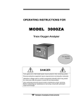
Series 4030
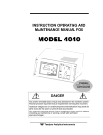
INSTRUCTION, OPERATING AND
MAINTENANCE MANUAL FOR
SERIES 4030 HEATED THC
TELEDYNE ANALYTICAL INSTRUMENTS
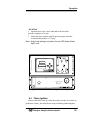
SPAN
SAMPLE
TEMP. GAUGE
SPAN GAS
BYPASS FLOW
DANGER
Toxic and/or flammable gases or liquids may be present in this monitoring system.
Personal protective equipment may be required when servicing this instrument.
Hazardous voltages exist on certain components internally which may persist for
a time even after the power is turned off and disconnected.
Only authorized personnel should conduct maintenance and/or servicing. Before
conducting any maintenance or servicing, consult with authorized
supervisor/manager.
P/N M77216
ECO: #XX-XXXX
DATE 12/13/05
Teledyne Analytical Instruments
Series 4030
Copyright © 2004 Teledyne Analytical Instruments
All Rights Reserved. No part of this manual may be reproduced, transmitted, transcribed,
stored in a retrieval system, or translated into any other language or computer language in
whole or in part, in any form or by any means, whether it be electronic, mechanical,
magnetic, optical, manual, or otherwise, without the prior written consent of Teledyne
Analytical Instruments, 16830 Chestnut Street, City of Industry, CA 91749-1580.
Warranty
This equipment is sold subject to the mutual agreement that it is warranted by us free from
defects of material and of construction, and that our liability shall be limited to replacing or
repairing at our factory (without charge, except for transportation), or at customer plant at
our option, any material or construction in which defects become apparent within one year
from the date of shipment, except in cases where quotations or acknowledgements provide
for a shorter period. Components manufactured by others bear the warranty of their
manufacturer. This warranty does not cover defects caused by wear, accident, misuse,
neglect or repairs other than those performed by Teledyne or an authorized service center.
We assume no liability for direct or indirect damages of any kind and the purchaser by the
acceptance of the equipment will assume all liability for any damage which may result from
its use or misuse.
We reserve the right to employ any suitable material in the manufacture of our apparatus,
and to make any alterations in the dimensions, shape or weight of any parts, in so far as
such alterations do not adversely affect our warranty.
Important Notice
This instrument provides measurement readings to its user, and serves as a tool by which
valuable data can be gathered. The information provided by the instrument may assist the user
in eliminating potential hazards caused by his process; however, it is essential that all
personnel involved in the use of the instrument or its interface be properly trained in the
process being measured, as well as all instrumentation related to it.
The safety of personnel is ultimately the responsibility of those who control process
conditions. While this instrument may be able to provide early warning of imminent
danger, it has no control over process conditions, and it can be misused. In particular, any
alarm or control systems installed must be tested and understood, both as to how they
operate and as to how they can be defeated. Any safeguards required such as locks, labels,
or redundancy, must be provided by the user or specifically requested of Teledyne at the
time the order is placed.
Therefore, the purchaser must be aware of the hazardous process conditions. The purchaser
is responsible for the training of personnel, for providing hazard warning methods and
instrumentation per the appropriate standards, and for ensuring that hazard warning devices
and instrumentation are maintained and operated properly.
Teledyne Analytical Instruments, the manufacturer of this instrument, cannot accept
responsibility for conditions beyond its knowledge and control. No statement expressed or
implied by this document or any information disseminated by the manufacturer or its
agents, is to be construed as a warranty of adequate safety control under the user’s process
conditions.
Teledyne Analytical Instruments
Series 4030
Safety Messages
Your safety and the safety of others are very important. We have
provided many important safety messages in this manual. Please read
these messages carefully.
A safety message alerts you to potential hazards that could hurt you
or others. Each safety message is associated with a safety alert symbol.
These symbols are found in the manual and inside the instrument. The
definition of these symbols is described below:
GENERAL WARNING/CAUTION: Refer to the
instructions for details on the specific danger. These
cautions warn of specific procedures which if not
followed could cause bodily Injury and/or damage the
instrument.
CAUTION: HOT SURFACE WARNING: This warning is
specific to heated components within the instrument.
Failure to heed the warning could result in serious burns
to skin and underlying tissue.
WARNING: ELECTRICAL SHOCK HAZARD: Dangerous
voltages appear within this instrument. This warning is
specific to an electrical hazard existing at or nearby the
component or procedure under discussion. Failure to heed
this warning could result in injury and/or death from
electrocution.
Technician Symbol: All operations marked with this
symbol are to be performed by qualified maintenance
personnel only.
NOTE: Additional information and comments regarding
No
a specific component or procedure are highlighted in the
Symbol
form of a note.
STAND-BY: This symbol indicates that the instrument is
on Stand-by but circuits are active.
Teledyne Analytical Instruments
i
Series 4030
CAUTION:
THE ANALYZER SHOULD ONLY BE USED FOR THE
PURPOSE AND IN THE MANNER DESCRIBED IN
THIS MANUAL.
IF YOU USE THE ANALYZER IN A MANNER OTHER
THAN THAT FOR WHICH IT WAS INTENDED,
UNPREDICTABLE BEHAVIOR COULD RESULT
POSSIBLY ACCOMPANIED WITH HAZARDOUS
CONSEQUENCES.
This manual provides information designed to guide you through the
installation, calibration and operation of your new analyzer. Please read
this manual and keep it available.
Occasionally, some instruments are customized for a particular
application or features and/or options added per customer requests.
Please check the front of this manual for any additional information in
the form of an Addendum which discusses specific information,
procedures, cautions and warnings that may be specific to your
instrument.
Manuals do get misplaced. Additional manuals can be obtained from
Teledyne at the address given in the Appendix. Some of our manuals are
available in electronic form via the internet. Please visit our website at:
www.teledyne-ai.com.
Teledyne Analytical Instruments
ii
Series 4030
Additional Safety Information
DANGER
COMBUSTIBLE GAS USAGE
WARNING
This is a general purpose instrument designed for usage in a
non-hazardous area. It is the customer's responsibility to
ensure safety especially when combustible gases are being
analyzed since the potential of gas leaks always exist.
The customer should ensure that the principles of operating
of this equipment are well understood by the user. Misuse of
this product in any manner, tampering with its components,
or unauthorized substitution of any component may
adversely affect the safety of this instrument.
Since the use of this instrument is beyond the control of
Teledyne, no responsibility by Teledyne, its affiliates, and
agents for damage or injury from misuse or neglect of this
equipment is implied or assumed.
WARNING:
HYDROGEN GAS IS USED IN THIS INSTRUMENT AS
A FUEL. HYDROGEN IS EXTREMELY FLAMMABLE.
EXTREME CARE MUST BE USED WHEN WORKING
AROUND GAS MIXTURES CONTAINING
FLAMMABLE GASES.
A Successful leak check was performed at TI/AI on
the sample system of this instrument prior to
calibration, testing and shipping. Ensure that there
are no leaks in the fuel supply lines before applying
power to the system.
Always purge the entire system before performing
any maintenance and always leak check the system
after removing any tubing or fittings on the sample
Teledyne Analytical Instruments
iii
Series 4030
system. See the procedures for purging and leak
checking this instrument on the following pages.
If toxic gases or other hazardous materials are
introduced into the sample system, the same
precautions regarding leak checking and purging
apply to the sample lines and sample supply or
delivery lines.
WARNING:
ELECTRICAL SHOCK HAZARD. WITH THE
EXCEPTION OF OPENING THE DOOR AND
ADJUSTING THE PRESSURE REGULATORS, FLOW
CONTROLLER, OR OBSERVING THE PRESSURE
GAUGES AND THE FLOWMETER, ONLY
AUTHORIZED AND SUITABLY TRAINED
PERSONNEL SHOULD PERFORM WORK INSIDE OF
THE INSTRUMENT. COMPONENTS WITHIN THE
COVER ON THE INSIDE OF THE DOOR, INSIDE THE
ISOTHERMAL CHAMBER (SAMPLE SYSTEM), AND
ON THE ELECTROMETER-AMPLIFIER PC BOARD
CONTAIN DANGEROUSLY HIGH VOLTAGE
SUFFICIENT TO CAUSE SERIOUS INJURY OR
DEATH.
There are the following three types of inaccessible
shock hazards within the Analyzer:
1. Line voltages and line related voltages such as
115 VAC which exists within the 230 VAC
versions as well. These voltages stop when the
Analyzer is turned off and the mains (line) cord is
removed from the instrument.
2. The sensor anode supply voltage (approximately
250 VDC). This voltage exists on the Flame
Guard, anode power supply, PCB, the
motherboard, and the anode/igniter terminals on
the sensor. THIS VOLTAGE WILL REMAIN
HAZARDOUS FOR MANY MINUTES AFTER THE
ANALYZER HAS BEEN TURNED OFF!
3. External hazardous voltages which may be
connected to the Analyzer alarm relay
connections.
Teledyne Analytical Instruments
iv
Series 4030
Procedure for Removal of Internal Inaccessible
Shock Hazards
CAUTION:
SERVICING OR MAINTENANCE OF THE ANALYZER
SHOULD ONLY BE DONE BY SUITABLE TRAINED
PERSONNEL. TO AVOID THESE INACCESSIBLE
HAZARDOUS VOLTAGES WHEN SERVICING THE
SERIES 4060, PERFORM EACH OF THE FOLLOWING
STEPS, IN THE ORDER GIVEN, BEFORE SERVICING
BEGINS:
Switch off the power to the Analyzer and remove the main (line)
power cord from the Analyzer.
Remove all external voltages from the connections to the alarm
contacts.
Wait one minute.
Discharge the anode supply voltage.
a. Connect one end of an insulated (to 1000 VDC or more)
clip lead to Analyzer chassis ground (the standoff for the
upper right corner of the mother PCB).
b. Put one end of a 500V rated 1000 ohm resistor in the
other end of the clip lead.
c. Check the voltage between chassis ground (the standoff
for the upper right corner of the mother PCB) and the top
side of R2 at PCB number B74671. It should be between
-5VDC and +5VDC. If is in that range, the inaccessible
hazardous voltage removal procedure is completed, if not
repeat steps 4.a and 4.b.
If it is absolutely necessary to work inside the instrument with power
on, use the ONE HAND RULE:
Work with one hand only.
Keep the other hand free without contacting any other object. This
reduces the possibility of a ground path through the body in case of
accidental contact with hazardous voltages.
WARNING:
THIS INSTRUMENT IS DESIGNED TO BE OPERATED
IN A NONHAZARDOUS AREA. THE ANALYZER USES
HYDROGEN GAS AND/OR OTHER COMBUSTIBLE
GASES IN ITS OPERATION. THIS EQUIPMENT, IF
NOT USED AND MAINTAINED PROPERLY CAN BE
AN EXPLOSION HAZARD. THE ANALYZER,
Teledyne Analytical Instruments
v
Series 4030
DEPENDING ON THE APPLICATION, MAY ALSO USE
TOXIC GASES. IT IS THEREFORE, THE
CUSTOMER'S RESPONSIBILITY TO ENSURE THAT
PROPER TRAINING AND UNDERSTANDING OF THE
PRINCIPLES OF OPERATION OF THIS EQUIPMENT
ARE UNDERSTOOD BY THE USER. SINCE THE USE
OF THIS INSTRUMENT IS BEYOND THE CONTROL
OF TELEDYNE, NO RESPONSIBILITY BY TELEDYNE,
ITS AFFILIATES AND AGENTS FOR DAMAGE OR
INJURY RESULTING FROM MISUSE OR NEGLECT
OF THIS INSTRUMENT IS IMPLIED OR ASSUMED.
MISUSE OF THIS PRODUCT IN ANY MANNER,
TAMPERING WITH ITS COMPONENTS OR
UNAUTHORIZED SUBSTITUTION OF ANY
COMPONENT MAY ADVERSELY AFFECT THE
SAFETY OF THIS INSTRUMENT.
CAUTION:
WHEN OPERATING THIS INSTRUMENT, THE DOORS
MUST BE CLOSED AND ALL COVERS SECURELY
FASTENED. THE GAUGES MUST BE IN PROPER
WORKING ORDER. DO NOT OVERPRESSURIZE THE
SYSTEM.
READ THIS MANUAL BEFORE OPERATING THE
INSTRUMENT AND ADHERE TO ALL WARNINGS
INCLUDED IN THIS MANUAL.
Teledyne Analytical Instruments
vi
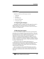
Introduction
Introduction
Teledyne Analytical Instruments Series 4030 Total Hydrocarbon
(THC) Analyzer is designed to measure the quantity of hydrocarbons
present in a heated sample gas, such as gaseous mixtures or ambient air
in various industrial applications. The Analyzer is a microprocessor
controlled digital instrument based on Teledyne’s highly successful
Model 402R series Total Hydrocarbon Analyzer, coupled with carrier
gas, a switching valve and a sample draw pump (optional). This allows
for the sample into the Sample Loop kept inside a heated SAMPLE
CHAMBER and maintained at a constant temperature in the range of 50
to 120 C as per application. With a 2-position, 10 port switching valve
and Carrier Gas, the sample collected inside the Sample Loop is pushed
inside the Flame Ionization Detector (FID) and analyzed for the THC.
The sample integrity, as it enters the Analyzer, is maintained by
ensuring that condensation does not take place inside the SAMPLE
CHAMER. This is ensured by maintaining a high temperature (50 80°C typical) inside the SAMPLE CHAMBER. Also, the sample is
diluted with the Carrier Gas to ensure that once the mixed sample
reached FID, no further condensation takes place.
A separate SAMPLE SELECTOR MODULE unit (optional) may be
provided for use in conjunction with the Model 4030. This allows the
User to bring the heated Sample gas (Max: 120 C) and the Span gas to
the Sample Selector Unit and manually select either Sample or Span for
entry into the Model 4030. The User is responsible for making all gas
connections from the Sample point to the Sample Selector Unit and also
between Sample Selector Unit and Model 4030. The User must also
ensure that gases are heated above the dew point (Max: temp. allowed
120 C) and are cleaned to better than 2 micron filter.
1.1 Main Features of the Analyzer
The Analyzer is sophisticated yet simple to use. A dual display on
the front panel prompts and informs the operator during all phases of
operation. The main features of the analyzer include:
1. Easy-to-use front panel interface that includes a red 5-digit LED
display and a vacuum fluorescent display (VFD), driven by
microprocessor electronics.
Teledyne Analytical Instruments
7
Introduction
2. High resolution, accurate readings of concentration.
3. Versatile analysis with three user-definable analysis ranges.
4. Microprocessor based electronics: 8-bit CMOS microprocessor
with 32 KB RAM and 128 KB ROM.
5. Auto ranging allows analyzer to automatically select the proper
preset range for a given measurement. Manual override allows
the user to lock onto a specific range of interest.
6. Two adjustable concentration alarms and a system failure alarm.
7. Extensive self-diagnostic testing at startup and on demand.
8. RS-232 serial digital port for use with a computer or other digital
communication device.
9. Analog outputs for selectable concentration, analog input
waveform and range identification (0-1 VDC standard and
isolated 4-20 mA dc).
10. Superior Accuracy
1.2 Principle of Operation
The sample is brought to a heated SAMPLE CHAMBER (50 - 120°
C per application) and into a sample loop and a 10-port, 2 position
(Position A & B) switching valve. The carrier gas, typically nitrogen,
pushes the sample alternatively from each sample loop into the FID to
detect the hydrocarbons.
1.3 Analyzer Description
The standard analyzer is housed in a sheet steel equipment case
flush-mounted in a 19" rack. The front interface panel is mounted on a
door which, when opened, allows convenient access to the Analyzer
electronics. The entire front panel can slide out of the chassis to provide
greater access to the electronics and to the sample system. Gas pressure
and flow controls are mounted on the front panel adjacent to the LED
and VFD displays and user interface.
At the rear of the instrument are ports for the introduction of air,
carrier, fuel, span, and sample gas. A single 50-pin user-interface cable
connector contains input/output and alarm signals available to the user.
An RS-232 port is also available at the rear panel for connection to a
remote computer or other digital communication device. The Analyzer is
set up for either 120 VAC 60 Hz or 230 50/60Hz operations depending
Teledyne Analytical Instruments
8
Introduction
on the customer’s requirements. The appropriate power cord for your
unit has been shipped with this instrument.
1.4 Applications
. Monitoring the ambient air for Total Hydrocarbons in chemical and
petrochemical plants.
. Fugitive emission monitoring.
. Process emission gases in the chemical industry.
2.1 Introduction
Using a built-in pump, the heated Sample from the Sample Selector
Unit is brought to the heated SAMPLE CHAMBER of Model 4030,
housing filter cartridge, switching valve and sample loops. Using
nitrogen carrier gas and the microprocessor actuated switching valve, a
fixed volume of sample, which is collected in Sample Loop, is pushed
into the FID detector.
Series 4030 uses a Flame Ionization Detector to sense hydrocarbons.
The FID was selected based on the positive performance and extensive
experience in the use of this detector in other Teledyne analyzers namely
Model 402R and Model 4020. The FID has proven itself to be a rugged,
stable, long life sensor giving years of trouble free operation in various
applications.
Typically, Model 4030 is calibrated using a known mixture of
methane in air, and thus the THC is shown as equivalent ppm methane
concentration.
A separate SAMPLE SELECTOR MODULE Unit (optional) may be
provided with a heated chamber (120 C Typical) and a manual 3- way
valve. This allows the User to connect Sample gas and the Span gas to
the back of the Sample Selector Unit and manually select the gas to
Model 4030 for analysis. The User must ensure that the Sample gas is
kept above the dew point to avoid condensation from the Sample point
to its entry into Model 4030.
Teledyne Analytical Instruments
9
Introduction
The Series 4030 Analyzer is composed of three subsystems:
1. Sample System
2. Detector Cell
3. Electronic Signal Processing, Display and Control
2.2 Sample System
The Analyzer contains two (2) separate isothermal chambers
controlled by individual PID temperature controllers, viewed just behind
the Front Panel. The three chambers, ‘SAMPLE’ and ‘FID are
described below.
The Analyzer consists of a SAMPLE CHAMBER containing the 10port switching valve and 2 sample loops. A sample filter with
replaceable filter cartridge is also included inside the Sample Chamber.
The Analyzer also consists of an ‘FID’ chamber containing the Flame,
pressure regulators, pressure gauges and flow restrictors.
2.2.1 Input Porting
The Analyzer is equipped with ports for the introduction of air, fuel,
carrier gas and sample gas. It is imperative that these gases are
supplied at constant pressures using two stage stainless steel diaphragm
gas regulators. The recommended pressure range is 30 to 60 psig.
Teledyne Analytical Instruments
10
Introduction
2.2.2 Gas Flow Control System
The Piping diagram is in the rear of this manual. A 10 port-switching
valve is used to control and direct gas flows to the FID detector. The
fixed volume sample loop ensures the same volume of sample injection
in the Analyzer every cycle.
2.2.3 Fuel and Blanket Air Systems
Stable flow is achieved by maintaining a constant pressure across
restrictors upstream from the cell. Each system incorporates an adjustable
pressure regulator, pressure gauge, and restrictor. A flame out light is
included to indicate when the flame fails. A fuel shut-off solenoid valve,
mounted on the line that supplies fuel, stops the fuel flow in case of flame
failure. This valve is located in line with the fuel port.
2.2.4 Flame Ionization Detection Cell
The carrier gas containing sample and fuel are combined within a tee
fitting located in the isothermal chamber. The mixed gas is emitted from
a burner within the sensor assembly. Blanket air is introduced into the
sensor (or cell) by means of a separate fitting that is located in the base
section of the assembly. The upper half of the assembly houses the
anode-igniter, collector, and flame guard thermistor.
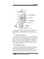
2.3 Detection Cell
The upper section of the stainless steel flame ionization cell houses
the cylindrical collector electrode, the high voltage (+260 VDC) anodeigniter coil, and the sensing thermistor of the flame guard circuit (see
cell cross-section Figure 2-1).
WARNING:
DANGEROUS HIGH VOLTAGE EXISTS AT THE
ANODE IGNITER COIL (+260 VDC). DO NOT
ATTEMPT TO DISCONNECT THE IGNITER COIL
CABLE OR DISASSEMBLE ANY OF THE FLAME
IONIZATION CELL COMPONENTS WITHOUT
TURNING OFF THE POWER AND DISCONNECTING
THE POWER CORD.
The collector is interconnected with the electrometer-amplifier PC
board by a coaxial cable. Although the cable and fittings are intended for
coaxial service, the cable is actually being used as a shielded singleconductor connection.
Teledyne Analytical Instruments
11
Introduction
The anode-igniter, as its name implies, serves two functions. When
relay K2 at PCB part number B74671 is energized, the coil becomes an
electrical heating element that glows red-hot and ignites the hydrogen
fuel. When relay K2 at B74671 is de-energized, the coil is connected to
the +260 volt DC terminal of the anode-flame guard power supply PC
board. In this configuration, the necessary potential difference is
established between the coil (anode) and collector to promote ionization
of the burned hydrocarbons. The coil functions as the high voltage anode
in all three-range positions of the selector switch.
The thermistor acts as the sensor in the flame guard circuit. Its
ambient temperature resistance is in the 100 K ohms region. When the
flame is ignited, its resistance is reduced by a factor of 100. The
thermistor is coupled to a semiconductor control circuit on the anodeflame guard power supply PC board, which will be described in a
following section.
The cell electrodes of both the anode-igniter and flame guard
thermistor are connected to the electronics chassis by means of a plug-in
cable.
Teledyne Analytical Instruments
12
Introduction
Figure 2-1: Flame Ionization Cell
The electrode section of the cell may be removed for inspection by
turning off the power, disconnecting the electrode lead plug, and
removing the screws, which retain the electrode assembly in the sensor
body.
2.3.1 Electrometer-Amplifier
The collector cable is coupled directly to a coaxial fitting located on
the electrometer-amplifier PC board. The PC board is located on the side
panel next to but outside of the isothermal chamber. See Figure 2-1 and
consists of an electrometer amplifier and an operational amplifier. This
circuit is a very high-gain, current-to-voltage converter circuit, having
an input impedance measuring in the billions of ohms. It is static
sensitive and highly susceptible to contamination. Special care must be
taken in handling this PC board.
2.3.2 Anode Power Supply
The high voltage anode power supply components are mounted on
the anode power supply printed circuit board. High voltage regulation is
achieved through the use of series-connected zener diodes. The
simplicity of this circuit’s design can be attributed to the extremely low
current demand of the anode circuit. The positive output voltage is
Teledyne Analytical Instruments
13
Introduction
nominally 125 volts. Output tolerance is ±10 volts from the specified
125 volts.
2.3.3 Flame Guard Circuit
A thermistor-controlled, transistorized switching circuit is employed
to operate a relay in the event of a flameout condition. A panel indicator
light and fuel shut-off solenoid valve are operated by the relay to alarm
personnel that a flameout condition has occurred. The fuel shut-off
solenoid valve stops the hydrogen flow.
2.3.4 Flame Ignition Circuit
The flame ignition circuit includes the anode-igniter electrode (in the
detector cell), a transformer, and processor-controlled relay. The circuit
is automatically energized when the FID cools due to lack of flame.
If automatic ignition fails five times, there will be a message that
reports this, and the flame can be manually ignited by pressing
simultaneously the Up and Down key.
Teledyne Analytical Instruments
14
Installation
Installation
Installation of the Series 4030 Analyzer includes:
1. Unpacking
2. Mounting
3. Gas connections
4. Electrical connections
5. Testing the system.
3.1 Unpacking the Analyzer
Although the Analyzer is shipped with all the materials you need to
install and prepare the system for operation. Carefully unpack the
Analyzer and inspect it for damage. Immediately report any damage or
shortages to the shipping agent.
3.2 Mounting the Analyzer
The Series 4030 and the Sample Selector Unit are general-purpose
units and as such are designed with (non-sealed) enclosures. They must
be installed in an area where the ambient temperature is not permitted to
drop below 40ºF nor rise above 100ºF. In areas outside these
temperatures, auxiliary heating/cooling must be supplied. The 4030
enclosure is oil and dust resistant and although it is designed to resist
moisture, it should NOT be considered completely watertight. Mounting
to walls or racks must be made securely. Avoid locations that are subject
to extreme vibration and sway.
Sufficient space must be provided around the analyzers to
accommodate the necessary electrical conduit and plumbing connections.
The front panel must be allowed to be pulled out for possible service
access to all components of the enclosure. Refer to the system/analyzer
outline drawings for dimensions.
Note: To completely slide the Model 4030 Analyzer out of the
enclosure, pull Analyzer out until it stops, and then push down on the
release levers found almost at the end of the sliders, both sides at the
same time.
Teledyne Analytical Instruments
15
Installation
Regardless of configuration, the analyzer/system must be installed
on a level surface with sufficient space allocated on either side for
personnel and test equipment access. Subject to the foregoing, the
Analyzer/system should be placed as close to the sample point as is
possible.
All pertinent dimensions, connecting points, and piping details can
be found in the drawings section as part of the outline, input-output, and
piping diagrams. These drawings are specific to the instrument or
system to which the manual applies.
3.3 User Connections
All user connections are made on the rear panel. Consult the inputoutput and outline diagrams in the drawing section of the manual. Not
all the features displayed may be present in your system. Refer to any
Addenda for additional information that may apply to your instrument.
3.3.1 Electrical Power Connections
The standard analyzer requires a supply of 100-125VAC, singlephase power. Power connections are made at the rear panel of the unit.
Refer to the input-output diagram for more information. The electrical
power service must include a high-quality ground wire. A high-quality
ground wire is a wire that has zero potential difference when measured
to the power line neutral. If you have the 220 VAC option, you will
require 220 or 240 VAC, 50/60 Hz power. Check the analyzer inputoutput diagram, power schematic, outline, and wiring diagrams for
incoming power specifications and connecting points.
CAUTION:
PRIMARY POWER TO THE SYSTEM SHOULD NOT
BE SUPPLIED UNTIL ALL CUSTOMERS WIRING IS
INSPECTED PROPERLY BY START-UP PERSONNEL.
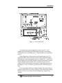
3.3.2 Gas Connections
The analyzer gas connection diagram identifies the various gas
connection points as to function and location. Figure 3-1 shows the gas
connection points for Model 4030 and SAMPLE SELECTOR
MODULE (optional).
Teledyne Analytical Instruments
16
Installation
Figure 3-1: Gas Connections
Gas connections to the instrument are made at the 1/8”or 1/4”
stainless steel tube fittings provided on the rear panel. Note that the
Purge and Sensor Vent fittings are 1/4” while all other gas connections
are 1/8”.
If the Sample line is heat traced to avoid condensation, the User
must ensure that a clean (2 micron or better filter) and heated sample,
maintained at a constant temperature not exceeding 120 C, is delivered
to the Sample Selector Module and the connection between the Sample
Selector Module and the Model 4030 is similarly heat traced. The
Sample Selector Unit contains provisions to accept tubing diameter in
the range of 1.25 to 1.50 inches, typically the O.D. of the heat-traced
lines.
It is recommended that all gas tubing leading to the connections on
the back of the analyzer be of the coiled type. This will facilitate sliding
the unit out of the case without disconnecting the gas supply to the
analyzer.
Teledyne Analytical Instruments
17
Installation
Before tubing is connected to the system, it must be decontaminated
to rid it of hydrocarbon deposits. Using a small torch, heat each length
of tubing, while passing nitrogen through it, until it glows red. Begin at
the nitrogen source end and proceed down the length of the tube,
“chasing” the red glow (and hydrocarbon deposits) down to the open
end of the tube. Cap tubing while not in use with suitable noncontaminating caps.
All sample, calibration, and supporting gas lines, which deliver gas
to the analyzer, must be decontaminated before connection; vent lines do
not.
When connecting the various gas lines to the system, be absolutely
certain that no “dead ends” are left; that is, no unused branch lines
should be left capped off, where pockets might form of material that is
not representative of the current contents of the line, or which might
keep contaminants from being purged out of the system.
CAUTION: THE GASES USED MUST BE OF THE
HIGHEST QUALITY, ULTRA ZERO GRADES, AS SHOWN
BELOW. FAILURE TO DO SO WILL RESULT IN
CONTAMINATION AND FAILURE TO DETECT LOW
CONCENTRATIONS OF HYDROCARBONS.AIR: USE ULTRA ZERO GRADE, WATER PUMPED, AIR WITH
THC LESS THAN 0.1 PPM.
FUEL: USE ULTRA HIGH PURITY (UHP) GRADE HYDROGEN
GAS, 100%, WITH THC LESS THAN 0.5 PPM.
CARRIER GAS: USE ULTRA HIGH PURITY GRADE
NITROGEN GAS, WITH THC LESS THAN 0.1 PPM.
3.3.3 Electrical Connections
Figure 3-1 shows the Series 4030 rear panel. There are connections
for power, digital communications, and both digital and analog
concentration output.
For safe connections, no uninsulated wiring should be able to come
in contact with fingers, tools or clothing during normal operation.
CAUTION:
USE SHIELDED CABLES. ALSO, USE PLUGS THAT
PROVIDE EXCELLENT EMI/RFI PROTECTION. THE
PLUG CASE MUST BE CONNECTED TO THE CABLE
SHIELD, AND IT MUST BE TIGHTLY FASTENED TO
Teledyne Analytical Instruments
18
Installation
THE ANALYZER WITH ITS FASTENING SCREWS.
ULTIMATELY, IT IS THE INSTALLER WHO ENSURES
THAT THE CONNECTIONS PROVIDE ADEQUATE
EMI/RFI SIELDING.
3.3.3.1 PRIMARY INPUT POWER
The power cord receptacle and fuse block are located in the same
assembly. Insert the power cord into the power cord receptacle.
CAUTION:
POWER IS APPLIED TO THE INSTRUMENT'S
CIRCUITRY AS LONG AS THE INSTRUMENT IS
CONNECTED TO THE POWER SOURCE.
The standard power supply requires 110 VAC, 50/60 Hz or 220
VAC, 50/60 Hz (optional) power.
3.3.3.2 FUSE INSTALLATION
The fuse block, at the right of the power cord receptacle, accepts US
or European size fuses. A jumper replaces the fuse in whichever fuse
receptacle is not used.
3.3.3.3 50-PIN EQUIPMENT INTERFACE CONNECTOR
Figure 3-2 shows the pin layout of the Equipment Interface
connector. The arrangement is shown as seen when the viewer faces the
rear panel of the analyzer. The pin numbers for each input/output
function are given where each function is described in the paragraphs
below.
Figure 3-2: Equipment Interface Connector Pin Arrangement
3.3.3.4 ANALOG OUTPUT
There are four DC output signal pins—two pins per output. For
polarity, see Table 3-1. The outputs are 0-1 VDC, 0-1 VDC, 4-20mA
DC, and 4-20mA DC.
The 1st and 3rd outputs (0-1 VDC, and 4-20mA DC) operate
analogously as do the 2nd and 4th outputs (0-1 VDC, and 4-20mA DC).
Teledyne Analytical Instruments
19
Installation
Both the first and third set of outputs as well as the second and
fourth set of outputs may be set to any of the following functions:
- THC -- Total hydrocarbon as measured in the first phase
of detection. The output is the percentage of the selected
range.
- SMP -- An alternate measurement that occurs during the
second phase of detection. The output represents the
percentage of the selected range.
- WAVE – Analogous to the continuous output of the FID.
- RID – Indicates the selected range. Low Range is at 1/5
of maximum output. Mid Range is at 1/2 of maximum
output. High Range is 4/5 of maximum output.
Table 3-1: Analog Output Connections
Pin
3
4
5
6
8
23
24
7
Function
Channel 2, + 4-20 mA, floating
Channel 2, – 4-20 mA, floating
Channel 1, + 4-20 mA, floating
Channel 1, – 4-20 mA, floating
Channel 2, 0-1 VDC
Channel 2, 0-1 VDC
Channel 1, 0-1 VDC
Channel 1, negative ground
Teledyne Analytical Instruments
20
Installation
3.3.3.5 ALARM RELAYS
The nine alarm-circuit connector pins connect to the internal alarm
relay contacts. Each set of three pins provides one set of Form C relay
contacts. Each relay has both normally open and normally closed contact
connections. The contact connections are shown in Table 3-4. They are
capable of switching up to 3 amperes at 250 VAC into a resistive load.
The connectors are:
Threshold Alarm 1:
Can be configured as high (actuates when concentration is above
threshold), or low (actuates when concentration is below
threshold).
Can be configured as failsafe or non-failsafe
Configured as latching or non-latching
Can be configured out (defeated).
Threshold Alarm 2:
Can be configured as high (actuates when concentration is above
threshold), or low (actuates when concentration is below
threshold).
System Alarm:
Actuates when power is removed from analyzer.
It is triggered if 4030 fails to ignite after five times.
The System Alarm may be reset by selecting the
STANDBY function in the menu to send to sleep mode,
then press the ENTER or ESCAPE key to restart the
analyzer. However, if the condition that caused the 4030 to
fail ignition is not remedied, the 4030 will likely fail to
ignite again, and the System Alarm will be re-triggered.
Further detail on flame ignition failure can be found in Chapter 4,
Section 4.3.1.
Teledyne Analytical Instruments
21
Installation
Table 3-2: Alarm Relay Contact Pins
Pin
45
28
46
42
44
43
36
20
37
Contact
Threshold Alarm 1, normally closed contact
Threshold Alarm 1, moving contact
Threshold Alarm 1, normally open contact
Threshold Alarm 2, normally closed contact
Threshold Alarm 2, moving contact
Threshold Alarm 2, normally open contact
System Alarm, normally closed contact
System Alarm, moving contact
System Alarm, normally open contact
3.3.3.6 RANGE ID RELAYS
There are three dedicated Range ID relay contacts. They are
assigned to relays in ascending order—Low range is assigned to Range
1 ID, Medium range is assigned to Range 2 ID, and High range is
assigned to Range 3 ID. Table 3-6 lists the pin connections. Contacts
are normally open, and they close when 4040 switches to that particular
range.
Table 3-3: Range ID Relay Connections
Pin
Function
21
Range 1 ID Contact
38
Range 1 ID Contact
22
Range 2 ID Contact
39
Range 2 ID Contact
19
Range 3 ID Contact
18
Range 3 ID Contact
34
Not Used
35
Not Used
Teledyne Analytical Instruments
22
Installation
3.3.3.7 NETWORK I/O
A serial digital input/output for local network protocol. At this
printing, this port is not yet functional. It is to be used in future options
to the instrument. Pins 13 (+) and 29 (–).
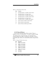
3.3.3.8 Pin Out Table
The following table summarizes all the outputs/inputs available in
the 50-pin D-Sub connector on the back panel of the Analyzer.
Table 3-4: Pin out of 50 pins D-Sub Connector
Pin #
Description
1
2
3
4
5
6
7
8
9
10
11
12
13
14
15
16
17
18
19
20
21
22
23
24
25
26
27
28
29
+ Output 4-20 ma, Channel 2, ID
- Output 4-20 ma, “, Range ID
+ Output 4-20 ma, Channel 1, %
- Output 4-20 ma, “, % Output
- Output 0-1 v (Channel 1)
+ Output 0-1 v (Channel 2)
Span Solenoid Return
Span Solenoid Hot
Range 3 Contact
Range 3 Contact
Alarm 3 C Contact
Range 1 Contact
Range 2 Contact
- Output 0-1 v (Channel 2)
+ Output 0-1 v (Channel 1)
Alarm 1 C Contact
Teledyne Analytical Instruments
23
Installation
30
31
32
33
34
35
36
37
38
39
40
41
42
43
44
45
46
47
48
49
50
Exhaust Solenoid Hot
Sample Solenoid Hot
Range 4 Contact/ not used
Range 4 Contact/not used
Alarm 3 NC Contact
Alarm 3 NO Contact
Range 1 Contact
Range 2 Contact
Alarm 2 NC Contact
Alarm 2 NO Contact
Alarm 2 C Contact
Alarm 1 NC Contact
Alarm 1 NO Contact
Exhaust Solenoid Return
Sample Solenoid Return
3.3.4 RS-232 Port
The digital signal output is a standard RS-232 serial communications
port used to connect the analyzer to a computer, terminal, or other digital
device. It requires a standard 9-pin D connector.
Input: The input functions using RS-232 that have been implemented
to date are described in Table 3-5.
Table 3-5: Commands via RS-232 Input
Command
Description
AS<enter>
immediately starts an auto span.
AL<enter>
immediately revert to Analyze (THC Phase)
RL<enter>
Change to Manual Range LOW
RM<enter>
Change to Manual Range MEDIUM
RH<enter>
Change to Manual Range HIGH
RA<enter>
Change to Manual Range AUTO
Teledyne Analytical Instruments
24
Installation
Implementation: The RS-232 protocol allows some flexibility in its
implementation. Table 3-6 lists certain RS-232 values that are required
by the Model 4030 implementation.
Table 3-6: Required RS-232 Options
Parameter
Setting
Baud
2400
Byte
8 bits
Parity
none
Stop Bits
Message Interval
1
Sent at the end of each cycle.
3.3.5 Supporting Gases
Normally, four supporting gases of different composition (see
Section 4.1: Equipment) will be required to operate the analyzer. The
recommended composition of these gases is specified in the Application
Data section of the Appendix. The gases should be supplied from
cylinders that are equipped with the type of regulator specified in the
aforementioned sections.
CAUTION:
UNDER NO CIRCUMSTANCES SHOULD YOU
EMPLOY A REGULATOR THAT IS NOT EQUIPPED
WITH A METALLIC DIAPHRAGM ANYWHERE IN THE
SYSTEM.
The regulators should be inspected prior to installation to be sure
that they are oil-free. Failure to comply with these directives will result
in a constant drift in analyzer output, as organic compounds will outgas
into the plumbing system at a rate that is related to the ambient
temperature. Use 316 stainless steel, dual-stage stainless steel diaphragm
regulators only in fuel, sample, and blanket air lines; shutoff valves
should be used downstream from each regulator.
Place the supply cylinders as close to the analyzer as possible, and
interconnect them to the analyzer with new tubing. Be sure that all
plumbing connections are free of leaks.
Note: Use only stainless steel tubing throughout the system.
Consult the assembly, piping, outline drawings, and any
Addenda included with this manual to determine if special
conditions apply.
Teledyne Analytical Instruments
25
Installation
CAUTION: THE GASES USED MUST BE OF THE
HIGHEST QUALITY, ULTRA ZERO GRADES, AS SHOWN
BELOW. FAILURE TO DO SO WILL RESULT IN
CONTAMINATION AND FAILURE TO DETECT LOW
CONCENTRATIONS OF HYDROCARBONS.
AIR: USE ULTRA ZERO GRADE AIR WITH THC LESS THAN
0.1 PPM. DO NOT USE OIL PUMPED AIR UNDER ANY
CIRCUMSTANCES.
FUEL: USE ULTRA HIGH PURITY (UHP) GRADE HYDROGEN
WITH THC LESS THAN 0.5 PPM.
CARRIER GAS: USE ULTRA HIGH PURITY GRADE
NITROGEN GAS, WITH THC LESS THAN 0.1 PPM.
3.3.5.2 EFFLUENT
All the gases introduced into the detection cell vent from one fitting
at the rear of the analyzer. TAI recommends that the cell be permitted to
vent directly to the atmosphere wherever possible.
If a vent line is required, the installation must include a drop-out pot
to collect the water that is formed by the burning of the hydrogen fuel.
The vent line must be constructed so that water and dirt cannot collect in
it.
3.3.5.3 SAMPLE BYPASS VENT
The sample bypassed by the back-pressure regulation system vents
from a separate port at the rear of the analyzer. If a vent line is required,
it must be installed so that water and dirt cannot accumulate in it.
3.3.5.4 FUEL AND AIR CONNECTIONS
The fuel used to provide combustion should be Hydrogen gas, zero
quality with certified THC of less than 0.5 ppm and a pressure of 30
psig. The compressed air, ultra zero gas quality with THC less than 0.1
ppm should be used at a controlled pressure of 30 psig Connect the fuel
and air sources to the instrument according to the gas connection
diagram included at the back of this manual.
Teledyne Analytical Instruments
26
Operation
Operation
4.1 Placing the System in Operation
1. Plug the power in the AC power inlet in the back of the Analyzer
and the Sample Selector Unit.
2. Allow at least 2 hours warm-up (heat up sensor & sample
system) after making the air adjustment described below. Warm
up time is set by the software at the factory but may be
overridden by pressing the <ENTER> key.
DO NOT attempt to ignite the flame during warm up
countdown. Condensation will occur.
4.2 Activating the Support Gases
4.2.1 Air
1. Set the air tank regulator to 30 psig.
2. Adjust the Analyzer Air regulator until the air pressure gauge
reads the recommended air pressure of 9 psig.
After the air is flowing through the sensor and warm-up time has
been completed, activate the following gases:
4.2.2 Carrier Gas
Set the Carrier gas tank regulator to 50 psig and adjust the Analyzer
Sample regulator until its (sample) pressure gauge reads the
recommended sample pressure of 9.5 psig.
4.2.3 Span Gas
The Span gas containing certified mixture of methane in
air, recommended range 6 to 8 ppm methane in zero grade
air, may be connected to the Span Manifold or the ¼ inch
connection on the back of the Sample Selector Module.
Teledyne Analytical Instruments
27
Operation
4.2.4 Fuel
1. Open the main valve on the tank and set the fuel tank
pressure regulator to 30 psig.
3. Adjust the Fuel regulator until its pressure gauge reads the
recommended pressure of 3.5 psig.
Note: Adjust fuel settings only when the red LED (flame failure
light) is off.
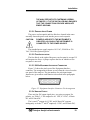
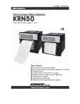
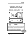
TELEDYNE ANALYTICAL INSTRUMENTS
SPAN
SAMPLE
TEMP. GAUGE
SPAN GAS
BYPASS FLOW
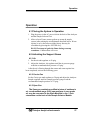
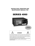
Figure 4-1: Front Panel View of Regulator and Gages
4.3 Flame Ignition
Observe that after warm up count down timer reaches zero (timer to
preheat the sensor), the amber heater lamp is blinking (indicating that
Teledyne Analytical Instruments
28
Operation
the temperature controller is maintaining the temperature set point) and
the red flame failure lamp is on. See Figure 4-1.
The Series 4030 will automatically attempt a flame ignition
sequence following the warm up period, which has been preset at the
factory. If the ignition process fails, the instrument will attempt to ignite
the flame 4 more times. If it continues to fail after the fifth attempt, a
flame failure message will appear on the display. If this occurs refer to
Section 4.3.1.
4.3.1 Verification of the Flame Guard Circuit
The operation of the flame guard circuit has been checked at the
factory, but should be re-verified during start-up. Use the following
procedure after ignition of the flame has been achieved:
1. Turn off the fuel at the supply cylinder.
2. Observe the fuel pressure gauge on the analyzer control panel. The
gauge indication will decay as the fuel in the line is exhausted.
When the gauge reading reaches the vicinity zero, the flame will
be extinguish as the fuel solenoid shuts off the fuel supply. The
analyzer will automatically try to re-ignite. After 5 attempts, it will
display: flame failure, check air, fuel and the flame failure LED
will be on.
3. Open the cylinder supply valve and re-ignite the flame by
pushing the UP and DOWN buttons simultaneously.
4.3.2 Ignition and/or Flame Guard Circuit Failure
If the flame ignition or guard circuits do not operate as described in
the above two sections, set the instrument fuel regulator to the
recommended pressure.
4.3.3 Sample Pump
A built-in Sample Pump is provided to draw Sample Gas from the
Sample line. The gas flow rate should be maintained at about 1000 to
1200 cc/minute using the Front Panel FLOW CONTROL valve
(clockwise increases flow).
4.4 Analyzer Operation
Although the Model 4030 has been programmed for your application
at the factory, it can be further configured at the operator level.
Teledyne Analytical Instruments
29
Operation
Depending on the specifics of the application, this might include all or a
set of the following procedures:
1. Setting system parameters
1. Establish a security password, if desired, requiring operator
to log in
2. Establish and start an automatic calibration cycle (not
available)
3. Choose auto ranging or select a fixed range of analysis
4. Set alarm set points and modes of alarm operation
5. Calibrate analog output, select analog output source.
2. Routine operation
1. Calibrate the instrument
Procedures for accessing and/or changing parameters as well as
analyzer operation are detailed in the sections to follow. In general, the
sequence of menus available on screen follows a logical course for setup
and operation. It is not required, however to follow this sequential path.
The user could, for instance, go directly to set an analysis range and then
program an offset to the current output for matching a range on the
user’s recording device. The only exception to this is when the
instrument is powered up. It will go through a warm-up period, followed
by a diagnostic self-test routine.
Teledyne Analytical Instruments
30
Operation
4.4.1 Default Parameters
The versatility of this analyzer usually results in significant changes
being made to parameters over the course of time to better suit a
particular application. Occasionally processes change requiring
alteration to alarms, ranges etc. At some time, it may be beneficial to
reset the analyzer to the default conditions as it was when shipped from
the factory. Below is a listing of the default parameters used in
configuring your instrument:
Range/Application: Refer to the data sheet on the first page of
this manual
Range: Auto
Alarms: Enabled, AL1=20ppm, AL2=50ppm, HI,
NON-FAILSAFE, NON-LATCHING,
THC levels
Auto Span Timing: Not available.
THC Span: 8 ppm methane in air.
Password: TAI
Analog Outputs: Ch1=THC levels
Ch2=Range ID
4.4.2 Style Conventions
The following typeface conventions are used when referring to
screen names, key presses and screen readout:
Screens:
Arial 12 pt. type in capital letters.
Example: ANALYZE or MAIN
screen or menu.
Key presses:
<key> The particular keystroke to
enter is placed between < and >.
Example: <enter> or <escape> or
<▲> (UP key) or <▼> (DOWN
key.
Only when the keystroke is to be
entered will it be placed between
the brackets. If discussing a
Teledyne Analytical Instruments
31
Operation
Screen Modes:
Screen Readout:
particular key it will be typed as
text using all caps. Example: this is
the ENTER key.
Times New Roman 12 pt. italic.
Example: Analysis Mode or Setup
Mode.
Arial Narrow, 12 pt bold.
Example: AUTOCAL or Zero in 12
days.
4.4.3 Navigation and Data Entry
Note: All menus time out after 15 (fifteen) seconds elapse with
no button presses, the analyzer returns to the ANALYSIS
SCREEN, if parameters have been altered but not saved
(with the ENTER key), the alterations are lost.
Navigation and Data Entry is possible using 2 ARROW KEYS, the
ENTER key, and the ESCAPE key. It is important to read and
understand the MENU STRUCTURE section to fully understand
navigation and data entry.
4.4.3.1 ARROW KEYS
Pressing the ARROW KEYS select menus and modifies values.
1. In the ANALYSIS SCREEN, the ARROW KEYS cause
entry into the MAIN MENU.
6. When the selected option is a function on the MAIN MENU
or any SUB MENU screen, the ARROW KEYS move to the
next lower or upper menu.
7. If the selected option is a MODIFIABLE ITEM (value is
flashing), The ARROW KEYS increment or decrement
numeric values or toggle ON/OFF, YES/NO, or
ENABLE/DISABLE type values.
4.4.3.2 ENTER
The ENTER key is used in several context-sensitive ways.
2. When showing the THC analysis mode, the ENTER key
toggles the LINE 2 display.
LINE 2 display mode 1 data:
- Current analysis mode
Teledyne Analytical Instruments
32
Operation
- Dynamic (real time) FID input level
- Time spent in mode
- Range
- Activity indicator
LINE 2 display mode 2 data:
- Current analysis mode
- Analysis TOTAL AREA from most recent pass of
current mode.
- Time spent in mode
- Range
- Activity Indicator
3. When the selected option is a function on the MAIN MENU
or any SUB MENU screen, the function name appears with
an arrow next to it. In some cases, the item in the menu is
the parent of another SUB MENU; in other cases, the item in
the menu is the parent of a MODIFIABLE ITEM.
8. If the selected option is a MODIFIABLE ITEM, the ARROW
KEYS are used to modify the value of the item. A modifiable
item is flashing. The ENTER key is then used to accept the
value and move you to the next field to continue programming.
4.4.3.3 ESCAPE
The ESCAPE key is used in several context-sensitive ways.
4. When showing the THC analysis mode, the ESCAPE key
temporarily clears any present alarms. However, if the alarm
condition is still present, the alarm will re-occur when redetected. Also, pressing the ESCAPE key clears the
messages generated by incorrect gain settings (i.e. bad span,
gain too high).
When the selected option is a function on the MAIN MENU
or any SUB MENU screen (the menu name appears with a
flashing arrow next to it), the ESCAPE key is used to return
to the parent menu finally returning to the ANALYSIS
SCREEN the function.
9. If the selected option is a modifiable item (value is flashing),
The ESCAPE key is used to escape to the parent menu without
Teledyne Analytical Instruments
33
Operation
saving the value. The value will revert to the original before
modification (if any).
4.4.4 Menu Structure
The 4030 screen setup consists of several classes of screens and
items. No item occupies more than 1 line. It is important to read and
understand the NAVIGATION AND DATA ENTRY section to fully
understand the menu structure.
The ANALYSIS SCREEN displays the following:
LINE 1:
- Analysis value of THC
- Alarms, if present, dashes if not ("AL –2" means alarm
2 has been triggered, "AL 1-" means alarm 1 has been
triggered, "AL 12" means both alarms have been triggered).
If in Span calibration, Alarm display is replaced with the
message "SPAN".
LINE 2 (display mode 1):
- Current analysis mode
- Dynamic (real time) FID input level
- Time spent in mode
- Range
- Activity indicator
LINE 2 (display mode 2):
- Current analysis mode
- Analysis TOTAL AREA from most recent pass of
current mode, identified by the units 'vS' – volt Seconds (the
alternate mode TOTAL AREA is shown while the ESCAPE
key is held down).
- Time spent in mode
- Range
- Activity Indicator
10. The MAIN MENU and SUB MENU screens have a flashing
arrow on the left side indicating which item is being pointed
to.
Teledyne Analytical Instruments
34
Operation
11. MODIFIABLE ITEM screens have a flashing value
somewhere in the line.
4.4.4.1 MAIN MENUS
The MAIN MENU consists of 13 functions you can use to customize
and check the operation of the analyzer. They are listed here with brief
descriptions:
1. AUTO-CAL: Used to define and/or start an automatic calibration
sequence. AUTOCAL is not available for standard
configurations of the 4030.
2. GAIN: Used to change the amplification of the incoming signal.
This is factory set, and should not change.
3. PASSWORD: Used to establish password protection or change
the existing password.
4. LOGOUT: Logging out prevents unauthorized tampering with the
analyzer settings.
5. MODEL: Displays Manufacturer, Model, and Software version of
the instrument.
6. SELF-TEST: The instrument performs a self-diagnostic routine to
check the integrity of the power supply, and output boards.
7. SPAN: Set up and/or start a span calibration
8. ALARMS: Used to set the alarm set points and determine whether
each alarm will be active or defeated, HI or LO acting, and
failsafe or not.
9. RANGE: Used to set up three analysis ranges that can be
switched automatically. With auto-ranging or used as individual
fixed ranges.
10. ANALOG-OUT ADJUST: Adjust the analog output with offset and
scaling for Channel 1 only.
11. CHANGE STREAM: Not available.
12. TIMING: Low-level application specific timing parameters.
Factory set. Do not change these.
13. STANDBY: Removes power to outputs and displays, but
maintains power to internal circuitry.
Any function can be selected at anytime. Just scroll through the
MAIN MENU with the DOWN/UP keys to the appropriate function, and
Teledyne Analytical Instruments
35
Operation
ENTER it. The analyzer will immediately start that function, unless
password restrictions have been assigned. (Password assignment is
explained in Section 4.4.10).
4.4.4.2 EXPANDED MENUS
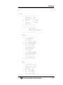
An exhaustive list of menu messages is provided as follows.
AUTOCAL
----------------------AUTO SPAN NOT AVAILABLE
-----------------------
AUTOCAL is not available for standard configurations of the
4030.
PASSWORD
----------------------Enter Password
'T' 'A' 'I'
----------------------GAIN ADJUST
----------------------GAIN 0
--------------------------------------------Password Incorrect
Change Password
--------------------------------------------Enter New Password
'T' 'A' 'I'
--------------------------------------------Reenter New Password
'A' 'A' 'A'
---------------------------------------------
Teledyne Analytical Instruments
36
Operation
Password Mismatch
----------------------Password Changed!
----------------------LOGOUT
----------------------Restrict Access?
ENTER-YES
ESCAPE-NO
----------------------MODEL
----------------------4030 THC Monitor
V1.0
----------------------SELF TEST
----------------------Begin Self-Test?
ENTER-YES
ESCAPE-NO
--------------------------------------------Running Diagnostic
5V
- Test
15V
- Test
DAC A - Test
DAC B - Test
--------------------------------------------Diagnostic Result
5V
- GOOD
15V
- GOOD
DAC A - GOOD
DAC B - GOOD
-----------------------
Teledyne Analytical Instruments
37
Operation
SPAN
----------------------THC Span ?:
Yes
SMP Span ?:
No
THC Sp:
8.00 ppm
SMP Sp:
0.00 ppm
Span Begin
--------------------------------------------Begin Span?
ENTER-YES
ESCAPE-NO
----------------------ALARMS
----------------------AL-1 DEFEATED
AL-1 HIGH
AL-1 NON-FAILSAFE
AL-1 NON-LATCHING
AL-1 20.00 ppm
AL-1 SOURCE THC
AL-2 DEFEATED
AL-2 HIGH
AL-2 NON-FAILSAFE
AL-2 NON-LATCHING
AL-2 50.00 ppm
AL-2 SOURCE THC
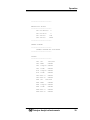
----------------------RANGE
----------------------Range Select: Auto
AutoRange Src: THC
Man Rng:
R1
R1: 0-10.00ppm
R2: 0-100.00ppm
R3: 0-1000.00ppm
Teledyne Analytical Instruments
38
Operation
----------------------ANALOG-OUT ADJUST
----------------------CH1 mA Offset:
0
CH1 mA Gain:
0
CH1 Select:
THC
CH2 Select:
WAVE
----------------------CHANGE STREAM
----------------------CHANGE STREAM NOT AVAILABLE
----------------------TIMING
----------------------THC I/P:
100%/00%
THC TIME:
05m00s
THC I Begin: 00m05s
THC I End:
00m05s
AIR I Begin: 00m05s
AIR I End:
00m05s
THC Base 1:
00m03s
THC Base 2:
00m03s
SMP I/P:
100%/00%
SMP TIME:
05m00s
SMP I Begin: 00m05s
SMP I End:
00m30s
SMP Base 1:
00m03s
SMP Base 2:
00m03s
Teledyne Analytical Instruments
39
Operation
----------------------STANDBY
Switch to Sleep Mode
ENTER-YES
ESCAPE-NO
notification if logged out
----------------------Access Restricted
Re-enter Password
-----------------------
4.4.5 Setting up an AUTO-CAL
AUTOCAL is not available for standard configurations of the
4040.
4.4.6 Adjusting the GAIN
The output of the FID is conditioned by an amplification circuit with
3 user-adjustable settings:
0) x1
1) x10
2) x100
The resulting signal is converted to a number. Numbers outside the
range –262144 to 262143 are unreliable and lead to inaccurate
measurements. If the number is outside this range during analysis, the
message 'GAIN TOO HIGH' is shown on the 2nd line of the display, and
the analyzer is not updated to a new, calculated value. The Gain Too
High message may be removed by pressing the ESCAPE key.
The gain has been set at the factory such that the analyzer will work
reliably within the prescribed range of operation. The user may change
the gain when a different level of sample is to be analyzed.
Teledyne Analytical Instruments
40
Operation
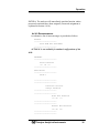
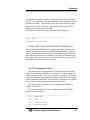
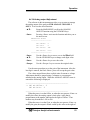
To setup the GAIN:
1) From the Analysis Screen, press an arrow key to enter the Setup
Mode. The VFD will display the first 2 lines of functions available.
________________________________________________
-> GAIN ADJUST
PASSWORD
________________________________________________
<▲▼>
If the arrow is not adjacent to the GAIN ADJUST menu
item, use the ▲▼ keys to move the arrow to the proper
position.
<Enter>
Press <Enter> to activate the function and move you to
the next screen.
________________________________________________
-> GAIN 1
________________________________________________
Note, for instruction on how to, please refer to the section 4.4.3
Navigation and Data Entry.
In the example, the number to the right of the word 'GAIN' is 1,
this reflects a gain of x10.
4.4.6 Password Protection
Before a unique password is assigned, the system assigns TAI by
default. If the password is the default, it will be displayed automatically.
The operator just presses <Enter> from the any of the MAIN MENU
items to be allowed access to that item's sub menu. If the password has
previously been changed from the default then the initial display will be
'A' 'A' 'A', and the correct letters must be input.
If user has LOGGED OUT, then only the following SUB MENU
procedures may be executed:
14. PASSWORD
15. LOGOUT (which only repeats the logout)
16. MODEL
Teledyne Analytical Instruments
41
Operation
Note however, that the instrument can still be used for analysis
without entering the password. To defeat security the password must be
entered.
Note: If you use password security, it is strongly advised to keep
a copy of the password in a separate, safe location. If the
password is lost and security is enabled, the analyzer must
be cold-booted. Cold booting invalidates parameters
necessary for correct operation so they must be reentered.
ENTERING A PASSWORD
To install a new password or change a previously installed password,
you must key in and ENTER the old password first. If the default
password is in effect it will be displayed as the default gausses for each
letter, pressing <Enter> for each letter of the password will enter the
default password for you.
To enter a password:
<any key>
From the ANALYSIS SCREEN Enter MAIN MENU
setup by pressing an ARROW KEY.
<▲▼>
Use the UP or DOWN key to scroll to PASSWORD.
________________________________________________
AUTOCAL
-> PASSWORD
________________________________________________
<Enter>
Press <Enter> to activate the password function. Either
the default TAI password or AAA place holders for an
existing password will appear on screen.
ENTER PASSWORD SCREEN
________________________________________________
Enter a Password
'T' 'A' 'I'
________________________________________________
<▲▼>
Use the ▲▼ keys to change the letters to the proper
password.
<Enter>
Press <Enter> to advance to the next letter
Teledyne Analytical Instruments
42
Operation
<Enter>
<Escape>
The last <Enter> enters the password.
Steps back to the previously entered letter or, if on the
first letter, returns to the MAIN MENU.
If the correct password has been entered the 4040 now allows access
to all the SUBMENU items.
The 4040 next presents the CHANGE PASSWORD screen.
CHANGE PASSWORD SCREEN
________________________________________________
-> Change Password
________________________________________________
<Escape>
<Enter >
Press <Escape> to return to the MAIN MENU, you are
now logged in and have access to ALL SUBMENU
items.
Press <Enter> to change the password.
ENTER NEW PASSWORD SCREEN
________________________________________________
Enter a new Password
'T' 'A' 'I'
________________________________________________
<▲▼>
Use the ▲▼ keys to change the letters to the new
password.
<Enter>
Press <Enter> to advance to the next letter
<Enter>
The last <Enter> moves to the REPEAT PASSWORD
ENTRY screen.
<Escape>
Steps back to the previously entered letter or, if on the
first letter, returns to the CHANGE PASSWORD menu.
REPEAT PASSWORD ENTRY SCREEN
Teledyne Analytical Instruments
43
Operation
________________________________________________
Reenter a new Password
'A' 'A' 'A'
________________________________________________
Note that the new password has been replaced by 'A' as placeholder
characters. This is to ensure that the wrong password is not mistakenly
entered.
<▲▼>
Use the ▲▼ keys to reenter the letters of the new
password.
<Enter>
Press <Enter> to advance to the next letter
<Enter>
If the repeated password matches the previously entered
new password, the new password is set, the 4060 resumes
the ANALYSIS SCREEN after displaying a brief
message 'Password Changed'.
<Escape>
Steps back to the previously entered letter or, if on the
first letter, returns to the CHANGE PASSWORD menu.
Note: If you log off the system using the LOGOUT function in the
MAIN MENU, you will now be required to reenter the
password to gain access to most menus.
4.4.7 Logging Out
The LOGOUT function provides a convenient means of leaving the
analyzer in a password protected mode without having to shut the
instrument off. By entering LOGOUT, you effectively log off the
instrument leaving the system parameters protected until the password is
reentered. The system will continue analysis, however.
To log out:
<▲▼>
From the MAIN MENU scroll to field of LOGOUT
function.
<Enter>
Press <Enter> to logout .
The screen will display the message:
________________________________________________
Restrict Access?
ENTER=Yes ESCAPE=NO
________________________________________________
Teledyne Analytical Instruments
44
Operation
Pressing <Enter> will logout the current user and protect the system
from unauthorized changes to parameters.
If user has LOGGED OUT, then only the following SUB MENU
procedures may be executed:
17. PASSWORD
18. LOGOUT (which only repeats the logout)
19. MODEL
Note however, that the instrument can still be used for analysis
without entering the password. To defeat security the password must be
entered.
4.4.8 The Model Screen
The MODEL screen displays the model, and software version
information. It is accessed via the MAIN MENU by scrolling (▲▼> to
MODEL and pressing <Enter>.
4.4.9 System Self-Diagnostic Test
The Model 4030 has a built-in self-diagnostic testing routine.
Preprogramming signals are sent through the power supply, output
board, preamp board and sensor circuit. The return signal is analyzed,
and at the end of the test the status of each function is displayed on the
screen, either as OK or BAD. If any of the functions fail, the System
Alarm is tripped.
Note: The self diagnostics are run automatically by the analyzer
whenever the instrument is turned on, but the test can also
be run by the operator at will.
Note: The self diagnostics will interrupt analysis temporarily.
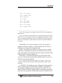
To initiate a self-test:
<▲▼>
From the MAIN MENU scroll to the SELF-TEST
function.
<Enter>
Activate the SELF-TEST function by pressing <Enter>.
This brings up the SELF-TEST initialization screen.
________________________________________________
BeginSelf-Test?
ENTER=Yes ESCAPE=NO
Teledyne Analytical Instruments
45
Operation
________________________________________________
<Enter or Escape> Start the diagnostic testing routine by pressing
<Enter> or cancel out by pressing <Escape>.
If you pressed <Enter> the self-test routine will begin and
after a few moments the results will appear onscreen. The
module is functioning properly if it is followed by OK
otherwise it is followed by BAD. In this case, please
contact TAI Customer Service for an explanation of the
problem.
To return the analyzer to the MAIN MENU, press
<Enter> after the results screen.
If you pressed <Escape> you will be returned to the
Analyze Mode.
4.4.10 Span
The SPAN function is used to calibrate the analyzer.
The analyzer is calibrated using span gas as described in Section 4.1.
This section assumes that this gas has been properly connected and the
line checked for leaks.
To initiate a pan calibration:
<▲▼>
From the MAIN MENU, scroll down to the SPAN
function.
<Enter>
Press <Enter> to activate the SPAN function.
________________________________________________
-> THC Span?
YES
SMP Span?
NO
THC Sp: 8.00 ppm
SMP Sp: 0.00 ppm
Span Begin
________________________________________________
Teledyne Analytical Instruments
46
Operation
The first line determines whether a span calculation will be performed
for THC. The second line determines whether a span calculation will be
preformed for SMP. The third line allows the user to modify the span
target value for THC calibration. The fourth line allows the user to
modify the span target value for SMP.
The last line commences the span (after the following query:
________________________________________________
Begin Span:
ENTER-YES ESCAPE-NO
________________________________________________
Pressing <Enter> enters the SPAN mode in the SMP phase first.
The first pass in the SMP phase only purges the sample gas from the
column (no span calculation is performed this time around). Then the
THC is span calibrated followed by the second pass of the SMP mode,
where the span calculation is performed. The 4030 goes through all of
these phases, but span values are only adjusted if the user selected YES
in the initial menu for the respective phase.
4.4.11 The Alarms Function
The Model 4030 is equipped with two alarms and a system failure
alarm relay. Each alarm relay has a set of form "C" contacts rated for 3
amperes resistive load at 250 VAC. See Figure in Chapter 3, Installation
and/or the Interconnection Diagram included at the back of this manual
for relay terminal connections. The alarm relay contacts are accessible to
the user from the 50-pin Equipment Interface connector.
The system failure alarm has a fixed configuration described in
Chapter 3 Installation.
The concentration alarms can be configured from the ALARM
function screen as follows:
________________________________________________
-> AL-1 DEFEATED
AL-1 HIGH
AL-1 NON-FAILSAFE
AL-1 NON-LATCHING
Teledyne Analytical Instruments
47
Operation
AL-1
AL-1
AL-2
AL-2
AL-2
AL-2
AL-2
AL-2
20.00 ppb
SOURCE THC
ACTIVE
LOW
FAILSAFE
LATCHING
50.00 ppb
SOURCE SMP
________________________________________________
Note: For the purpose of example, Alarm 2 has been set differently
than Alarm 1.
Note: An alarm in 'alarm condition' is signaling that action must be
taken such as correcting the alarm or the analysis concentration. If an
active (not defeated) alarm has been set to HIGH at 20.0 ppb, and the
analysis concentration is above that level, then the 'alarm condition' is
occurring.
DEFEATED: If an alarm is defeated, its relay is de-energized,
regardless of failsafe condition. A defeated alarm does not react to a
transition over its trip point in either direction.
HIGH: If an alarm is set as HIGH, it will not create a new alarm
condition (see latching) if the analysis concentration is below the trip
point, if the analysis concentration is above the trip point, then an alarm
condition will be created or maintained.
FAILSAFE: A non-defeated alarm that is in FAILSAFE mode
energizes an alarm relay in a non-alarm condition and de-energizes an
alarm relay in an alarm condition.
Note: Failsafe condition of an alarm is in software. This is not
related to relays that have both normally-open and normally-closed
terminals.
LATCHING: The latching property configures the alarm such that
the user must manually relieve the alarm condition even though the
concentration no longer violates the trip point of the alarm. So, if an
alarm is NON-LATCHING, and the analysis concentration temporarily
drifts above the trip point of a HIGH alarm, the alarm condition occurs
Teledyne Analytical Instruments
48
Operation
only during the time the concentration is above the trip point. If that
alarm were LATCHING, the alarm condition would persist (even though
the concentration is no longer above the trip point), until the user
released it.
RELEASING A LATCHED ALARM: When alarm conditions are
present, the main analysis screen will have one of the following
messages: 'AL1-', 'AL-2', 'AL12'. Pressing ESCAPE (in the
main/analysis screen) will release a latched alarm and defeat the alarm
until the pertinent phase is re-completed.
TRIGGER POINT: This is the threshold at which an active alarm
can enter into alarm condition. If an alarm is HIGH, ACTIVE, and set
at 20.00 ppb, then when the analysis concentration is at or above 20.00
ppb an alarm condition is initiated or maintained.
SOURCE: The alarm can react to measurement levels of THC,
SMP, or AVG (the average of the previous 2).
CAUTION:
IT IS NOT GOOD PRACTICE TO SILENCE AN
EXISTING ALARM BY SETTING THE ALARM
ATTRIBUTE TO ‘DEFEAT”. THE ALARM WILL NOT
AUTOMATICALLY RETURN TO “ACTIVE” STATUS.
IT MUST BE RESET BY THE OPERATOR BY
PRESSING THE ESCAPE BUTTON. IF IT IS NOT
RESET, YOUR PROCESS WILL BE RUNNING
WITHOUT SAFEGUARDS THIS INSTRUMENT IS
DESIGNED TO PROVIDE.
4.4.12 The Range Function
________________________________________________
-> Range Select: Man
Autorange Src:
THC
Man Rng:
R1
R1: 0-10.0 ppm
R2: 0-100.0 ppm
R3: 0-1000.0 ppm
________________________________________________
Teledyne Analytical Instruments
49
Operation
The value of the upper limit of the currently selected range (AUTO
or MANUAL) affects the voltage and current of the analog outputs on
the rear of the analyzer as well as contact closures indicating which
range is current. The Analog outputs on the rear of the analyzer
represent the proportion of the analysis concentration to the currently
selected range limit.
MANUAL/AUTO RANGE SELECT: In Manual Range select, the
Range indicated on the second line 'Man Rng:' is maintained as the
current range of operation. In Auto Range select, the software
determines the smallest range whose limit is larger than the analysis
concentration.
AUTO RANGE SOURCE: The automatic selection of range can be
set to select according to the THC, SMP, or AVG concentration.
RANGE LIMITS: Ranges may be set as low as 2.0 ppb and as high
as 9999.99 ppm. Range 3 can only be set at a value greater than Range
2. Range 2 can only be set at a value greater than Range 1.
4.4.13 Changing Stream
CHANGE STREAM is not available for standard configurations
of the 4030.
Affects the relay on the rear panel that controls which gas is allowed
to flow to the column and detector.
When the instrument has electronically controlled calibration valves,
the gas stream can be switched here. You can set the incoming gas
source to span, sample (or zero gas, which is nothing more than a 3rd
source of gas) without entering the calibration mode in order to check
instrument response. During a span calibration, the span stream is
activated. After a span calibration, the stream reverts to whatever was
set before the span. This value is not remembered if the power in cycled
on the unit, the analyzer will default to the analyze stream.
Teledyne Analytical Instruments
50
Operation
4.4.14 Analog output Adjustment
The software in this instrument provides a way to enter to manage
the analog output of the analyzer FOR ANALOG CHANNEL 1
ONLY. To access the offset function:
<▲▼>
From the MAIN MENU, scroll to the ANALOG
ADJUST function using the UP/DOWN keys.
<Enter>
Pressing <Enter> activates the function and takes you to
the next screen.
ANALOG-OUT ADJUST
----------------------CH1 Offset:
0
CH1 Gain:
0
CH1 Select:
THC
CH2 Select:
R-ID
-----------------------
<Enter>
<▲▼>
<Enter>
<Escape>
Use the <Enter> key to move over to the Offset field.
Use the UP/DOWN keys to change each digits value.
Use the <Enter> key to save the value.
Use the <Escape> key to revert to the original value.
Use the same procedure to set the gain of the instrument. After the
last digit is entered, the final <Enter> press will accept the gain value.
The values entered do not have explicit units of current or voltage.
Adjustment should be gauged using a voltmeter or current meter
attached to the analog output. When the ANALOG ADJUST menu is
entered the following is displayed:
________________________________________________
-> CH1 mA Offset: 0
CH1 mA Gain: 0
________________________________________________
When the arrow is on the Offset, or when the user presses <Enter> to
modify the offset, the analog output is 4mA plus a value that is
proportionate to the number indicated to the right of 'Offset:' That
number may be modified –500 to 500.
When the arrow is on the Gain, or when the user presses <Enter> to
modify the gain, the output is 20mA scaled by the value to the right of
Teledyne Analytical Instruments
51
Operation
'Gain: ' plus the Offset value plus a value that is proportionate to the
number indicated to the right of 'GAIN:'.
If these 2 values are modified and entered and accepted, then the
analog output will be affected in like manner in ANALYSIS MODE.
That is, it will be scaled by the gain value, then summed with the offset
value.
The analog output for each channel may be set to source THC, SMP,
AVG, WAVE, or R-ID. In the case of THC/SMP/AVG, the output will
reflect the percent of range for the respective selection. In the case of
WAVE, the output will track the FID output. In the case of R-ID, the
output will reflect the selected range: LOW: 1/5 of full scale, MID: 1/2
of full scale, HIGH: 4/5 of full scale.
4.4.15 Standby
This function allows you to place the instrument in STANDBY.
CAUTION:
STANDY SHUTS DOWN POWER TO THE DISPLAYS
ONLY. INTERNAL CIRCUITS ARE STILL ENERGIZED
AND ELECTRICAL SHOCK HAZARD STILL EXISTS.
To place the instrument in STANDBY status:
<▲▼>
From the MAIN MENU, scroll to the STANDBY
function using the UP/DOWN keys.
<Enter>
Pressing <Enter> places the instrument in STANDBY.
To exit STANDBY, scroll again to the STANDBY
function and press <Enter> again.
4.5 Advanced User Functions
The Model 4030 provides additional functions for tailoring the
instrument to your specific application. These functions include:
20. Timing
4.5.1 Timing
Timing controls the parameters of the valve and data acquisition. It
is specific to the setup of the instrument and must be determined at the
factory or TAI trained personnel.
Teledyne Analytical Instruments
52
Appendix
Recommended Spare Parts List
Qty.
P/N
Description
1
1
1
1
1
1
1
1
1
1
1
1
1
1
1
1
1
B74671
B74677
B30927
C75825A
A46128
B-13207
C62371A
B74674A
C65507A
B74677A
L79
F77
L156
L154
A33748
V825
CP2408
PC board, Flame guard & anode power supply
PC board, Electrometer-amplifier
PC board, Temperature control
Micro-processor PC board
Coaxial cable
Sensor Assy.
Display PCB Assy.
Interface to Motherboard PCB Assy.
Backpanel/Power Supply PCB Assy.
Electrometer PCB Assy.
Lamp, neon
Fuse, 6.25A (3 AG)
Lens, red
LED, red
Thermistor assembly
Ten-way valve
PID temperature controller
A minimum charge of US $20.00 is applicable to spare parts orders.
IMPORTANT: Orders for replacement parts should include the part number
and the model and serial number of the system for which the parts are
intended.
Teledyne Analytical Instruments
53
Appendix
Send orders to:
TELEDYNE INSTRUMENTS
Analytical Instruments
16830 Chestnut Street
City of Industry, CA 91749-1580
Telephone: (626) 934-1500
Fax: (626) 961-2538
Web: www.teledyne-ai.com
or your local representative.
Email: [email protected]
Drawing List
D77214
D77215
Model 4030 Outline diagram
Wiring diagram (Rev. 2)
Teledyne Analytical Instruments
54